
Unsticking Presses Jammed on Bottom Dead Center - … · high–speed machine by its manufacturer....
18
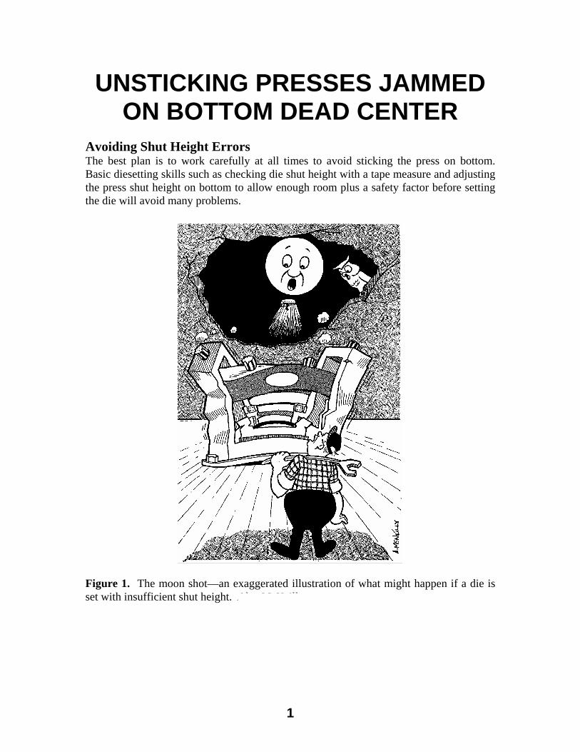
UNSTICKING PRESSES JAMMED ON BOTTOM DEAD CENTER Avoiding Shut Height Errors The best plan is to work carefully at all times to avoid sticking the press on bottom. Basic diesetting skills such as checking die shut height with a tape measure and adjusting the press shut height on bottom to allow enough room plus a safety factor before setting the die will avoid many problems. Figure 1. The moon shot—an exaggerated illustration of what might happen if a die is set with insufficient shut height. Alex McNeilly 1
Transcript of Unsticking Presses Jammed on Bottom Dead Center - … · high–speed machine by its manufacturer....
Unsticking Presses Jammed on Bottom Dead Center - D13.doc - Rev June 13, 2004 David Alkire Smith, 530 Hollywood Drive, Monroe, Michigan 48162-2943 © 1988 -2004
UNSTICKING PRESSES JAMMED ON BOTTOM DEAD CENTER
Avoiding Shut Height Errors The best plan is to work carefully at all times to avoid sticking the press on bottom. Basic diesetting skills such as checking die shut height with a tape measure and adjusting the press shut height on bottom to allow enough room plus a safety factor before setting the die will avoid many problems.
Figure 1. The moon shot—an exaggerated illustration of what might happen if a die is set with insufficient shut height. Alex McNeilly
1

Unsticking Presses Jammed on Bottom Dead Center - D13.doc - Rev June 13, 2004 David Alkire Smith, 530 Hollywood Drive, Monroe, Michigan 48162-2943 © 1988 -2004
Following Basic Good Diesetting Practices
Basic diesetting skills apply to all diesetting situations. It doesn't matter if the assignment is to set a die weighing less than 50 pounds (23 kg) in an OBI press, or to exchange dies weighing many tons (tonnes) each in a multi-slide transfer press. Checking for mechanical interference with a simple tape measure is often required to avoid difficulty.
Making Shut Height This is the most basic task that the diesetter must do. Simply stated, the closed height of the die must not be greater than the shut height (at bottom dead center) of the press. Never guess; instead carefully double-check with a tape measure. However, a mechanical press can become stuck on bottom dead center for a number of reasons. Not all are the fault of the diesetter. Avoiding the problem and solving it should it occur is essential to maintaining production schedules and minimizing maintenance costs. The procedure to make shut-height is:
1. Measure and note the die shut (closed) height 2. Inch the press on bottom dead center 3. Measure the opening—make sure that there is enough room plus a safety factor
The tape measure is as important to a good diesetter as a wrench. Figure 1 is obviously an exaggeration of what might happen if a die is set with insufficient shut height. Should a mechanical press become stuck on bottom dead center, press and tooling damage can occur. In addition, neither the die nor press can be used until the press is unstuck. Setting Exact Shut Height The exact shut height setting is not always critical, especially in blanking operations. However, where critical part dimension features vary with shut height and/or press speed, some trial and error adjustment may be required. For most flat blank through operations setting the shut height so the setup blocks do not quite touch the upper die shoe is usually sufficient. For jobs that require work at bottom dead center such as coining and embossing operations, lead checks are often made to determine the exact shut height. This is a standard procedure when setting many progressive dies. Here, we must allow for press deflection under load. For accurate adjustment, this can only be done with stock being fed into the die under actual production conditions. Press speed will cause shut height to vary. Metals are forming rate sensitive and tend to act harder at higher speeds. In addition, press dynamic factors, especially the reciprocating motion of the slide and elasticity of the pitman(s) will cause slight shut height changes. This factor can be quite critical in high-speed presswork.
2
Unsticking Presses Jammed on Bottom Dead Center - D13.doc - Rev June 13, 2004 David Alkire Smith, 530 Hollywood Drive, Monroe, Michigan 48162-2943 © 1988 -2004
High Speed Press Operation The slide mass and linkage stretch become major factors to consider when setting the shut height of high-speed presses. The definition of high-speed operation is somewhat arbitrary. Some factors that define high-speed operation include:
1. Kinetic forces are significant and cannot be ignored in system analysis 2. Press vibration levels may increase rather than decrease between strokes 3. Tonnage monitor waveform signature data consists of vibration signals 4. Actual shut height changes sufficiently with press speed to require compensation
There is no absolute definition of high-speed pressworking in strokes per minute (SPM). A small precision press operating at speeds in excess of 200 SPM may be defined as a high–speed machine by its manufacturer. However, many inertial factors outlined above are observed in large transfer presses of 2,500 tons (22,240 kN) force capacity at 20 SPM. Since vibration levels can increase to destructive levels in high-speed pressworking, sources of die impact should be minimized. Setup blocks hitting the upper die shoe can increase shock and vibration levels. Many small high-speed presses are set to correct shut height up so a shim will just slide between the set up block and top die shoe at bottom dead center. A typical shim thickness is 0.010 inch (0.254 mm). At press speeds of 1,000 to 1,200 SPM, the shut height may decrease 0.004 inch (0.1.02 mm). However, the setup blocks still do not contact the upper shoe.
Action Plan if the Press Sticks on Bottom Shut height errors frequently result in the press becoming stuck on bottom. It is important to immediately notify press and die maintenance. A well-planned approach to get the press unstuck and inspected for damage is required. Getting the press unstuck and inspecting the press and die for damage should proceed carefully. Both the press maintenance, as well as the tool and die department should be involved. If you immediacy cut off the setup blocks and heating the tie rods should not be a standard procedure. Tie-rod heating will result in loose tie-rods and poor press alignment unless all tie-rods are retensioned. Cutting of setup blocks can result in very costly die damage. There are a number of facts to determine such as the exact crankshaft distance from BDC. Often the press can be reversed and the clutch torque capacity increased within safe limits to get the press unstuck. Simple procedures will usually unstick the press.
3

Unsticking Presses Jammed on Bottom Dead Center - D13.doc - Rev June 13, 2004 David Alkire Smith, 530 Hollywood Drive, Monroe, Michigan 48162-2943 © 1988 -2004
Increasing Press Torque capacity It is always essential to follow both the press and clutch manufacturer’s recommendations concerning maximum torque capacity. Most clutches are actuated by compressed air. Some clutches are actuated by hydraulic pressure. Some large presses have eddy current drives such as the Eaton Dynamatic ®, which are actuated by electromagnetic coils contained within the flywheel assembly.
It is possible to increase the torque capacity to unstick a press. If the press has stalled before bottom dead center, the motor must be reversed. If this is not done, the increase in torque transmission will make the problem worse. Note that full revolution clutches are not designed to transmit torque in the reverse direction. Use Extreme Caution As previously stated, both the press and clutch manufacturer’s recommendations must be followed if the torque capacity of the clutch is increased to unstick a press. Serious equipment damage and endangerment of personnel can occur if excessive torque is developed. For example, if the normal recommended clutch air pressure is 65 psi, increasing the pressure to 85 psi may be permissible. In no case should high nitrogen pressure be applied in an attempt to unstick a press. Use Tonnage Monitor Output Tonnage monitors usually do not give readout of instant or static load. However, many brands have a switch inside the electrical enclosure that disables the automatic rezeroing circuit to permit manual direct current balancing as part of the monitor service procedure. Move this switch to the setup or track mode and connect a sensitive voltmeter to the output provided for a chart recorder. Nearly every monitor has a test point for this purpose although an external output is not provided. Consult the manufacturer for information on where to connect the voltmeter. As the clutch is momentarily engaged, no movement of the ram may appear to occur. However, if the voltage changes slightly in a direction that indicates less machine frame strain, continued clutch engagement or bumping will unstick the press. Working out a procedure for taking this reading in advance of a stuck press problem is strongly advised. Engaging the Clutch of a Stuck Press When forcing the clutch at higher than normal torque capacity, extreme caution is necessary. A way to transmit a high torque for a short period is to engage the clutch at less than full flywheel speed. Repeated engagement at full flywheel speed may fail to unstick the press. Additional Procedures If the press cannot be inched off bottom, additional procedures can be used. In every case, it is essential to minimize the potential for additional damage to the press and tooling. Here, careful methodical teamwork is required.
4

Unsticking Presses Jammed on Bottom Dead Center - D13.doc - Rev June 13, 2004 David Alkire Smith, 530 Hollywood Drive, Monroe, Michigan 48162-2943 © 1988 -2004
Dealing with Stuck C-Frame Presses Loosening the die, gibbing, and using a jack between the ram and bolster at the rear of the opening nearest the C-shaped throat opening usually will unstick the press. Other measures include:
1. Shrinking the die shut height by packing it in dry ice 2. Packing dry ice around the rear of the frame 3. Applying moderate heat to the throat opening—here great care must be exercised
since the opening is already under excessive strain
4. Cutting off the die setup blocks after careful examination of the die 5. Cutting out the die parallels
There is nothing to be gained by cutting off the setup blocks if they are not touching the upper die shoe. This can occur if multiple parts are jammed in the die. Unsticking Straightside Presses Tie-rod straightside presses are generally more straightforward to unstick than C-Frame presses. If forcing the clutch does not succeed, loosening the die and gibbing may free up the press. Shrinking the die with dry ice can prove effective. However, the most straightforward way to unstick the press is by removing the tie-rod tension. This can be achieved by the application of heat, or relieving the preload with hydraulic or mechanical tie-rod tensioning devices. A few straight presses are of economical construction in that they have one-piece frames or plate uprights keyed to the bed and crown. Applying moderate gradual heat to the uprights and packing the die in dry ice may free up a stuck machine of this type. Otherwise, the procedure of cutting parallels and stop blocks is the same as for C-Frame presses. It is especially important to specify hydraulic overload protection for such presses.
Press Tie-Rod Pre-Stressing Theory and Procedures Sucessful pressworking requires that every aspect of the process remain in control. The press and die(s) function as a dependable production system only if machine maintenance, process design, stamping material, and human factors work in harmony. Tie-rods are a frequently overlooked press part. Properly tensioned tie-rods are essential to good pressworking—much the same, as safe driving requires properly inflated tires.
5

Unsticking Presses Jammed on Bottom Dead Center - D13.doc - Rev June 13, 2004 David Alkire Smith, 530 Hollywood Drive, Monroe, Michigan 48162-2943 © 1988 -2004
The structure of almost every top-driven straightside press is held in compression by tie-rods. Normally, four tie-rods are used. The amount of compressive preload used to hold the bed, columns and crown together is determined by the amount of pre-stress or shrink applied to the tie-rods when the press is assembled. Pre-stressed tie-rods are also used to hold some bed made in sections and other large sectionalized press members together in conjunction with keyway locators. This type of construction is uncommon. However, it is a useful way to design very large machines that can be easily shipped in sections. Follow Manufacturer’s Pre-Stressing Procedures Most press service manuals explain the recommended procedure to correctly pre-stress tie-rods. The pre-stressing force is sufficient to maintain a compressive preload on the press housing components at full press capacity plus a safety factor. Once the safety factor is exceeded, the tie-rods stretch, allowing the press crown to lift off the top of the columns. Crown lifting typically occurs at 200% of rated press capacity. Once the crown lifts due to an overload, the tie-rods stretch easily. This serves much like a safety valve to protect the other press parts. The amount of force developed by the machine in case of a catastrophic overload is limited to the yield strength of the tie-rods. The tie-rods, if not damaged to prevent reuse, will require pre-stressing.
Examples of Tie-Rod Pre-Stressing Procedures The tie-rod nuts are installed and manually snugged up. Except for very small machines, it is not feasible to develop enough torque to manually pre-stress the tie-rods sufficiently. Unless the press is equipped with hydraulic tie-rod nuts, or jackbolt actuated tensioning devices, the tie-rods must be heated to achieve correct pretensioning. Once the tie-rod is expanded by heating, the nuts must be tightened a predetermined amount. The correct preloading tension is attained upon cooling. A Generally Accepted Amount to Pre-Stress Tie-Rods Proper pre-stressing of the press tie-rods is essential if a straightside press is to function properly. It is very important to tighten all tie-rods equally and the correct amount. An accepted amount of tie-rod pre-stress that has been used for many years is 0.0007 inches per inch (0.018 mm per 25.4 mm). This equates to approximately 0.0084 inches per foot (0.213 mm per 302.8 MM).
6
Unsticking Presses Jammed on Bottom Dead Center - D13.doc - Rev June 13, 2004 David Alkire Smith, 530 Hollywood Drive, Monroe, Michigan 48162-2943 © 1988 -2004
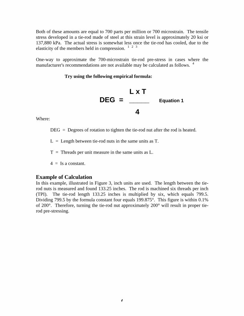
Both of these amounts are equal to 700 parts per million or 700 microstrain. The tensile stress developed in a tie-rod made of steel at this strain level is approximately 20 ksi or 137,880 kPa. The actual stress is somewhat less once the tie-rod has cooled, due to the elasticity of the members held in compression. 1 2 3 One-way to approximate the 700-microstrain tie-rod pre-stress in cases where the manufacturer's recommendations are not available may be calculated as follows. 4
Try using the following empirical formula:
L x T DEG = _____ Equation 1
4 Where: DEG = Degrees of rotation to tighten the tie-rod nut after the rod is heated. L = Length between tie-rod nuts in the same units as T. T = Threads per unit measure in the same units as L. 4 = Is a constant.
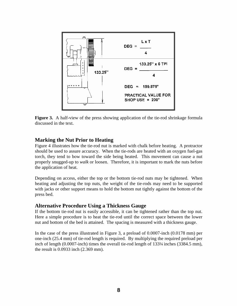
Example of Calculation In this example, illustrated in Figure 3, inch units are used. The length between the tie-rod nuts is measured and found 133.25 inches. The rod is machined six threads per inch (TPI). The tie-rod length 133.25 inches is multiplied by six, which equals 799.5. Dividing 799.5 by the formula constant four equals 199.875°. This figure is within 0.1% of 200°. Therefore, turning the tie-rod nut approximately 200° will result in proper tie-rod pre-stressing.
1 J. Fredline, “Practical Solutions for Troubleshooting Metal Stamping Presses” SME Technical Paper
MS88-200, The Society of Manufacturing Engineers, Dearborn, Michigan, ©1988. 2 “Bliss Power Press Handbook”, E. W. Bliss Company, Hastings, Michigan ©1950. 3 H. Daniels, “Mechanical Press Handbook”, Third Edition, Cahners Publishing Company, Boston, © 1969. 4 Deriving the pre-stress formula basted on threads per unit measure gives a coefficient of 3.968, which is rounded up to four. There are sources of uncertainty greater than this difference. One is the actual Modulus of Elasticity Vs an assumed 30.000 ksi (206,790 mPa) for steel. Another is the uncertain manner in which strain is distributed within the tie rod nut.
7
Unsticking Presses Jammed on Bottom Dead Center - D13.doc - Rev June 13, 2004 David Alkire Smith, 530 Hollywood Drive, Monroe, Michigan 48162-2943 © 1988 -2004
Figure 3. A half-view of the press showing application of the tie-rod shrinkage formula discussed in the text. Smith & Associates Marking the Nut Prior to Heating Figure 4 illustrates how the tie-rod nut is marked with chalk before heating. A protractor should be used to assure accuracy. When the tie-rods are heated with an oxygen fuel-gas torch, they tend to bow toward the side being heated. This movement can cause a nut properly snugged-up to walk or loosen. Therefore, it is important to mark the nuts before the application of heat. Depending on access, either the top or the bottom tie-rod nuts may be tightened. When heating and adjusting the top nuts, the weight of the tie-rods may need to be supported with jacks or other support means to hold the bottom nut tightly against the bottom of the press bed. Alternative Procedure Using a Thickness Gauge If the bottom tie-rod nut is easily accessible, it can be tightened rather than the top nut. Here a simple procedure is to heat the tie-rod until the correct space between the lower nut and bottom of the bed is attained. The spacing is measured with a thickness gauge. In the case of the press illustrated in Figure 3, a preload of 0.0007-inch (0.0178 mm) per one-inch (25.4 mm) of tie-rod length is required. By multiplying the required preload per inch of length (0.0007-inch) times the overall tie-rod length of 133¼ inches (3384.5 mm), the result is 0.0933 inch (2.369 mm).
8

Unsticking Presses Jammed on Bottom Dead Center - D13.doc - Rev June 13, 2004 David Alkire Smith, 530 Hollywood Drive, Monroe, Michigan 48162-2943 © 1988 -2004
Figure 4. Procedure for marking the tie-rod nut with chalk and illustration of how it is turned after heating. In this example, the tie-rod nut is turned 200°. Smith & Associates The four tie-rods are snugged-up as tightly as possible. All tie-rods are heated gradually and the lower tie-rod nuts again tightened up snugly once a 0.0933-inch thick feeler gauge can be snugly inserted into the space resulting from tie-rod expansion. Proper Application of Torch Heat Presses designed for tie-rod pre-stressing with a torch have one or more access holes in the uprights or columns through which the flame is applied to the tie-rod. Before heating, it is very important to thoroughly clean any oil, grease, and debris out of the column housing and press area. Portable fire extinguishers should be available at the job site. A fireguard should be assigned to watch the basement or press pit for any problems during, and for a sufficient period after, the heating work is completed. It is essential to assure all sources of ignition of flammable materials are cool. When applying heat to the tie-rods, mineral fiber insulation is placed between the tie-rods and sides of the column in order to keep the uprights as cool as possible. This will decrease the amount of heat needed to expand the tie-rods and avoid damage to oil lines and wiring. In the event that wiring is too close to the area to be heated, it should be temporarily disconnected and pulled out of the way. Both serious accidents and expensive damage has resulted from control wiring ruined by careless tie-rod heating. All four tie-rods are heated gradually, moving the flame from one to the others in turn. Time is required for the concentrated heat to be conducted along a substantial length of
9
Unsticking Presses Jammed on Bottom Dead Center - D13.doc - Rev June 13, 2004 David Alkire Smith, 530 Hollywood Drive, Monroe, Michigan 48162-2943 © 1988 -2004
the rod. More than one torch may be required for large work. It is important not to overheat the metal. If a small area of the tie rod is heated excessively, the metal may yield as the rod shrinks, resulting in less than the desired amount of pre-stressing. The final nut adjustments should be completed at the same time to insure an even preload on the frame of the machine. Finally, the press is allowed to cool and the machine alignment checked following standard testing procedures. Electrical Resistance Tie-Rod Heaters Many presses built over the last several decades have holes drilled several feet (a meter or more) into the top end of the tie-rods. This hole is intended for the insertion of electrical heating elements designed especially for pre-stressing tie-rods. The larger sizes are designed for connection to a three phase current source. A matched set of four heaters is used simultaneously. This assures uniform heating. Once the proper expansion is attained, the tie-rod nuts are tightened. The use of electrical heaters is much easier and the results more certain than flame heating. However, a plan should be worked out in advance, especially if an emergency such as a press stuck on bottom should occur. The heaters draw a large amount of current, so a safe electrical supply of the required capacity, voltage, and phase must be available. Other common sense precautions include making sure that no liquids or debris is in the holes before inserting the heaters. The heater must be fully inserted into the hole. If the heater surface projects above the tie-rod, it will overheat and may ruin the unit.
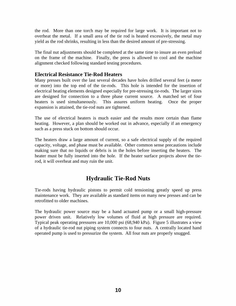
Hydraulic Tie-Rod Nuts Tie-rods having hydraulic pistons to permit cold tensioning greatly speed up press maintenance work. They are available as standard items on many new presses and can be retrofitted to older machines. The hydraulic power source may be a hand actuated pump or a small high-pressure power driven unit. Relatively low volumes of fluid at high pressure are required. Typical peak operating pressures are 10,000 psi (68,940 kPa). Figure 5 illustrates a view of a hydraulic tie-rod nut piping system connects to four nuts. A centrally located hand operated pump is used to pressurize the system. All four nuts are properly snugged.
10

Unsticking Presses Jammed on Bottom Dead Center - D13.doc - Rev June 13, 2004 David Alkire Smith, 530 Hollywood Drive, Monroe, Michigan 48162-2943 © 1988 -2004
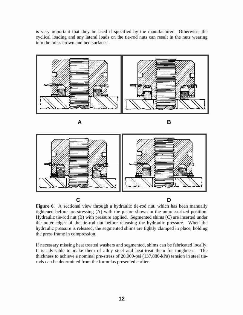
Figure 5. Top of a press crown illustrating hydraulic tie-rod piping and hand actuated pump. Verson Corporation Even with such high operating pressures, the effective piston area must be several times larger than the cross sectional area of the tie-rod. The hydraulic force must be capable of tensioning the tie-rod to well over 20,000 psi (138,880 kPa), the normal working load of the tie-rod. Additional force is required to install the nut and to assist in getting a press stuck on bottom of stroke freed-up in an emergency . Hydraulic Nut Tensioning Sequence Figure 6A-D illustrates sectional views through a hydraulic tie-rod nut. The nut on the tie-rod threads had been tightened manually in order to remove all clearance between the top and bottom nuts and the mating surfaces on the press bed and crown. The piston is shown in Figure 6A in the withdrawn or unpressurized position. Figure 6B illustrates a hydraulic tie-rod nut with the pressure applied. Here the piston is shown in the fully extended position. The piston is a donut shaped ring fitted with hydraulic packing. The matching piston bore is machined into the tie-rod nut body. Note the pressure inlet connection and air bleed valve. Once the nut is pressurized, segmented steel shims are inserted around the outer edge of the nut. Figure 6C illustrates the shims inserted before releasing the hydraulic pressure. The thicknesses of the shims, which are supplied by the press manufacturer, provide the correct value of tie-rod pre-tensioning for the press.
Finally, the hydraulic pressure is released as illustrated in Figure 6D. Here, the segmented shims are tightly clamped in place. The press frame is uniformly held in compression. If the shims are missing or damaged, replacement shims should be ordered from the press builder. Some presses have large heat-treated washers used under the tie-rod nuts to spread the load over the crown and bed surface. They also serve to avoid wear to these surfaces. It
11
Unsticking Presses Jammed on Bottom Dead Center - D13.doc - Rev June 13, 2004 David Alkire Smith, 530 Hollywood Drive, Monroe, Michigan 48162-2943 © 1988 -2004
is very important that they be used if specified by the manufacturer. Otherwise, the cyclical loading and any lateral loads on the tie-rod nuts can result in the nuts wearing into the press crown and bed surfaces.
A B
C D Figure 6. A sectional view through a hydraulic tie-rod nut, which has been manually tightened before pre-stressing (A) with the piston shown in the unpressurized position. Hydraulic tie-rod nut (B) with pressure applied. Segmented shims (C) are inserted under the outer edges of the tie-rod nut before releasing the hydraulic pressure. When the hydraulic pressure is released, the segmented shims are tightly clamped in place, holding the press frame in compression. Verson Corporation If necessary missing heat treated washers and segmented, shims can be fabricated locally. It is advisable to make them of alloy steel and heat-treat them for toughness. The thickness to achieve a nominal pre-stress of 20,000-psi (137,880-kPa) tension in steel tie-rods can be determined from the formulas presented earlier.
12

Unsticking Presses Jammed on Bottom Dead Center - D13.doc - Rev June 13, 2004 David Alkire Smith, 530 Hollywood Drive, Monroe, Michigan 48162-2943 © 1988 -2004
Jackbolt Actuated Tie-Rod Nuts Figure 7 illustrates a unique patented way to tensioning press tie-rod nuts. The concept was developed by SUPERBOLT® Inc. of Carnegie, Pennsylvania. One of the most widespread applications for this product is in large hydraulic presses used in the forging industry. Other uses include large steam turbine housing nuts and reciprocating compressor crosshead piston rod retaining nuts. As illustrated in Figure 7, a SUPERBOLT® is used with a special engineered washer supplied by the manufacturer. The standard mechanical tensioner (MT) series are available for thread diameters from 0.75 through 6 inches although designs up to 40 inches (1016 mm) have been provided. Metric sizes are also stocked with large sizes available in special designs and large sizes.
Figure 7. SUPERBOLT® used with a special engineered washer supplied by the manufacturer. The standard mechanical tensioner is available off the shelf through 6 inches and metric sizes through M160. SUPERBOLT® Inc.
13

Unsticking Presses Jammed on Bottom Dead Center - D13.doc - Rev June 13, 2004 David Alkire Smith, 530 Hollywood Drive, Monroe, Michigan 48162-2943 © 1988 -2004
Advantages of Jackbolt Actuated Mechanical Tensioners Figure 8 illustrates a worker torquing a SUPERBOLT® thrust collar assembly to tension an 18-inch (457.2 mm) tie-rod to a preload of 2,625,000 pounds (11,676 kN). The jackbolt torque being applied with a torque wrench is 275 foot pounds (372.9 NM) The standard MT series is designed to pre-stress bolted connections to forces in excess of 70,000 psi (482,589 kPa). Since this is 3.5 times the nominal 20,000 psi (137,880 kPa) preload used for press tie-rods, the SUPERBOLT® should be capable of relieving extreme press overloads simply by backing off the special jackbolts. The highest jackbolt torque required for the large standard sizes to obtain a pre-stress load of 70,000 psi is 390 foot pounds (528.84 NM). This stress may be more than the yield strength of many press tie-rods. Again, the nominal tie-rod tension is approximately 20,000 psi (137,880 kPa).
Torquing a Forging Press SUPERBOLT®
Figure 8. A worker torquing a SUPERBOLT® thrust collar assembly to tension an 18-inch (457.2-mm) tie-rod to a preload of 2,625,000 pounds (11,676 kN). The jackbolt torque being applied with a torque wrench is 275 foot pounds (372.9 NM) SUPERBOLT® Inc.
14

Unsticking Presses Jammed on Bottom Dead Center - D13.doc - Rev June 13, 2004 David Alkire Smith, 530 Hollywood Drive, Monroe, Michigan 48162-2943 © 1988 -2004
It is possible to manually back off the jackbolts of a press stuck on bottom with a heavy-duty wrench and high strength socket. However, some modification of the standard instillation procedure may be required. The standard procedure is hand tighten the nuts without the screws projecting before torquing the jackbolts. Backing off the jackbolts can relieve an overload of approximately two times press capacity. Some presses can develop three to four times their rated tonnage in case of an extreme overload. A possible solution is to screw the jackbolts so they project a slight amount before torquing to the specified value. The nut manufacturer should be consulted before altering the normal procedure. Jackbolt Thread Torque Accuracy Requirements The SUPERBOLT® is a simple concept. By reducing the percentage of torque applied to the jackbolts, the tie-rod preload is reduced in direct proportion. In order to assure accurate pre-stress values, it is important to make sure that the threads are clean and that the manufacturer’s recommended lubricant for the application is used. The SUPERBOLT® is an acceptable alternative for prudent consideration as a replacement for conventional tie-rod nuts. Of course, for a specific application, the press manufacturer’s recommendations should be followed together with the users engineering staff’s advice. It is always wise to remember that press modifications of any kind may result in an unexpected outcome and consequential liability for bad results. In no event should these devices be used to increase tie-rod preload beyond the press manufacturer’s recommendations. The devices are only to be considered a potentially convenient means of obtaining correct tie-rod preload which may be more accurate and less costly than alternative methods discussed previously.
Assembling Straightside Presses Having Tie-Rods With few exceptions, the frames of most straightside presses are held in compression by four tie-rods. The process of assembling the press is termed stacking the machine. Stacking the Press The bed, uprights, and crown may first be stacked together. The tie-rods may be inserted last if there is sufficient overhead clearance. An eyebolt hole is usually provided for lifting. Otherwise, a cable sling must be used.
15

Unsticking Presses Jammed on Bottom Dead Center - D13.doc - Rev June 13, 2004 David Alkire Smith, 530 Hollywood Drive, Monroe, Michigan 48162-2943 © 1988 -2004
An alternative procedure is to insert the tie-rods before stacking the crown and in some cases the uprights. Some very large machines require a cylindrical pit or well under each tie-rod location after placing and leveling the bed in position, the tie-rods are lowered through the bed into the wells. Once the uprights and crown are stacked in place, the tie-rods are lifted into position with an eyebolt and cable. Correcting Machine Damage If a lack of flatness is found, the machine may have been subjected to an extreme overload condition. If such an overload resulted in a large lateral force, mating surfaces on the bed, uprights and crown may be warped. The only good solution is to re-machine or replace all machine components as needed. If proper performance is expected, all fits and tolerances must be restored to the manufacturer's specifications. Benefits of Proper Tie-Rod Pre-Stressing Maintaining correct tie-rod tension is one of many press maintenance tasks that cannot be overlooked if quality pressworking is to be accomplished at minimum cost. This is just one part of a proactive maintenance program good stampers follow. Avoiding press damage and maintaining alignment is a key to lower die maintenance costs and better part quality. This will help any stamper be a low cost producer with a reputation for quality and dependable delivery.
Action to Take in the Event of a Large Overload Common causes of large overloads are diesetting errors and foreign object damage. Should such an overload occur, the machine might have damage that may make it dangerous to operate. The press should be removed from service and thoroughly inspected for damage. After a conventional inspection with dial indicators and inside micrometers, load cell testing in conjunction with waveform signature analysis is an especially good procedure. Load cell tests provide an accurate means to gradually increase the force of the machine to full capacity. This test permits observation for cracked press parts. Look for breathing of cracked or loose components and irregular operation. The waveform signature can be used to detect loose (stretched) tie-rods as well as quickly pinpoint timing errors caused by partially sheared keys, twisted shafting, failed shear collars and similar problems. In the event that no damage is apparent after performing the tests described earlier in this chapter, a note of the incident should be made in the press maintenance records. Although no damage may be detected, latent damage such as stress crack initiation may have occurred which could cause a failure later. In case of future irregular operation, the machine should be removed from service and thoroughly inspected, as is always the proper procedure.
16

Unsticking Presses Jammed on Bottom Dead Center - D13.doc - Rev June 13, 2004 David Alkire Smith, 530 Hollywood Drive, Monroe, Michigan 48162-2943 © 1988 -2004
A B Figure 9. The characteristic appearance of a failed crankshaft due to gradual crack propagation (A) shows most of the fracture has oyster shell marks typical of crack growth bands. The appearance of a failed crankshaft due to a catastrophic overload: the entire fracture surface displays the rough torn metal typical of a tensile failure. Smith & Associates Slow Crack Propagation Figure 9A shows the characteristic appearance of a failed crankshaft due to gradual crack propagation. The crack may have been initiated by a sudden overload. The crack growth leading to failure may have occurred over several years of operation. The failure itself often occurs quite unexpectedly under moderate loads. Most of the fracture surface at displays "oyster shell" marks typical of stop and go crack growth under varying load conditions. This crack growth pattern is caused by slight changes in the direction of crack propagation. These occur with changes in load levels. The final tensile failure occurs when there is no longer enough area of sound metal to transmit the required torque. That area has a rough appearance indicating that the metal was torn apart. The final part of the fracture is essentially a tensile failure of the remaining sound metal. Often, there is also considerable evidence of discoloration and fretting corrosion, especially in the old part of the fracture. Here the opposite sides of the crack have been rubbing together under conditions of high pressure for some time. Gradual failures can have many contributing causes. While a sudden long-forgotten overload may have initiated the crack, there may be other causes. Repeated cycling at loads too high for the machine design may initiate the crack. The ultimate fracture often occurs unexpectedly under moderate loads.
17

Unsticking Presses Jammed on Bottom Dead Center - D13.doc - Rev June 13, 2004 David Alkire Smith, 530 Hollywood Drive, Monroe, Michigan 48162-2943 © 1988 -2004
Sharp corners will create a stress riser. A generous corner radius should be provided in the design of crankshafts and other press parts. Small cracks may be difficult to spot. If the machine is disassembled for any reason, it is wise to carefully inspect the crankshaft, gears, pitmans and other highly stressed components with an appropriate non-destructive testing method. Die penetrant or magnetic particle inspections are both good methods for finding small cracks in machine components. Sudden Catastrophic Failure The majority of press component failures exhibit the evidence of crack propagation illustrated in Figure 9A. However, a very large overload of typically three or more times press capacity, may result in a complete fracture of a component. Figure 9B illustrates a crankshaft failure resulting from a single extreme overload. A typical cause is an extreme lack of shut height when diesetting, or mechanical interference due to hitting multiple blanks in a drawing or reforming operation. If such a failure occurs, it is very likely that several other machine components may have been damaged as well. Careful inspection and alignment of the entire machine is required. Inspect Driving Keys for Tightness All driving keys should be checked for tightness and signs of any play. Even a slight amount of play can permit the key to work loose resulting in increasingly severe movement and wear. If not corrected, the key may fall out or experience shear failure due to repeated shock or overloading. Tensile stress concentration at the corners of the keyway may result in crack propagation and component failure. This is often a contributing cause when gear hubs fail. Treat the Press and Die as a Single Unit At one time there used to be silly differences of opinion between the Press Maintenance Department and the Tool and Die Department in many plants. The finger pointing usually revolved around stamping process problems—especially stuck presses. Today, we can no longer afford the luxury of delaying the resolution of a stamping process problem. We have all of the traditional press diagnostic tools involving static measurements. In addition, we have advanced technology to apply on the shop floor. To compete, we must maximize the team approach to problem solving.
NOTES: ____________________________________________________ _____________________________________________________________ _____________________________________________________________
18


