Unsteady forces and flows in low Reynolds number hovering...
12
449 The demonstrated importance of unsteady effects in insect flight has prompted recent development of better experimental and computational tools to investigate unsteady forces and vortical flows around a flapping wing. In particular, dynamically scaled robots of both the hawkmoth (Ellington et al., 1996) and fruitfly (Dickinson et al., 1999) have been The Journal of Experimental Biology 207, 449-460 Published by The Company of Biologists 2004 doi:10.1242/jeb.00739 We compare computational, experimental and quasi- steady forces in a generic hovering wing undergoing sinusoidal motion along a horizontal stroke plane. In particular, we investigate unsteady effects and compare two-dimensional (2D) computations and three- dimensional (3D) experiments in several qualitatively different kinematic patterns. In all cases, the computed drag compares well with the experiments. The computed lift agrees in the cases in which the sinusoidal changes in angle of attack are symmetrical or advanced with respect to stroke positions, but lags behind the measured 3D lift in the delayed case. In the range of amplitudes studied here, 3–5 chords, the force coefficients have a weak dependence on stroke amplitude. As expected, the forces are sensitive to the phase between stroke angle and angle of attack, a result that can be explained by the orientation of the wing at reversal. This dependence on amplitude and phase suggests a simple maneuver strategy that could be used by a flapping wing device. In all cases the unsteady forces quickly reach an almost periodic state with continuous flapping. The fluid forces are dominated by the pressure contribution. The force component directly proportional to the linear acceleration is smaller by a factor proportional to the ratio of wing thickness and stroke amplitude; its net contribution is zero in hovering. The ratio of wing inertia and fluid force is proportional to the product of the ratio of wing and fluid density and the ratio of wing thickness and stroke amplitude; it is negligible in the robotic wing experiment, but need not be in insect flight. To identify unsteady effects associated with wing acceleration, and coupling between rotation and translation, as well as wake capture, we examine the difference between the unsteady forces and the estimates based on translational velocities, and compare them against the estimate of the coupling between rotation and translation, which have simple analytic forms for sinusoidal motions. The agreement and disagreement between the computed forces and experiments offer further insight into when the 3D effects are important. A main difference between a 3D revolving wing and a 2D translating wing is the absence of vortex shedding by a revolving wing over a distance much longer than the typical stroke length of insects. No doubt such a difference in shedding dynamics is responsible in part for the differences in steady state force coefficients measured in 2D and 3D. On the other hand, it is unclear whether such differences would have a significant effect on transient force coefficients before the onset of shedding. While the 2D steady state force coefficients underpredict 3D forces, the transient 2D forces measured prior to shedding are much closer to the 3D forces. In the cases studied here, the chord is moving between 3 to 5 chords, typical of hovering insect stroke length, and the flow does not appear to separate during each stroke in the cases of advanced and symmetrical rotation. In these cases, the wing reverses before the leading edge vortex would have time to separate even in 2D. This suggests that the time scale for flow separation in these strokes is dictated by the flapping frequency, which is dimensionally independent. In such cases, the 2D unsteady forces turn out to be good approximations of 3D experiments. Key words: insect flight, computational fluid dynamics, biofluid dynamics, vorticity field, two-dimensional force, three-dimensional force. Summary Introduction Unsteady forces and flows in low Reynolds number hovering flight: two-dimensional computations vs robotic wing experiments Z. Jane Wang 1, *, James M. Birch 2 and Michael H. Dickinson 3 1 Theoretical and Applied Mechanics, Cornell University, Ithaca, NY 14853, USA, 2 Integrative Biology, University of California, Berkeley, CA 94720, USA and 3 Bioengineering, California Institute of Technology, Pasadena, CA 91125, USA *Author for correspondence (e-mail: [email protected]) Accepted 3 October 2003
Transcript of Unsteady forces and flows in low Reynolds number hovering...

449
The demonstrated importance of unsteady effects in insectflight has prompted recent development of better experimentaland computational tools to investigate unsteady forces and
vortical flows around a flapping wing. In particular,dynamically scaled robots of both the hawkmoth (Ellington etal., 1996) and fruitfly (Dickinson et al., 1999) have been
The Journal of Experimental Biology 207, 449-460Published by The Company of Biologists 2004doi:10.1242/jeb.00739
We compare computational, experimental and quasi-steady forces in a generic hovering wing undergoingsinusoidal motion along a horizontal stroke plane.In particular, we investigate unsteady effects andcompare two-dimensional (2D) computations and three-dimensional (3D) experiments in several qualitativelydifferent kinematic patterns. In all cases, the computeddrag compares well with the experiments. The computedlift agrees in the cases in which the sinusoidal changes inangle of attack are symmetrical or advanced with respectto stroke positions, but lags behind the measured 3D lift inthe delayed case.
In the range of amplitudes studied here, 3–5 chords, theforce coefficients have a weak dependence on strokeamplitude. As expected, the forces are sensitive to thephase between stroke angle and angle of attack, a resultthat can be explained by the orientation of the wing atreversal. This dependence on amplitude and phasesuggests a simple maneuver strategy that could be used bya flapping wing device.
In all cases the unsteady forces quickly reach an almostperiodic state with continuous flapping. The fluid forcesare dominated by the pressure contribution. The forcecomponent directly proportional to the linear accelerationis smaller by a factor proportional to the ratio of wingthickness and stroke amplitude; its net contribution iszero in hovering. The ratio of wing inertia and fluid forceis proportional to the product of the ratio of wing andfluid density and the ratio of wing thickness and strokeamplitude; it is negligible in the robotic wing experiment,but need not be in insect flight.
To identify unsteady effects associated with wingacceleration, and coupling between rotation andtranslation, as well as wake capture, we examine the
difference between the unsteady forces and the estimatesbased on translational velocities, and compare themagainst the estimate of the coupling between rotationand translation, which have simple analytic forms forsinusoidal motions. The agreement and disagreementbetween the computed forces and experiments offerfurther insight into when the 3D effects are important.
A main difference between a 3D revolving wing and a2D translating wing is the absence of vortex shedding by arevolving wing over a distance much longer than thetypical stroke length of insects. No doubt such a differencein shedding dynamics is responsible in part for thedifferences in steady stateforce coefficients measured in2D and 3D. On the other hand, it is unclear whether suchdifferences would have a significant effect on transientforce coefficients before the onset of shedding. While the2D steady state force coefficients underpredict 3D forces,the transient 2D forces measured prior to shedding aremuch closer to the 3D forces. In the cases studied here, thechord is moving between 3 to 5 chords, typical of hoveringinsect stroke length, and the flow does not appear toseparate during each stroke in the cases of advanced andsymmetrical rotation. In these cases, the wing reversesbefore the leading edge vortex would have time to separateeven in 2D. This suggests that the time scale for flowseparation in these strokes is dictated by the flappingfrequency, which is dimensionally independent. In suchcases, the 2D unsteady forces turn out to be goodapproximations of 3D experiments.
Key words: insect flight, computational fluid dynamics, biofluiddynamics, vorticity field, two-dimensional force, three-dimensionalforce.
Summary
Introduction
Unsteady forces and flows in low Reynolds number hovering flight:two-dimensional computations vsrobotic wing experiments
Z. Jane Wang1,*, James M. Birch2 and Michael H. Dickinson31Theoretical and Applied Mechanics, Cornell University, Ithaca, NY 14853, USA, 2Integrative Biology,
University of California, Berkeley, CA 94720, USAand 3Bioengineering, California Institute of Technology,Pasadena, CA 91125, USA
*Author for correspondence (e-mail: [email protected])
Accepted 3 October 2003

450
developed to perform controlled measurements of flows andforces. In parallel, researchers have developed directnumerical simulations to probe the detailed vortex dynamicsand unsteady forces in flapping flight (Liu et al., 1998; Wang,2000a,b; Sun and Tang, 2002; Ramamurti and Sandberg,2002).
Given the complexity of modeling fluid flows in threedimensions (Liu et al., 1998; Sun and Tang, 2002; Ramamurtiand Sandberg, 2002), it would be desirable to determine ifsimpler models provide results that are consistent with thosegenerated in experiments. Here, we compare two-dimensional(2D) computations of hovering flight against robotic wingexperiments. 2D computations are appealing partly becauseof their relative simplicity and efficiency. Obviously, 2Dcomputations cannot predict three-dimensional (3D) effects;on the other hand, it is almost impossible to attach thesignificance of 3D effects without knowing what happens in2D flow. Therefore, in addition to being relevant to caseswhere the flow is approximately 2D, as with large wing aspectratio, when compared with 3D experiments or computations,2D computations can offer useful insight into the relativesignificance of 3D effects, as we will discuss at the end of thepaper.
Comparing computations and experiments is delicate, partlybecause it is almost impossible to match any two setupsexactly, and partly because it is tempting to present results thatcompare well, thereby biasing the interpretations. Therefore, itis essential to test the methods in qualitatively different flowsgenerated by different wing kinematics.
In addition to comparing the experimental andcomputational forces, we also evaluate the relativeimportance of unsteady effects. These include wingacceleration, both in translation and rotation, and interactionsbetween the wing the existing flow. Most recent work usinga robotic fruit fly focused on kinematics based on tetheredflight measurements. These kinematics have relativelyconstant translational velocity in the mid-stroke and largeaccelerations and sharp rotations at the end of strokes. Inthese strokes, pronounced peaks appear near the end of eachstroke. These peaks were attributed to either wing rotationand wake capture (Dickinson et al., 1999; Birch andDickinson, 2003), or rotational and translational acceleration(Sun and Tang, 2002; Sane and Dickinson, 2002). Thesinusoidally varying strokes studied here offer a set ofkinematics where the relative contribution of some of thedynamic effects can be theoretically estimated. For example,we estimate the relative contribution that wing rotation andacceleration make to the quasi-steady forces. We alsoestimate the wing inertia relative to the fluid force, as well asthe non-inertial forces due to wing acceleration relative tothe pressure forces associated with vorticity flux. Given thatthe free flight kinematics of fruit flies appear to be moresinusoidal than those derived from tethered flight (Fry etal., 2003), our results, though using an idealized kinematics,may nevertheless relate to the forces generated by the realflies.
Materials and methodsExperimental method
We obtained both force and flow data using a dynamicallyscaled robotic fly, as described in prior studies (Dickinson andGötz, 1993; Dickinson et al., 1999; Birch and Dickinson,2003). At the base of one arm was attached a 2D force sensorthat measured forces parallel and perpendicular to the wingsurface. The force sensor at the wing base was designed to beinsensitive to the force moments; thus the force distribution onthe wing did not influence overall force magnitude. Lift anddrag forces were then calculated from the perpendicular shearforces measured by the sensor. The wing consisted of a2.25·mm thick piece of Plexiglas, cut to the planform ofa Drosophila wing. When attached to the force sensor, totalwing length was 0.25·m. The wing and arm apparatuswere lowered into a 1·m×1·m×2·m Plexiglas tank filled with1.8·m3 of mineral oil (density 0.88×10³·kg·m–3; kinematicviscosity=115·cSt). By changing flapping frequency we couldoperate the robot at Reynolds numbers Re between 50 and 200.The design of the robotic arms permitted the wing to movewith three degrees of freedom (measured as stroke amplitude,stroke deviation from horizontal, and wing rotation) and acustom program written in Matlab (Mathworks v.5.3) allowedus to program arbitrary kinematic patterns. To simplify thecomparisons with the 2D computational fluid dynamics model,we created a simple back-and-forth wing beat pattern with nostroke plane deviation.
We used digital particle image velocimetry (DPIV) tomeasure the flow structure in a 841·cm2 area centered on thewing. The oil was seeded with air forced through a ceramicwater filter stone, creating a dense bubble field. After thelarger bubbles rose to the surface, the remaining bubbles,although slightly positively buoyant, were effectivelystationary for the duration of each exposure pair. Acommercial software package controlling a dual Nd-YAGlaser system (Insight v.3.2, TSI Inc., St Paul, MN, USA)created two identically positioned light sheets approximately2.5·mm thick separated by 2000·µs. These light sheets wereparallel to the wing chord and positioned at 0.65R, where R isthe wing span, and timed to fire when the wing chord wasdirectly in front of the high-speed video camera placedperpendicular to the laser sheet. We chose 0.65R as our pointof measurement because in a prior DPIV study in which thewake was viewed from the rear, 0.65R was the position inwhich the circulation was the greatest (Birch and Dickinson,2003). We captured one image per stroke from a 29·cm×29·cmarea centered on the wing during each of the four strokes.After saving the captured images, the trigger for the laser wasadvanced and the starting position of the wing was adjustedto line up with the camera at the appropriate time beforestarting the next trial (Birch and Dickinson, 2003). Werepeated this procedure until we had divided each stroke into10 equally spaced intervals. In this way, we quantified thefluid flow from the perspective of the wing through fourdownstroke/upstroke cycles, although this paper will only
Z. J. Wang, J. M. Birch and M. H. Dickinson

451Computation vs experiment in insect flight
report on the wake dynamics during the fourth stroke. Foreach image-pair captured, a 2-frame cross-correlation of pixelintensity peaks with 50% overlap of 64·pixel×64·pixelinterrogation areas resulted in 900·velocity·vectors/image.Vector validation resulted in the removal of only 2 of 9000vector values; these were filled by interpolation of a meanvalue from a 3 × 3 nearest neighbor matrix. A custom programwritten in Matlab (v.5.0) calculated vorticity, ω=∇× u, fromvelocity fields smoothed using using a least-squares finitedifference scheme.
Computational method
The computation models a thin wing element of ellipticcross section under the same kinematics as performed in theexperiments. The computation of flows around this hoveringwing employs a fourth-order finite difference scheme ofNavier–Stokes equation in vorticity-stream functionformulation (E and Liu, 1996). The scheme is implemented inthe elliptic coordinates with appropriate boundary conditionsto account for the wing motion (Wang, 2000a,b). See alsoRussell and Wang (2003) for an alternative method employingCartitian grids appropriate for multiple wings.
The two-dimensional Navier-Stokes equation governing thevorticity in the elliptic coordinates has the following form:
where u is the velocity field, ω the vorticity field, v is thekinematic viscosity and S is the local scaling factor, S(µ,θ)=cosh2µ–cos2θ resulting from coordinates transformation. Thederivatives are with respect to the elliptic coordinates (µ,θ),whose mesh points are naturally clustered around the tips andthe body of the ellipse to resolve the boundary layer. It isconvenient to express both the vorticity and velocity in termsof the stream function, Ψ: u=–∇×Ψ and ω=∇ 2Ψ. Theconformal transformation results in a constant coefficientPoisson equation for the stream function Ψ, which can besolved via Fast Fourier Transform (FFT) efficiently.
The Navier–Stokes equation is solved in a frame fixed tothe wing. In the 2D vorticity stream function formulation, thenon-inertial frame introduces only one extra term, therotational acceleration of the wing. Other non-inertial termscan be expressed as a gradient of a potential function. Thusthey can be absorbed into the pressure term. The curl of thegradient of pressure is zero. The body motion is reflected inthe far field boundary conditions, and the no-slip boundarycondition at the wing is enforced explicitly through thevorticity and stream function boundary conditions. Morespecifically, on the wing, we set Ψ=c, where c is a constant,to satisfy the no-penetration boundary condition, and ∂Ψ/∂n=0to satisfy the no-slip boundary condition. At far field, we set∇×Ψ =–(U0+r×Ω0), where U0 and Ω0 are the translational androtational velocity of the wing, respectively, r is the position
relative to the wing center, and ω=0. The exact boundarycondition on Ψ can be recovered by solving the Poissonequation twice (Wang, 1999). For this computation, the farfield boundary condition is correct to the dipole order.
A fourth-order Runge–Kutta scheme is used for the timeiterations, which exhibits a stability domain for thisexplicit scheme. The stability condition includes twoCourant–Friedrich–Levy (CFL)-like conditions related to theconvection and diffusion time scales over a mesh size:
dt1 = C1ds2sinh2µ0/4v·, (3)
dt2 = C2dssinhµ0·, (4)
where ds=min(dµ, dθ), µ=µ0 at the ellipse, and C1=C2=0.8.The time step is chosen to be min(dt1, dt2). The basic timeiteration in each computation step involves the followingsequence: ωn→Ψn+1→un+1→ωn+1, where superscripts indicatethe time-step. To resolve the flow, 10 grid points are typicallyneeded along the radial direction in the boundary layer, and atleast 30 points in the azimuthal direction around each tip,whose length scale is estimated by its radius of curvature.The resolution for Re~100 is 128×256 for the followingcomputations. The radius of the computational boundary istypically 10 times the chord length.
The forces on the ellipse can be computed from integratingthe stress tensor along the body. Writing the Navier–Stokesequation in the coordinates fixed to the wing, we have:
= ·u = 0·, (6)
u|wing = 0·, (7)
where U0 and Ω are the translational and rotational velocity ofthe wing, and p the pressure. The last three terms correspondsto the non-inertial force due to rotational acceleration, theCoriolis force, and the centrifugal force. The Coriolis force andthe centrifugal force disappear in the 2D vorticity equationbecause they can be recast in terms of the gradient of apotential function.
The velocity and vorticity are solved in the non-inertialcoordinates, which are then transformed into the inertial frame.The forces are calculated in the inertial frame by integratingthe viscous stress:
where Fp and Fv denote pressure and viscous forces. ρ is thefluid density, Aw the total area of the wing, s is the tangent
(9)ωsds ,Fv = ρv⌠⌡
(8)∂ω∂r
dU0
dt(y, –x)ds+ ρAwFp = ρv ,
⌠⌡
(5)
∂u
∂t=pρ+ (u ·=)u = – + v∆u – dU0/dt
–dΩdt
×r + 2Ω×u + Ω×(Ω×r ) ,
(2)Su) = 0 ,!= · (
(1)∂(Sω)
∂tSu ·=)ω = v=2ω ,!+ (

452
vector along the ellipse, and the integral is over the surface ofthe ellipse. The second term in Fp is similar to the buoyancyforce associated with hydrostatic pressure, i.e. fluids acceleratewith –(dU0/dt).
Wing motion, choice of parameters and normalization
The wing follows a sinusoidal flapping and pitching motion.Specifically, the wing sweeps in the horizontal plane andpitches about its spanwise axis with a single frequency f:
α(t) = α0 + βsin(2πft + φ)·, (11)
where x(t) is the position of the center of the wing, and α(t) isthe wing orientation with respect to the x-axis. By definition,the translational and angular velocities are given byU0(t)=dx(t)/dt and Ω(t)=dα(t)/dt. The parameters include thestroke amplitude A0, the initial angle of attack α0, theamplitude of pitching angle of attack β, the frequency f and thephase difference φ between x(t) and α(t). In the experiments,such a motion is confined to an arc about the wing root, andin the 2D computations, the motion is along a straight line.
The translational motion of the wing is completely specifiedby two dimensionless parameters, the Reynolds number,Re=Umaxc/ν=πfA0c/ν, and A0/c, where Umax is the maximumwing velocity, and c the chord. In the subsequent studies, wefix f but vary A0/c and study its effect on the flow. For clarity,we will report the value of A0/c directly instead of Re. A0/cvaries from 2.8 to 4.8, with resulting Re from 75 to 115,appropriate for fruitflies. Other parameters α0, β and f are fixedto be π/2, π/4 and 0.25·Hz, respectively.
A main variable of interest in this study is the phase delaybetween rotation and translation, φ, which was shown to be asensitive parameter in force generation (Dickinson et al., 1999;Wang, 2000b). Three cases, φ=π/4, 0 and –π/4, correspondingto the advanced, symmetrical and delayed rotation (Dickinsonet al., 1999), will be studied for each A0/c.
We normalize the computational and experimental forces bythe maxima of their corresponding quasi-steady forces, asdescribed in the next section. Our choice for the normalizationis dimensionally the same as the conventional choice, Gρu2
rmsc,but has the advantage of normalizing away features specific tothe wing, such as its thickness and geometry. This is becausethat force dependence of the wing geometry is sometimesrelatively simple. For example, the force coefficients ofellipses of different thickness were shown to have almost thesame functional dependence on the angle of attack but differentmagnitude (see fig.·6 in Wang, 2000a). The experimental forcecoefficients of the robotic fly wing also show little dependenceon the wing planform. If the dependence on the geometry inthe steady and unsteady forces is similar, then their ratio doesnot depend sensitively on the geometry of the wing. Thiswould allow us to compare wings of different cross sectionsand planforms. Although comparing the force coefficientsappears to be a natural thing to do, one must be cautious when
comparing 2D and 3D force coefficients. The lift coefficientof 1 has different meanings in experiments and computations,unless the sectional lift coefficient in a 3D wing is a constant.Strictly speaking, the numbers should only be compared withinthe computations or the experiments.
Quasi-steady forces
Before discussing the unsteady forces, we first describe thecalculation of the quasi-steady forces based on both thetranslational and rotational velocity. Because the wing operatesat a large range of angles of attack, from 0° to 135°, theKutta–Joukowski lift, which works for attached flowassociated with small angles of attack, is clearly inapplicable.Instead, we determine the quasi-steady coefficientsempirically, using both the robofly experiments andcomputation of a steady translating wing at a fixed angle ofattack. The lift and drag coefficients, defined with respect tothe far field flow, are measured at a time when the forces reacha temporary plateau after the initial transients (see for example,fig.·2 in Dickinson et al., 1999; fig.·5 in Wang, 2000a). Forcesat all angles are measured at a fixed time, t=2 in dimensionlesstime scale.
From the 3D experiments, the lift and drag coefficients arewell approximated by:
CL = 0.225 + 1.58sin(2.13α – 7.2°)·, (12)
CD = 1.92 + 1.55cos(2.04α – 9.82°)·, (13)
where the angles are expressed in degrees. A similar fit isobtained using our 2D computed data:
CL = 1.2sin(2α)·, (14)
CD = 1.4 – cos(2α)·, (15)
where α is the angle of attack. This fit is shown in Fig.·1.
(10)A0
2cos(2πft) ,x(t) =
Z. J. Wang, J. M. Birch and M. H. Dickinson
Fig.·1. Quasi-steady lift CL (circles) and drag CD (crosses)coefficients measured from computation compared to the empiricalformulae described by Equations·14,15 (solid and broken lines,respectively).
0 20 40 60 80 100 –0.5
0
0.5
1
1.5
2
2.5
For
ce c
oeffi
cien
ts
CD
CL
Angle of attack α (degrees)

453Computation vs experiment in insect flight
The constants depend on the Reynolds number, details ofthe wing, etc. Unlike the Kutta–Joukowski lift, which is validat small values of α and is proportional to sinα,Equations·12,13 and 14,15 are valid for all values of α and
depend explicitly on 2α, rather than α. The 2α dependenceis consistent with the symmetry of a plate. Moreover, it isconsistent with the theoretical prediction of lift and drag of astalled wing:
CL = πsin(2α)/(4 + πsinα)·, (16)
CD = πsin2(α)/(4 + πsinα)·, (17)
which is derived assuming complete flow separation in thewake (von Karman and Burgers, 1963). The theoryunderpredicts the magnitude of the forces, but gives roughlythe right shape of the force curve. In addition, Equations·16,17make it apparent that the net force in the stalled case is normalto the wing, a prediction confirmed by our computations andexperiments (Figs·2–4). We refer to the forces, Gρu2CL and
Fig.·2. Computational and experimental lift and drag coefficientsduring advanced rotation (φ=π/4; A0/c=2.8). (A) Lift (CL) and drag(CD) during the first four complete strokes. Red, experimentalmeasurements; blue, computations. The time is normalized with theflapping period. The force is normalized by the maxima of thecorresponding quasi-steady forces. (B) Experimental and (C)computational force vectors superimposed on wing positions, plottedat equal time intervals. The green line represents the wing chord;filled circles, the leading edge; arrows indicate force vectors on thewing. R, right; L, left.
0 0.5 1 1.5 2 2.5 3 3.5 4
0 0.5 1 1.5 2 2.5 3 3.5 4
–1 –0.5
00.5
11.5
2
CL
–1.5 –1
–0.50
0.51
1.52
Time
CD
A
Stroke L
Stroke R
B
Stroke L
Stroke R
C
Fig.·3. Computational and experimental lift and drag coefficientsduring symmetrical rotation (φ=0; A0/c=2.8). Details as in Fig.·2.
0 0.5 1 1.5 2 2.5 3 3.5 4
0 0.5 1 1.5 2 2.5 3 3.5 4
–1–0.5
00.5
11.5
2
CL
–1.5 –1
–0.50
0.51
1.52
Time
CD
A
Stroke L
Stroke R
B
Stroke L
Stroke R
C

454
Gρu2CD, as the quasi-steady translational lift (LT) and drag(DT), respectively.
In the case of a translating and rotating wing, theinstantaneous velocity of the wing varies along the chord, asu(x,t)=u0(t)+Ω0(t)×x, where x is the position on the chordmeasured from the pitching axis. In the case of constant smallpitching amplitude and constant translating velocity, thepotential theory (Munk, 1925) predicts the associated lift tobe:
LR = π/2ρc2U0Ω0·. (18)
Note that Equation·18 includes both the pressure lift of atranslating and rotating wing in the absence of circulation(Magnus force) and the lift due to circulation given by theKutta’s condition. There is no a priori reason as to which of
the quasi-steady forms should fit in the unsteady case better,since both use assumptions that are invalid in unsteady cases.Recently, revised quasi-steady models have been proposed tofit these forces (Sane and Dickinson, 2002). For the purpose ofthis paper, we simply compare LR, LT and DT with the unsteadyforces. It turns out that for the prescribed motions here, LR
deviates substantially from the unsteady forces, while LT
approximates the unsteady forces reasonably well. Therefore,in the subsequent discussions, we will use LT as an estimatefor the quasi-steady forces.
ResultsComparison of measured and computed forces
Twelve kinematics are analyzed here: four strokeamplitudes, 60°, 80°, 100° and 120°, at three phase delays,φ=π/4, 0 and –π/4. The range of amplitudes corresponds to theend-to-end amplitude:chord ratios of 2.8, 3.6, 4.2 and 4.8 at70% span. The computational parameters are chosen to matchboth the Reynolds number Re and the amplitude:chord ratio,A0/c. In particular, A0 is estimated to be the projection of thearc length at 70% span onto a 2D plane. The location at 70%span was chosen because the sectional circulation is nearmaximal there (J. M. Birch, W. Dickson and M. H. Dickinson,manuscript submitted for publication) and the interferencefrom the trailing edge vortex is small. Once we fix thecomputational units for time and length, i.e. T=1 and c=2.0, theviscosity is also fixed in computational units.
Figs·2–4 summarize the results for variation in φ. Eachfigure shows the comparison of experimental andcomputational force coefficients over the first four cycles.In addition, instantaneous force vectors are shown insuperposition with the traveling wing during the second stroke.
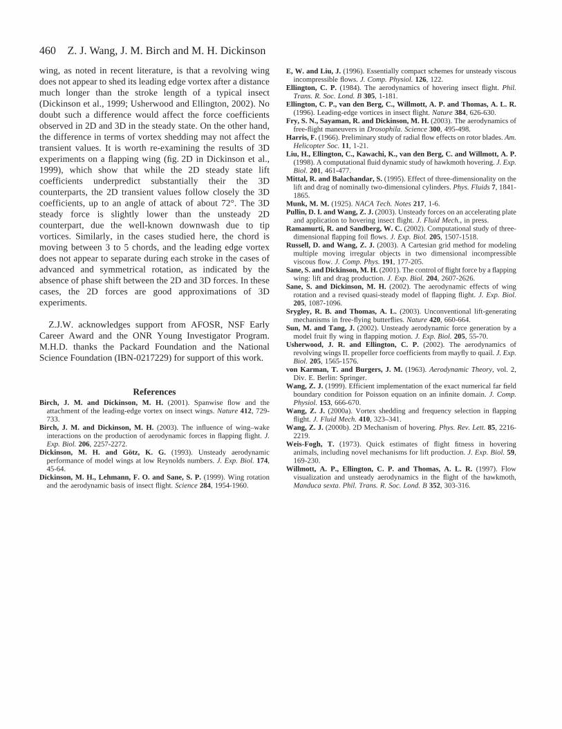
The wing motion in these cases differs in the angle of attackat the end of stroke. The angles of attack are π/4, π/2 and 3π/4,respectively, in the advanced (φ=π/4), symmetrical (φ=π/2)and delayed (φ=–π/4) rotation cases, as shown in the forcevector plots. The delayed rotation case is unusual from thepoint of view of operating an airfoil. After each reversal, thewing has angles of attack greater than π/2, which leads to adownward lift (see Fig.·4). However, insects or bio-mimeticdevices may use such a stroke to reduce the force on one wing,and thus generate a torque to turn. In addition, when the wingis moving at an angle greater than π/2, the flow separatesquickly, which is qualitatively different from the other twocases. Thus it also provides a good case for testingcomputations and experiments in different scenarios.
In all cases, the forces quickly settle into an almost periodicstate after two strokes. The computational drag follows theexperimental drag closely in all three cases. Lift agrees well inthe first two cases (Figs·2, 3), but shows a clear phase delay inthe case of delayed rotation (Fig.·4). Notice that the shift occursonly after the first stroke. The averaged experimental lift anddrag coefficients are (0.93, 1.28), (0.86, 1.34) and (0.38, 1.10),for the advanced, symmetrical and delayed rotation,respectively. The averaged computational lift and drag
Z. J. Wang, J. M. Birch and M. H. Dickinson
Fig.·4. Computational and experimental lift and drag coefficientsduring delayed rotation (φ=–π/4; A0/c=2.8). Details as in Fig.·2.
0 0.5 1 1.5 2 2.5 3 3.5 4
0 0.5 1 1.5 2 2.5 3 3.5 4
–1 –0.5
00.5
11.5
2
CL
–1.5 –1
–0.50
0.51
1.52
Time
CD
A
Stroke L
Stroke R
B
Stroke L
Stroke R
C

455Computation vs experiment in insect flight
coefficients are (1.10, 1.36), (0.82, 1.44) and (0.19, 1.21),respectively, for the corresponding cases. We will return to thepresence and absence of the phase shift in lift in these threedifferent cases when we discuss the 3D effects.
The averaged force coefficients depend weakly on strokeamplitude, as shown in Fig.·5. In the case of φ=π/4, the averageexperimental lift coefficients are 0.93, 0.99, 0.95 and 0.93 atA0/c=2.8, 3.6, 4.2 and 4.8, respectively. The correspondingcomputational lift coefficients are 1.07, 1.0, 0.9 and 0.9. Thedrag coefficients are 1.28, 1.19, 1.12 and 0.93 in experiments,and 1.36, 1.34, 1.24 and 1.16 in computation. This indicatesthat the total force scales roughly with A0
2, as expected. Within
this range of amplitude variation, the flows are qualitativelysimilar for a given choice of φ. Although we only show theφ=π/4 case, the results are similar for φ=–π/4 and φ=0.
The average lift depends sensitively on φ, as emphasizedbefore (Dickinson et al., 1999; Wang, 2000b). For example, inthe case of A0/c=2.8, the averaged values for experimental lift,CL are 0.93, 0.86 and 0.38, for φvalues of 0.25π, 0 and –0.25π,respectively. The comparable quasi-steady lift coefficients are0.75, 0.95 and 0.75. This dependence on φ can be understoodintuitively, based on two facts. First, the deviation between theunsteady forces and quasi-steady forces occurs mostly after theflip of each stroke. Second, the instantaneous forces in all thesecases are typically normal to the wing, as indicated in the forcevector plots in Figs·2–4, and as discussed in Materials andmethods. Therefore, the contribution to lift and drag can becorrelated with the instantaneous orientation of the wing at theend of each stroke: π/4, π/2 and 3π/2, for φ=π/4, φ=0 andφ=–π/4, respectively. One expects an increase in both lift anddrag when φ=π/4, a decrease of lift and increase of drag whenφ=–π/4, and relatively small change in lift, but a large increasein drag for φ=0. These indeed are consistent with both theexperimental and computational forces.
Comparison of experimental and computed vorticity fields
As a further comparison between computation andexperiments, we show side by side the snapshots of thevorticity field near the wing from experimental DPIVmeasurements and computational results (Fig.·6). Ten framesare shown for each period. The colors indicate the strength ofthe vorticity field. In Fig.·6, columns A and C are computedvorticity, and B and D are experimental vorticity in a 2D slice.The simulations appear to capture the major features of vortexdynamics through a complete stroke cycle. Notice that the fluidmomentum is directed downward by pairs of vortices, similarto those shown in asymmetric strokes that model dragonflywing kinematics (Wang, 2002b). In 3D, the pairs of vorticescan be cross-sections of a donut-shaped vortex ring. Thestructure of the downward momentum jet, characterized by theaveraged velocity field over a cycle, is examined elsewhere forboth the symmetric and asymmetric strokes strokes (Z. J.Wang, manuscript submitted for publication). Also notice thateven the kinematics of left and right strokes are identical, butthe flow field differs slightly. This can be seen by comparingcolumns A and C in Fig.·6. The wing positions are mirrorimages, but the flows deviate slightly from the mirrorsymmetry. Such a deviation may be inconsequential in termsof average lift, but worth keeping in mind when interpretingthe precise time course of forces.
Unsteady forces vs quasi-steady forces
The differences between the unsteady and quasi-steadyforces have been analyzed extensively for fruitfly kinematics,based on results from tethered animals, with relatively constanttranslational velocity in the mid-stroke and large accelerationand sharp rotations at the end of strokes. The unsteady effectswere dominant near the wing reversal, where they contribute
2 2.5 3 3.5 4 –1
0
1
2
CL
2 2.5 3 3.5 4
–1
0
1
2
Time
CD
A
2 2.5 3 3.5 4 –1
0
1
2
CL
2 2.5 3 3.5 4
–1
0
1
2
Time
CD
B
Fig.·5. Force traces for different amplitudes. (A) Experimental forcecoefficients for advanced rotation (φ=π/4) and three strokeamplitudes, A0/c=2.8 (red), 3.6 (blue) and 4.2 (green).(B) Computational force coefficients for the same parameters. Thetime is normalized with the flapping period. The force is normalizedby the maxima of the corresponding quasi-steady forces.

456
to the rotational effect and the wake capture (Dickinson et al.,1999). The discrepancy between experimental measures offorces and flows (Birch and Dickinson, 2003) and a CFDmodel of nearly identical conditions (Sun and Tang, 2002)
raises a debate about the physical basis of these unsteadyeffects. Here we do not attempt to resolve these discrepancies,but probe the presence of unsteady effects in a different set ofkinematics. In Fig.·7, we compare the unsteady forces with the
Z. J. Wang, J. M. Birch and M. H. Dickinson
Fig.·6. Vorticity plot in the case of A0/c=4.8, φ=0. Ten frames are shown in the fourth stroke. Red, counterclockwise rotating vortices; blue,clockwise rotating vortices. The wing is in black. (A,C) Computed vorticity; (B,D) digital particle image vorticity data in a 2D slice at 0.65R.See Materials and methods for details. Each pair in A,B and C,D corresponds to the same time during a stroke. The time sequence is indicatedby the numbers on each plate. The color scale for vorticity of computation and experiments do not correspond to the exact same contour values,so the figure should be viewed as a qualitative comparison.
A B C D

457Computation vs experiment in insect flight
0 0.5 1 1.5 2 2.5 3 3.5 4
0 0.5 1 1.5 2 2.5 3 3.5 4
–1 –0.5
00.5
11.5
2
CL
–1.5 –1
–0.50
0.51
1.52
CD
0 0.5 1 1.5 2 2.5 3 3.5 4 –1.5
–1 –0.5
00.5
11.5
2
CD
0 0.5 1 1.5 2 2.5 3 3.5 4 –1.5
–1 –0.5
00.5
11.5
2
CD
A
0 0.5 1 1.5 2 2.5 3 3.5 4 –1
–0.50
0.51
1.52
CL
0 0.5 1 1.5 2 2.5 3 3.5 4 –1
–0.50
0.51
1.52
CL
δδ
r r
u
r r u
u
u
B
δδ
r r u
r r
u
u
u
Time
0 0.5 1 1.5 2 2.5 3 3.5 4
0 0.5 1 1.5 2 2.5 3 3.5 4
–0.5
0
0.5
1
CL
–1.5 –1
–1
–0.5
0
0.5
1
–1
–0.5
0
0.5
1
–1
–0.50
0.51
1.52
CD
0 0.5 1 1.5 2 2.5 3 3.5 4 –1.5
–1 –0.5
00.5
11.5
2
CD
0 0.5 1 1.5 2 2.5 3 3.5 4 –1.5
–1 –0.5
00.5
11.5
2
CD
0 0.5 1 1.5 2 2.5 3 3.5 4
CL
0 0.5 1 1.5 2 2.5 3 3.5 4
CL
Time
C
D
E
F
δδ
r r u
r r
u
u
u
Fig.·7. Force comparison between experiment, computation and quasi-steady predictions for (A,D) advanced (φ=π/4), (B,E) symmetric (φ=0)and (C,F) delayed (φ=–π/4) rotations. (A–C) Force traces of four strokes starting from rest. Red, experimental force; blue, computational force;green, quasi-steady estimates using Equations·14–17. Forces are normalized as in Figs·2–4. (D–F) Difference trace (red) between theexperimental forces and quasi-steady forces. Linear acceleration du(t)/dt (blue), and an estimate of rotational force u(t)Ω(t) (green) are shownin arbitrary scale since we are only interested in their basic time course. Broken vertical lines mark the wing reversal during t=[1,2]. Featuresassociated with rotation (r) and unsteady circulation due to wing acceleration (u), are labelled accordingly.

458
steady state forces based on the translational velocity. In thecase of advanced rotation, the unsteady effects can contributean additional 50% to the total lift, and in the case of delayedrotation, they can reduce the total lift by a factor of 2–3. It isalso clear that the quasi-steady forces based on translationalvelocity alone do not predict the time-dependent forces duringa sinusoidal flapping.
To gauge the relative importance of different unsteadyeffects, we examine the difference between unsteady forcesand estimates based on the translational velocity, as shown inFig.·7D–F. Ideally we wish to decompose, if possible, theunsteady force approximately into a sum of separate terms,which can be related to wing acceleration, the couplingbetween rotation and translation, wing–wake interaction, etc.However, in the absence of quantitative prediction of theseeffects, we can only offer a plausible decomposition bycorrelating the force peaks with the time course of translationaland rotational velocity.
The coupling between translation and rotation can bemodeled by CrotΩ(t)u(t), a form predicted by classical theoryof a translating and pitching motion (Munk, 1925), and testedin robotic fruitfly experiments (Sane and Dickinson, 2002),where Crot is assumed to be a constant that depends on thecenter of rotation. Part of CrotΩ(t)u(t) is the Magnus forcecaused by the pressure difference due to velocity difference,given by Bernoulli’s law, and another part is due to additionalcirculation caused by the rotational motion to satisfy the Kuttacondition (Munk, 1925). In the three kinematic patterns studiedhere, the peaks (labeled ‘r’ in Fig.·7) associated with rotation,are picked by matching (with a small shift) the force curve tothe maximum of Ω(t)u(t). The positions of these measuredforce peaks vary in the three cases, in accordance with the shiftof the peak positions of u(t)Ω(t). The variation occurs at thesame time scale as u(t)Ω(t).
Other unsteady effects occur near the wing reversal(labeled ‘u’ in Fig.·7). The position of these effects occurroughly at the same time in all three kinematics. These forcepeaks do not follow the trace of du(t)/dt, thus do not behaveas the classical added mass. These force peaks are likelyrelated to the unsteady growth of vorticity and wake–wakeinteraction, which do not have simple analytic expressionsin general. Regardless of its physical basis, the mostsubstantial contribution of this unsteady effect is on drag(Fig.·7B,C,E,F).
We also note that the peaks alternate in size from stroke tostroke in the experimental lift, most obvious in Fig.·7A,D. Onepossible explanation is that this asymmetry reflects themechanical artifact due to gear backlash. However a smalldegree of asymmetry is also observed in the computationaldata, e.g. the vorticity field as shown in Fig. 6 and the forcesin Figs·2–4. At Re=0, the left and right strokes, which aremirror images about the vertical axis, would generate forcesthat have the same symmetry; i.e. the lift from left and rightstrokes are identical and the drag forces are of equal size butin the opposite direction. Here, the Reynolds number is finiteand sufficiently large that the force can depend on the history
of flow. One possibility for breaking the symmetry in forces isby the initial condition.
While identification of the above features is useful whendissecting the unsteady force traces, it is also relevant todetermining their net contributions. The force directlyproportional to the linear acceleration can have sharp peaks,but it has a zero contribution in reciprocal motions. Thepressure force of a rotating and translating plate, approximatedby u(t)Ω(t), has a non-zero net contribution in the caseswhere φ≠0, since [sin(2πft)cos(2πft+φ)]~sinφ. The unsteadyvortex force due to wing acceleration has eluded simpleanalytical expressions, except for power-law start up flow,where both the added mass term and the vortex force arecalculated analytically and numerically (Pullin and Wang,2003). The unsteady forces contribute to both lift and drag,both predicted in theory (Pullin and Wang, 2003) and seen herein Fig. 7.
Fluid forces and wing inertia
Among various terms contributing to the fluid forces, thepressure force dominates. The viscous force is smaller byroughly a factor proportional to 1/√Re. The pressure force dueto non-inertial effects resulting from translational androtational acceleration averages to zero in hovering when thepitching axis is centered at the chord. The magnitude of theinstantaneous non-inertial translational force is also small forthese sinusoidal motions. In particular:
where Fω is the pressure force due to vorticity, FB is theeffective buoyancy due to wing acceleration, b is the thicknessof the wing and A0 is the amplitude of the stroke. In thederivation of Equation·19, we have used the fact thatdU0/dt~2πfU0 and U0~2πfA0.
Fig.·8 illustrates the contribution of Fω (broken line) to thetotal force (solid line). In kinematics where there is a fastacceleration at the end of the stroke, the force will have sharppeaks at the end of the stroke, but the net contribution is zero,as discussed before.
Finally, we estimate the inertial force associated withwing acceleration with respect to the fluid force. The inertialforce in the experiment turns out to be negligible comparedto the fluid forces, as shown experimentally (Sane andDickinson, 2001). Here is a simple estimate to explain whythis is so:
where Cf is the force coefficient, of order 1, b is the thicknessof the plate and A0 the amplitude of the stroke. For the roboflywing, (ρwing/ρfluid)~1.3 and (b/A0)!1, hence the wing inertia isnegligible. For a real insect wing, (ρwing/ρfluid)~103, so that eventhough the wing is very thin, its inertia may not be negligible.Weis-Fogh’s early data showed that the ratio is about 30%
(20)Fwing
Ffluid
ρwing
ρfluid
b
A0
Mwingd2U0/dt2
GCfρU02Aw
= ,~
(19)FB
Fω
b
A0
ρAw(dU0/dt)
CfGρU02c
= ,~
Z. J. Wang, J. M. Birch and M. H. Dickinson

459Computation vs experiment in insect flight
(Weis-Fogh, 1973). It will be interesting to check this againstthe biological data. Similar results can be obtained for thepitching torque:
where c is the chord. Again, in the experiments the moment ofwing inertia is also negligible during a sinusoidal motion asstudied here.
Discussion Given that flow around real and model insect wings exhibits
3D effects such as spanwise flow, it is tempting to concludethat 2D computations have little to offer. Here we see that thesuccess and failure of a 2D model in capturing the forces in3D experiments can provide important insights. In both theadvanced and symmetrical rotation cases, the 2D forces arevery similar to the 3D forces. Why do they agree? In addition,what do we learn from comparisons between the 2Dcomputation and the 3D experiments?
First, a notable difference between the experimental andcomputational forces is seen in the delayed rotation, wherethere is a clear phase shift between the computed and measuredlift. In the canonical example of flow past a 2D cylinder and a3D sphere, the forces during von Karman vortex shedding alsoshow a phase shift, which was argued to be a generic featurebetween 2D and 3D flows (Mittal and Balachandar, 1995). Inview of this, the absence of the phase shift in the advanced andsymmetrical cases are particularly interesting. The differencein flow structure in the three cases may be worth furtherinvestigation.
Second, these results are relevant to recent discussions aboutthe role of 3D effects on delayed stall. Insects are known toflap their wings at angles of attack much higher, around 35°(Ellington, 1984), than the stall angle of a conventional airfoil,about 12°. As suggested by Ellington et al. (1996), the pressuregradient from root to tip within the vortex core might drivespanwise flow that stabilizes the leading edge vortex byconvecting away the vorticity. The spanwise flow was indeedseen by smoke visualization in the robotic hawkmothexperiment, where Re≈5000 (Ellington et al., 1996; Willmottet al., 1997). This proposed mechanism is thought to be
analogous to that occurring on delta wing aircraft, in whichspanwise flow through the vortex core maintains the stability.But as discussed previously (Ellington et al., 1996), the exactconditions for establishing spanwise flow in leading-edgevortex for rotary wings are not completely understood. Forexample, a helicopter rotor also experiences a pressuregradient, centrifugal and Coriolis forces, but no large-scalespanwise flow is observed (Harris, 1966). Recent smokevisualization of free-flying butterflies also did not observesubstantial spanwise flow, but reported high variability of 3Dflow patterns (Srygley and Thomas, 2003). DPIV images offlow field in a robotic fruitfly experiment, where Re≈150,showed no substantial spanwise flow inside the core of leadingedge vortex, but instead indicted substantial spanwise flowbehind the leading edge vortex, which connects to the tipvortex (Birch and Dickinson, 2001). Strictly speaking, there isno contradiction among these experiments regarding thespanwise flow. It is likely that the spanwise flow within thevortex core occurs only at sufficiently large Reynolds numberas in the case of hawkmoth, but not at low Reynolds number,as in the case of fruitflies. The details of the spanwise flow canalso depend on the wing shape and kinematics. The highvariability of the 3D flow patterns shown by these differentexperiments, however, makes it difficult to conclude thatspanwise flow is crucial for generating sufficient lift by ahovering insect.
An alternative explanation for why the conventional stalldoes not seem to affect a flapping insect wing relates to thetime scale governing the flow separation that leads to stall. Forexample, a 2D translating wing at an angle of attack of 40°and Re=1000, does not show a drop in time-dependent forceuntil the chord travels for about 4 chords, after which theforces become oscillatory due a von Karman shedding (fig.~6in Wang, 2000a). Therefore, in theory there is no need foradditional mechanisms to stabilize the leading edge vortex ifthe wing travels less than about 4 chords. The early datacompiled by Weis-Fogh (1973) showed that ratios of stroke-arc to wing-chord of different species during hovering,including bats (Plecotus auritus), birds (hummingbirds),butterflies and moths (Lepidoptera), wasp and bees(Hymenoptera) and flies (Diptera), have values less than 4.The beetles (Coleoptera) have values between 5 and 6. A maindifference between a 3D revolving wing and a 2D translating
(21)τwing
τfluid
bc
A02
,~
0 0.2 0.4 0.6 0.8 1 1.2 1.4 1.6 1.8 2 –1
–0.5
0
0.5
1
1.5
2
Time
CD
Fig.·8. Contributions to drag coefficients.Solid line, total drag; broken line,contribution due to vorticity flux alone.The parameters in the wing kinematicsare: A0/c=2.8, φ=π/4.
460
wing, as noted in recent literature, is that a revolving wingdoes not appear to shed its leading edge vortex after a distancemuch longer than the stroke length of a typical insect(Dickinson et al., 1999; Usherwood and Ellington, 2002). Nodoubt such a difference would affect the force coefficientsobserved in 2D and 3D in the steady state. On the other hand,the difference in terms of vortex shedding may not affect thetransient values. It is worth re-examining the results of 3Dexperiments on a flapping wing (fig.·2D in Dickinson et al.,1999), which show that while the 2D steady state liftcoefficients underpredict substantially their the 3Dcounterparts, the 2D transient values follow closely the 3Dcoefficients, up to an angle of attack of about 72°. The 3Dsteady force is slightly lower than the unsteady 2Dcounterpart, due the well-known downwash due to tipvortices. Similarly, in the cases studied here, the chord ismoving between 3 to 5 chords, and the leading edge vortexdoes not appear to separate during each stroke in the cases ofadvanced and symmetrical rotation, as indicated by theabsence of phase shift between the 2D and 3D forces. In thesecases, the 2D forces are good approximations of 3Dexperiments.
Z.J.W. acknowledges support from AFOSR, NSF EarlyCareer Award and the ONR Young Investigator Program.M.H.D. thanks the Packard Foundation and the NationalScience Foundation (IBN-0217229) for support of this work.
ReferencesBirch, J. M. and Dickinson, M. H. (2001). Spanwise flow and the
attachment of the leading-edge vortex on insect wings. Nature412, 729-733.
Birch, J. M. and Dickinson, M. H. (2003). The influence of wing–wakeinteractions on the production of aerodynamic forces in flapping flight. J.Exp. Biol.206, 2257-2272.
Dickinson, M. H. and Götz, K. G. (1993). Unsteady aerodynamicperformance of model wings at low Reynolds numbers. J. Exp. Biol.174,45-64.
Dickinson, M. H., Lehmann, F. O. and Sane, S. P.(1999). Wing rotationand the aerodynamic basis of insect flight. Science284, 1954-1960.
E, W. and Liu, J. (1996). Essentially compact schemes for unsteady viscousincompressible flows. J. Comp. Physiol.126, 122.
Ellington, C. P. (1984). The aerodynamics of hovering insect flight. Phil.Trans. R. Soc. Lond. B305, 1-181.
Ellington, C. P., van den Berg, C., Willmott, A. P. and Thomas, A. L. R.(1996). Leading-edge vortices in insect flight. Nature384, 626-630.
Fry, S. N., Sayaman, R. and Dickinson, M. H.(2003). The aerodynamics offree-flight maneuvers in Drosophila. Science300, 495-498.
Harris, F. (1966). Preliminary study of radial flow effects on rotor blades. Am.Helicopter Soc.11, 1-21.
Liu, H., Ellington, C., Kawachi, K., van den Berg, C. and Willmott, A. P.(1998). A computational fluid dynamic study of hawkmoth hovering. J. Exp.Biol. 201, 461-477.
Mittal, R. and Balachandar, S.(1995). Effect of three-dimensionality on thelift and drag of nominally two-dimensional cylinders. Phys. Fluids 7, 1841-1865.
Munk, M. M. (1925). NACA Tech. Notes 217, 1-6.Pullin, D. I. and Wang, Z. J. (2003). Unsteady forces on an accelerating plate
and application to hovering insect flight. J. Fluid Mech., in press.Ramamurti, R. and Sandberg, W. C.(2002). Computational study of three-
dimensional flapping foil flows. J. Exp. Biol. 205, 1507-1518.Russell, D. and Wang, Z. J. (2003). A Cartesian grid method for modeling
multiple moving irregular objects in two dimensional incompressibleviscous flow. J. Comp. Phys. 191, 177-205.
Sane, S. and Dickinson, M. H.(2001). The control of flight force by a flappingwing: lift and drag production. J. Exp. Biol.204, 2607-2626.
Sane, S. and Dickinson, M. H.(2002). The aerodynamic effects of wingrotation and a revised quasi-steady model of flapping flight. J. Exp. Biol.205, 1087-1096.
Srygley, R. B. and Thomas, A. L.(2003). Unconventional lift-generatingmechanisms in free-flying butterflies. Nature420, 660-664.
Sun, M. and Tang, J.(2002). Unsteady aerodynamic force generation by amodel fruit fly wing in flapping motion. J. Exp. Biol.205, 55-70.
Usherwood, J. R. and Ellington, C. P.(2002). The aerodynamics ofrevolving wings II. propeller force coefficients from mayfly to quail. J. Exp.Biol. 205, 1565-1576.
von Karman, T. and Burgers, J. M. (1963). Aerodynamic Theory, vol. 2,Div. E. Berlin: Springer.
Wang, Z. J. (1999). Efficient implementation of the exact numerical far fieldboundary condition for Poisson equation on an infinite domain. J. Comp.Physiol.153, 666-670.
Wang, Z. J. (2000a). Vortex shedding and frequency selection in flappingflight. J. Fluid Mech.410, 323–341.
Wang, Z. J. (2000b). 2D Mechanism of hovering. Phys. Rev. Lett. 85, 2216-2219.
Weis-Fogh, T. (1973). Quick estimates of flight fitness in hoveringanimals, including novel mechanisms for lift production. J. Exp. Biol.59,169-230.
Willmott, A. P., Ellington, C. P. and Thomas, A. L. R. (1997). Flowvisualization and unsteady aerodynamics in the flight of the hawkmoth,Manduca sexta. Phil. Trans. R. Soc. Lond. B352, 303-316.
Z. J. Wang, J. M. Birch and M. H. Dickinson