![Chipley Banner. (Chipley, Florida) 1897-08-21 [p ].€¦ · 50 GTS FOR 10 CTS A complete novel and type and a illuitratedbook tUlngbow better looking raintent free for 10 ficeTolnmrs](https://static.fdocuments.us/doc/165x107/608a287a1e2e01394f4bd38c/chipley-banner-chipley-florida-1897-08-21-p-50-gts-for-10-cts-a-complete.jpg)
Unofficial Manual of the Chipley Custom Machine T2...
37
The Un official Manual of the Chipley Custom Machine T2 Pump Marker V. 1
Transcript of Unofficial Manual of the Chipley Custom Machine T2...

The Unofficial Manual of the Chipley Custom Machine T2 Pump Marker
V. 1

www.pumpenstein.com I. Table of Contents:
I. T2 Marker Schematic
a. Facing Left Page 3 b. Facing Right Page 3
II. Liability Page 4 III. Safety and Handling Page 5 IV. Quick Start Guide Page 6 V. A Brief Description… Page 7 VI. Velocity Page 10 VII. Setting up the CCM Marker Page 11 VIII. Additional Adjustments to the CCM Marker Page 13 IX. Regular Cleaning Page 16 X. Maintenance Page 17
a. Tools Needed Page 17 b. Grip Frame Disassembly and Maintenance Page 17 c. Chassis Disassembly and Maintenance Page 20 d. Regulator Disassembly and Maintenance Page 27
XI. Pimpin’ your ‘Ride’ Page 30
a. What Not to Buy Page 30 b. What to Do Page 31
XII. Troubleshooting Page 32
XIII. T2 Parts List Page 35
XIV. Contact Information for CCM Page 37 XV. Additions and Changes Page 37

II. The CCM® T2 (Facing Left)
III. The CCM® Series 6 (Facing Right)
Bolt Pin
VRA or Vertical Regulator Adaptor
Pump Guide Rod
Trigger
Grip Frame
Clamping Feed Neck Back Block
Regulator
Auto Trigger
Pump
Bolt Pin
Regulator Adjustment
Undertravel Screw
Barrel
Control Bore
ASA or Air Source Adaptor
Grip Frame
Grip Frame Screws

IV. Liability:
Pumpenstein has no affiliation with Chipley Custom Machine or Datum Precision Machining. Likewise, we have no affiliation with WGP or the Autococker®. We do not work for them, are not sponsored by them, represent them, or speak for them in any way. Pumpenstein or any of it’s members does not accept any liability for the handling of these markers, tools, air tanks, or any other item mentioned in this Unofficial manual. You, the user accept this sole liability when purchasing and using any paintball marker. We, Pumpenstein disclaim any implied warranties or any responsibility for any errors that may appear in this unofficial manual. If, as the user of the marker, you do not accept total liability for performing any of the maintenance, assembly, or work performed in this unofficial manual, Pumpenstein requests that you do not do anything described in this manual. You are not to use this unofficial manual unless you accept all liability and release Pumpenstein and all of its current and previous members of all liability through any use or misuse thereof. Simply by using this manual or using the marker in general you release Pumpenstein of any and all liability associated with its use. When using the marker please adhere to all local, state and federal laws. What we are trying to say is this. Forget you know us, forget you read this manual, do not try this at home – we are professionals, do not be a dumb ass, do not screw yourself up doing dumb stuff, and if you do - not only did we tell you so – do not blame us.
V. Safety and Handling: A Paintball Marker is not a toy. Any of the tools in this manual are not toys. Tools and paintball markers should be used only by adults or with adult supervision. Respect other peoples’ property and when using any paintball marker, obey all local, state and federal laws. When entering a paintball field, become aware of their rules and regulations. It is very important to have the proper paintball protection before going to the paintball field for play. This includes and is not limited to eye, head, throat, and body protection. All protection used should be designed for the sport of paintball, e.g. eye gear designed specifically for paintball usage. Always have a barrel plug in place and keep the safety ON when handling your marker. When repairing or cleaning your marker first remove barrel and gas cylinder, then depressurize your marker by pointing in safe direction and dry firing. Always treat the paintball marker as if it were loaded. When handling the marker, always keep your fingers or any other objects away from the trigger assembly to avoid accidental discharges. Make sure, when carrying or transporting the marker, to keep the muzzle pointed downward with a barrel-blocking device in place. Before transporting your marker through public areas, such as airports, or bus and trains stations, call ahead for regulatory information regarding the carrying and transporting of such an item. Remember, any paintball marker should never be pointed or fired at anyone, and should only be used at a supervised, licensed and insured paintball field.

VI. Quick Start Guide: 1. Screw barrel onto marker – if your CCM Marker does not come with a barrel – use a barrel with Autococker® threads. 2. Place barrel blocking ‘Barrel Bag’ device properly onto the marker CAUTION: Always wear paintball approved eye and face protection when dealing with a pressurized paintball marker. 3. Pull the back block back until it latches into place. You will hear a click when this happens. 4. Connect the air source to the ASA (air system adapter.)
Note: Make sure to always get air cylinders filled by authorized, skilled and knowledgeable technicians for the correct fill limits of each cylinder. Do not try to refill cylinders by yourself. Do not use cylinders that have not been properly maintained or that are damaged. It is very important that caution be exercised when refilling or attaching cylinders.
5. Attach the loader to the feed port of the marker. The Series 6 comes with a clamping feed neck. This feed neck either has a lever style clamping feature or an Allen bolt. This bolt takes a 5/32 Allen key. Clockwise tightens the band to your hopper.
Note: Use only 0.68 caliber paintballs in your CCM® Marker. Do not modify the paint in any way. If I hear you were freezing paint – we are going to come to your town, find you, bunker you, and then bonus ball you. Before field use, ensure the velocity is in compliance with field safety guidelines. General field velocity limits are usually between 250 fps to 300 fps (fps = feet per second.) Your paintball markers velocity should never exceed 300 fps. Observe and abide by all local laws, regulations and field safety guidelines pertaining to use of paintball markers.

VII. A Brief Description of the workings of the T2.
Note: This is a a cutaway of a CCM Series 5, a full block marker. The T2 works nearly the same way and seeing a cut away will help you understand what is happening inside your marker. The T2 is nearly identical to the Series 5
and 6 markers with the exception of being ‘half blocked’. This is the marker cocked with a ball in the chamber.
When you pull the trigger a sear is lowered which releases a hammer (inside the bottom tube of the marker). This hammer is under spring pressure (you load a spring when you pull back the cocking rod or pump the marker). The hammer strikes a valve, which allows gas to flow through the valve, up through the bolt, and down the barrel, propelling a ball (if loaded) out of the barrel.
Series 5 Cutaway Sear disengaged, ball being propelled out of the barrel. You must then manually cock this marker. With your finger off the trigger, grasp the handle under the barrel and move it back toward the rear of the marker. Pulling the pump rearward forces the pump arm back. The pump arm is attached to the back block, which moves the bolt and the cocking rod back as well. The bolt, when it clears the chamber, allows another paintball to fall into the chamber of the marker.

Marker being pumped – hammer and bolt traveling to the rear – ball ready to drop in breach.
The ball is temporarily held in place by the ball detent installed in your T2 marker (It is hidden under to top tube and protrudes into the breach. When the hammer clears the sear, the sear will catch (with a click).
Sear Engaged, Bolt moving forward ball entering the chamber.
At this point, move the pump forward (away from the rear of the marker). This will move the bolt forward, which will push the ball past the detent and into the barrel of the marker.
Sear Engaged, Bolt at rest, ball in chamber. This is one full cycle of the T2.
Note: This marker comes with an ‘auto-trigger’. The auto-trigger allows the user to hold down the trigger and pump the marker – firing the marker

every time the pump is returned to the starting position. With practice, the user can fire his T2 over six balls per second with accuracy.
The auto-trigger is simply a cam that does not allow the trigger to fire until the pumping cycle is complete. The cam, behind your trigger, is attached to the pump arm (via a lug). This allows for the proper timing of the auto-trigger.

VIII. Velocity: CAUTION: Industry approved protective gear (for face and eyes) must be worn at all times while operating and performing adjustments on this marker. • Do not insert objects into the space between the cocking block and the main body of the marker at any point in time. Improper marker treatment may result in damage to the marker and serious injury to the operator. • Prior to beginning any work on your marker, check to make sure that all excess pressure has been released by pointing the marker in a safe direction and pulling the trigger. This is a necessary precaution because the marker may still contain pressure even after the removal of the gas source. • If you are uncertain, unable or do not know how to perform work on the marker, have adjustments and repairs made by a qualified technician. To adjust velocity: 1. Every CCM® I have owned has come from the factory set at about 290
F.P.S. In addition, CCM® sets the regulator at about 350 PSI from the factory. This may not be the case with your T2. You may want to skip to the portion of this manual titled “Setting up your T2”. However, you also may simply want to go out and play. If the latter is the case – here is how to adjust your velocity.
2. Insert the long end of a 3/16th Allen wrench into the ¼ inch holes in the bottom
tube (back) to access the IVG (Internal Velocity Governor). Turning the Allen wrench clockwise will increase the velocity while counterclockwise will decrease velocity.
3. Movement of the wrench quarter turn in either direction will approximately
yield a 15-20 fps change.

IX. Setting up the CCM® Marker:
If you have not played with your CCM® marker and have just pulled it out of the box – skip to #3 of this section. For those that have already been playing with their marker - start at #1.
1) Back out your regulator adjustment screw (3/16th) until the marker starts hissing down the barrel when you pull the trigger. Turn it up until this leak stops. Your marker will most likely be shooting about 230 - 250 FPS.
2) Use a 3/16th Allen key to set the IVG in three full turns from the back of the marker. In other words, set the IVG flush with the back of the body and then turn it in two full rotations of the IVG.
3) Shoot your maker (wearing proper safety equipment) over a Chronograph perhaps three times and not the average of the string.
4) Turn up your marker by using the regulator until either you achieve 300 FPS in this manner (if this is case skip to Step 7) or the FPS will plateau and after a few more turns starts to decrease again. This is because you have now given the valve too much pressure and it is closing faster than it should.
5) Remember the point where it plateaued and set the regulator at this point. With newer CCM® regulators the 3/16th screw is about two full turns in from flush with the bottom of the regulator. Older CCM regulators set to 300 PSI at about flush with the bottom of the regulator. This is because of a spring change in the CCM regulator.
6) Use the IVG to set the FPS the rest of the way if your regulator adjustments did not allow you to reach 300 fps.
This is the most efficient setting for your marker.
7) (Optional) If your regulator reached 300 fps before it plateued you could go to a weaker main spring and re do this procedure in order to have the most efficient marker. A heavier valve spring would accomplish the same thing. However, a weaker main spring would lighten your pump stroke. I find the CCM® main spring is VERY light and I do not adjust my springs.
I have found that 300 PSI is a great place to start with CCM® markers. You can use a Pressure Testing Gauge or just start low on the Regulator and turn it up from there. Perhaps even start at 275 psi and make smaller adjustments to the regulator to get it to plateau at the highest FPS you can.

X. Additional Adjustments to the CCM Marker:
Sear / Lug:
The lug height controls how far the trigger must be depressed in order to fire the marker. If this lug is set too high, the marker will not cock because the sear does not come into contact with the lug. If the lug is set too low – the marker will not cock or will not fire because the lug is dragging on the grip frame or the sear cannot drop far enough to release the hammer.
Make sure that when setting your Lug you properly set it for auto triggering. To do this properly, adjust the lug so that the marker fires (with the trigger depressed) with a 1/8th inch gap (see picture below) between the back block and the body of the marker. This will allow for proper firing of the marker and good air transfer from the valve to the bolt.
To Adjust the Lug:
Insert a 1/8th Allen Key into the top of the marker where you see a hole in the bolt. If you have air in the marker the Allen Key should be able to be set directly into the lug. If you do not have air in the marker, you will need to pull the cocking rod toward the rear of the marker to allow the Allen key to fall into the hold of the lug.

Turn the Allen key clockwise to lower the lug (allow the marker to fire with a longer trigger pull – or during auto trigger – later in the cycle) and to the anticlockwise to raise the lug (allow the marker to fire with a shorter trigger pull - or during auto trigger - earlier in the cycle).
Lug adjustment shown in cutaway. Lug is at its highest point.
If the lug becomes to easy to turn with the Allen key it may vibrate loose and cause your timing to change. There is an Nylon Set Screw in the base of the hammer (inside the same the main spring goes into) that can be tightened. Take the Sear Lug completely out of the hammer and tighten the nylon set screw (10/32 Allen Key) until you see the nylon screw intrude into the area where the Sear Lug goes. Stop there and reinstall your Sear Lug. This will cause the Sear Lug to drag on the Nylon Screw and cause it to not vibrate loose while playing.

Undertravel Screw:
The undertravel screw (marked by the screwdriver in the picture below on a Series 6) is essentially only there to stop the Auto trigger and Cam from coming out of the grip frame.
Pump the marker until you hear the sear ‘click’. Holding the pump in this position adjust the undertravel screw until it touches the trigger.
This should set the undertravel screw to the proper position.
The undertravel does allow you to make your trigger pull shorter – but if you attempt to set this too short, you will cause drag on the rear most portion of your trigger pull. This is because the cam has rotated and is now dragging on the trigger itself.

XI. Regular Cleaning.
CAUTION: Always make sure you and everyone around you wears protection when you clean the marker or check it for paintballs. This is the cleaning I perform after every day of play. 1. Remove air source and ensure that all air has been released from the marker. 2. Remove the barrel. Spray a mix of rubbing alcohol, a little dish soap, and
water down the barrel and run a pull through squeegee down it. Finish off with a swab.
3. Lightly spray marker down with the cleaning mix and then wipe down with a
soft terry cloth. Be careful to clean off the pump guide rods, trigger, and anything that moves or has parts moving on it.
4. Remove bolt and clean it off. I check to see if there is wear on the bolt. The
delrin bolt can get marred when grit gets into the marker. If this is case I use a very fine sand paper (1000 grit or above) to lightly take out these scratches. Let this bolt dry. Do not lubricate the bolt with anything but Tri-Flow.
5. Remove cocking rod and quickly wipe down. 6. Run a pull through squeegee through the top tube, now empty, of the marker
and finish off with a swab. Use your cleaning mix if a ball was chopped. 7. If I had chopped a ball, I remove the detent and clean it. These are Spyder®
detents and can be purchased at any competent pro shop. 8. Reassemble marker. 9. Every 4-5 days of play I place 3-4 drops of KC Concepts® oil in the ASA, air
the marker up, and dry fire it 10 – 20 times to move the oil through the marker.
Unless your marker is filthy, this is all that needs to be done after a normal day of play. If your marker is dirtier than this, or the regulator, valve, or other portion needs to be cleaned – no more cleaning is necessary.

XII. Maintenance:
From time to time, it may be necessary to clean or replace worn parts within the marker. For this, you will need to break down the marker further than the regular maintenance lists above. This section will be broken into subsections: The Grip Frame, the Chassis, and the regulator. I will assume the marker has been degassed, the barrel has been removed and the marker checked for residual air and paint. Be SAFE!
Tools Needed:
A full set of American Allen Keys.
A T-10 Torx Wrench
Autococker® Valve Tool
Spanner (Crescent Wrench)
Q-Tips©
Needle Nose Pliers
Small Socket Set (optional)
Quality Lubricant – I use KC Concepts® Blue oil
Quality Grease - Dow® 55 or Hater Sauce®.
Grip Frame Disassembly and Maintenance:
1. Remove the grip screws (4 - 5/64th) and the grip panels.

2. Loosen the Frame Screws (2 1/8th Allen Screws are submerged in the frame) that attach the frame to the marker chassis. The screws are of two different lengths – ensure you replace these properly when reassembling (shorter screw in back).
3. Now that the frame screws are loosened you can slide the AT arm off the AT lug (attached to the pump arm with Loc-tite). This will take some practice – but I find that depressing the pump arm near the lug while finessing the frame and AT arm does the trick.
4. Once the AT arm is disconnected , depress the trigger while sliding the frame toward the rear of the marker and remove the frame from the body.
5. Remove the Auto Trigger Arm and Cam Retention Pin from the .45 frame.
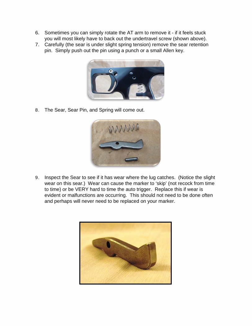
6. Sometimes you can simply rotate the AT arm to remove it - if it feels stuck you will most likely have to back out the undertravel screw (shown above).
7. Carefully (the sear is under slight spring tension) remove the sear retention pin. Simply push out the pin using a punch or a small Allen key.
8. The Sear, Sear Pin, and Spring will come out.
9. Inspect the Sear to see if it has wear where the lug catches. (Notice the slight wear on this sear.) Wear can cause the marker to ‘skip’ (not recock from time to time) or be VERY hard to time the auto trigger. Replace this if wear is evident or malfunctions are occurring. This should not need to be done often and perhaps will never need to be replaced on your marker.

10. Remove the Trigger Shoulder Bolt and slide the trigger from the frame (shown with the top Allen key). Be sure not to over tighten the Trigger Shoulder Bolt. Over tightening can cause drag on the trigger.
11. Your trigger frame is now completely disassembled. Clean thoroughly and reassemble.
Chassis Disassembly and Maintenance:
1. Remove the feedneck by unscrewing it from the Feedneck Mounting Adapter.
2. Remove the two Feedneck Mounting Adapter Screws with a 5/64th Allen Key

3. Remove the Bolt Pin, and bolt. 4. Remove the back block by using the T-10 Torx screws on the back block.
The back block is countersunk in two spots to allow the pump arms to slide into the back block. This can cause the back block to feel stuck. Be patient and carefully remove the back block. I find moving the pump forward puts even pressure on the back block and can help finesse the back block off the pump arms.
Note: Be very careful when replacing these screws. Use blue loc-tite and do not over tighten. Finger tight allows for smooth movement of the backblock and bolt. Over tightening of the back block screws can cause binding once the bolt is installed.
5. Slide the Pump Handle and Pump Arms off the marker. 6. Use 3/16th Allen Key to remove the Pump Rod. On the Series 5 Basic the
Pump Arm Guide Ring will come with it.
7. Remove Vertical Regulator Adaptor (VRA). This may be held on with Loctite® and thus you may need to use some heat to remove it. I have never had to use heat, and this part never has to be removed, so be careful and do not strip the bolt.

8. The VRA has one static o-ring – which I lightly lubricate (Dow 55)upon reassembly.
9. Remove the two screws that affix the top tube (breach) to the bottom tube. These are T10 Torx Screws. These are held on with blue loc-tite and should be replaced with blue Loctite. The Ball Detent will also come out at this point (shown here red).

10. Note the depth of the Lug before disassembly. You want to replicate this depth upon reassembly. It will make timing the marker much easier.
This is a Series 5 – but the principle is the same.
11. Remove the Bottom Tube Cap with a ¼ Allen key.
12. Remove the IVG from the marker (3/16thth Allen Key) noting its depth from flush to the rear of the body. About 3 turns are normal. The main spring will also come out at this point.

13. Insert a 1/8th Allen key into the lug and turn it until it is flush with the hammer. This allows for the removal of the hammer.
14. Remove the Valve Retaining Screw and the Valve Retaining Nut Set Screw from the bottom of the marker.
Cutaway view showing removal of Valve Retaining Nut Screw.
Cutaway view showing removal Valve Retaining Nut Set Screw.
15. Insert an Autococker® Valve Tool into the rear of the bottom tube until you feel it seat deeply on the Valve Retaining Nut and remove it. Because

CCM® uses a Valve Retaining Nut Set Screw; the Valve Retaining Nut is often marred. This can make this nut a bit stiff to remove. Take your time, make sure the tool is seated as deeply as it can be, and be careful.
Cutaway showing Valve Wrench fully engaged in Valve Retaining Nut.
Cutaway showing Valve Wrench removing Valve Retaining Nut.
16. Carefully dump out the Valve, Valve Seal, and Valve Spring. Sometimes a few taps on a soft surface are necessary.
T2 Valve Set: From left to right Valve Retention Nut, Valve Body and Valve Body O-Ring, Valve Pin and Cup Seal, Valve Spring.
17. Inspect the Valve Seal. If it appears damaged – replace it. These can last a very long time, but dirt and other debris can cause them to fail. If your marker is leaking down the barrel (and the cause is not the pressure of the marker being too low) it may be a bad Valve Seal.
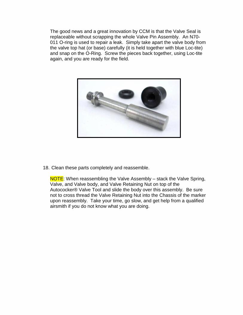
The good news and a great innovation by CCM is that the Valve Seal is replaceable without scrapping the whole Valve Pin Assembly. An N70-011 O-ring is used to repair a leak. Simply take apart the valve body from the valve top hat (or base) carefully (it is held together with blue Loc-tite) and snap on the O-Ring. Screw the pieces back together, using Loc-tite again, and you are ready for the field.
18. Clean these parts completely and reassemble.
NOTE: When reassembling the Valve Assembly – stack the Valve Spring, Valve, and Valve body, and Valve Retaining Nut on top of the Autococker® Valve Tool and slide the body over this assembly. Be sure not to cross thread the Valve Retaining Nut into the Chassis of the marker upon reassembly. Take your time, go slow, and get help from a qualified airsmith if you do not know what you are doing.
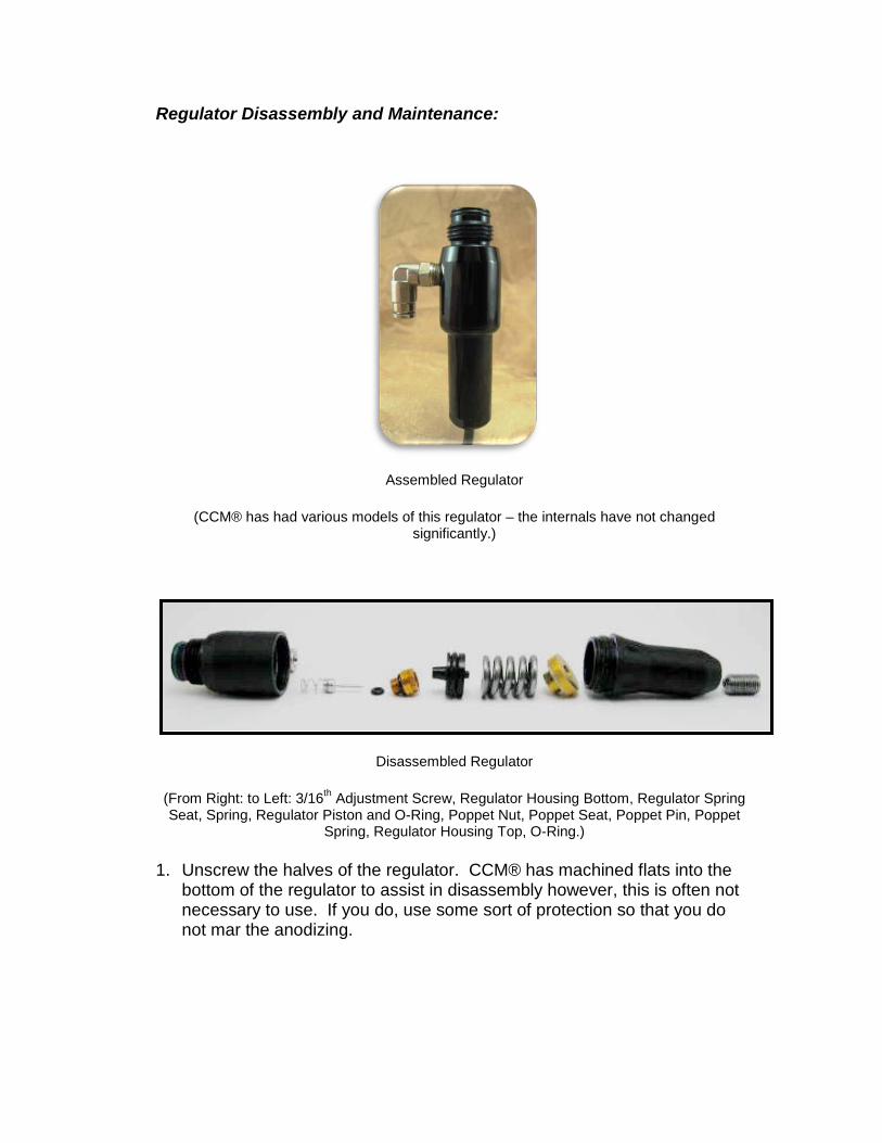
Regulator Disassembly and Maintenance:
Assembled Regulator
(CCM® has had various models of this regulator – the internals have not changed significantly.)
Disassembled Regulator
(From Right: to Left: 3/16th Adjustment Screw, Regulator Housing Bottom, Regulator Spring Seat, Spring, Regulator Piston and O-Ring, Poppet Nut, Poppet Seat, Poppet Pin, Poppet
Spring, Regulator Housing Top, O-Ring.)
1. Unscrew the halves of the regulator. CCM® has machined flats into the bottom of the regulator to assist in disassembly however, this is often not necessary to use. If you do, use some sort of protection so that you do not mar the anodizing.

2. Use a 5/16th Allen Key to remove the Regulator Pin Retainer.
3. Carefully dump out the rest of the pieces from the top of the regulator.

4. Clean (use your Q-tips® in all the appropriate places on the regulator top) and replace the regulator Pin O-Ring if necessary. Apply a light coat of oil to these parts and replace them.
5. Take the Velocity Adjustment Screw out of the bottom and push the Top Hat, Spring, and Piston from the top with a long Allen Key.
6. Clean the bottom portion and replace the Regulator piston or Regulator Piston O-Ring if necessary.
7. CCM® packs the lower portion Hater Sauce. I have found no grease is necessary here and simply apply a coat of Dow® 55 or Hater Sauce on the Piston and Piston O-Ring.
8. Put the regulator bottom back together and screw in the 3/16th two turns in from flush of the base of the regulator.
9. Reassemble the regulator and check it. I use a simply pressure testing kit. Set the Regulator at 300 PSI. If not simply follow the set up instructions above.

XIII. Pimpin’ Your ‘Ride’:
There is very little one can do to either of these markers to improve their performance. Both come with delrin bolts, polished and lightly sprung internals, and a good pump kit. However, I have experimented with trying to squeeze a little more performance out of both since I have owned them. I will start with what is a waste of money and time and then move on to the few modifications that seem to work.
What Not To Buy:
Regulator:
The regulator that comes with the CCM® is essentially a Torpedo® style regulator. It is a tried and true design and I have had very few problems with my CCM® regulators. I have used a CCM® regulator for over two years without changing a seal and perform maintenance every few months as described above.
Barrel:
I have found that the stock barrel is a very good and accurate barrel. It comes stock with a 2” control bore at .690 Inner Diameter that opens up to .695 at the tip. If you want to match paint and have a greater flexibility in a barrel you may want to purchase additional backs for your CCM® marker. The two inch control bore, in my opinion, may not be the most efficient but it is accurate and very high quality.
A Low Pressure Tank:
I have used both 450 psi output tanks and 800 output tanks on my CCM® markers for a few years and see no difference in performance. I rarely even need to adjust my regulator to compensate for the slight difference in output from the secondary regulator when switching from tank to tank. The CCM® regulator is a 50 to 1 regulator and thus switching from a low pressure tank to a high pressure tank will only result in an 8 psi output difference at the secondary regulator. This will not make that much difference in FPS over the chronograph.
Some may argue that your regulator will work much less hard by using a high pressure tank – but I don’t think with a pump that really matters. With that said, however, I do use a low pressure tank. This is simply because I already had it when I bought my first CCM® .
Agitating Hopper:

I have found that the fastest any pump with an auto trigger can be fired tops out at about 7 balls per second. Due to the rocking motion inherent in the pumping process, a good feeding gravity hopper will work just fine. I have had no issues with a VL 200, an Empire® Hopper, or even an Ammo Box during high rates of fire. I currently use a modified Sportshot Hopper that feeds great at about 6 to 7 bps that I can achieve in rapid fire. I find that an agitating loader simply adds weight and is unnecessary.
What To Do:
Polishing:
Beside sweet spotting the regulator, buying fresh high quality paint, getting a fast feeding hopper, and a quality tank and tank regulator – you can polish the guide rod, the hammer and lug, the cocking rod, and the sear.
I use a polishing wheel (simply a polishing wheel attached to one side of a bench grinder) and I start with Non-Ferrous Rouge and finish with Jewelers’ Rouge. Non-Ferrous Rouge is gray in color and can be aggressive. Go slow and pay attention. Both markers come fairly well polished so a little can go a long way. When you get the stainless parts very shiny clean the wheel and change to the Jewelers’’ Rouge (which is deep red in color).
After achieving a mirror finish on these parts – reassemble the marker and test them out. You will notice a bit more smoothness – it won’t be miraculous – but it will be a bit faster. I touch these parts up from time to time to keep them very smooth.
Feednecks:
Also you can call CCM and get a variety of Feednecks for your T2 if you want to. They come in Mid-Rise, No-Rise, and No-Pro sizes. Also you can a feedneck to fit the smaller hoppers such as the Winchester pocket hopper.
Top Tubes:
You can also contact CCM and get a variety of Feeds for your T2. Center Feed, Right, and Left Feeds are available.
Barrel Backs:
You can get 5 more sizers from CCM to match your paint to your barrel. .679, .681, .684, .687, .690 (standard), .693

XIV. Troubleshooting:
My velocity is very erratic.
This is most often caused by inconsistent paint sizing. See if your paint fits your barrel well and consistently. If not, try better paint.
I have good paint and my velocity is still erratic.
Clean your regulator. If this still is happening – replace the seals inside the regulator.
I have good paint, my regulator is working fine, and my velocity is still erratic.
Clean the bottom tube and hammer. If some sludge builds up on the hammer it can cause drag and cause the valve to open inconsistently.
Marker leaks down the barrel when I air it up but stops once I cock it.
This is normal and caused by CCM’s use of a very light valve spring.
The light Valve Spring and heavier Main Spring force the valve open when not aired up.
This is a good thing overall and all you need to do is simply cock the marker before you air it up.
Marker leaks down the barrel after I pull the trigger but stops once I cock it again.
This is most likely caused by your Regulator Pressure being too low. Follow the set up instructions above and this should solve this problem, or set the regulator at 300 PSI and it should stop this leak.

Marker leaks down the barrel no matter what I do.
This is probably caused by a bad Valve Seal (Cup Seal). Replace this part. Sometimes you can get this leak to stop by running oil through the marker. Try this first and then replace the Valve Seal.
I took off the grip frame and now the marker won’t even pump to the cocking point.
You have the screws that hold the frame on the marker reversed and the rear screw is protruding into the bottom tube of the marker and stopping the hammer from re-cocking. Reverse these screws.
I pulled the bolt and replaced it out and now the marker won’t shoot at all and is very quiet when I pull the trigger.
You have your bolt upside down. Reverse it.
My trigger is fine but when I lean my marker to the left (as I am shooting it), the trigger either won’t move or gets very sticky.
Adjust the undertravel screw on the frame. Follow the set up instructions above. This screw stops the cam from being able to slide out of the grip frame.
I am chopping paint or getting a lot of barrel breaks.
If you are chopping paint, the most common cause of this is that your paint is too tight for the barrel of your marker. It is not causing your paint to chop it causing it to break in the barrel. Use a properly sized barrel or properly sized paint.
Your paint could simply be too brittle. I have found the CCM® markers tolerate brittle paint very well. Drop a few paintballs on the ground. If they break very easily – this is most likely your culprit. Get a more robust shelled paint.
Another common cause is that your detents are bad and you are double feeding paint. Again, you are not chopping paint but causing one ball to hit the other and break in the barrel. Replace your detents.
If you are indeed chopping paint – it is either user error (you are simply closing the breach on a ball), feed issues (your hopper is not keeping up) or your paint is horribly out of round and not fitting in the breach. Practice, get a better feeding hopper, or better paint.

The marker does not fire when I am using the auto-trigger or skips shots.
Lower the lug. Follow the setup procedures. If this does not solve the problem, it could be a worn sear. Replace the sear.
Trigger is very sticky.
Check to see that you have not over tightened the Shoulder Bolt that retains the trigger. This can cause drag on the trigger against the frame. In addition, this can be caused by simply having a dirty trigger frame.
I seem to lose velocity during higher rates of fire (Auto-Triggering).
There can be many causes of this problem. The first to check is the point at which the marker fires during auto-trigger. If it fires too soon – the bolt hole is not properly lined up with the air passage and causes the velocity to drop off during auto-trigger but not during normal shooting. Time the auto trigger (above).
A dirty regulator piston can also cause a drop off during high rates of fire due to a slow recharge rate of the regulator. Fully clean the regulator and if this is the cause – it will clear up.
One thing can cause this problem is that your tank is not recharging quickly enough and causes a ‘starving’ problem. Use a pressure gauge with slide check to test the recharge rate of your tank.
Also, oddly, a dirty hammer can cause this as well. Due to tight tolerances of the CCM marker a gummy hammer can cause drag and cause erratic velocities. Clean the bottom tube and this should clear the problem.
One last thing that causes this is a worn trigger. If you tend to mash the trigger (like I do) this can cause a serious divot in the trigger (where the AT Cam rubs on the trigger) and cause odd problems. Replace when this divot gets serious.
What feedneck threading is my marker?
CCM uses their own threads for the feedneck on the S6 and S5B.

XV. T2 Parts List
Item Material Vendor Part # Body Assembly:
Body (top and bottom) 6061 Aluminum DPM Back Block 6061 Aluminum DPM
Body - Upper Tube from the barrel:
Bolt Delrin DPM Bolt Pin 17-4 DPM
Bolt Pin O-ring Buna-N McMaster N90-009 Detent Buna-N Spyder Detent
Attachment Screws
6/32 x ¼ Torx BHTC Body - Lower Tube from the pump:
Exhaust Valve Spring Stainless Steel Lee Springs LC-028D 11 Exhaust Valve Hat 6061 Aluminum DPM
Exhaust Valve O-Ring Buna-N McMaster N70-011 Exhaust Valve Pin 6061 Aluminum DPM
Exhaust Valve Body 6061 Aluminum DPM Exhaust Valve Body O-ring Buna-N McMaster N70-011
Valve Retaining Nut 6061 Aluminum DPM Valve Alignment Screw Stainless Steel McMaster 5/16 - 24 x 1/4 SS
Valve Retaining Nut Set Screw Stainless Steel McMaster 10-32 x 3/16 SS Hammer Body Stainless Steel DPM
Hammer Sear Lug Stainless Steel Fastenal 1/4 - 28 x 5/8 SSCP (Turned at
the bottom) Hammer Nylon Set Screw Nylon Fastenal 10-32 x 3/16
Main Spring Stainless Steel
¼-28 x 5/8 SSSCP Back Cap 6061 DPM
Back Cap O-ring I.V.G 6061 Aluminum DPM
I.V.G O-ring Buna
N70-013 Pump Kit From the pump handle
Pump Handle Delrin DPM Pump handle Plate 6061 DPM Pump Plate Screws Stainless Steel Fastenal 10-32 x 1/2 FHSCS
Guide Rod 17-4 DPM Guide Rods 304 DPM Pump Arm - Drilled and Tapped Stainless Steel DPM
Back Block 6061 Aluminum DPM Back Block Screws
6-32 x 3/8 BHTC

Pump Kit Guide Screw O-Ring Buna-N McMaster N70-015 Grip Frame from the Trigger Guard.
.45 Hinge Frame 6061 Aluminum DPM Trigger Delrin DPM
Trigger Bearing H .250, W .110 Trigger Bearing Pin Steel McMaster 1/8 x 1/4 Dowel Pin
Sear Standard cocker sear Sear Pin Steel McMaster 1/8 x 1/2 Ground Pin
Sear Spring (Same as Valve Spring) Lee Springs Lee Springs LC-028D 11 Grips Delrin DPM
Grip Screws Stainless Steel Fastenal 6-32 x 1/4 ss BSHCS Frame Mounting Screw (front) Stainless Steel Fastenal 10-32 x 1/4 BHCS Frame Mounting Screw (rear) Stainless Steel Fastenal 10-38 x 3/8 LHSCS
Auto Trigger Assembly Auto Lever 6061 Aluminum DPM
Auto Lever Cam 300 Series Steel DPM Cam Pins Stainless Steel Fastenal 1/16 x .250 Ground Pins
Cam to Lever Screw Stainless Steel Fastenal 6-32 x 1/4 BSHCS Auto Lever Post 300 Series Steel DPM
Vertical Regulator Adapter (VRA) and Regulator
VRA with threaded Guide Hole 6061 Aluminum DPM VRA Screw Stainless Steel Fastenal 1/4 - 28x3/4 18-8 SHCS VRA O-Ring Buna-N McMaster N70-113
Regulator Top Housing 6061 Aluminum DPM
Regulator Top O-Ring Buna-N O-Rings
West N90-015 Poppet Nut 6061 Aluminum DPM
Poppet Nut O-Ring Buna-N McMaster N70-010 Poppet (pin) 6061 Aluminum DPM
Poppet Spring Stainless Steel McMaster LC 016C 055 Poppet Seat Buna-N McMaster N90-006
Regulator Lower Housing 6061 Aluminum McMaster Lower Housing top O-ring Buna-N McMaster N70-017
Regulator Piston Delrin DPM Regulator Piston O-ring Buna-N McMaster N70-113 Regulator Main Spring Music Wire Lee Springs Special Grind Regulator Spring Seat 6061 Aluminum DPM
Regulator Adjustment Screw Stainless Steel McMaster 3/8 - 24 x 5/8 18-8SS
Feedneck: Feedneck 6061 Aluminum DPM 7/8 x 20
Clamp Ring 6061 Aluminum DPM

Clamp Ring Screw Stainless Steel Fastenal 10-32x1/2 SCS Mounting Adapter 6061 Aluminum DPM
Rail and ASA: Rail 6061 Aluminum DPM
Mounting Screws Stainless Steel Fastenal 10-32 x 1/2 SCHMS Rail Spreading Screws Stainless Steel Fastenal 1/4 - 28 x 5/8 SSCP Side Port Plug Screw Zinc Plated McMaster 1/8 pipe plug
Knob O-ring Buna-N O-Rings
West N90-015 On-Off Body 6061 Aluminum
On-Off Shaft O-Ring Buna-N McMaster N70-008
XVI. Contact Information for CCM:
CCM / DPM 19641 N. Hirsch St
Anderson, Ca 96007 Phone- 530-378-3420 Sales- 1-877-412-6850
Fax- 530-378-3420
www.chipleymachine.com
XVII. Additions and Changes:
We will be making changes to this manual periodically as we find out more and add more information.
Please feel free to contact [email protected] with any additions, corrections, or changes.
![Chipley Banner. (Chipley, Florida) 1900-03-10 [p ]. · wept Sunda s-Mall ram OranioHlit liayhead and St AndrewS arrives at6 pm and al-r am da11v4exceptSunday ain 30ami1 am ut12msidffom5pmto8](https://static.fdocuments.us/doc/165x107/5e19cd1b50451539b818b59d/chipley-banner-chipley-florida-1900-03-10-p-wept-sunda-s-mall-ram-oraniohlit.jpg)


![Chipley Banner. (Chipley, Florida) 1900-04-28 [p ].chroniclingamerica.loc.gov/lccn/sn95047263/1900-04-28/ed-1/seq-4.pdf · ems rrrrI- c A Mothers Tears 1 Would Cry Evory Time I Washed](https://static.fdocuments.us/doc/165x107/5eccadf9a0af283cb576dfe2/chipley-banner-chipley-florida-1900-04-28-p-ems-rrrri-c-a-mothers-tears.jpg)

![Chipley Banner. (Chipley, Florida) 1898-02-12 [p ].ufdcimages.uflib.ufl.edu/UF/00/07/58/91/00036/0235.pdfTea miDst I The Times of India declares that tea drlklng Is the curse of Thibet](https://static.fdocuments.us/doc/165x107/60f84631c0ecca6ff71cf0ee/chipley-banner-chipley-florida-1898-02-12-p-tea-midst-i-the-times-of-india.jpg)

![Chipley Banner. (Chipley, Florida) 1898-06-11 [p ].ufdcimages.uflib.ufl.edu/UF/00/07/58/91/00053/0341.pdf · nbrr 1 1Y- L I r- 4t rTtI I r I 11 s 9 LlghtLonio Keeper How far off from](https://static.fdocuments.us/doc/165x107/5f06f2897e708231d41a87e6/chipley-banner-chipley-florida-1898-06-11-p-nbrr-1-1y-l-i-r-4t-rtti-i.jpg)
![Chipley Banner. (Chipley, Florida) 1912-10-24 [p ]....writeup Robertson Piano delivery Lawrence pleasant Trammell business qualified Millville Tuesday Democrat Clt American exhibits](https://static.fdocuments.us/doc/165x107/5e53ca233648f336864a6663/chipley-banner-chipley-florida-1912-10-24-p-writeup-robertson-piano.jpg)
![Chipley Banner. (Chipley, Florida) 1900-03-17 [p ].ufdcimages.uflib.ufl.edu/UF/00/07/58/91/00145/0769.pdf · 2009. 5. 15. · If you will put from one I i fourth to half a tcaspoohful](https://static.fdocuments.us/doc/165x107/603febcec996e83bc572a576/chipley-banner-chipley-florida-1900-03-17-p-2009-5-15-if-you-will-put.jpg)


