University of Minnesota Dimensions • Length 122.75 inches • Diameter 6.160 inches • Weight...
26
University of Minnesota NASA USLI Presentation 10-29-2012 University of Minnesota: 2012-2013 USLI Preliminary Design Review 1
Transcript of University of Minnesota Dimensions • Length 122.75 inches • Diameter 6.160 inches • Weight...

University of Minnesota
NASA USLI Presentation 10-29-2012
University of Minnesota: 2012-2013 USLI Preliminary Design Review 1
Objectives
• Design a rocket to reach apogee at 1 mile • Deploy a drogue and main chute • Deploy a payload on the ground • Remain Subsonic • Design a Re-usable Modular system
University of Minnesota: 2012-2013 USLI Preliminary Design Review 2
Rocket Design
• Key Components Payload bay section Pressure tank section Air-pressure airbrakes Modular fin system Modular motor mount system
University of Minnesota: 2012-2013 USLI Preliminary Design Review 3
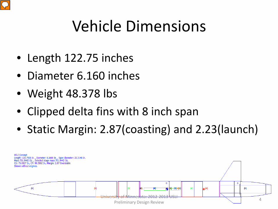
Vehicle Dimensions
• Length 122.75 inches • Diameter 6.160 inches • Weight 48.378 lbs • Clipped delta fins with 8 inch span • Static Margin: 2.87(coasting) and 2.23(launch)
University of Minnesota: 2012-2013 USLI Preliminary Design Review 4
Presenter
Presentation Notes
Air brakes move cp hence greater static margin
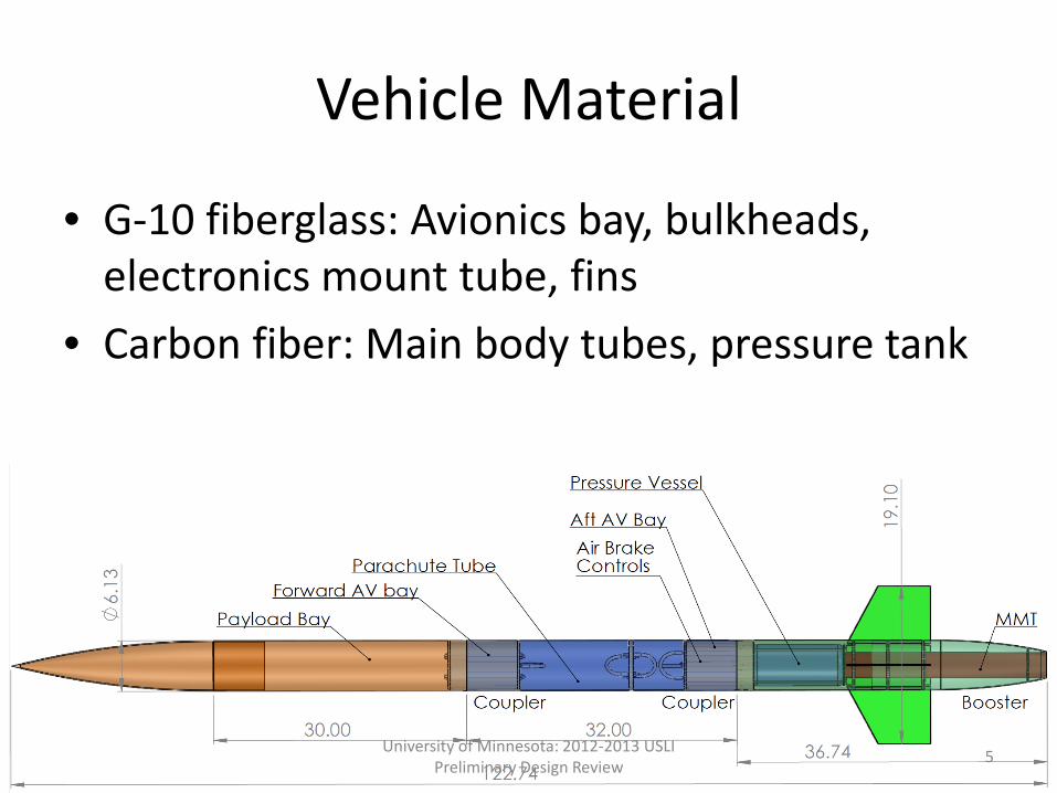
Vehicle Material
• G-10 fiberglass: Avionics bay, bulkheads, electronics mount tube, fins
• Carbon fiber: Main body tubes, pressure tank
University of Minnesota: 2012-2013 USLI Preliminary Design Review 5
Components that will be stress tested
• Body Tubes • Piston • Pressure Vessel Mount • Motor mount • Bulkheads • Fins • Shear pins
University of Minnesota: 2012-2013 USLI Preliminary Design Review 6
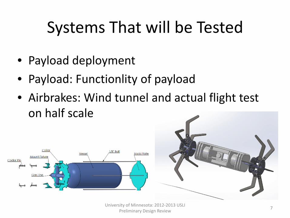
Systems That will be Tested
• Payload deployment • Payload: Functionlity of payload • Airbrakes: Wind tunnel and actual flight test
on half scale
University of Minnesota: 2012-2013 USLI Preliminary Design Review 7
Motor Selection
• Motor Size constraints: 75mm motor • Need motor to slightly overshoot 5,280 ft • Cessaroni Pro75 4-Grain L : 4687.94 N-s • Exit rail velocity: 71.9076 ft/s • Stability out of the railing • Thrust to weight: 11.247
University of Minnesota: 2012-2013 USLI Preliminary Design Review 8
Presenter
Presentation Notes
Less than max impulse and fits
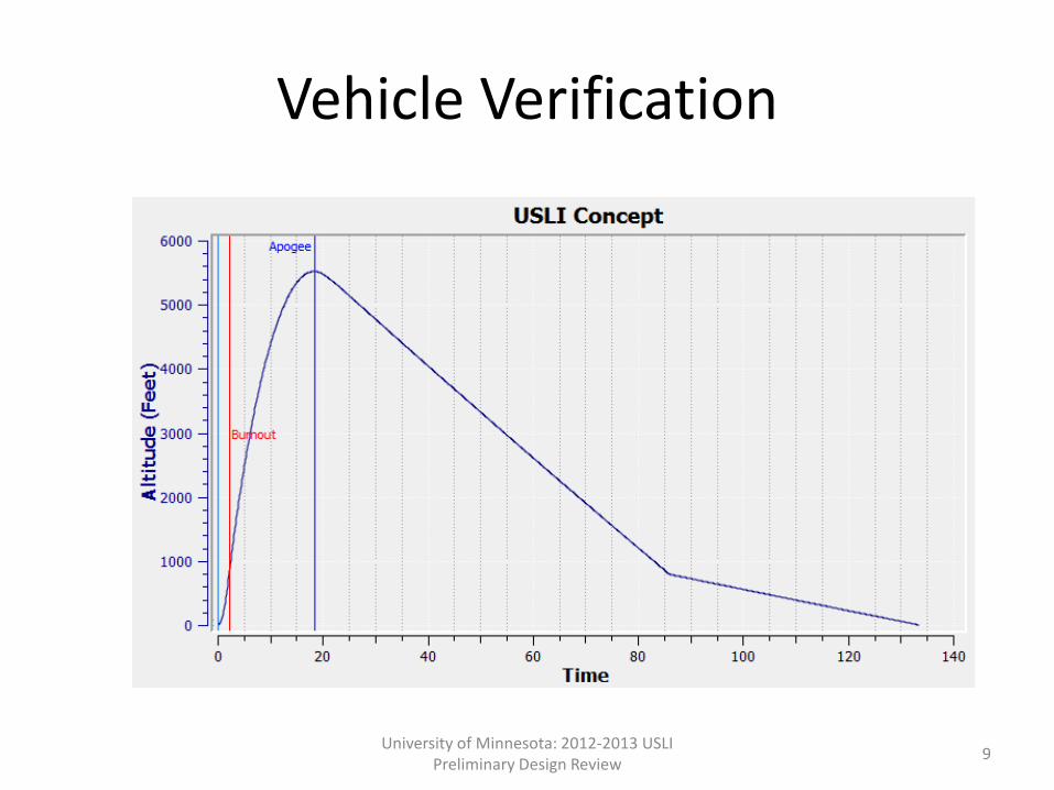
Vehicle Verification
University of Minnesota: 2012-2013 USLI Preliminary Design Review 9

Performance Characteristics
University of Minnesota: 2012-2013 USLI Preliminary Design Review 10
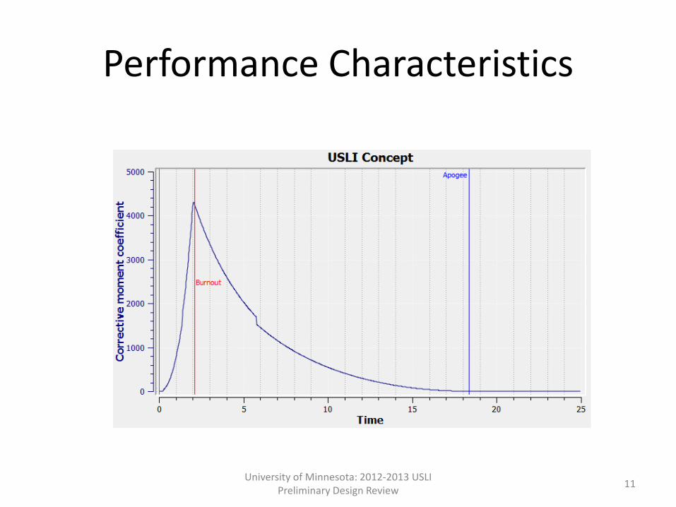
Performance Characteristics
University of Minnesota: 2012-2013 USLI Preliminary Design Review 11
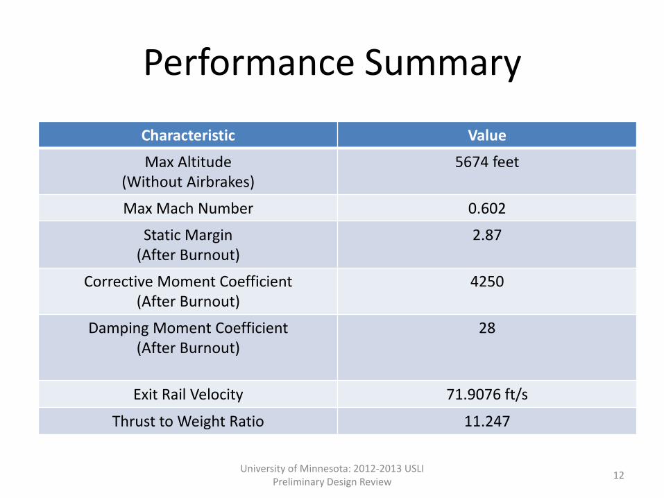
Performance Summary
Characteristic Value
Max Altitude (Without Airbrakes)
5674 feet
Max Mach Number 0.602
Static Margin (After Burnout)
2.87
Corrective Moment Coefficient (After Burnout)
4250
Damping Moment Coefficient (After Burnout)
28
Exit Rail Velocity 71.9076 ft/s
Thrust to Weight Ratio 11.247
University of Minnesota: 2012-2013 USLI Preliminary Design Review 12
Half Scale Testing
Examine manufacturing and assembly process Verify Simulation with results Confirm Recovery System Confirm Effectiveness of airbrake system
University of Minnesota: 2012-2013 USLI Preliminary Design Review 13
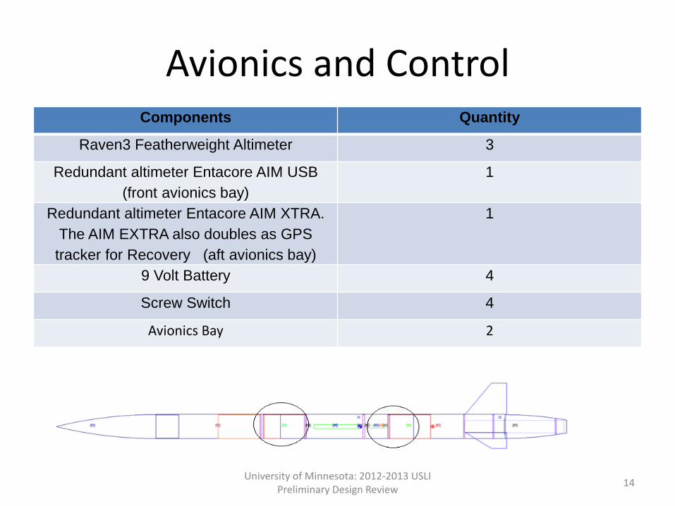
Avionics and Control Components Quantity
Raven3 Featherweight Altimeter 3
Redundant altimeter Entacore AIM USB (front avionics bay)
1
Redundant altimeter Entacore AIM XTRA. The AIM EXTRA also doubles as GPS tracker for Recovery (aft avionics bay)
1
9 Volt Battery 4
Screw Switch 4
Avionics Bay 2
University of Minnesota: 2012-2013 USLI Preliminary Design Review 14
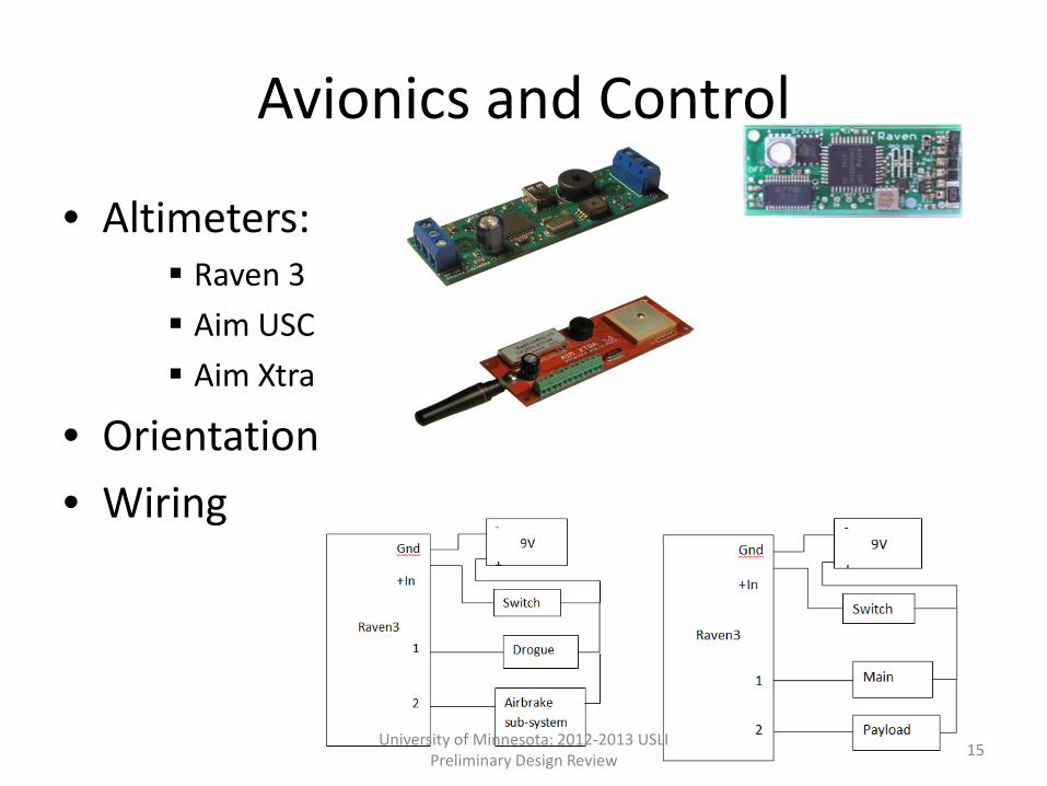
Avionics and Control
• Altimeters: Raven 3 Aim USC Aim Xtra
• Orientation • Wiring
University of Minnesota: 2012-2013 USLI Preliminary Design Review 15
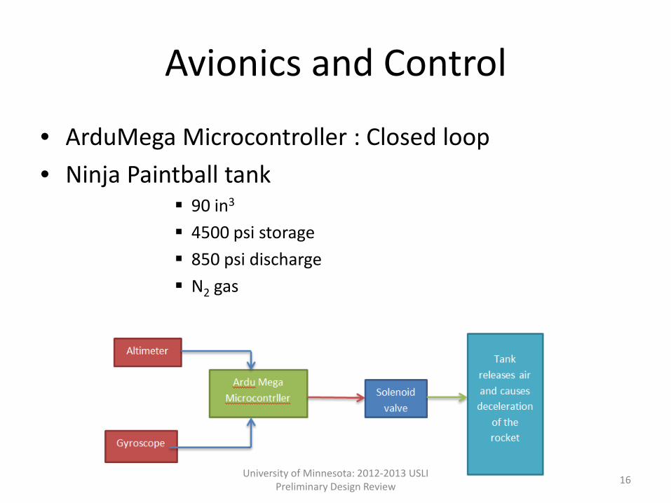
Avionics and Control
• ArduMega Microcontroller : Closed loop • Ninja Paintball tank
90 in3 4500 psi storage 850 psi discharge N2 gas
University of Minnesota: 2012-2013 USLI Preliminary Design Review 16
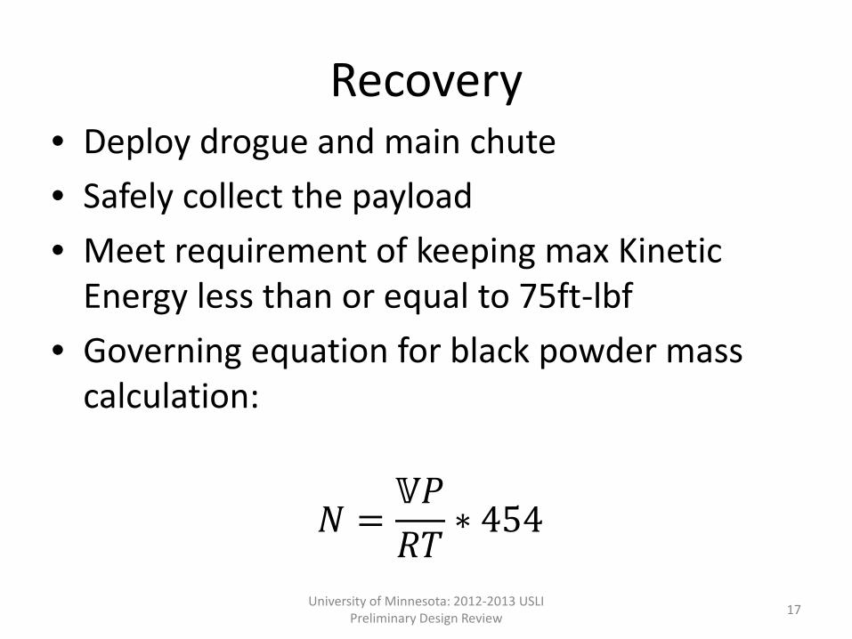
Recovery • Deploy drogue and main chute • Safely collect the payload • Meet requirement of keeping max Kinetic
Energy less than or equal to 75ft-lbf • Governing equation for black powder mass
calculation:
𝑁 =𝕍𝕍𝑅𝑅
∗ 454
University of Minnesota: 2012-2013 USLI Preliminary Design Review 17
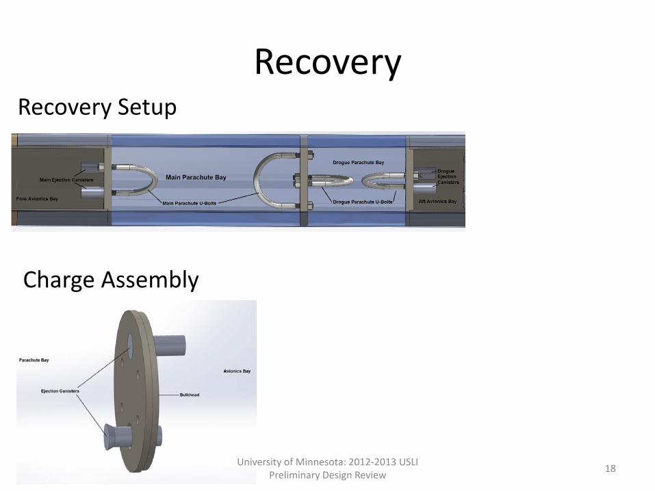
Recovery Recovery Setup
Charge Assembly
University of Minnesota: 2012-2013 USLI Preliminary Design Review 18
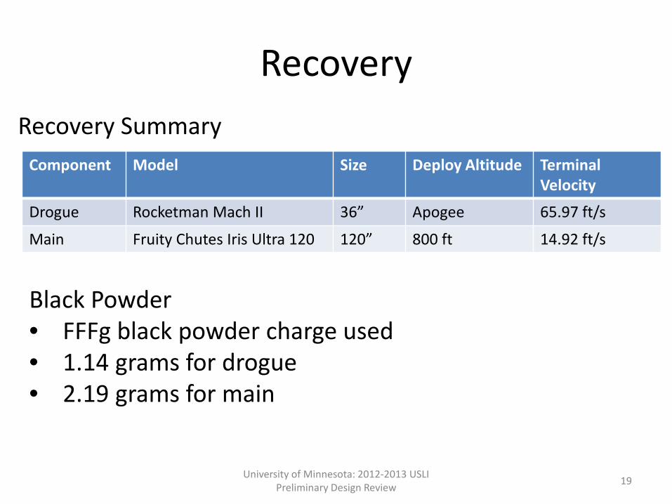
Recovery
Component Model Size Deploy Altitude Terminal Velocity
Drogue Rocketman Mach II 36” Apogee 65.97 ft/s
Main Fruity Chutes Iris Ultra 120 120” 800 ft 14.92 ft/s
Recovery Summary
Black Powder • FFFg black powder charge used • 1.14 grams for drogue • 2.19 grams for main
University of Minnesota: 2012-2013 USLI Preliminary Design Review 19
University of Minnesota: 2012-2013 USLI Preliminary Design Review 20

Payload Mission Overview
• Simulate deployment of extraterrestrial body • Receive inputs from a ground controller and to
move according to the controllers command • To execute certain autonomous comands
University of Minnesota: 2012-2013 USLI Preliminary Design Review 21
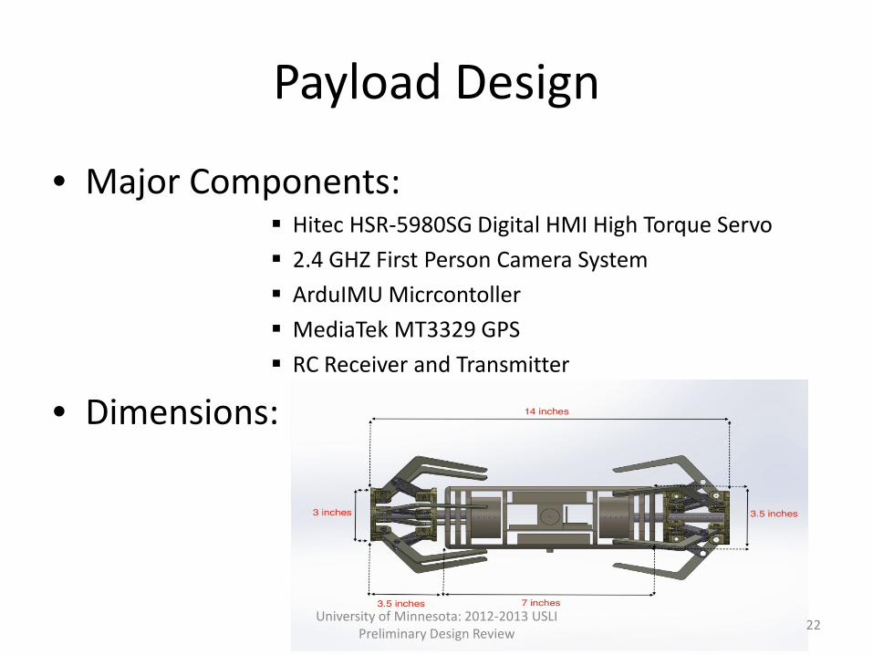
Payload Design
• Major Components: Hitec HSR-5980SG Digital HMI High Torque Servo 2.4 GHZ First Person Camera System ArduIMU Micrcontoller MediaTek MT3329 GPS RC Receiver and Transmitter
• Dimensions:
University of Minnesota: 2012-2013 USLI Preliminary Design Review 22
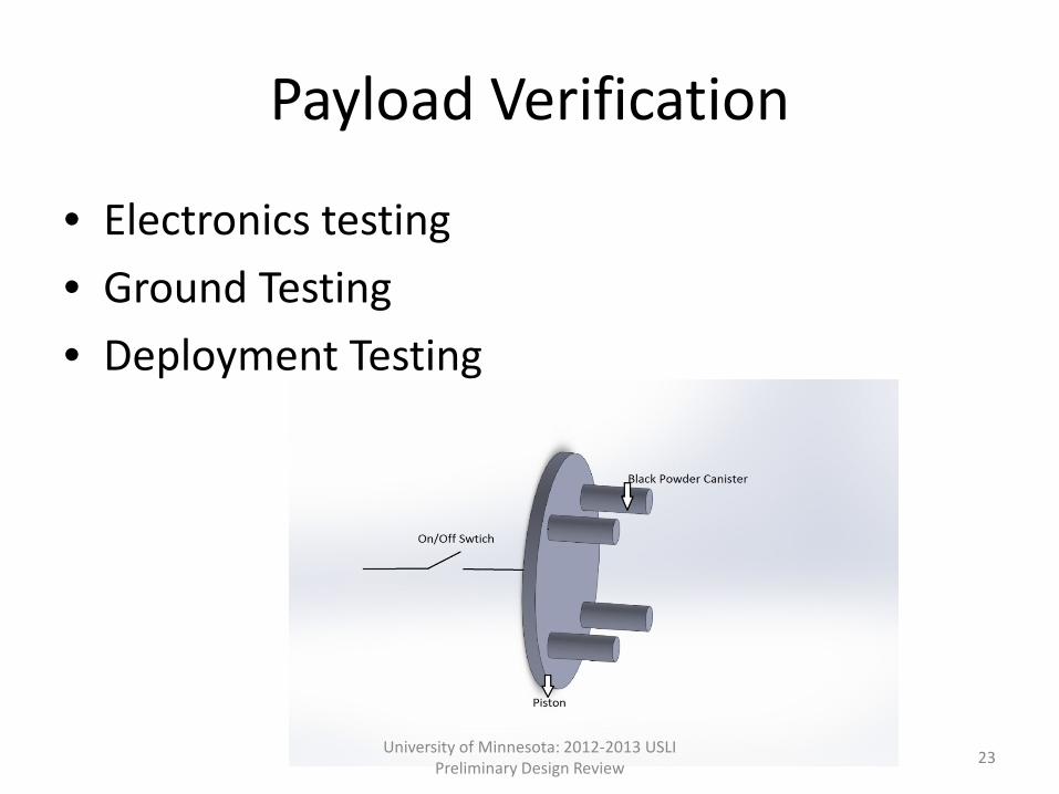
Payload Verification
• Electronics testing • Ground Testing • Deployment Testing
University of Minnesota: 2012-2013 USLI Preliminary Design Review 23
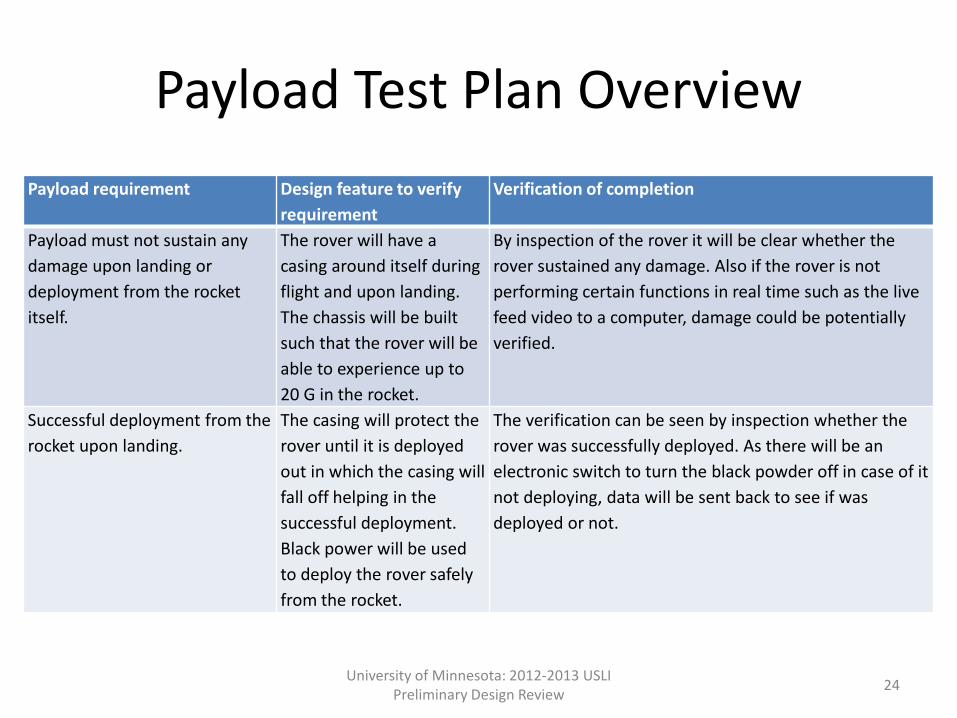
Payload Test Plan Overview Payload requirement Design feature to verify
requirement Verification of completion
Payload must not sustain any damage upon landing or deployment from the rocket itself.
The rover will have a casing around itself during flight and upon landing. The chassis will be built such that the rover will be able to experience up to 20 G in the rocket.
By inspection of the rover it will be clear whether the rover sustained any damage. Also if the rover is not performing certain functions in real time such as the live feed video to a computer, damage could be potentially verified.
Successful deployment from the rocket upon landing.
The casing will protect the rover until it is deployed out in which the casing will fall off helping in the successful deployment. Black power will be used to deploy the rover safely from the rocket.
The verification can be seen by inspection whether the rover was successfully deployed. As there will be an electronic switch to turn the black powder off in case of it not deploying, data will be sent back to see if was deployed or not.
University of Minnesota: 2012-2013 USLI Preliminary Design Review 24
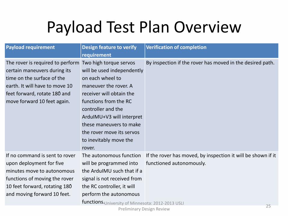
Payload Test Plan Overview Payload requirement Design feature to verify
requirement Verification of completion
The rover is required to perform certain maneuvers during its time on the surface of the earth. It will have to move 10 feet forward, rotate 180̊ and move forward 10 feet again.
Two high torque servos will be used independently on each wheel to maneuver the rover. A receiver will obtain the functions from the RC controller and the ArduIMU+V3 will interpret these maneuvers to make the rover move its servos to inevitably move the rover.
By inspection if the rover has moved in the desired path.
If no command is sent to rover upon deployment for five minutes move to autonomous functions of moving the rover 10 feet forward, rotating 180̊ and moving forward 10 feet.
The autonomous function will be programmed into the ArduIMU such that if a signal is not received from the RC controller, it will perform the autonomous functions.
If the rover has moved, by inspection it will be shown if it functioned autonomously.
University of Minnesota: 2012-2013 USLI Preliminary Design Review 25
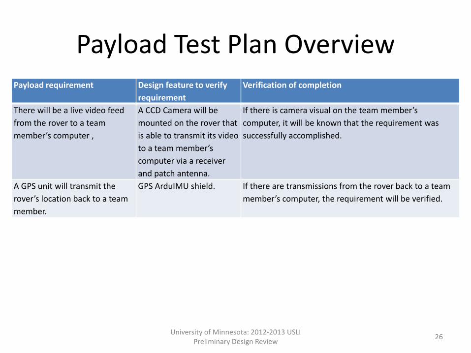
Payload Test Plan Overview Payload requirement Design feature to verify
requirement Verification of completion
There will be a live video feed from the rover to a team member’s computer ,
A CCD Camera will be mounted on the rover that is able to transmit its video to a team member’s computer via a receiver and patch antenna.
If there is camera visual on the team member’s computer, it will be known that the requirement was successfully accomplished.
A GPS unit will transmit the rover’s location back to a team member.
GPS ArduIMU shield. If there are transmissions from the rover back to a team member’s computer, the requirement will be verified.
University of Minnesota: 2012-2013 USLI Preliminary Design Review 26