University of Louisville Physical Plant
48
0 University of Louisville Physical Plant Control of Hazardous Energy LOCKOUT/TAGOUT Revised 1-1-2012
Transcript of University of Louisville Physical Plant
0
University of Louisville
Physical Plant
Control of Hazardous Energy
LOCKOUT/TAGOUT
Revised 1-1-2012

1
Control of Hazardous Energy Index
1. Introduction --------------------------------------------------------------------- Page 2 2. Regulatory Authority ---------------------------------------------------------- Page 2 3. Scope ----------------------------------------------------------------------------- Page 2 4. Program Summary ------------------------------------------------------------- Page 3 5. Procedures ----------------------------------------------------------------------- Page 3 6. Equipment ----------------------------------------------------------------------- Page 6 7. Training -------------------------------------------------------------------------- Page 7 8. Record Keeping ----------------------------------------------------------------- Page 8 9. Responsibilities ----------------------------------------------------------------- Page 8 10. Exemption of Specific Procedures ------------------------------------------- Page 10 11. Appendix A – Definitions ----------------------------------------------------- Page 14 12. Appendix B – Energy Control Procedure Template ----------------------- Page 16 13. Appendix C – Energy Control Procedure Review Form ------------------ Page 18 14. Appendix D – Supervisory Lock and Tag Removal Form ---------------- Page 19 15. LO/TO – 01 – Gas Fired Domestic Hot Water Heats ---------------------- Page 20 16. LO/TO – 02 – Domestic Hot Water Return Pumps ------------------------ Page 22 17. LO/TO – 03 – Sump Pumps Sewage Lift Station Pumps ----------------- Page 24 18. LO/TO – 04 – Auto Claves ---------------------------------------------------- Page 26 19. LO/TO – 05 – Pumps ----------------------------------------------------------- Page 31 20. LO/TO – 06 – Air Compressors ----------------------------------------------- Page 35 21. LO/TO – 07 – Multi-Fan Air Handler Units (AHUs) ---------------------- Page 41 22. LO/TO – 08 – Boilers ----------------------------------------------------------- Page 45
2
I. INTRODUCTION
The University of Louisville Physical Plant’s Control of Hazardous Energy [ Lockout/Tagout (LO/TO)] Program designates practices and procedures to prevent injury to employees who service or maintain machines and equipment capable of unexpected energizing, startup, or release of stored energy. Such equipment must be locked and tagged-out or tagged-out prior to conducting service or maintenance. Lockout devices are designed to form a physical barrier between the equipment and its energy source thereby preventing operation and are used in conjunction with tagout devices. Some equipment, particularly older equipment, may not be designed to accommodate a lockout device. In such cases, warning tags, also referred to as tagout devices, are affixed to the equipment to alert people not to energize the equipment. Tagout devices, when used alone, do not physically prevent accidental start-up and are used only as a last resort. The terms “equipment” and “machines” have broad meanings in the context of this document and are used interchangeably. While it is common to think of equipment and machines as having an electrical energy source, they may be associated with other types of energy sources including hydraulics, pneumatics, mechanical, gravity, thermal, chemical, fluids and gases, water under pressure, or steam. The terms “service” and “maintenance” are also used interchangeably for the purposes of this document.
II. REGULATORY AUTHORITY
The Physical Plant’s Control of Hazardous Energy Program is designed to ensure compliance with the Federal Occupational Safety and Health Administration (OSHA) standards on the Control of Hazardous Energy, 29 CFR 1910.147 (General Industry Standard).
III. SCOPE
The focus of the Physical Plant’s Control of Hazardous Energy Program is equipment/machines. In the case of certain equipment or machines, additional LO/TO requirements may apply under other OSHA standards (i.e., cranes/hoists, cement finishing tools, etc.). The Physical Plant’s Control of Hazardous Energy Program applies to all Physical Plant employees who service or maintain University machinery or equipment, as well as contractors hired by the University. Examples of equipment that may be subject to the Physical Plant’s Control of Hazardous Energy Program during service, maintenance, or set-up configuration changes are listed below. This list is demonstrative – it is not inclusive.
• Condensate lines. • Power tools such as lathes, saws, presses. • Elevators. • HVAC systems. • Pneumatic tools. • Miscellaneous fans, motors, etc.

3
Not all equipment or machines are subject to the full requirements of this program. In general, a piece of equipment that does not store energy and that can readily be disconnected from its energy source (i.e., key removed, unplugged, etc.) is not subject to the requirements of this Control of Hazardous Energy Program (Section X). IV. PROGRAM SUMMARY
Under the provisions of the Physical Plant’s Control of Hazardous Energy Program, certain requirements must be met prior to servicing or repairing certain equipment. In particular, employees and/or their supervisors are required to follow established generic procedures or develop equipment-specific, written energy control procedures (Section V), participate in training (Section VII), and ensure that periodic inspections of energy control procedures are performed and documented (Section VIII). Employees and their supervisors must also be familiar with other elements of the program such as the requirements for work conducted on covered equipment by outside contractors, group LO/TO procedures when service or maintenance activities are performed by a crew, craft, department, or other group (Section V), responsibilities (Section IX), and exemptions to the Control of Hazardous Energy (Section X). Additional instruction/guidance material is contained in the appendices, which include definitions (Appendix A), energy control procedure template (Appendix B), and energy control procedure review form (Appendix C). V. PROCEDURES
Two general and five specific supplemental LO/TO procedures are discussed in this section. The two general procedures, which address most tasks/equipment encountered at Physical Plant, provide instructions for single-point Lockouts and Tagouts. These general procedures, depending on specific circumstances, may need to be modified by incorporating specific procedures related to group Lockout/Tagout, work by outside contractors, Lockout/Tagout during shift or personnel changes, and removal of another employee’s lock. Where multiple-point Lockouts or Tagouts are necessary, written equipment-specific procedures must be developed and implemented by authorized employees and their supervisors. All procedures, including the general procedures described below and equipment-specific procedures must include the following steps:
1) Communicate with affected employees and prepare for shut-down; 2) Shutdown the machine/equipment; 3) Disconnect or isolate the machine from its hazardous energy source(s); 4) Apply the Lockout or Tagout device(s) to the energy-isolating device(s); 5) Release, restrain, or otherwise render safe all potential hazardous stored or residual energy; and if the possibility exists for re-accumulation of hazardous energy, regularly verify during the service and maintenance that such energy has not re-accumulated to hazardous levels; 6) Verify the isolation and de-energization of the machine; complete the service or maintenance required; 7) Communicate with affected employees and prepare for returning the machine to service.

4
A. Specific Procedures
1. Multiple-Point Lockout or Tagout
Equipment-specific, written procedures will be developed and implemented for equipment with multiple isolation points or that otherwise does not meet the conditions for single-point lockout or tagout. The written procedure must identify all the hazardous energy sources for the equipment or machine, and the technique(s) required to isolate each source. An authorized employee or their supervisor must develop the procedure. If developed by an authorized employee, their supervisor must approve the procedure. The Energy Control Procedures Template in Appendix B can be used to develop and document the procedure. A copy of the machine or equipment specific, written procedures will be maintained on file in the office of the developing department, a copy forwarded to the Manager of Safety and a copy affixed to the applicable machine or equipment. (Examples: Boilers, Autoclaves)
2. Group Lockout or Tagout This supplemental procedure is applicable when more than one employee will be simultaneously servicing the same piece of equipment. Equipment-specific, written procedures must be developed and implemented for a group lockout. The written procedure must identify all hazardous energy sources for the equipment or machine, and the technique(s) required to isolate each source. An authorized employee or their supervisor must develop the procedure. If developed by an authorized employee, their supervisor must approve the procedure. The Energy Control Procedures Template in Appendix B can be used to develop and document the procedure. The general process that must be followed is described below and must be incorporated into the written, equipment-specific procedure. An authorized employee, designated by the supervisor, shall inform affected employees that
service or maintenance is required on the equipment and that it must be shutdown, locked out, and tagged.
The designated authorized employee will shut down the equipment using the normal shutdown procedures (i.e., activate the stop button, open the switch, close the valves, etc.). Specific shut-down operations should be described in the written procedure.
The designated authorized employee will isolate all sources of energy (i.e., turn off the breaker; apply blind flanges on a pipe, etc.). Specific energy sources and isolation operations should be described in the written procedure.
The designated authorized employee will attach a group lock and tag on each isolation point.
The designated authorized employee will place a copy of the procedure and the key to the group locks into a lockbox under the supervision of at least one other authorized employee or supervisor. The designated authorized employee will then place a hasp and tag on the lockbox and place their employee lock on the hasp.

5
The designated authorized employee will test the equipment to verify the effectiveness of the lockout device, if applicable. Specific test procedures should be described in the equipment-specific lockout/tagout procedure.
Each authorized employee should visually inspect the isolation of the equipment and when satisfied that it is correctly and safely isolated, place their lock on the hasp prior to beginning work. When an authorized employee completes their work, they are responsible for removing their lock from the lockbox.
When the equipment is ready to be returned to service the designated authorized employee should check the equipment and the immediate area to ensure that nonessential items have been removed, that all components are operationally intact, and that all guards or other protective features are restored.
The designated authorized employee will check the work area to ensure that all personnel are safely positioned away from the equipment.
The designated authorized employee will verify that the controls are in the neutral, off, or safe position.
All authorized employees will remove their locks from the lockbox.
The designated authorized employee will remove their lock, the group locks, and associated tags, and then re-energize the equipment.
The designated authorized employee will notify affected employees that work is completed and the equipment is ready to be returned to service.
3. Contractors
Outside contractors or vendors performing service, maintenance, and/or construction work at University of Louisville are required to follow the Physical Plant’s Lockout/Tagout Program. Departments that hire and supervise contractors directly are responsible to verify compliance with this requirement (i.e., equipment or service maintenance contracts).
Note: Other information may need to be exchanged at this time (i.e., Chemical Safety, Confined Space Program, etc.)
When outside service personnel (i.e., independent contractors or service vendors) are to be engaged in a group lockout with Physical Plant employees, Physical Plant authorized employees will follow the Physical Plant’s Control of Hazardous Energy (Lockout/Tagout) Program for group lockouts and contractors will apply their locks to the lockbox hasp. Communication between/among groups must take place to ensure all affected and authorized employees are protected.

6
4. Shift or Personnel Changes To maintain continuity in the protection provided for those involved in the lockout/tagout procedures, and for the orderly transfer of the lockout/tagout devices, the steps below are necessary during personnel or shifts changes.
Personnel Changes. The arriving authorized employee's lock and tag should be applied before the departing authorized employee's lock and tag are removed. The departing personnel will inform the arriving personnel of the status of the equipment and the work in progress.
Group Lockout Shift Changes. The lock and tag of at least one authorized employee on the arriving shift should be applied before the last crewmember of the departing crew removes their lock. The departing crew will inform the arriving crew of the status of the equipment and the work in progress.
5. Removal of Another Employee’s Lock
When the authorized employee who applied the lockout devices and associated tags is not available to remove them, the devices may be removed by the authorized employee's supervisor in accordance with the process described below:
The authorized employee's supervisor must verify that the authorized employee
who applied the lockout device(s) and associated tag(s) is not on duty and that their work is no longer in progress by taking all reasonable efforts to contact the authorized employee to inform him/her that the devices need to be removed.
Complete Supervisory Lock and Tag Removal Form – Appendix D
An authorized employee/supervisor returns the equipment to service and notifies the affected employees that service or maintenance is completed and the equipment is ready for use.
When the employee returns to work, the supervisor notifies him/her that their lock(s) and tag(s) were removed.
VI. EQUIPMENT
A. Protective Materials and Hardware
Locks and tags used for lockout/tagout must be easily recognizable as locks or tags used for lockout/tagout purposes. Locks must be either a different color, shape, or size than locks used for any other purpose within the department. Tags should be plastic; red, white, and black in color; and labeled with the words “Danger, Do Not Operate,” or equivalent.

7
Supervisors are responsible for providing authorized employees under their supervision with locks and tags and any special chains, wedges, key blocks, adapter pins, self-locking fasteners, or other hardware required for isolating, securing, or blocking equipment from energy sources. These materials must be of durable construction and capable of withstanding the conditions in which they are placed.
B. Lockable Energy-Isolating Device Installation
Whenever possible, equipment that is not capable of receiving a lockout device should be retrofitted to accommodate a lock. Newly purchased equipment must be capable of accommodating a lockout device.
VII. TRAINING
A. Authorized Employees and their Supervisors
The Manager of Safety will provide initial orientation training for new employees, as well as arranging annual training, as needed, on the requirements of the Physical Plant’s Control of Hazardous Energy (Lockout/Tagout) Program. This training will also include information on the recognition of applicable hazardous energy sources, the type and magnitude of the energy available in the workplace, and the methods and means available for energy isolation and control. Supervisors must supplement this general training with equipment-specific training for
authorized employees under their direction.
B. Equipment Specific Lockout/Tagout Training
Supervisors are responsible for providing equipment-specific lockout/tagout procedures, as well as associated employee training. Equipment-specific training can be accomplished by presenting applicable written procedures to authorized employees, assuring that they understand the requirements of the procedure, and observing correct performance of the procedure(s).
C. Affected Employees
Training for affected employees is accomplished in two ways: 1) those employees who participate in the initial orientation or annual training, are informed of the Physical Plant’s Control of Hazardous Energy (Lockout/Tagout) Program, and instructed that they must never attempt to restart equipment that is locked out or tagged out; 2) prior to initiating service and the lockout/tagout procedures, authorized employees must inform affected employees of their activities and that they are not to restart the equipment, remove tags or locks, or otherwise engage in any equipment-related activity until the service is complete and they are so notified by the authorized employee.

8
D. Retraining
Retraining is required when: • There is a change in task assignment that involves use of different LO/TO procedures than for
which the authorized employee has been previously trained; • There is a change in the machine, equipment or processes that presents new hazards; • There is a change in the energy control procedures; • The supervisor or Manager of Safety has reason to believe or determines through a periodic
inspection or observation that an authorized employee has deviated from or lacks sufficient knowledge of established procedures.
VIII. RECORDKEEPING
A. Periodic Review
The Manager of Safety and supervisors of authorized employees must periodically review (prior to use of a newly-developed or revised written procedure and annually thereafter) written procedures and observe implementation of the procedures by authorized employees. The purpose of this review is to ensure that the procedures are adequate and that they are followed. Reviews must be documented. The Energy Control Procedure Review form in Appendix C can be used to document procedure reviews. The Manager of Safety and supervisor or department will maintain records of the all reviews for a minimum of five (5) years.
B. Training Records
The Manager of Safety will maintain training records of all LO/TO training. If general training is obtained from an outside source, supervisors or departments are responsible for maintaining copies of this training, as well as, submitting copies to the Manager of Safety. Supervisors or departments must document and maintain equipment-specific training records.
IX. RESPONSIBILITIES
A. Department Heads
• Support implementation of all aspects of the LO/TO program.

9
• Provide the resources necessary for implementing the LO/TO program. • Ensure that outside contractors follow U of L Physical Plant’s LO/TO program while
conducting relevant work in the department. B. Supervisors of Authorized Employees
• Ensure full implementation and compliance with the Physical Plant’s Energy Control
(Lockout/Tagout) Program within their area of supervision. • Participate in LO/TO training. • Ensure that all authorized employees under their supervision participate in general LO/TO
training. • Provide authorized employees with equipment-specific, written LO/TO procedures and training;
maintain associated records. • Review and approve all equipment-specific LO/TO written procedures before use and
periodically thereafter; maintain associated records. • Provide authorized employees with the necessary LO/TO equipment, such as locks and tags,
chains, wedges, blank flanges, key blocks, adapter pins, self-locking fasteners, or other hardware as required by the written procedure for isolating, securing, blocking, or dissipating energy sources on a specific piece of equipment.
• Remove lockout/tagout devices of employee’s under their supervision when necessary. • Investigate and report any lockout/tagout accidents or near misses to the Manager of Safety. • Coordinate implementation of supplemental LO/TO procedures, such as group LO/TO,
contractor/Control of Hazardous Energy, shift or personnel changes, and removal of another employee’s lock/tag.
C. Authorized Employees
• Participate in LO/TO training and retraining, as required. • Notify affected employees of LO/TO prior to servicing and upon completion of service on
covered equipment. • Perform general and supplemental LO/TO procedures in accordance with U OF L PP’s LO/TO
program; adhere to supervisor-provided, equipment-specific LO/TO procedures. • As instructed by a qualified supervisor, coordinate with other authorized employees during
group LO/TO, contractor/Control of Hazardous Energy, and shift or personnel changes.

10
• Report any LO/TO accidents or near-misses to their supervisor.
D. Affected Employees
• Never remove a lock or tag, or otherwise energize or operate any controls on a machine that has
been locked or tagged out. • Adhere to all instructions provided by authorized employees or their supervisors with regard to
LO/TO procedures. • Do not conduct any maintenance or service activities requiring the use of LO/TO procedures
without first being designated as an authorized employee, participating in applicable training, and adhering to all provisions of the Physical Plant’s Control of Hazardous Energy.
• Report LO/TO accidents or near-misses to their supervisor.
E. Manager of Safety & Staff Development
• Develop, review, and update the Physical Plant Energy Control (Lockout/Tagout) Program. • Provide or arrange for general Lockout/Tagout training, upon request and as new employees are
hired. • Provide technical guidance, upon request. • Conduct periodic review. •Investigate any Lockout/Tagout accidents or near misses.
X. EXEMPTION OF SPECIFIC PROCEDURES
A. Single-Point Lockout
A supplemental, equipment-specific, written procedure is not required, when ALL of the following elements exist: (a) The machine or equipment has no potential for stored or residual energy or re-accumulation of
stored energy after shut down which could endanger employees;
(b) The machine or equipment has a single energy source which can be readily identified and isolated;
(c) The isolation and locking out of that energy source will completely de-energize and deactivate the machine or equipment;

11
(d) The machine or equipment is isolated from that energy source and locked out during servicing or maintenance;
(e) A single lockout device will achieve a lock out condition;
(f) The lockout device is under the exclusive control of the authorized employee performing the servicing or maintenance;
(g) The servicing or maintenance does not create hazards for other employees, and;
(h) The employer, in utilizing this exception, has had no accidents involving the unexpected activation or re-energization of the machine or equipment during servicing or maintenance.
(i) (Examples: Air Handlers, Escalators, Table Saws, Band Saws)
{Reference: CFR 1910.147(c)(4)(i)}
The following procedure is appropriate when servicing equipment that can be isolated from its hazardous energy source by the lockout of a single, readily identifiable isolation device, and there is no potential for re-accumulation/residual/stored energy after the equipment has been locked and tagged out. The authorized employee;
shall inform affected employees that service or maintenance is required on the equipment and that it
must be shut down, locked out, and tagged.
will shut down the equipment, if operating, using the normal shutdown procedure (i.e., depress the stop button, open the switch, close the valve, etc.).
will isolate the energy source (i.e., turn off the breaker, apply blind flanges on a pipe, etc.).
will lock out the energy-isolating device with their lock and attach a tag to the lock or hasp. The tag should have the name of the employee affixing the tag, and the date and time the tag was affixed.
will ensure that stored or residual energy (such as that in capacitors, springs, elevated machine members, rotating flywheels, hydraulic systems, and air, gas, steam, or water pressure) is dissipated or restrained by methods such as grounding, repositioning, blocking, or bleeding down
will verify that the equipment is disconnected from the energy source. After confirming that no one is exposed to the hazardous energy source/machine, the authorized employee will verify that the equipment is isolated and residual or stored energy is dissipated/restrained by activating the start button/switch or other operating control(s), or by testing the equipment with properly operating and/or calibrated equipment (i.e., voltmeter). Following testing/verification, the authorized employee will return the operating control(s) to the neutral ("off") position. Authorized employees must ensure the integrity of the lockout/tagout procedure following any extended absence.

12
should check the equipment and the immediate area to ensure that nonessential items have been removed, that all components are operationally intact, and that all guards or other protective features are restored, when the equipment is ready to be returned to service
will check the work area to ensure that all personnel are safely positioned away from the equipment, and verify that the controls are in the neutral, off, or safe position.
will remove their lockout device and associated tag, re-energize the equipment, and notify affected employees that work is complete and the equipment is ready to return to service.
Removal of some forms of blocking devices may require re-energizing the machine before maintenance is complete (i.e., the equipment must be energized to test or position any of its components prior to return to normal service). If the lockout device or tag must be temporarily removed from the energy-isolating device, the authorized employee must follow the sequence of actions below:
Clear the equipment of tools and materials and have all non-authorized employees leave the equipment area;
Remove the lockout from the energy-isolating device;
Energize the equipment and proceed with testing or positioning;
De-energize all systems and reapply the energy control measures. Continue service and/or maintenance activities;
2. Single-Point Tagout (Not the Physical Plant’s Preferred Method)
A tagout device does not provide the authorized employee with the same protection as a lockout device. Rather than isolating the energy source, a tag is essentially a warning device. Therefore, the equipment must be under the direct and sole control of the authorized employee conducting the service or a second authorized employee must provide surveillance of the equipment during service; and, at least one additional, effective secondary precaution must be implemented (i.e., removal of operating handles, blocking of start switches, etc.).
The following procedure is appropriate when servicing equipment that has a single, readily identifiable hazardous energy source control, and there is no potential for re-accumulation/residual/ stored energy after the equipment has been tagged out.
Follow the procedures described for a single-point lockout, except that a tag is
applied rather than a lock and tag and a supplemental secondary precaution is implemented.
Attach the lockout tag as close to the isolation device as possible using a tie wrap capable of withstanding at least fifty pounds of force.
Use pliers or snips to remove tie wraps upon completion of service. Do not use a knife or razor.

13
B. Cord/Plug Equipment
Work on an electrical cord and/or plug-connected equipment is exempt if exposure to the hazards of unexpected energization or start up of the equipment is controlled by unplugging the equipment from the energy source, and if the plug is under the exclusive control of the employee performing the service or maintenance activity. Pneumatic tools may also fall into this category provided that they can be completely isolated from their energy source and bled of stored energy.
C. Hot Tap Operations
Hot tap operations performed on pressurized transmission or distribution systems for gas, steam, water, or petroleum products are exempt, provided that the supervisor can demonstrate: • Continuity of service is essential. • Shutdown of the system is impractical. • Documented procedures are reviewed and approved by the Department Superintendent.
D. Ignition Key Control
Motorized equipment (automobile, tractor, mowers, forklift, etc.) is exempt during repair or service, provided that the operator has the only key on their body, the engine is shut-off, the brake is set, and a tag is attached to the steering wheel. If energization is possible even with the key removed, the negative battery cable must also be disconnected prior to commencing service or maintenance work. Where applicable, motorized equipment must also be isolated from other hazardous energy sources (i.e., hydraulic oil pressure, mechanical, blocking of equipment to prevent equipment from falling, etc.).
E. Other
Other exceptions may be applicable to specific equipment. The Manager of Safety will, upon request, review specific equipment for applicability of exclusions.

14
Appendix A- Definitions
Affected employee – An employee whose job requires him/her to operate or use a machine or equipment on which servicing or maintenance is being performed under lockout or tagout, or whose job requires him/her to work in an area in which such servicing or maintenance is being performed. Authorized employee – A person who locks or tags out machines or equipment in order to perform service or maintenance. Capable of being locked out – An energy-isolating device is capable of being locked out if it has a hasp or other means of attachment to which, or through which, a lock can be affixed, or it has a locking mechanism built into it. Other energy-isolating devices are capable of being locked out, if lockout can be achieved without the need to dismantle, rebuild, or replace the energy-isolating device or permanently alter its energy control capability. Energized – Connected to an energy source or containing residual or stored energy. Energy-isolating device – A mechanical device that physically prevents the transmission or release of energy, including but not limited to the following: a manually operated electrical circuit breaker; a disconnect switch; a manually operated switch by which the conductors of a circuit can be disconnected from all ungrounded supply conductors, and in addition, no pole can be operated independently; a line valve; a block; and any similar device used to block or isolate energy. Push buttons, selector switches and other control circuit type devices are not energy-isolating devices. Energy source – Any source of electrical, mechanical, hydraulic, pneumatic, chemical, thermal, gravity, steam, fluids or gases under pressure, radiation, or other energy. Equipment – Includes but is not limited to machines (lathes, presses, etc.), facility mechanical systems (air handlers, elevators, utility lines, etc.), research equipment, equipment components, and agricultural equipment. Employee supervisor – An individual administratively in charge of an authorized employee assigned to perform maintenance or service requiring the use of locks or tags. Group Lock – A set of identical locks, all keyed identically, and used only for a group or crew lockout. Hot tap – A procedure used in maintenance and service activities that involve cutting and/or welding on a piece of equipment (pipelines, vessels or tanks) under pressure, in order to install connections or appurtenances. It is commonly used to replace or add sections of pipeline without the interruption of service for air, gas, water, steam, and petrochemical distribution systems. Lockbox – A toolbox style box of rugged construction that is capable of receiving a hasp when the box is shut. When the hasp is attached, a person cannot enter the box until the hasp is removed. Lockout – The placement of a lockout device and tag on an energy-isolating device, in accordance with an established procedure that ensures that the energy-isolating device and the equipment being controlled cannot be operated until the lockout device is removed. Lockout device – A device that utilizes a positive means such as a key operated padlock to hold an energy-isolating device in the safe position and prevent the energizing of a machine or equipment.

15
Servicing and/or maintenance – Workplace activities such as constructing, installing, setting up, adjusting, inspecting, modifying, maintaining and/or servicing machines or equipment. These activities include lubrication, cleaning, unjamming of machines or equipment, and making adjustments or tool changes, where the employee may be exposed to the unexpected energization or startup of the equipment or release of hazardous energy. Setting up – Any work performed to prepare a machine or equipment to perform its normal operation. Tagout – The placement of a tagout device on an energy-isolating device, in accordance with an established procedure, to indicate that the energy-isolating device and the equipment being controlled may not be operated until the tagout device is removed. Tagout device – A prominent warning device, such as a tag with a means of attachment, which can be securely-fastened to an energy-isolating device in accordance with an established procedure to indicate that the energy-isolating device and the equipment being controlled may not be operated until the tagout device is removed. Testing – A determination that machinery, equipment, or equipment parts are de-energized. This involves the use of properly operating test equipment designed for and capable of determining if any energized conditions exist. Verification – Operation of equipment controls for the purpose of determining that equipment cannot be restarted after an energy-isolating procedure has been performed and before maintenance or repair work is initiated.

16
Appendix B- Energy Control Procedure Template This checklist documents the specific lockout/tagout procedures to be followed when servicing/maintaining the equipment/machine/utility listed below. Unique Procedure Reference Number: ________________________________________ Equipment/Machine/Utility Reference: ________________________________________ Equipment/Machine Location: _______________________________________________ Prepared By/Date: ________________________________________________________ Approved/Reviewed By/Date: _______________________________________________ Procedure Type (Check all that apply) Multi-point lockout and tagout Multi-point tagout only Group lockout or tagout (Name, title, contact information of designated authorized employee: ______________ ________________________________________________________________) Coordination with outside contractor (Name, title, contact information of contractor:________________________________ ________________________________________________________________) Service/maintenance activities requiring use of this lockout/tagout procedure:
Summary of energy sources and lockout/tagout required
In space below, list each energy source of concern, the magnitude of the energy, the means and location for lockout of the source, and the lockout device needed. Include special precautions needed to bleed, ground, or otherwise disengage energy sources. This information will be addressed in greater detail in the specific procedures on the next page. Attach equipment schematic or drawing depicting the information provided.
Hazardous energy
type/source
Magnitude Isolation point/device,
location, schematic reference
Special precautions for
bleeding, grounding,
disengaging, etc.
Required lockout/tagout
devices

17
Specific Procedures In the space provided below each numbered step, describe the process for accomplishing the stated objective.
1. Notification of affected employees.
2. Equipment shut down operating procedures.
3. Isolation of the energy source(s) (all line items in the summary table must be addressed).
4. Application of lock(s) and/or tag(s) to all isolation points (all line items in the summary table must be addressed).
5. Dissipation or isolation of stored or residual energy (all line items in the summary table must be addressed).
6. Verification of equipment isolation (list necessary test equipment and functionality test) and dissipation or isolation of stored or residual energy.
7. Return operating controls to the neutral or off position.
8. Perform needed maintenance/service/repair.
9. Check the equipment area to ensure that all non-essential items have been removed; that all components are
operationally intact; all guards or other protective features are restored; non-essential personnel are not in the equipment area; and that controls are in the neutral or off position.
10. Remove lock(s), tag(s) and all isolation devices.
11. Notify all affected employees that work is complete and the equipment is ready to return to normal service.
Record additional information and comments in the space below.
• Authorized employees must verify the integrity of the lockout/tagout procedure following any extended
absences.
18
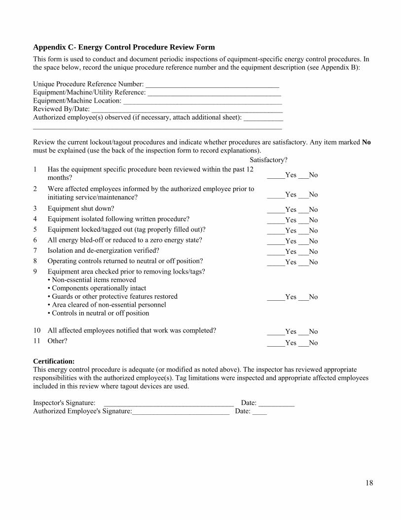
Appendix C- Energy Control Procedure Review Form
This form is used to conduct and document periodic inspections of equipment-specific energy control procedures. In the space below, record the unique procedure reference number and the equipment description (see Appendix B): Unique Procedure Reference Number: _____________________________________ Equipment/Machine/Utility Reference: _____________________________________ Equipment/Machine Location: ____________________________________________ Reviewed By/Date: _____________________________________________________ Authorized employee(s) observed (if necessary, attach additional sheet): ___________ _____________________________________________________________________ Review the current lockout/tagout procedures and indicate whether procedures are satisfactory. Any item marked No must be explained (use the back of the inspection form to record explanations). Satisfactory? 1 Has the equipment specific procedure been reviewed within the past 12
months? _____Yes ___No
2 Were affected employees informed by the authorized employee prior to initiating service/maintenance? _____Yes ___No
3 Equipment shut down? _____Yes ___No 4 Equipment isolated following written procedure? _____Yes ___No 5 Equipment locked/tagged out (tag properly filled out)? _____Yes ___No 6 All energy bled-off or reduced to a zero energy state? _____Yes ___No 7 Isolation and de-energization verified? _____Yes ___No 8 Operating controls returned to neutral or off position? _____Yes ___No 9 Equipment area checked prior to removing locks/tags?
• Non-essential items removed • Components operationally intact • Guards or other protective features restored • Area cleared of non-essential personnel • Controls in neutral or off position
_____Yes ___No
10 All affected employees notified that work was completed? _____Yes ___No 11 Other? _____Yes ___No Certification:
This energy control procedure is adequate (or modified as noted above). The inspector has reviewed appropriate responsibilities with the authorized employee(s). Tag limitations were inspected and appropriate affected employees included in this review where tagout devices are used. Inspector's Signature: ____________________________________ Date: __________ Authorized Employee's Signature:___________________________ Date: ____

19
Appendix – D Supervisory Lock and Tag Removal Form
1. Directions: All information below must be complete before lock is removed.
Was attempt made to contact Employee? Yes No
Employee Name: _________________________________________ Date: ______________ Clock Number: ______________________________________ Shift: __________________ Group/Zone/Shop: ___________________________________________________________ Specific Area of Lock and Tag: (Location and Equipment/Machine of lock and Tag) ______________________________________________________________________________ ______________________________________________________________________________
2. Are all employees clear of the Equipment or Machine? Yes No
Are all electrical/mechanical operations, equipment or processes now safe to operate? Yes No Did Supervisor inspect the area before removal of Lock/Tag? Yes No Did Supervisor inspect the area before restart of Equipment? Yes No Comments: ____________________________________________________________________
3. Signature(s) to be obtained before removal of Lock and Tag:
___________________________________ ______________________________________ Group/Zone/Shop Supervisor Superintendent ____________________________________ _______________________________________ Date Date

20
Appendix B- Energy Control Procedure Template
This checklist documents the specific lockout/tagout procedures to be followed when servicing/maintaining the equipment/machine/utility listed below. Unique Procedure Reference Number: ____LO/TO - 01___________________________ Equipment/Machine/Utility Reference: _Gas Fired Domestic Hot Water Heaters______ Equipment/Machine Location: __Campus Wide_________________________________ Prepared By/Date: ___Plumbing Foreman (11-17-2011)__________________________ Approved/Reviewed By/Date: ___Safety Manager (12-1-2011)___________________ Procedure Type (Check all that apply) Multi-point lockout and tagout X Multi-point tagout only Group lockout or tagout (Name, title, contact information of designated authorized employee: ___________Plumbing
Foreman____________________________________________) Coordination with outside contractor (Name, title, contact information of contractor:______N/A_______________________ ________________________________________________________________) Service/maintenance activities requiring use of this lockout/tagout procedure: Servicing and maintenance on Gas Water Heater
Summary of energy sources and lockout/tagout required In space below, list each energy source of concern, the magnitude of the energy, the means and location for lockout of the source, and the lockout device needed. Include special precautions needed to bleed, ground, or otherwise disengage energy sources. This information will be addressed in greater detail in the specific procedures on the next page. Attach equipment schematic or drawing depicting the information provided.
Hazardous energy
type/source
Magnitude Isolation point/device,
location, schematic reference
Special precautions for
bleeding, grounding,
disengaging, etc.
Required lockout/tagout
devices
Pressure City Water Shut off Valve Thermal Temp 180F Shut off Valve Other Natural Gas Unit gas shut off
21
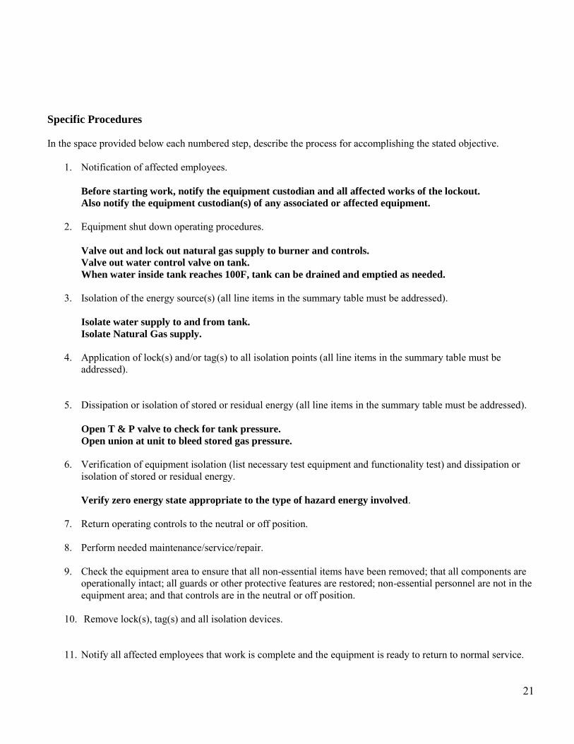
Specific Procedures In the space provided below each numbered step, describe the process for accomplishing the stated objective.
1. Notification of affected employees. Before starting work, notify the equipment custodian and all affected works of the lockout.
Also notify the equipment custodian(s) of any associated or affected equipment.
2. Equipment shut down operating procedures.
Valve out and lock out natural gas supply to burner and controls.
Valve out water control valve on tank.
When water inside tank reaches 100F, tank can be drained and emptied as needed.
3. Isolation of the energy source(s) (all line items in the summary table must be addressed).
Isolate water supply to and from tank.
Isolate Natural Gas supply.
4. Application of lock(s) and/or tag(s) to all isolation points (all line items in the summary table must be
addressed).
5. Dissipation or isolation of stored or residual energy (all line items in the summary table must be addressed).
Open T & P valve to check for tank pressure.
Open union at unit to bleed stored gas pressure.
6. Verification of equipment isolation (list necessary test equipment and functionality test) and dissipation or
isolation of stored or residual energy. Verify zero energy state appropriate to the type of hazard energy involved.
7. Return operating controls to the neutral or off position.
8. Perform needed maintenance/service/repair.
9. Check the equipment area to ensure that all non-essential items have been removed; that all components are
operationally intact; all guards or other protective features are restored; non-essential personnel are not in the equipment area; and that controls are in the neutral or off position.
10. Remove lock(s), tag(s) and all isolation devices.
11. Notify all affected employees that work is complete and the equipment is ready to return to normal service.

22
Appendix B- Energy Control Procedure Template
This checklist documents the specific lockout/tagout procedures to be followed when servicing/maintaining the equipment/machine/utility listed below. Unique Procedure Reference Number: ____LO/TO - 02___________________________ Equipment/Machine/Utility Reference: _Domestic Hot Water Return Pumps______ Equipment/Machine Location: __Campus Wide_________________________________ Prepared By/Date: ___Plumbing Foreman (11-17-2011)__________________________ Approved/Reviewed By/Date: ___Safety manager (12-1-2011)___________________ Procedure Type (Check all that apply) Multi-point lockout and tagout X Multi-point tagout only Group lockout or tagout (Name, title, contact information of designated authorized employee: __Plumbing Foreman
_______________________________________________________________) Coordination with outside contractor (Name, title, contact information of contractor:______N/A_______________________ ________________________________________________________________) Service/maintenance activities requiring use of this lockout/tagout procedure: Servicing or replacing the Sump Pump
Summary of energy sources and lockout/tagout required In space below, list each energy source of concern, the magnitude of the energy, the means and location for lockout of the source, and the lockout device needed. Include special precautions needed to bleed, ground, or otherwise disengage energy sources. This information will be addressed in greater detail in the specific procedures on the next page. Attach equipment schematic or drawing depicting the information provided.
Hazardous energy
type/source
Magnitude Isolation point/device,
location, schematic reference
Special precautions for
bleeding, grounding,
disengaging, etc.
Required lockout/tagout
devices
Electrical 110v Power panel Pressure Supply Valve

23
Specific Procedures In the space provided below each numbered step, describe the process for accomplishing the stated objective.
1. Notification of affected employees. Before starting work, notify the equipment custodian and all affected works of the lockout.
Also notify the equipment custodian(s) of any associated or affected equipment.
2. Equipment shut down operating procedures.
Turn off and Lock out Tag out electrical power supply at disconnect and or breaker panel.
Close isolation valves on water supply and return to pump.
3. Isolation of the energy source(s) (all line items in the summary table must be addressed).
Isolate electrical power source at disconnect and or breaker box.
Isolate water supply to and from pump.
4. Application of lock(s) and/or tag(s) to all isolation points (all line items in the summary table must be
addressed). Lock out / Tag out breaker and or disconnect box.
Lock out / Tag out valve drain water from piping valve out water supply to pump.
5. Dissipation or isolation of stored or residual energy (all line items in the summary table must be addressed).
Check for voltage with voltage tester.
6. Verification of equipment isolation (list necessary test equipment and functionality test) and dissipation or
isolation of stored or residual energy. Verify zero energy state appropriate to the type of hazard energy involved.
7. Return operating controls to the neutral or off position.
8. Perform needed maintenance/service/repair.
9. Check the equipment area to ensure that all non-essential items have been removed; that all components are
operationally intact; all guards or other protective features are restored; non-essential personnel are not in the equipment area; and that controls are in the neutral or off position.
10. Remove lock(s), tag(s) and all isolation devices.
11. Notify all affected employees that work is complete and the equipment is ready to return to normal service.

24
Appendix B- Energy Control Procedure Template
This checklist documents the specific lockout/tagout procedures to be followed when servicing/maintaining the equipment/machine/utility listed below. Unique Procedure Reference Number: ____LO/TO - 03___________________________ Equipment/Machine/Utility Reference: _Sump Pumps Sewage Lift Station Pumps______ Equipment/Machine Location: __Campus Wide_________________________________ Prepared By/Date: ___Plumbing Foreman (11-17-2011)______________________________ Approved/Reviewed By/Date: ___Safety Manager (12-1-2011)___________________ Procedure Type (Check all that apply) Multi-point lockout and tagout X
Multi-point tagout only Group lockout or tagout (Name, title, contact information of designated authorized employee: __Plumbing Foreman ________________________________________________________________) Coordination with outside contractor (Name, title, contact information of contractor:______N/A_______________________ ________________________________________________________________) Service/maintenance activities requiring use of this lockout/tagout procedure: Servicing or replacing the Sump Pump
Summary of energy sources and lockout/tagout required In space below, list each energy source of concern, the magnitude of the energy, the means and location for lockout of the source, and the lockout device needed. Include special precautions needed to bleed, ground, or otherwise disengage energy sources. This information will be addressed in greater detail in the specific procedures on the next page. Attach equipment schematic or drawing depicting the information provided.
Hazardous energy
type/source
Magnitude Isolation point/device,
location, schematic reference
Special precautions for
bleeding, grounding,
disengaging, etc.
Required lockout/tagout
devices
Electrical 110V Power Panel Pressure Supply Valve Mechanical

25
Specific Procedures In the space provided below each numbered step, describe the process for accomplishing the stated objective.
1. Notification of affected employees. Before starting work, notify the equipment custodian and all affected works of the lockout.
Also notify the equipment custodian(s) of any associated or affected equipment.
2. Equipment shut down operating procedures.
Lock out Tag out electrical power supply at disconnect and or breaker panel.
Lock out and Tag out and close valves from pump.
3. Isolation of the energy source(s) (all line items in the summary table must be addressed).
Isolate electrical power source at disconnect and or breaker box.
Discharge valve from pump and water that discharges into pump basin.
4. Application of lock(s) and/or tag(s) to all isolation points (all line items in the summary table must be
addressed). Lock out / Tag out breaker and or disconnect box.
Lock out / Tag out valve drain water from piping valve out water supply that discharges to pump
basin.
5. Dissipation or isolation of stored or residual energy (all line items in the summary table must be addressed).
Check for voltage with voltage tester.
Drain water from both piping and basin systems.
6. Verification of equipment isolation (list necessary test equipment and functionality test) and dissipation or
isolation of stored or residual energy. Verify zero energy state appropriate to the type of hazard energy involved.
7. Return operating controls to the neutral or off position.
8. Perform needed maintenance/service/repair.
9. Check the equipment area to ensure that all non-essential items have been removed; that all components are
operationally intact; all guards or other protective features are restored; non-essential personnel are not in the equipment area; and that controls are in the neutral or off position.
10. Remove lock(s), tag(s) and all isolation devices.
11. Notify all affected employees that work is complete and the equipment is ready to return to normal service.

26
Appendix B- Energy Control Procedure Template
This checklist documents the specific lockout/tagout procedures to be followed when servicing/maintaining the equipment/machine/utility listed below. Unique Procedure Reference Number: ____LO/TO-04___________________________ Equipment/Machine/Utility Reference: _____Auto Claves________________________ Equipment/Machine Location: ________Mechanical Rooms______________________ Prepared By/Date: ___________HVAC Foreman______11/18/2011_____________________ Approved/Reviewed By/Date: _____Safety Manager___12/01/2011________________ Procedure Type (Check all that apply) Multi-point lockout and tagout (X)
Multi-point tagout only Group lockout or tagout (Name, title, contact information of designated authorized employee: ______________ _____HVAC Employees___________________________________________________________) Coordination with outside contractor (Name, title, contact information of contractor:________________________________ ____________N/A____________________________________________________) Service/maintenance activities requiring use of this lockout/tagout procedure:
Servicing or preforming maintenance on an Auto Clave
Summary of energy sources and lockout/tagout required In space below, list each energy source of concern, the magnitude of the energy, the means and location for lockout of the source, and the lockout device needed. Include special precautions needed to bleed, ground, or otherwise disengage energy sources. This information will be addressed in greater detail in the specific procedures on the next page. Attach equipment schematic or drawing depicting the information provided.
Hazardous energy
type/source
Magnitude Isolation point/device,
location, schematic reference
Special precautions for bleeding, grounding,
disengaging, etc.
Required lockout/tagout
devices
Electrical 115/208/230/460 Disconnect/VFD Control Panel
Power Panel
Pressure Air/Water Valve out & Bleed Pressure
Supply Valve
Thermal Heat/Steam Valve Out and Let cool
Supply Valve
27
Specific Procedures In the space provided below each numbered step, describe the process for accomplishing the stated objective.
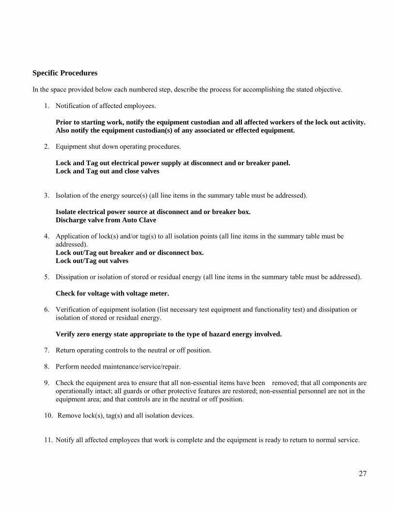
1. Notification of affected employees. Prior to starting work, notify the equipment custodian and all affected workers of the lock out activity.
Also notify the equipment custodian(s) of any associated or effected equipment.
2. Equipment shut down operating procedures.
Lock and Tag out electrical power supply at disconnect and or breaker panel.
Lock and Tag out and close valves
3. Isolation of the energy source(s) (all line items in the summary table must be addressed).
Isolate electrical power source at disconnect and or breaker box.
Discharge valve from Auto Clave
4. Application of lock(s) and/or tag(s) to all isolation points (all line items in the summary table must be
addressed). Lock out/Tag out breaker and or disconnect box.
Lock out/Tag out valves
5. Dissipation or isolation of stored or residual energy (all line items in the summary table must be addressed).
Check for voltage with voltage meter.
6. Verification of equipment isolation (list necessary test equipment and functionality test) and dissipation or
isolation of stored or residual energy.
Verify zero energy state appropriate to the type of hazard energy involved.
7. Return operating controls to the neutral or off position.
8. Perform needed maintenance/service/repair.
9. Check the equipment area to ensure that all non-essential items have been removed; that all components are
operationally intact; all guards or other protective features are restored; non-essential personnel are not in the equipment area; and that controls are in the neutral or off position.
10. Remove lock(s), tag(s) and all isolation devices.
11. Notify all affected employees that work is complete and the equipment is ready to return to normal service.

28

29

30
31
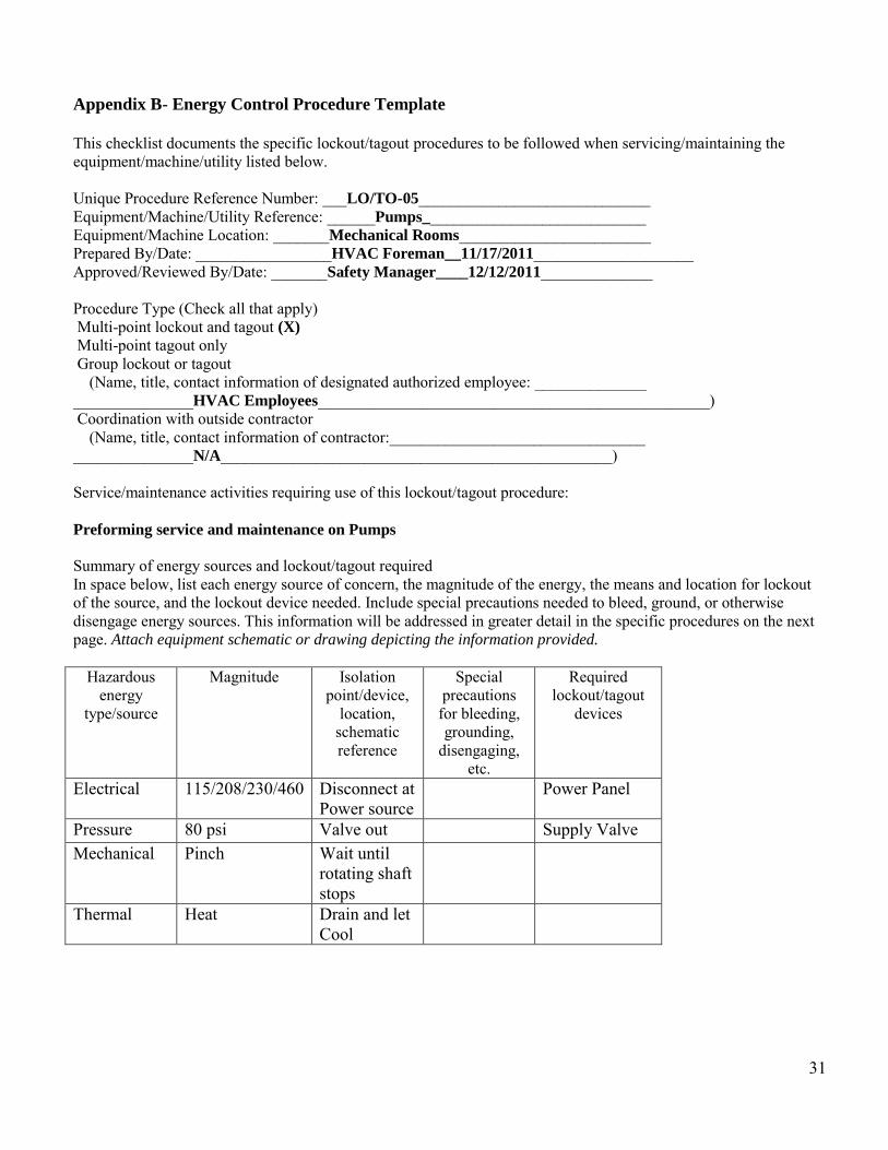
Appendix B- Energy Control Procedure Template
This checklist documents the specific lockout/tagout procedures to be followed when servicing/maintaining the equipment/machine/utility listed below. Unique Procedure Reference Number: ___LO/TO-05_____________________________ Equipment/Machine/Utility Reference: ______Pumps____________________________ Equipment/Machine Location: _______Mechanical Rooms________________________ Prepared By/Date: _________________HVAC Foreman__11/17/2011____________________ Approved/Reviewed By/Date: _______Safety Manager____12/12/2011______________ Procedure Type (Check all that apply) Multi-point lockout and tagout (X) Multi-point tagout only Group lockout or tagout (Name, title, contact information of designated authorized employee: ______________ _______________HVAC Employees_________________________________________________) Coordination with outside contractor (Name, title, contact information of contractor:________________________________ _______________N/A_________________________________________________) Service/maintenance activities requiring use of this lockout/tagout procedure: Preforming service and maintenance on Pumps
Summary of energy sources and lockout/tagout required In space below, list each energy source of concern, the magnitude of the energy, the means and location for lockout of the source, and the lockout device needed. Include special precautions needed to bleed, ground, or otherwise disengage energy sources. This information will be addressed in greater detail in the specific procedures on the next page. Attach equipment schematic or drawing depicting the information provided.
Hazardous energy
type/source
Magnitude Isolation point/device,
location, schematic reference
Special precautions
for bleeding, grounding,
disengaging, etc.
Required lockout/tagout
devices
Electrical 115/208/230/460 Disconnect at Power source
Power Panel
Pressure 80 psi Valve out Supply Valve Mechanical Pinch Wait until
rotating shaft stops
Thermal Heat Drain and let Cool

32
Specific Procedures In the space provided below each numbered step, describe the process for accomplishing the stated objective.
1. Notification of affected employees.
Before starting work, notify the equipment custodian and all affected works of the lockout.
Also notify the equipment custodian(s) of any associated or affected equipment.
2. Equipment shut down operating procedures.
Lock out Tag out electrical power supply at disconnect and or breaker panel.
Close inlet valves to pump – Lock out and Tag out valves
3. Isolation of the energy source(s) (all line items in the summary table must be addressed).
Isolate electrical power source at disconnect and or breaker panel.
Discharge valves from pump.
4. Application of lock(s) and/or tag(s) to all isolation points (all line items in the summary table must be
addressed). Lock out and Tag out breaker and or disconnect box.
Lock out and Tag out valves water or steam supply.
5. Dissipation or isolation of stored or residual energy (all line items in the summary table must be addressed).
Check for voltage with voltage tester.
Drain water from piping.
6. Verification of equipment isolation (list necessary test equipment and functionality test) and dissipation or
isolation of stored or residual energy.
Verify zero energy state appropriate to the type of hazard energy involved.
7. Return operating controls to the neutral or off position.
8. Perform needed maintenance/service/repair.
9. Check the equipment area to ensure that all non-essential items have been removed; that all components are
operationally intact; all guards or other protective features are restored; non-essential personnel are not in the equipment area; and that controls are in the neutral or off position.
10. Remove lock(s), tag(s) and all isolation devices.
11. Notify all affected employees that work is complete and the equipment is ready to return to normal service.

33

34

35
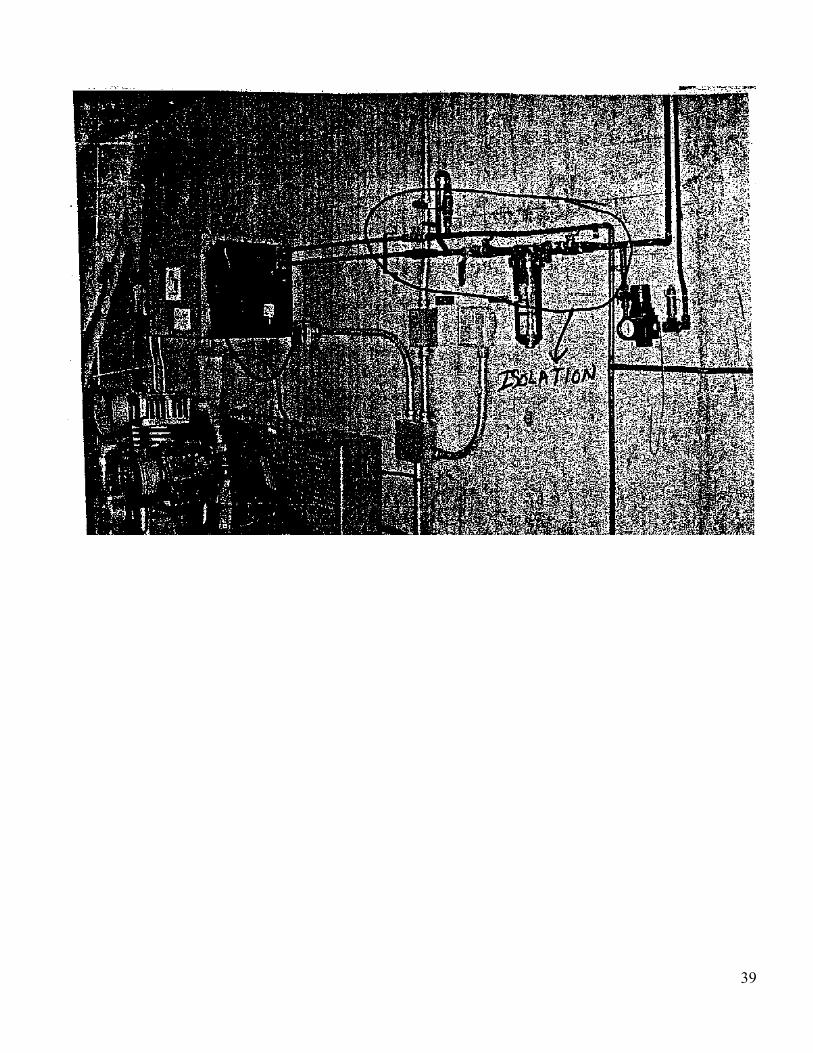
Appendix B- Energy Control Procedure Template This checklist documents the specific lockout/tagout procedures to be followed when servicing/maintaining the equipment/machine/utility listed below. Unique Procedure Reference Number: _____LO/TO - 06_________________________ Equipment/Machine/Utility Reference: ______Air Compressors____________________ Equipment/Machine Location: __________Mechanical Rooms Campus Wide_________ Prepared By/Date: ______________HVAC Foreman___11/17/2011________________ Approved/Reviewed By/Date: _____Safety Manager___12/12/2011__________________ Procedure Type (Check all that apply) Multi-point lockout and tagout X Multi-point tagout only Group lockout or tagout (Name, title, contact information of designated authorized employee: ______________ __________________HVAC Employees______________________________________________) Coordination with outside contractor (Name, title, contact information of contractor:________________________________ _______________________N/A_________________________________________) Service/maintenance activities requiring use of this lockout/tagout procedure:
Preforming service and maintenance on Pumps
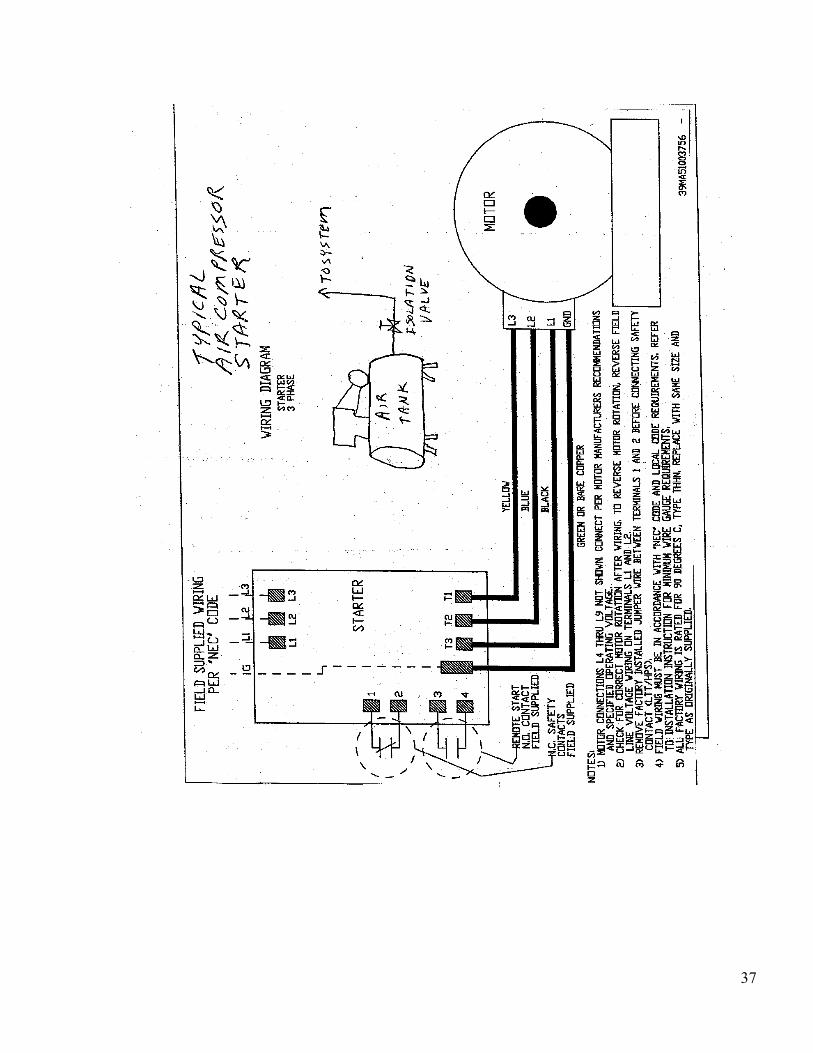
Summary of energy sources and lockout/tagout required In space below, list each energy source of concern, the magnitude of the energy, the means and location for lockout of the source, and the lockout device needed. Include special precautions needed to bleed, ground, or otherwise disengage energy sources. This information will be addressed in greater detail in the specific procedures on the next page. Attach equipment schematic or drawing depicting the information provided.
Hazardous energy
type/source
Magnitude Isolation point/device, location, schematic
reference
Special precautions
for bleeding,
grounding, disengaging,
etc.
Required lockout/tagout
devices
Electrical 110/208/230/460 Disconnect Power Panel Pressure Air Pressure Supply
Valve Mechanical Pinch Danger Belts/Pullys/Flywheel Thermal Heat Let Heads
Cool
36
Specific Procedures In the space provided below each numbered step, describe the process for accomplishing the stated objective.
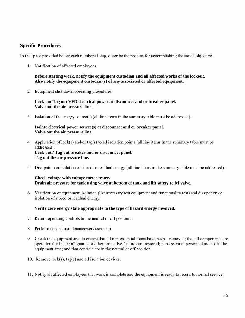
1. Notification of affected employees.
Before starting work, notify the equipment custodian and all affected works of the lockout.
Also notify the equipment custodian(s) of any associated or affected equipment.
2. Equipment shut down operating procedures.
Lock out Tag out VFD electrical power at disconnect and or breaker panel.
Valve out the air pressure line.
3. Isolation of the energy source(s) (all line items in the summary table must be addressed).
Isolate electrical power source(s) at disconnect and or breaker panel.
Valve out the air pressure line.
4. Application of lock(s) and/or tag(s) to all isolation points (all line items in the summary table must be
addressed). Lock out / Tag out breaker and or disconnect panel.
Tag out the air pressure line.
5. Dissipation or isolation of stored or residual energy (all line items in the summary table must be addressed).
Check voltage with voltage meter tester.
Drain air pressure for tank using valve at bottom of tank and lift safety relief valve.
6. Verification of equipment isolation (list necessary test equipment and functionality test) and dissipation or
isolation of stored or residual energy. Verify zero energy state appropriate to the type of hazard energy involved.
7. Return operating controls to the neutral or off position.
8. Perform needed maintenance/service/repair.
9. Check the equipment area to ensure that all non-essential items have been removed; that all components are
operationally intact; all guards or other protective features are restored; non-essential personnel are not in the equipment area; and that controls are in the neutral or off position.
10. Remove lock(s), tag(s) and all isolation devices.
11. Notify all affected employees that work is complete and the equipment is ready to return to normal service.
37

38
39

40
Appendix B- Energy Control Procedure Template
This checklist documents the specific lockout/tagout procedures to be followed when servicing/maintaining the equipment/machine/utility listed below. Unique Procedure Reference Number: _____LO/TO - 07__________________________ Equipment/Machine/Utility Reference: _______Multi-Fan Air Handler Units (AHUs)___ Equipment/Machine Location: ______Campus Wide Mechanical Rooms_____________ Prepared By/Date: ______________HVAC Foreman___11/17/2011________________ Approved/Reviewed By/Date: ______Safety Manager___12/12/2011_______________ Procedure Type (Check all that apply) Multi-point lockout and tagout X
(Name, title, contact information of designated authorized employee: ______________ _______________HVAC Employees________________________________________) Coordination with outside contractor (Name, title, contact information of contractor:_______N/A_________________________ ________________________________________________________________) Service/maintenance activities requiring use of this lockout/tagout procedure: Preforming service and maintenance on Air Handler Units
Summary of energy sources and lockout/tagout required; In space below, list each energy source of concern, the magnitude of the energy, the means and location for lockout of the source, and the lockout device needed. Include special precautions needed to bleed, ground, or otherwise disengage energy sources. This information will be addressed in greater detail in the specific procedures on the next page. Attach equipment schematic or drawing depicting the information provided.
Hazardous energy
type/source
Magnitude Isolation point/device,
location, schematic reference
Special precautions for
bleeding, grounding,
disengaging, etc.
Required lockout/tagout
devices
Electrical 115/208/460 VFD/Starter Power Panel Mechanical Pinch Danger Belts, Pulles,
Blower Wheels
Power to supply and return fans

41
Specific Procedures In the space provided below each numbered step, describe the process for accomplishing the stated objective.
1. Notification of affected employees. Before starting work, notify the equipment custodian and all affected works of the lockout.
Also notify the equipment custodian(s) of any associated or affected equipment.
2. Equipment shut down operating procedures.
Lock out Tag out electrical power supply at VFD disconnect and or breaker panel.
Lock out and Tag out both supply and return fans.
3. Isolation of the energy source(s) (all line items in the summary table must be addressed).
Isolate electrical power supply at VFD disconnect and or breaker panel.
Isolate out both supply and return fans.
4. Application of lock(s) and/or tag(s) to all isolation points (all line items in the summary table must be
addressed). Lock out Tag out electrical power supply at VFD disconnect and or breaker panel.
Lock out and Tag out both supply and return fans.
5. Dissipation or isolation of stored or residual energy (all line items in the summary table must be addressed).
Check voltage with voltage meter tester.
6. Verification of equipment isolation (list necessary test equipment and functionality test) and dissipation or
isolation of stored or residual energy.
Verify zero energy state appropriate to the type of hazard energy involved.
7. Return operating controls to the neutral or off position.
8. Perform needed maintenance/service/repair.
9. Check the equipment area to ensure that all non-essential items have been removed; that all components are operationally intact; all guards or other protective features are restored; non-essential personnel are not in the equipment area; and that controls are in the neutral or off position.
10. Remove lock(s), tag(s) and all isolation devices.
11. Notify all affected employees that work is complete and the equipment is ready to return to normal service.

42

43

44
Appendix B- Energy Control Procedure Template
This checklist documents the specific lockout/tagout procedures to be followed when servicing/maintaining the equipment/machine/utility listed below. Unique Procedure Reference Number: ____LO/TO - 08___________________________ Equipment/Machine/Utility Reference: _______Boilers___________________________ Equipment/Machine Location: ________Mechanical Rooms Campus Wide__________ Prepared By/Date: _______________HVAC Foreman__11/17/2011_________________ Approved/Reviewed By/Date: _______Safety Manager___12/12/2011_______________ Procedure Type (Check all that apply) Multi-point lockout and tagout X Multi-point tagout only Group lockout or tagout (Name, title, contact information of designated authorized employee: ______________ ________________HVAC Employees________________________________________________) Coordination with outside contractor (Name, title, contact information of contractor:__________N/A______________________ ________________________________________________________________) Service/maintenance activities requiring use of this lockout/tagout procedure:
Preforming service and maintenance on Boilers
Summary of energy sources and lockout/tagout required : In space below, list each energy source of concern, the magnitude of the energy, the means and location for lockout of the source, and the lockout device needed. Include special precautions needed to bleed, ground, or otherwise disengage energy sources. This information will be addressed in greater detail in the specific procedures on the next page. Attach equipment schematic or drawing depicting the information provided.
Hazardous energy
type/source
Magnitude Isolation point/device,
location, schematic reference
Special precautions for
bleeding, grounding,
disengaging, etc.
Required lockout/tagout
devices
Electrical 115/230/460 Control Panel Power Panel Mechanical Pinch Danger Blower
Wheel
Thermal 160 degs Shutoff Valve Supply Valve Natural Gas Fumes/Fire Shutoff Valve Supply Valve

45
Specific Procedures In the space provided below each numbered step, describe the process for accomplishing the stated objective.
1. Notification of affected employees. Before starting work, notify the equipment custodian and all affected works of the lockout.
Also notify the equipment custodian(s) of any associated or affected equipment.
2. Equipment shut down operating procedures.
Lock out Tag out electrical power supply at disconnect and or breaker panel.
Lock out and Tag out supply lines.
3. Isolation of the energy source(s) (all line items in the summary table must be addressed).
Isolate electrical power source(s) at disconnect and or breaker panel.
Valve out the air pressure line.
4. Application of lock(s) and/or tag(s) to all isolation points (all line items in the summary table must be
addressed).
5. Dissipation or isolation of stored or residual energy (all line items in the summary table must be addressed).
Check voltage with voltage meter tester.
6. Verification of equipment isolation (list necessary test equipment and functionality test) and dissipation or
isolation of stored or residual energy. Verify zero energy state appropriate to the type of hazard energy involved.
7. Return operating controls to the neutral or off position.
8. Perform needed maintenance/service/repair.
9. Check the equipment area to ensure that all non-essential items have been removed; that all components are
operationally intact; all guards or other protective features are restored; non-essential personnel are not in the equipment area; and that controls are in the neutral or off position.
10. Remove lock(s), tag(s) and all isolation devices.
11. Notify all affected employees that work is complete and the equipment is ready to return to normal service.

46

47