University of Huddersfield Repositoryeprints.hud.ac.uk/29753/1/reseasch gate.pdf · Additionally,...
23
University of Huddersfield Repository Hamza, Esam A review of using computational fluid dynamic in simulating of friction stir welding and parametric studies Original Citation Hamza, Esam (2016) A review of using computational fluid dynamic in simulating of friction stir welding and parametric studies. In: 11th International Symposium on FSW (11ISFSW), 17-19 May 2016, TWI Ltd, Cambridge, UK. (Unpublished) This version is available at http://eprints.hud.ac.uk/id/eprint/29753/ The University Repository is a digital collection of the research output of the University, available on Open Access. Copyright and Moral Rights for the items on this site are retained by the individual author and/or other copyright owners. Users may access full items free of charge; copies of full text items generally can be reproduced, displayed or performed and given to third parties in any format or medium for personal research or study, educational or not-for-profit purposes without prior permission or charge, provided: • The authors, title and full bibliographic details is credited in any copy; • A hyperlink and/or URL is included for the original metadata page; and • The content is not changed in any way. For more information, including our policy and submission procedure, please contact the Repository Team at: [email protected]. http://eprints.hud.ac.uk/
Transcript of University of Huddersfield Repositoryeprints.hud.ac.uk/29753/1/reseasch gate.pdf · Additionally,...
University of Huddersfield Repository
Hamza, Esam
A review of using computational fluid dynamic in simulating of friction stir welding and parametric studies
Original Citation
Hamza, Esam (2016) A review of using computational fluid dynamic in simulating of friction stir welding and parametric studies. In: 11th International Symposium on FSW (11ISFSW), 1719 May 2016, TWI Ltd, Cambridge, UK. (Unpublished)
This version is available at http://eprints.hud.ac.uk/id/eprint/29753/
The University Repository is a digital collection of the research output of theUniversity, available on Open Access. Copyright and Moral Rights for the itemson this site are retained by the individual author and/or other copyright owners.Users may access full items free of charge; copies of full text items generallycan be reproduced, displayed or performed and given to third parties in anyformat or medium for personal research or study, educational or notforprofitpurposes without prior permission or charge, provided:
• The authors, title and full bibliographic details is credited in any copy;• A hyperlink and/or URL is included for the original metadata page; and• The content is not changed in any way.
For more information, including our policy and submission procedure, pleasecontact the Repository Team at: [email protected].
http://eprints.hud.ac.uk/
11th International Symposium on FSW (11ISFSW) 17-19 May 2016 at TWI Ltd, Cambridge, UK
1
A review of using Computational Fluid Dynamic in simulating of Friction Stir Welding
and Parametric studies
E.M. Hamza
School of computing and Engineering, University of Huddersfield, Queensgate, Huddersfield
HD1 3HD, UK
Abstract
Friction Stir Welding (FSW) is still gradually evolving where it is newer than most
thermomechanical processes and due to its ability to avoid many of the common defects in
other welding techniques it has become largely used, particularly for those materials that are
soft.[1]
Since the invention of friction stir welding by The Welding Institute (TWI), Cambridge, UK,
there have been many attempts to comprehend the physical phenomena that take place
during this process. These phenomena can be affected by the welding variables and
determine the quality of the welded joint as well. Numerous studies have been carried out
based on the experimental approach. However, the experiments were often time-consuming
and costly. As an alternative and to overcome these problems that accompany the
experimental works, other approaches have been used such as numerical and analytical
modeling. Numerical modeling was represented in two main methods, which are fluid
dynamic (simulation of material flow and temperature distribution) and solid mechanics
(simulation of temperature distribution, stress and strain).[2]
This paper focuses on applying Computational Fluid Dynamic (CFD) in modelling of FSW as
its one of the most powerful numerical analysis technique. Whereas FSW is a complex
process, the so important coupled physical phenomena such as heat generation, heat
transfer, and metal flow are discussed. In addition, the latest developments in analysis of
FSW using CFD are reviewed. Although, this technique is promising, there are still important
issues need to be addressed. Thus, some factors that affect the reliability and applicability of
CFD modelling are highlighted, and some future opportunities are identified.

11th International Symposium on FSW (11ISFSW) 17-19 May 2016 at TWI Ltd, Cambridge, UK
2
1. Introduction
Friction Stir Welding is like any other welding process where careful choice of process
parameters is vital for the attainment of welds without any defect and good micro-structural
and mechanical characteristics. Parameters such as rotational speed, translational speed,
and the tool geometry determine the amount of energy input to the weld and the rate of heat
generation at the interface between the tool and the workpiece. Peak joint temperature and
temperature profile in the region near the joint can have a significant impact on the plastic
deformation zone, heat affected zones, and joint properties. Additionally, cooling rates are
closely related to the joint temperature profiles and directly influence the final microstructure
and residual stress state developed in the join which in role affect the global feature of the
weld joint.[3-5].
Negative effects from the thermal cycle of welding might take place in the heat affected zone
and the zone of plastic deformation. Thus, the information about temperature distribution is
of great significance in estimating numerous thermal aspects that results in controlling the
process and acquiring sound weld by avoiding the imperfection sources. The aspects of
welding thermal cycles are distinguished in heat flux generated, rate of heating, peak
temperature, time at temperature, temperature distributions, cooling endpoints and cooling
rates of heated zones. Knowing the above aspects in detail, a lot can be done to explain
how welding affects properties and microstructure of the given material.[6] However, when it
comes to virtual measurements of temperature distribution in the stirring zone, there are
difficulties because of the severe plastic deformation occurring when the tool is moving.[7]
Despite the complication of material flow in FSW, it is important to understand the nature of
flow that aid in optimal tool design and to accomplish a sound weld. Material flow also relies
mainly on process parameters (tool rotation rate and direction, that are anticlockwise or
clockwise, travel speed, plunge depth, spindle angle), the tool geometry (pin and shoulder
design, relative dimension of pin and shoulder), the characteristics of the material to be
welded, and work piece temperature. Due to the thermomechanical interrelation, it is not the
nature of deformation alone that affects the flow, but it is also strongly linked to the thermal
cycle of FSW where they together determine the nature of metal flow.[2, 8] As a flow or
geometric, the defects in FSW have been classified where lack of penetration takes place as
a result of inadequate pin penetration depth or incorrect seam tracking is a major defect
connected with the geometry while the nugget collapse or lack of consolidation, flash
formation, lack of fill, surface galling and wormholes are all related to flow which are hardly
unavoidable. Accordingly, it is useful having a means to understand and estimate the effects
of friction stir welding parameters that leads to visualize the process and define the quality of
11th International Symposium on FSW (11ISFSW) 17-19 May 2016 at TWI Ltd, Cambridge, UK
3
the weld.[3-5] Although the experimental work is a most common reliable approach in
conducting the investigation studies, the obstacles of acquiring data from the weld zone still
a question. Therefore, the necessity is to improve reliable alternatives.
2. Heat generation in Friction Stir Welding
The losses in the process of Friction Stir Welding resulting from the effects of microstructure
are represented in the difference between the power input and the value of the generated
heat which is profitable in the welding process.[9] Friction between the workpiece and the
tool is one of the main sources of heat generation in the friction stir welding process. From
an analytical point of view, the total heat generation Qtotal that is basically resulting by
friction can be distinguished in the generated heat amount under the tool shoulder Q1 and
the generated heat amount around the tool pin Q2 in addition to the generated heat amount
under the tool pin Q3. [10] It is worth mentioning here that the tool shoulder plays a major
role in generation of heat when dealing with low thickness workpieces while in the case of
high thickness workpieces the tool probe shows more activities. Besides, the pressure under
the shoulder is boosted either by value of the applied force or the shoulder form which both
affect the heat generation.[2] Localised plastic deformation is the other main source to heat
generation, which occurs in the tool faying layers of workpiece. Energy of deformation is
divided into two parts; the first is stored in the material microstructure, and however, the
other is transformed to heat. In spite of that, there are no experimental measurements for
these two parts, but according to the numerical modeling, the values of the acquired heat
from this plastic deformation fluctuate from 2% to 20%.[10]
It is a vital importance to know that the translational speed is much less than the peripheral
speed of each of the shoulder and the pin, as well as the high shear stresses at the interface
between the tool and the workpiece drive the viscous dissipation in the workpiece.
Therefore, the behaviour of the contact interface is needed to be represented if we are
modeling of heat generation in the presence of viscous dissipation. Actually, the contact
condition at the interface can be different; whereas the material can slip or sticks to the tool.
Sticking implies that the material moves at the velocity of the tool whereas slipping means
the tool velocity may be higher than the material velocity. In this context, there is a model
simulates the heat generation in friction stir welding was developed by Schmidt et al[9]. The
model was by considering the shear forces between the contact surfaces; they described
three diverse states of contact which are sticking condition, sliding condition and the partial
sliding/sticking condition.
11th International Symposium on FSW (11ISFSW) 17-19 May 2016 at TWI Ltd, Cambridge, UK
4
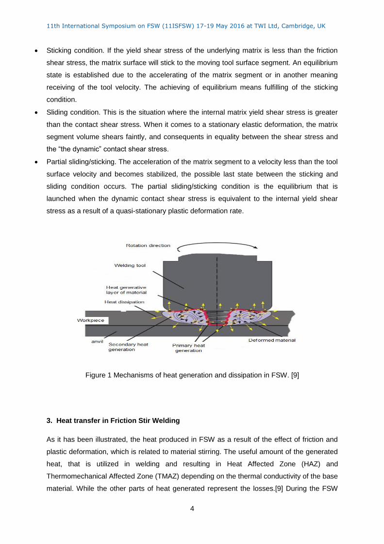
Sticking condition. If the yield shear stress of the underlying matrix is less than the friction
shear stress, the matrix surface will stick to the moving tool surface segment. An equilibrium
state is established due to the accelerating of the matrix segment or in another meaning
receiving of the tool velocity. The achieving of equilibrium means fulfilling of the sticking
condition.
Sliding condition. This is the situation where the internal matrix yield shear stress is greater
than the contact shear stress. When it comes to a stationary elastic deformation, the matrix
segment volume shears faintly, and consequents in equality between the shear stress and
the “the dynamic” contact shear stress.
Partial sliding/sticking. The acceleration of the matrix segment to a velocity less than the tool
surface velocity and becomes stabilized, the possible last state between the sticking and
sliding condition occurs. The partial sliding/sticking condition is the equilibrium that is
launched when the dynamic contact shear stress is equivalent to the internal yield shear
stress as a result of a quasi-stationary plastic deformation rate.
Figure 1 Mechanisms of heat generation and dissipation in FSW. [9]
3. Heat transfer in Friction Stir Welding
As it has been illustrated, the heat produced in FSW as a result of the effect of friction and
plastic deformation, which is related to material stirring. The useful amount of the generated
heat, that is utilized in welding and resulting in Heat Affected Zone (HAZ) and
Thermomechanical Affected Zone (TMAZ) depending on the thermal conductivity of the base
material. While the other parts of heat generated represent the losses.[9] During the FSW
11th International Symposium on FSW (11ISFSW) 17-19 May 2016 at TWI Ltd, Cambridge, UK
5
process, the heat is lost through conduction and radiation, along with convection, which
plays a role by changing the gradient in the temperature of air adjacent to the metal. Usually
to produce a model characterized by accuracy, it is significant to rush out into define and
consider the most important sources of heat loss. The main part of the heat losses is
represented in the heat that dissipates through the tool and backing plate while the minor
part can be found at the clamping metal and workpiece surfaces.[11]Compared to the heat
input, the heat lost to the tool is a small portion which can be computed by measuring the
temperature at two points along the tool axis and applying a simple heat flow model. Many
writers have concluded that the percentage of heat losses is about 5%, after experimental
assessments of the temperature distribution models. Heat loss from the workpiece top
surface can be estimated by taking into account the convection and radiation heat transfer
involved in the following equation.[2]
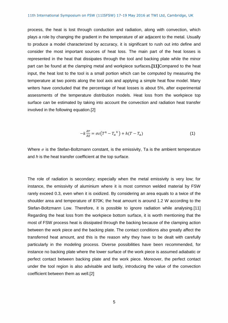
−𝑘𝜕𝑇
𝜕𝑍= 𝜎휀(𝑇4 − 𝑇𝑎
4 ) + ℎ(𝑇 − 𝑇𝑎) (1)
Where 𝜎 is the Stefan-Boltzmann constant, is the emissivity, Ta is the ambient temperature
and h is the heat transfer coefficient at the top surface.
The role of radiation is secondary; especially when the metal emissivity is very low; for
instance, the emissivity of aluminium where it is most common welded material by FSW
rarely exceed 0.3, even when it is oxidized. By considering an area equals to a twice of the
shoulder area and temperature of 870K; the heat amount is around 1.2 W according to the
Stefan-Boltzmann Low. Therefore, it is possible to ignore radiation while analysing.[11]
Regarding the heat loss from the workpiece bottom surface, it is worth mentioning that the
most of FSW process heat is dissipated through the backing because of the clamping action
between the work piece and the backing plate. The contact conditions also greatly affect the
transferred heat amount, and this is the reason why they have to be dealt with carefully
particularly in the modeling process. Diverse possibilities have been recommended, for
instance no backing plate where the lower surface of the work piece is assumed adiabatic or
perfect contact between backing plate and the work piece. Moreover, the perfect contact
under the tool region is also advisable and lastly, introducing the value of the convection
coefficient between them as well.[2]
11th International Symposium on FSW (11ISFSW) 17-19 May 2016 at TWI Ltd, Cambridge, UK
6
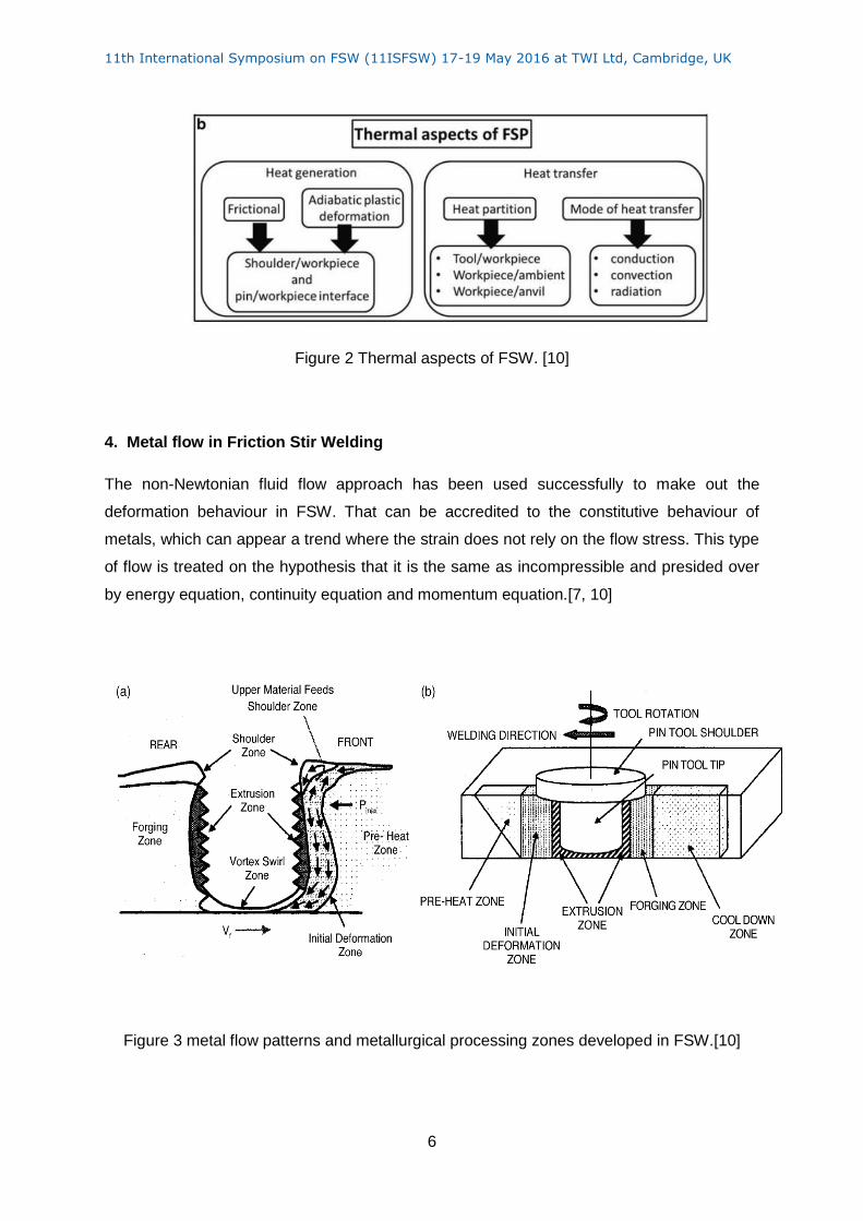
Figure 2 Thermal aspects of FSW. [10]
4. Metal flow in Friction Stir Welding
The non-Newtonian fluid flow approach has been used successfully to make out the
deformation behaviour in FSW. That can be accredited to the constitutive behaviour of
metals, which can appear a trend where the strain does not rely on the flow stress. This type
of flow is treated on the hypothesis that it is the same as incompressible and presided over
by energy equation, continuity equation and momentum equation.[7, 10]
Figure 3 metal flow patterns and metallurgical processing zones developed in FSW.[10]

11th International Symposium on FSW (11ISFSW) 17-19 May 2016 at TWI Ltd, Cambridge, UK
7
Many experiments have been performed to mark out the deformation and to understand the
flow behaviour by using marker materials implanted into the workpiece. The majority of these
experiments have, however, depicted two types of deformations. The first one occurs at the
interface between the work piece and the tool shoulder, whereas the second is at the
interface between work piece and the tool pin. As presented in the figure 4,a,b the marker
material indicates how the material deforms in the retreating and advancing sides at the
shoulder and work piece interface. The marker is transferred from advancing side to the
retreating side by the tool and vice versa, even so; the dissimilarity is that the direction of
advancing side material movement is vertically downwards into the work piece while the
movement of retreating side material is vertically up pushed to the work piece surface. Some
of the material may also be pushed out as a flash depending on the welding conditions.[10]
In the figure 4, c and d shows the movement of marker material caused by the deformation
at the tool pin and the work piece interface. At the advancing side, the marker material is
moved close to its initial position. The marker material at the retreating is pushed, which is
the same as the case of work piece interface and the tool shoulder. Concerning the
deformation at the tool pin bottom and for some extent, it is same as deformation at the
shoulder where the dissimilarity is accredited to the anvil constraint. [10]
Figure 4 the material transport in the shoulder/workpiece interface region and in the tool
pin/workpiece interface region interface. [10]
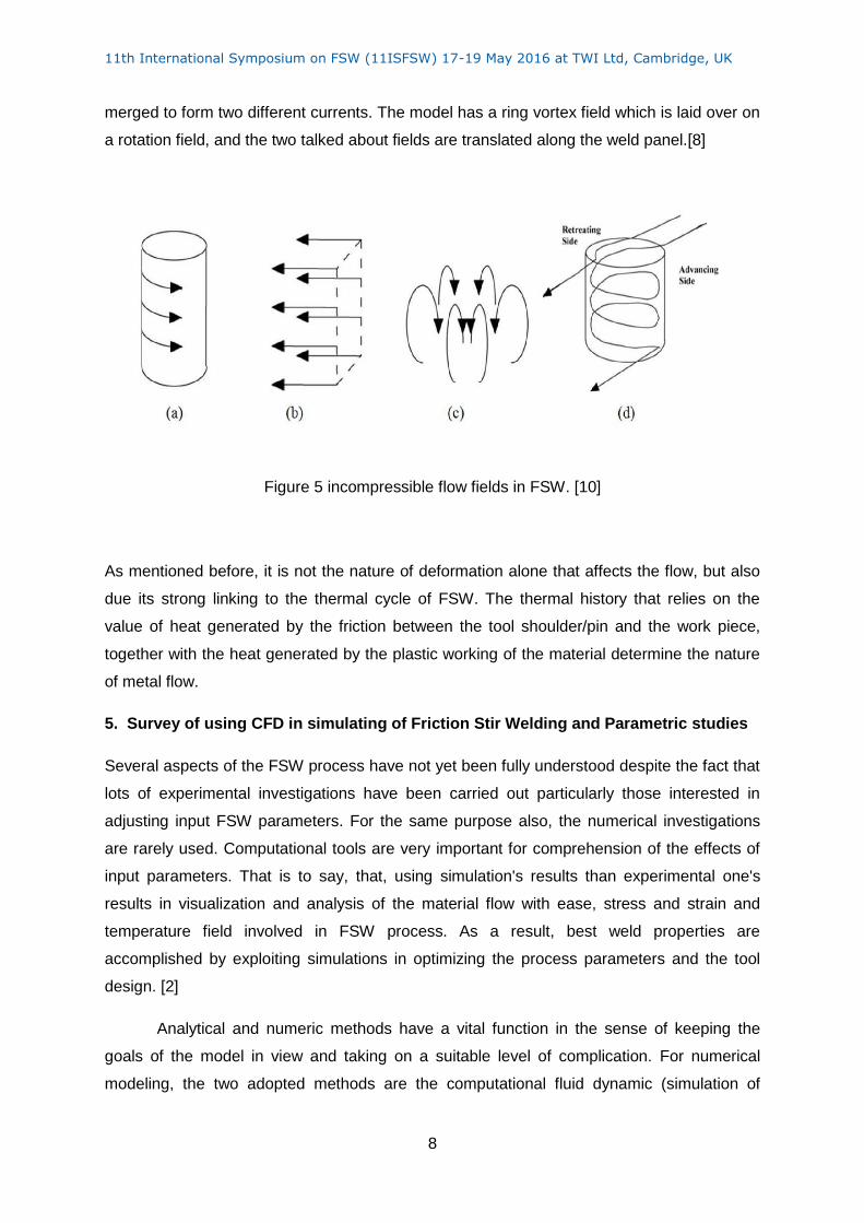
The kinematic describing of the metal motion was applied in introducing a physical model for
the metal flow. The figure below demonstrates how three incompressible flow fields are
11th International Symposium on FSW (11ISFSW) 17-19 May 2016 at TWI Ltd, Cambridge, UK
8
merged to form two different currents. The model has a ring vortex field which is laid over on
a rotation field, and the two talked about fields are translated along the weld panel.[8]
Figure 5 incompressible flow fields in FSW. [10]
As mentioned before, it is not the nature of deformation alone that affects the flow, but also
due its strong linking to the thermal cycle of FSW. The thermal history that relies on the
value of heat generated by the friction between the tool shoulder/pin and the work piece,
together with the heat generated by the plastic working of the material determine the nature
of metal flow.
5. Survey of using CFD in simulating of Friction Stir Welding and Parametric studies
Several aspects of the FSW process have not yet been fully understood despite the fact that
lots of experimental investigations have been carried out particularly those interested in
adjusting input FSW parameters. For the same purpose also, the numerical investigations
are rarely used. Computational tools are very important for comprehension of the effects of
input parameters. That is to say, that, using simulation's results than experimental one's
results in visualization and analysis of the material flow with ease, stress and strain and
temperature field involved in FSW process. As a result, best weld properties are
accomplished by exploiting simulations in optimizing the process parameters and the tool
design. [2]
Analytical and numeric methods have a vital function in the sense of keeping the
goals of the model in view and taking on a suitable level of complication. For numerical
modeling, the two adopted methods are the computational fluid dynamic (simulation of
11th International Symposium on FSW (11ISFSW) 17-19 May 2016 at TWI Ltd, Cambridge, UK
9
material flow and temperature distribution) and solid mechanics (simulation of temperature
distribution, stress and strain). Numerical FSW flow modeling is possible basing on analyses
and methods applied in the other processes like friction welding, machining, extrusion,
rolling, and forging. Since Computational Fluid Dynamic (CFD) formulations are applied in
simulation of the material flow in FSW, the material is analysed as a viscous fluid interacting
with a rotating tool and considering Eulerian mesh. About heat flow analysis, Eulerian or
Lagrangian, formulations are used by numerical flow models for the mesh. The combination
of hybrid solution and Lagrangian- Eulerian is also a way out. The mesh is mostly divided
into zones because the steep gradient of flow velocity presents complexities in the numerical
analysis. Impossibility of residual stresses predicting is a major disadvantage of CFD
models. [2]
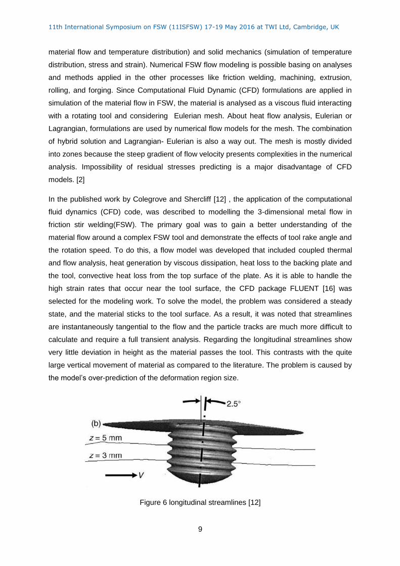
In the published work by Colegrove and Shercliff [12] , the application of the computational
fluid dynamics (CFD) code, was described to modelling the 3-dimensional metal flow in
friction stir welding(FSW). The primary goal was to gain a better understanding of the
material flow around a complex FSW tool and demonstrate the effects of tool rake angle and
the rotation speed. To do this, a flow model was developed that included coupled thermal
and flow analysis, heat generation by viscous dissipation, heat loss to the backing plate and
the tool, convective heat loss from the top surface of the plate. As it is able to handle the
high strain rates that occur near the tool surface, the CFD package FLUENT [16] was
selected for the modeling work. To solve the model, the problem was considered a steady
state, and the material sticks to the tool surface. As a result, it was noted that streamlines
are instantaneously tangential to the flow and the particle tracks are much more difficult to
calculate and require a full transient analysis. Regarding the longitudinal streamlines show
very little deviation in height as the material passes the tool. This contrasts with the quite
large vertical movement of material as compared to the literature. The problem is caused by
the model’s over-prediction of the deformation region size.
Figure 6 longitudinal streamlines [12]
11th International Symposium on FSW (11ISFSW) 17-19 May 2016 at TWI Ltd, Cambridge, UK
10
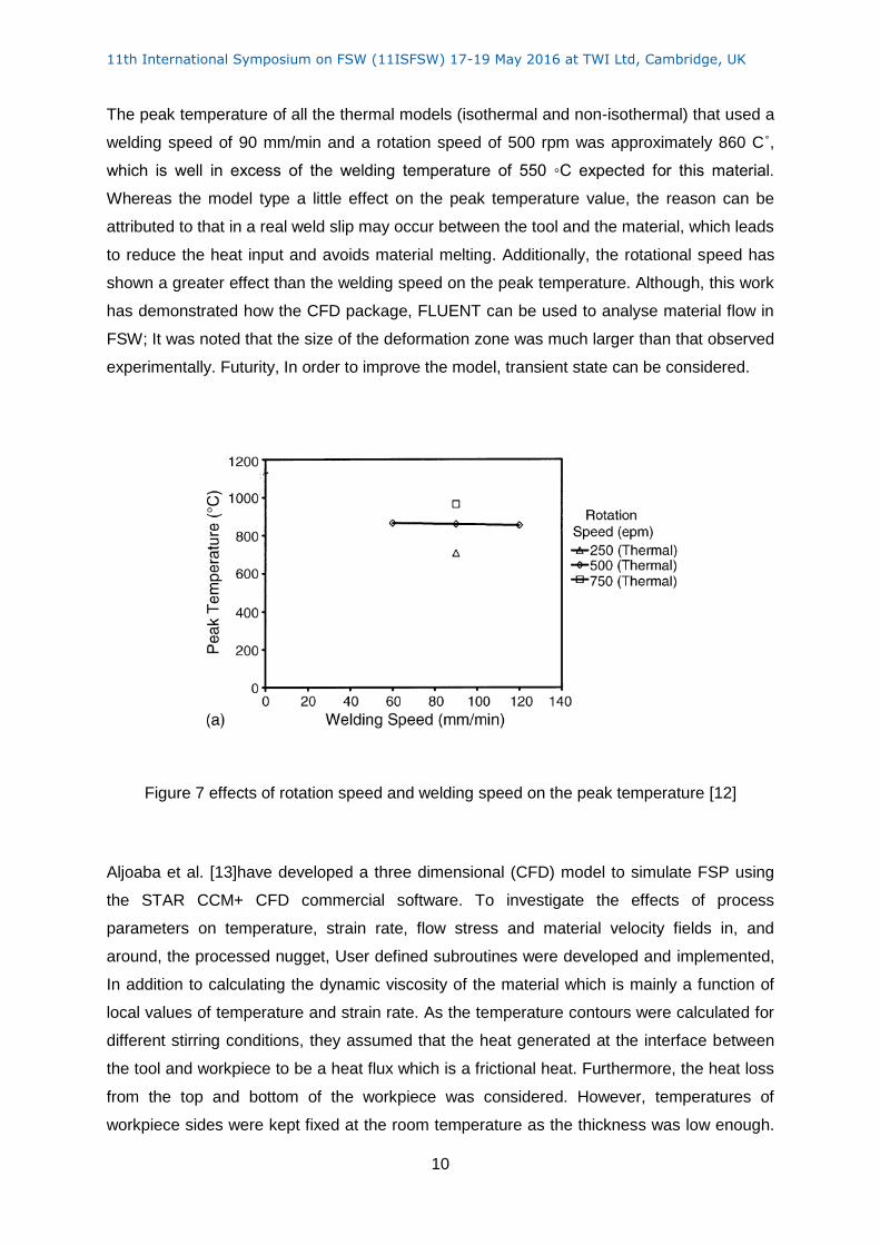
The peak temperature of all the thermal models (isothermal and non-isothermal) that used a
welding speed of 90 mm/min and a rotation speed of 500 rpm was approximately 860 C˚,
which is well in excess of the welding temperature of 550 ◦C expected for this material.
Whereas the model type a little effect on the peak temperature value, the reason can be
attributed to that in a real weld slip may occur between the tool and the material, which leads
to reduce the heat input and avoids material melting. Additionally, the rotational speed has
shown a greater effect than the welding speed on the peak temperature. Although, this work
has demonstrated how the CFD package, FLUENT can be used to analyse material flow in
FSW; It was noted that the size of the deformation zone was much larger than that observed
experimentally. Futurity, In order to improve the model, transient state can be considered.
Figure 7 effects of rotation speed and welding speed on the peak temperature [12]
Aljoaba et al. [13]have developed a three dimensional (CFD) model to simulate FSP using
the STAR CCM+ CFD commercial software. To investigate the effects of process
parameters on temperature, strain rate, flow stress and material velocity fields in, and
around, the processed nugget, User defined subroutines were developed and implemented,
In addition to calculating the dynamic viscosity of the material which is mainly a function of
local values of temperature and strain rate. As the temperature contours were calculated for
different stirring conditions, they assumed that the heat generated at the interface between
the tool and workpiece to be a heat flux which is a frictional heat. Furthermore, the heat loss
from the top and bottom of the workpiece was considered. However, temperatures of
workpiece sides were kept fixed at the room temperature as the thickness was low enough.
11th International Symposium on FSW (11ISFSW) 17-19 May 2016 at TWI Ltd, Cambridge, UK
11
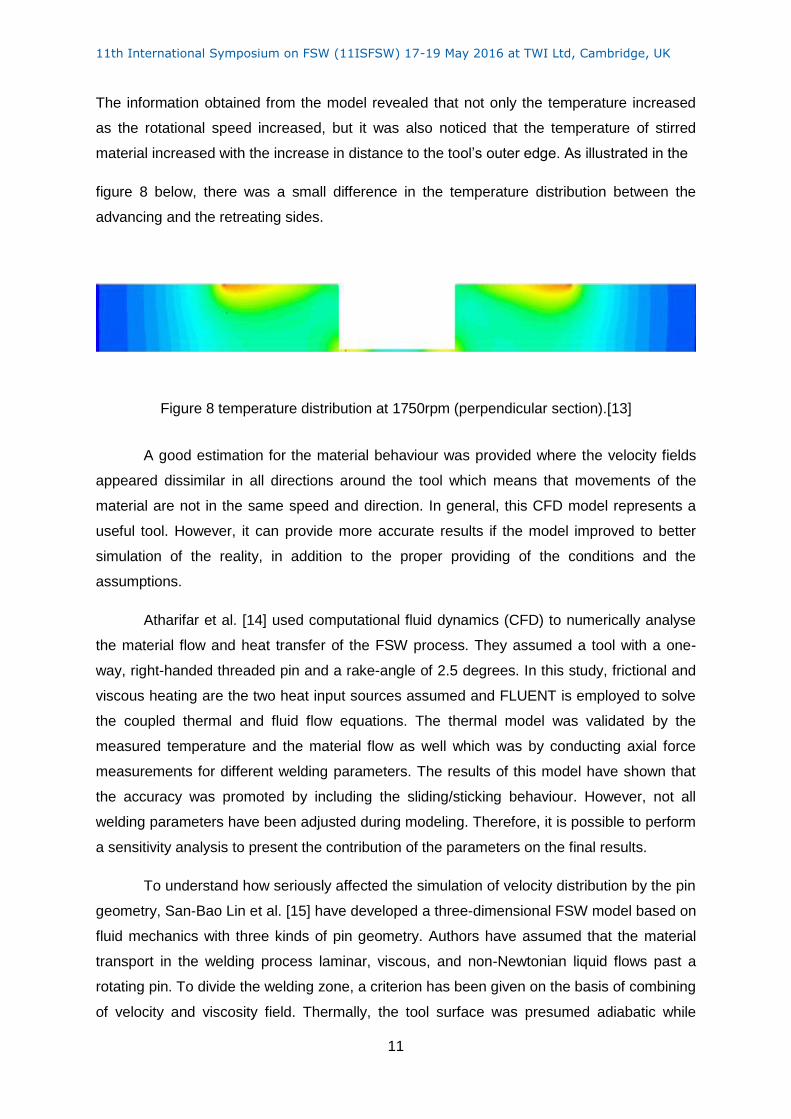
The information obtained from the model revealed that not only the temperature increased
as the rotational speed increased, but it was also noticed that the temperature of stirred
material increased with the increase in distance to the tool’s outer edge. As illustrated in the
figure 8 below, there was a small difference in the temperature distribution between the
advancing and the retreating sides.
Figure 8 temperature distribution at 1750rpm (perpendicular section).[13]
A good estimation for the material behaviour was provided where the velocity fields
appeared dissimilar in all directions around the tool which means that movements of the
material are not in the same speed and direction. In general, this CFD model represents a
useful tool. However, it can provide more accurate results if the model improved to better
simulation of the reality, in addition to the proper providing of the conditions and the
assumptions.
Atharifar et al. [14] used computational fluid dynamics (CFD) to numerically analyse
the material flow and heat transfer of the FSW process. They assumed a tool with a one-
way, right-handed threaded pin and a rake-angle of 2.5 degrees. In this study, frictional and
viscous heating are the two heat input sources assumed and FLUENT is employed to solve
the coupled thermal and fluid flow equations. The thermal model was validated by the
measured temperature and the material flow as well which was by conducting axial force
measurements for different welding parameters. The results of this model have shown that
the accuracy was promoted by including the sliding/sticking behaviour. However, not all
welding parameters have been adjusted during modeling. Therefore, it is possible to perform
a sensitivity analysis to present the contribution of the parameters on the final results.
To understand how seriously affected the simulation of velocity distribution by the pin
geometry, San-Bao Lin et al. [15] have developed a three-dimensional FSW model based on
fluid mechanics with three kinds of pin geometry. Authors have assumed that the material
transport in the welding process laminar, viscous, and non-Newtonian liquid flows past a
rotating pin. To divide the welding zone, a criterion has been given on the basis of combining
of velocity and viscosity field. Thermally, the tool surface was presumed adiabatic while
11th International Symposium on FSW (11ISFSW) 17-19 May 2016 at TWI Ltd, Cambridge, UK
12
there was a convective heat transfer from all workpiece sides. As the simulation result well
agreed with the “marker insert technique” experiments. That mean the flow zone can be
considered as the criterion to optimize the friction stir tool design.
In an advanced step, a three-dimensional transient (CFD) model of FSW of Mg alloy
was proposed by Zhenzhen Yu et al.[16] The model was to investigate the material flow and
heat transfer during FSW process and to build this model; there have been assumptions
such as considering the material to be a non-Newtonian viscoplastic fluid, and the Zener-
Hollomon Parameter has been used to define the dependency of the viscosity on the
temperature and the strain rate. To capture the material flow induced by the movement of
the threaded tool pin, a dynamic mesh method, combining both Lagrangian and Eulerian
formulations was used. Moreover, in the simulation domain and to track the detailed history
of material flow, massless inert particles were embedded.
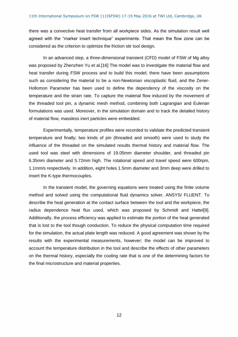
Experimentally, temperature profiles were recorded to validate the predicted transient
temperature and finally; two kinds of pin (threaded and smooth) were used to study the
influence of the threaded on the simulated results thermal history and material flow. The
used tool was steel with dimensions of 19.05mm diameter shoulder, and threaded pin
6.35mm diameter and 5.72mm high. The rotational speed and travel speed were 600rpm,
1.1mm/s respectively. In addition, eight holes 1.5mm diameter and 3mm deep were drilled to
insert the K-type thermocouples.
In the transient model, the governing equations were treated using the finite volume
method and solved using the computational fluid dynamics solver, ANSYS/ FLUENT. To
describe the heat generation at the contact surface between the tool and the workpiece, the
radius dependence heat flux used, which was proposed by Schmidt and Hattel[9].
Additionally, the process efficiency was applied to estimate the portion of the heat generated
that is lost to the tool though conduction. To reduce the physical computation time required
for the simulation, the actual plate length was reduced. A good agreement was shown by the
results with the experimental measurements, however; the model can be improved to
account the temperature distribution in the tool and describe the effects of other parameters
on the thermal history, especially the cooling rate that is one of the determining factors for
the final microstructure and material properties.
11th International Symposium on FSW (11ISFSW) 17-19 May 2016 at TWI Ltd, Cambridge, UK
13
Figure 9 measured and predicted temperature profiles corresponding positions [16]
In the work that carried out by H. Mohanty et al. [17] a CFD model using FLUENT
software was introduced to analyse of material flow and heat transfer of series 1100
aluminium alloy, with respect to different tool geometries. In this model, the partial slip-stick
condition of heat generation was incorporated and in order to reduce the simulation time; the
dimensions of the computational region were smaller than those used for the plates in the in
the experimental work. Heat convection between workpiece and the surrounding was
assumed and the conduction heat transfer to the tool as well. But heat transferred to the
supporting tables was ignored. The CFD solver condition was set to be laminar and steady.
Although the results depicted most features of the FSW, the model can be improved by
replacing the assumptions were taken by others that are more realistic.
In terms of quantitatively describing the three-dimensional material flows, FSW
process with a conical pin was simulated by W.U.Chuan-song et al. [18] the computed
results were compared with FSW experiments of 2024 Al alloy that were conducted using
marker inserted method and evaluated in metallographic ways. The model assumes that the
material sticks to the tool surface, so the material velocity is the same as the tool surface.
The calculated overall mode of material flow was consistent with the visualized results.
However, authors assumed that the pin surface as an adiabatic wall.
In order to account for material softening phenomena at elevated temperatures and
extremely high strain rates that occur during the FSP process, A.N.Albakri et al. [19]
experimentally measured peak temperatures were utilized to introduce a correction function
in the flow stress constitutive relation. That was inserted in the CFD, fully coupled, 3D,
thermo-mechanical model, which was built to understand the effects of FSW process
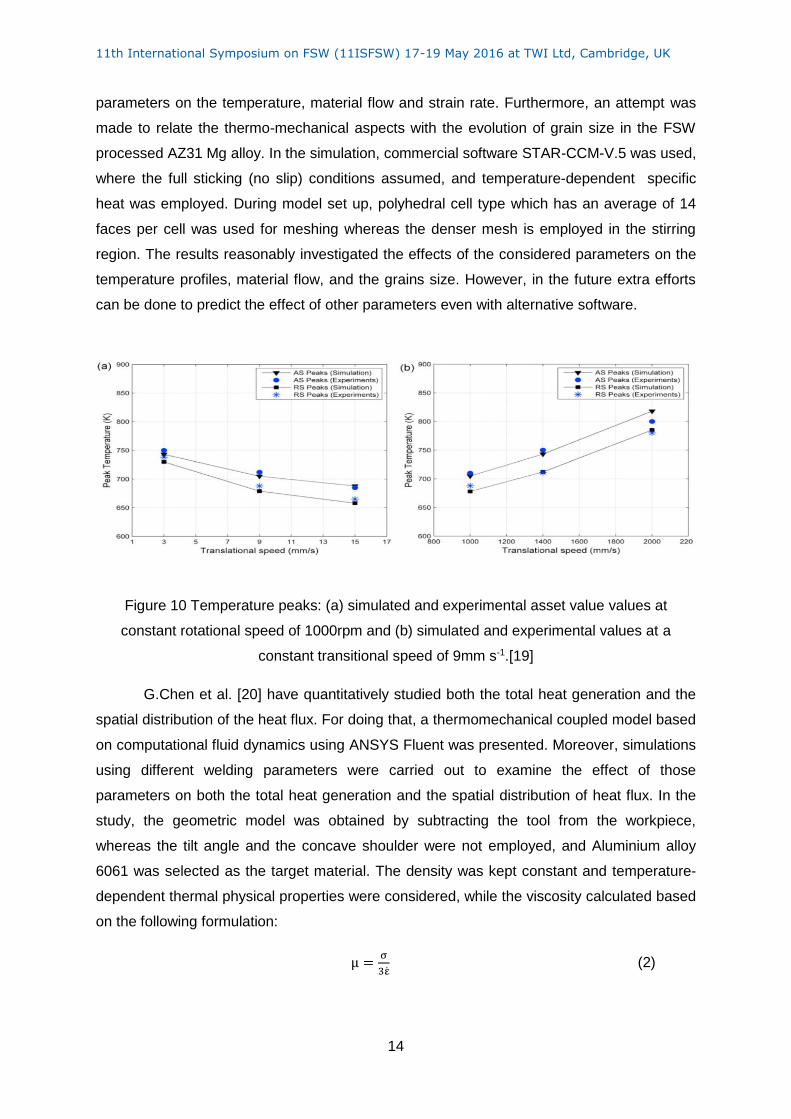
11th International Symposium on FSW (11ISFSW) 17-19 May 2016 at TWI Ltd, Cambridge, UK
14
parameters on the temperature, material flow and strain rate. Furthermore, an attempt was
made to relate the thermo-mechanical aspects with the evolution of grain size in the FSW
processed AZ31 Mg alloy. In the simulation, commercial software STAR-CCM-V.5 was used,
where the full sticking (no slip) conditions assumed, and temperature-dependent specific
heat was employed. During model set up, polyhedral cell type which has an average of 14
faces per cell was used for meshing whereas the denser mesh is employed in the stirring
region. The results reasonably investigated the effects of the considered parameters on the
temperature profiles, material flow, and the grains size. However, in the future extra efforts
can be done to predict the effect of other parameters even with alternative software.
Figure 10 Temperature peaks: (a) simulated and experimental asset value values at
constant rotational speed of 1000rpm and (b) simulated and experimental values at a
constant transitional speed of 9mm s-1.[19]
G.Chen et al. [20] have quantitatively studied both the total heat generation and the
spatial distribution of the heat flux. For doing that, a thermomechanical coupled model based
on computational fluid dynamics using ANSYS Fluent was presented. Moreover, simulations
using different welding parameters were carried out to examine the effect of those
parameters on both the total heat generation and the spatial distribution of heat flux. In the
study, the geometric model was obtained by subtracting the tool from the workpiece,
whereas the tilt angle and the concave shoulder were not employed, and Aluminium alloy
6061 was selected as the target material. The density was kept constant and temperature-
dependent thermal physical properties were considered, while the viscosity calculated based
on the following formulation:
μ =σ
3ε̇ (2)
11th International Symposium on FSW (11ISFSW) 17-19 May 2016 at TWI Ltd, Cambridge, UK
15
Where, σ is the flow stress and ε̇ is the strain rate. The relationship between the total heat
generation and the rotating rate was found to be proportional to ω0.75 and a radial distribution
function was defined to describe the heat flux. Furthermore, the model could show the slight
difference between the temperature on the advancing side and the retreating side.
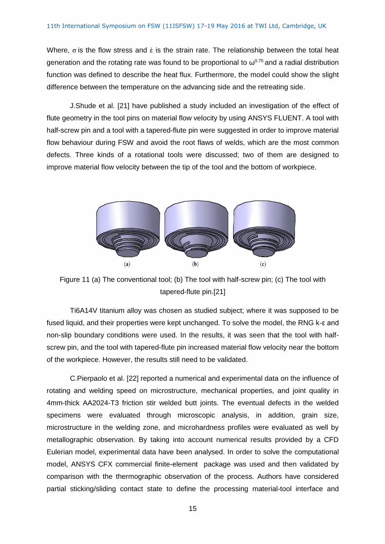
J.Shude et al. [21] have published a study included an investigation of the effect of
flute geometry in the tool pins on material flow velocity by using ANSYS FLUENT. A tool with
half-screw pin and a tool with a tapered-flute pin were suggested in order to improve material
flow behaviour during FSW and avoid the root flaws of welds, which are the most common
defects. Three kinds of a rotational tools were discussed; two of them are designed to
improve material flow velocity between the tip of the tool and the bottom of workpiece.
Figure 11 (a) The conventional tool; (b) The tool with half-screw pin; (c) The tool with
tapered-flute pin.[21]
Ti6A14V titanium alloy was chosen as studied subject; where it was supposed to be
fused liquid, and their properties were kept unchanged. To solve the model, the RNG k-ε and
non-slip boundary conditions were used. In the results, it was seen that the tool with half-
screw pin, and the tool with tapered-flute pin increased material flow velocity near the bottom
of the workpiece. However, the results still need to be validated.
C.Pierpaolo et al. [22] reported a numerical and experimental data on the influence of
rotating and welding speed on microstructure, mechanical properties, and joint quality in
4mm-thick AA2024-T3 friction stir welded butt joints. The eventual defects in the welded
specimens were evaluated through microscopic analysis, in addition, grain size,
microstructure in the welding zone, and microhardness profiles were evaluated as well by
metallographic observation. By taking into account numerical results provided by a CFD
Eulerian model, experimental data have been analysed. In order to solve the computational
model, ANSYS CFX commercial finite-element package was used and then validated by
comparison with the thermographic observation of the process. Authors have considered
partial sticking/sliding contact state to define the processing material-tool interface and
11th International Symposium on FSW (11ISFSW) 17-19 May 2016 at TWI Ltd, Cambridge, UK
16
modelled the heat generation due to frictional effects and plastic deformation as a heat flux
applied on shoulder and pin contact surfaces. The heat flux formula was written by
considering the Treska model (𝜇f𝑝 = 𝑚𝜏𝑦) as follows
𝑞 = 𝜂𝑚𝛿𝜔𝑟𝜏𝑦 + (1 − 𝛿)𝜂𝑤𝜔𝑟𝜇f𝑝 (3)
𝑞 = 𝜔𝑟𝜏𝑦(𝜂𝑚 𝛿 + 𝜂 𝑤𝑚(1 − 𝛿)) (4)
Where, r the radial distance from the tool axis, 𝜇f the friction coefficient, 𝑝 The
contact pressure, τy the yielding shear stress, m the proportional coefficient, ηm the
mechanical efficiency (amount of mechanical energy dissipated as heat),and 𝜂 𝑤 the
frictional heat transferred to the workpiece.
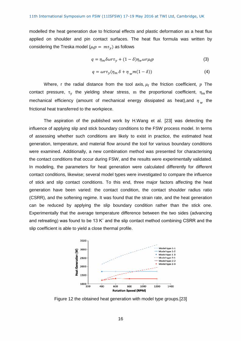
The aspiration of the published work by H.Wang et al. [23] was detecting the
influence of applying slip and stick boundary conditions to the FSW process model. In terms
of assessing whether such conditions are likely to exist in practice, the estimated heat
generation, temperature, and material flow around the tool for various boundary conditions
were examined. Additionally, a new combination method was presented for characterising
the contact conditions that occur during FSW, and the results were experimentally validated.
In modeling, the parameters for heat generation were calculated differently for different
contact conditions, likewise; several model types were investigated to compare the influence
of stick and slip contact conditions. To this end, three major factors affecting the heat
generation have been varied: the contact condition, the contact shoulder radius ratio
(CSRR), and the softening regime. It was found that the strain rate, and the heat generation
can be reduced by applying the slip boundary condition rather than the stick one.
Experimentally that the average temperature difference between the two sides (advancing
and retreating) was found to be 13 K˚ and the slip contact method combining CSRR and the
slip coefficient is able to yield a close thermal profile.
Figure 12 the obtained heat generation with model type groups.[23]
11th International Symposium on FSW (11ISFSW) 17-19 May 2016 at TWI Ltd, Cambridge, UK
17
H.H.Cho et al. [24] utilised an Eulerian finite volume under steady-state conditions to
simulate FSW processes are carried out for 409 ferritic stainless steel, then with the
measured temperature and obtained microstructure; the simulation results were compared.
Spatially variable heat generation rates and non-Newtonian viscosity were considered in the
model as a function of local strain rate, temperature and characteristics of material. Likewise,
the texture around the FSW tool was predicted from the computed velocity gradients along
the streamlines of the flow field by using a viscoplastic self-consistent (VPSC) approach for
polycrystal. Researchers considered the partial sticking contact condition and dependent
temperature properties. Thus, all formulations were incorporated into a FLUENT using a
user defined function (UDF). Moreover, formula for the heat generated at the interface
between the vertical and horizontal surfaces of the tool, and the workpiece was given and
the fractional slip as well. Although, the model used to demonstrate sufficient possibilities,
some assumptions that taken in the account could be weaknesses the model or cause
uncertainty of the results.
Using CFD package, Fluent; a model was established by G.Q.Chen et al. [25] based
on the interactive force between the tool and the material. The heat generation, temperature
distribution, were calculated and experimentally verified while the velocity on the tool
material boundary, and the shape of the stir zone is investigated based on the simulation
results. The authors assumed that the quasi-steady state was reached during the process.
However, the boundary between the workpiece on the advancing and retreating sides was
not considered. The tetragonal grids were used to mesh the calculation domain and the heat
dissipation to the air and the fixtures were assumed. It’s noteworthy in the model that the
interactive shear stress on the boundary was assumed to be equal to the shear flow stress
of the material next to the boundary, which depended on the temperature and strain rate of
the adjacent material. Accordingly, as a vector; the shear stress direction at the boundary
was defined by the relative velocity vector between the tool and the adjacent material.
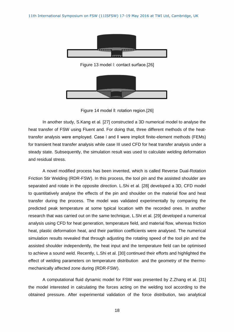
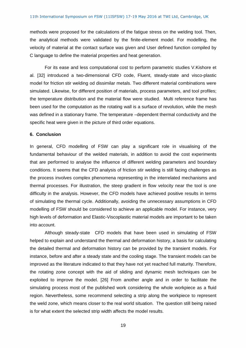
As defining the fluid region in FSW simulation is a key issue for an accurate
modeling, S.Kang et al. [26] modelled FSW by imposing a rotational affected zone. In this
research, a CFD finite volume method (FVM) with the Eulerian description approach was
implemented beside the full sticking condition. Two models were assumed to define the
rotational zone, the first one is in which only the contact area is forced to rotate, and the
plastic zone grows as heat spreads; while the second is in which the rotational region around
the tool was defined as plastic deformation zone and named rotation affected zone(RAZ).
Additionally, a parametric study was carried out for finding out the best shape of the (RAZ).
11th International Symposium on FSW (11ISFSW) 17-19 May 2016 at TWI Ltd, Cambridge, UK
18
Figure 13 model ǀ: contact surface.[26]
Figure 14 model ǁ: rotation region.[26]
In another study, S.Kang et al. [27] constructed a 3D numerical model to analyse the
heat transfer of FSW using Fluent and. For doing that, three different methods of the heat-
transfer analysis were employed. Case ǀ and ǁ were implicit finite-element methods (FEMs)
for transient heat transfer analysis while case III used CFD for heat transfer analysis under a
steady state. Subsequently, the simulation result was used to calculate welding deformation
and residual stress.
A novel modified process has been invented, which is called Reverse Dual-Rotation
Friction Stir Welding (RDR-FSW). In this process, the tool pin and the assisted shoulder are
separated and rotate in the opposite direction. L.Shi et al. [28] developed a 3D, CFD model
to quantitatively analyse the effects of the pin and shoulder on the material flow and heat
transfer during the process. The model was validated experimentally by comparing the
predicted peak temperature at some typical location with the recorded ones. In another
research that was carried out on the same technique, L.Shi et al. [29] developed a numerical
analysis using CFD for heat generation, temperature field, and material flow, whereas friction
heat, plastic deformation heat, and their partition coefficients were analysed. The numerical
simulation results revealed that through adjusting the rotating speed of the tool pin and the
assisted shoulder independently, the heat input and the temperature field can be optimised
to achieve a sound weld. Recently, L.Shi et al. [30] continued their efforts and highlighted the
effect of welding parameters on temperature distribution and the geometry of the thermo-
mechanically affected zone during (RDR-FSW).
A computational fluid dynamic model for FSW was presented by Z.Zhang et al. [31]
the model interested in calculating the forces acting on the welding tool according to the
obtained pressure. After experimental validation of the force distribution, two analytical
11th International Symposium on FSW (11ISFSW) 17-19 May 2016 at TWI Ltd, Cambridge, UK
19
methods were proposed for the calculations of the fatigue stress on the welding tool. Then,
the analytical methods were validated by the finite-element model. For modelling, the
velocity of material at the contact surface was given and User defined function compiled by
C language to define the material properties and heat generation.
For its ease and less computational cost to perform parametric studies V.Kishore et
al. [32] introduced a two-dimensional CFD code, Fluent, steady-state and visco-plastic
model for friction stir welding od dissimilar metals. Two different material combinations were
simulated. Likewise, for different position of materials, process parameters, and tool profiles;
the temperature distribution and the material flow were studied. Multi reference frame has
been used for the computation as the rotating wall is a surface of revolution, while the mesh
was defined in a stationary frame. The temperature –dependent thermal conductivity and the
specific heat were given in the picture of third order equations.
6. Conclusion
In general, CFD modelling of FSW can play a significant role in visualising of the
fundamental behaviour of the welded materials, in addition to avoid the cost experiments
that are performed to analyse the influence of different welding parameters and boundary
conditions. It seems that the CFD analysis of friction stir welding is still facing challenges as
the process involves complex phenomena representing in the interrelated mechanisms and
thermal processes. For illustration, the steep gradient in flow velocity near the tool is one
difficulty in the analysis. However, the CFD models have achieved positive results in terms
of simulating the thermal cycle. Additionally, avoiding the unnecessary assumptions in CFD
modelling of FSW should be considered to achieve an applicable model. For instance, very
high levels of deformation and Elastic-Viscoplastic material models are important to be taken
into account.
Although steady-state CFD models that have been used in simulating of FSW
helped to explain and understand the thermal and deformation history, a basis for calculating
the detailed thermal and deformation history can be provided by the transient models. For
instance, before and after a steady state and the cooling stage. The transient models can be
improved as the literature indicated to that they have not yet reached full maturity. Therefore,
the rotating zone concept with the aid of sliding and dynamic mesh techniques can be
exploited to improve the model. [26] From another angle and in order to facilitate the
simulating process most of the published work considering the whole workpiece as a fluid
region. Nevertheless, some recommend selecting a strip along the workpiece to represent
the weld zone, which means closer to the real world situation. The question still being raised
is for what extent the selected strip width affects the model results.

11th International Symposium on FSW (11ISFSW) 17-19 May 2016 at TWI Ltd, Cambridge, UK
20
Regarding using CFD based tools in optimisation of FSW parameters; some defects
that could practically take place, which cannot be modelled and the high computational costs
are still the main reasons for the lack of the optimization studies. Conversely, as the
processors are witnessing continual improvements, there might be an opportunity to conduct
the costly computational processes, particularly with employment of the practical limitations
of the process parameters which in role replacing the experimental trials actually used and
promoting to use FSW in a wider range of applications. So far, the optimisation studies
have remained largely based on the experimental data.
11th International Symposium on FSW (11ISFSW) 17-19 May 2016 at TWI Ltd, Cambridge, UK
21
References
1. Institute, T.W. Friction Stir Welding Benefits and Advantages. 2014; Available from: http://www.twi-global.com/capabilities/joining-technologies/friction-processes/friction-stir-welding/benefits-and-advantages/.
2. Neto, D.M. and P. Neto, Numerical modeling of friction stir welding process: a literature review. The International Journal of Advanced Manufacturing Technology, 2013. 65(1-4): p. 115-126.
3. Leal, R.M., et al., Material flow in heterogeneous friction stir welding of thin aluminium sheets: Effect of shoulder geometry. Materials Science & Engineering A, 2008. 498(1): p. 384-391.
4. Li, W.Y., et al., Metal Flow during Friction Stir Welding of 7075-T651 Aluminum Alloy. Experimental Mechanics, 2013. 53(9): p. 1573-1582.
5. Wang, N., Transient Temperature Distributio in Inertia Welding of Steel. Welding Research Supplement, 1970: p. 8.
6. Blondeau, R.g., Metallurgy and mechanics of welding: processes and industrial applications2008, Hoboken, N.J; London: ISTE, Wiley.
7. Mishra, R.S. and Z.Y. Ma, Friction stir welding and processing. Materials Science and Engineering: R: Reports, 2005. 50(1–2): p. 1-78.
8. Schneider, J. and A. Nunes, Characterization of plastic flow and resulting microtextures in a friction stir weld. Metallurgical and Materials Transactions B, 2004. 35(4): p. 777-783.
9. Schmidt, H., J. Hattel, and J. Wert, An analytical model for the heat generation in friction stir welding. Modelling and Simulation in Materials Science and Engineering, 2004. 12(1): p. 143.
10. Mishra, R.S., P.S. De, and N. Kumar, Friction Stir Welding and Processing : Science and Engineering. Vol. 1; 2014. 2014, Cham: Springer.
11. Reilly, A., Modelling of friction stir spot welding, 2013, University of Cambridge. 12. Colegrove, P.A. and H.R. Shercliff, 3-Dimensional CFD modelling of flow round a
threaded friction stir welding tool profile. Journal of Materials Processing Tech, 2005. 169(2): p. 320-327.
13. Aljoaba, S.Z., et al., Modeling of friction stir processing using 3D CFD analysis. International Journal of Material Forming, 2009. 2(S1): p. 315-318.
14. Atharifar, H., D. Lin, and R. Kovacevic, Numerical and Experimental Investigations on the Loads Carried by the Tool During Friction Stir Welding. Journal of Materials Engineering and Performance, 2009. 18(4): p. 339-350.
15. San-Bao, L.I.N.Y.-H.Z.Z.-Q.H.E.L.W.U., Modeling of friction stir welding process for
tools design. 材料学前沿:英文版, 2011. 5(2): p. 236-245.
16. Yu, Z., et al., Transient Heat and Material Flow Modeling of Friction Stir Processing of Magnesium Alloy using Threaded Tool. Metallurgical and Materials Transactions A, 2012. 43(2): p. 724-737.
17. Mohanty, H., et al., Study on the effect of tool profiles on temperature distribution and material flow characteristics in friction stir welding. Proceedings of the Institution of Mechanical Engineers, Part B: Journal of Engineering Manufacture, 2012. 226(9): p. 1527-1535.
18. Wu, C.-S., et al., Visualization and simulation of plastic material flow in friction stir welding of 2024 aluminium alloy plates. Transactions of Nonferrous Metals Society of China (English Edition), 2012. 22(6): p. 1445-1451.
19. Albakri, A.N., et al., Thermo-mechanical and metallurgical aspects in friction stir processing of AZ31 Mg alloy - A numerical and experimental investigation. Journal of Materials Processing Technology, 2013. 213(2): p. 279-290.
11th International Symposium on FSW (11ISFSW) 17-19 May 2016 at TWI Ltd, Cambridge, UK
22
20. Chen, G.-Q., et al., Computational fluid dynamics studies on heat generation during friction stir welding of aluminum alloy. Computational Materials Science, 2013. 79(Journal Article): p. 540-546.
21. Ji, S., et al., Design of friction stir welding tool for avoiding root flaws. Materials, 2013. 6(12): p. 5870-5877.
22. Carlone, P. and G.S. Palazzo, Influence of Process Parameters on Microstructure and Mechanical Properties in AA2024-T3 Friction Stir Welding. Metallography, Microstructure, and Analysis, 2013. 2(4): p. 213-222.
23. Wang, H., P.A. Colegrove, and J.F. Dos Santos, Numerical investigation of the tool contact condition during friction stir welding of aerospace aluminium alloy. Computational Materials Science, 2013. 71(Journal Article): p. 101-108.
24. Cho, H.-H., et al., Three-dimensional numerical and experimental investigation on friction stir welding processes of ferritic stainless steel. Acta Materialia, 2013. 61(7): p. 2649-2661.
25. Chen, G.Q., et al., Simulation of Metal Flow During Friction Stir Welding Based on the Model of Interactive Force Between Tool and Material. Journal of Materials Engineering and Performance, 2014. 23(4): p. 1321-1328.
26. Kang, S.-W., B.-S. Jang, and J.-W. Kim, A study on heat-flow analysis of friction stir welding on a rotation affected zone. Journal of Mechanical Science and Technology, 2014. 28(9): p. 3873-3883.
27. Kang, S.-W. and B.-S. Jang, Comparison of friction stir welding heat transfer analysis methods and parametric study on unspecified input variables. Journal of Mechanical Science and Technology, 2014. 28(10): p. 4233-4246.
28. Shi, L., C.S. Wu, and H.J. Liu, Modeling the Material Flow and Heat Transfer in Reverse Dual-Rotation Friction Stir Welding. Journal of Materials Engineering and Performance, 2014. 23(8): p. 2918-2929.
29. Shi, L., C.S. Wu, and H.J. Liu, Numerical analysis of heat generation and temperature field in reverse dual-rotation friction stir welding. The International Journal of Advanced Manufacturing Technology, 2014. 74(1): p. 319-334.
30. Shi, L., C.S. Wu, and H.J. Liu, Analysis of heat transfer and material flow in reverse dual-rotation friction stir welding. Welding in the World, 2015. 59(5): p. 629-638.
31. Zhang, Z. and Q. Wu, Analytical and numerical studies of fatigue stresses in friction stir welding. The International Journal of Advanced Manufacturing Technology, 2015. 78(9): p. 1371-1380.
32. Kishore, V.R., et al., Parametric studies of dissimilar friction stir welding using computational fluid dynamics simulation. International Journal of Advanced Manufacturing Technology, 2015(Journal Article).