University of Calgary – CPSC 441. We need to break down big networks to sub-LANs Limited amount...
23
Hubs, Switches and Bridges University of Calgary – CPSC 441
-
Upload
cristopher-meddock -
Category
Documents
-
view
215 -
download
1
Transcript of University of Calgary – CPSC 441. We need to break down big networks to sub-LANs Limited amount...
Hubs, Switches and Bridges
University of Calgary – CPSC 441
2
LAN Interconnection
We need to break down big networks to sub-LANs Limited amount of supportable traffic: on single LAN, all
stations must share bandwidth
Limited length: 802.3 (Ethernet) specifies maximum cable length. For 10 Mbps:▪ Maximum length of the wire: 2,500 meter
Large “collision domain” (can collide with many stations)
3
HUBS
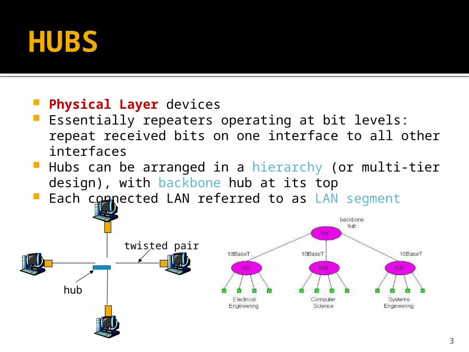
Physical Layer devices Essentially repeaters operating at bit levels: repeat
received bits on one interface to all other interfaces Hubs can be arranged in a hierarchy (or multi-tier design),
with backbone hub at its top Each connected LAN referred to as LAN segment
twisted pair
hub
4
Hubs: Pros and Cons
Hub Advantages: simple, inexpensive device Multi-tier provides graceful degradation: portions of the LAN
continue to operate if one hub malfunctions extends maximum distance between node pairs (100m per Hub)
Hubs do not isolate collision domains: node may collide with any node residing at any segment in LAN Single collision domain results in no increase in max throughput multi-tier throughput same as single segment throughput Individual LAN restrictions pose limits on number of nodes in same
collision domain and on total allowed geographical coverage cannot connect different Ethernet types (e.g., 10BaseT and
100baseT) Why?
5
Bridges
Link-layer devices: store, forward Ethernet frames examine incoming frame’s MAC address, selectively forward
frame to one-or-more outgoing links when frame is to be forwarded on segment, uses CSMA/CD to access segment
Advantages: Isolates collision domains resulting in higher total max throughput, and
does not limit the number of nodes nor geographical coverage Can connect different type Ethernet since it is a store and forward
device Transparent: no need for any change to hosts LAN adapters
6
Switches
A switch could be considered a bridge with numerous ports.
Switch or Layer 2 switch is often used interchangeably with bridge
Plug-and-play, self-learning switches do not need to be configured
7
Switch: allows multiple simultaneous transmissions
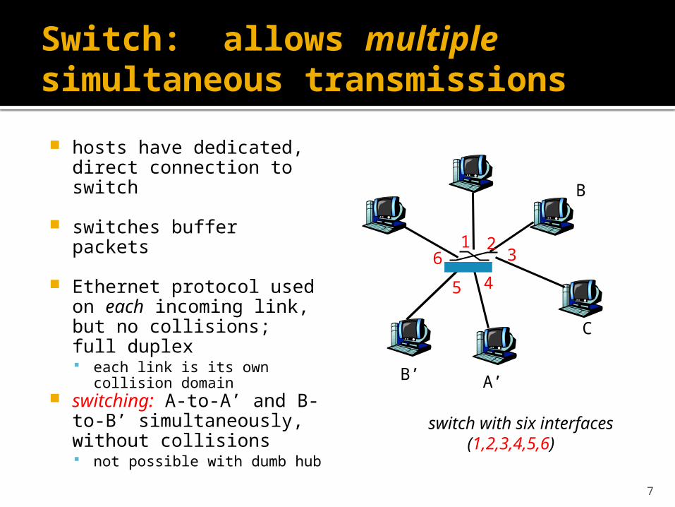
hosts have dedicated, direct connection to switch
switches buffer packets
Ethernet protocol used on each incoming link, but no collisions; full duplex each link is its own collision
domain switching: A-to-A’ and B-
to-B’ simultaneously, without collisions not possible with dumb hub
A’
B
B’
C
switch with six interfaces(1,2,3,4,5,6)
1 23
45
6
8
Switch Table
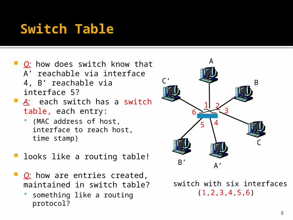
Q: how does switch know that A’ reachable via interface 4, B’ reachable via interface 5?
A: each switch has a switch table, each entry: (MAC address of host, interface
to reach host, time stamp)
looks like a routing table!
Q: how are entries created, maintained in switch table? something like a routing
protocol?
A
A’
B
B’
C
C’
switch with six interfaces(1,2,3,4,5,6)
1 23
45
6
9
Switch: self-learning
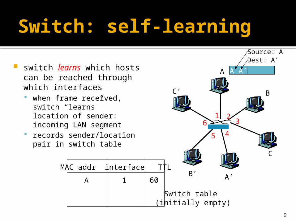
switch learns which hosts can be reached through which interfaces when frame received, switch
“learns” location of sender: incoming LAN segment
records sender/location pair in switch table
A
A’
B
B’
C
C’
1 23
45
6
A A’
Source: ADest: A’
MAC addr interface TTL
Switch table (initially empty)
A 1 60
10
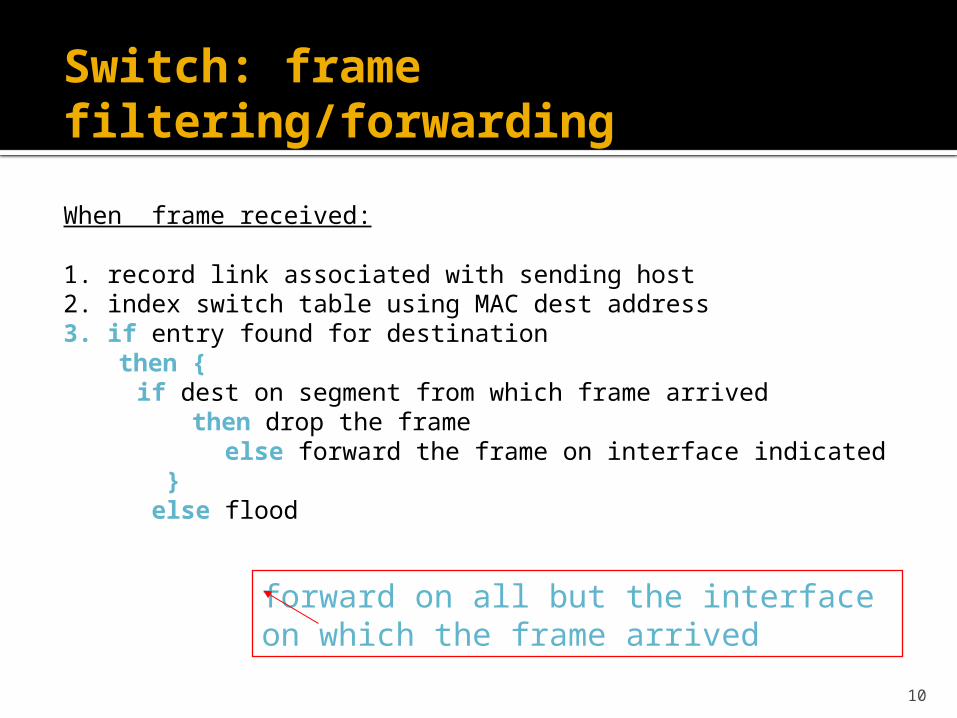
Switch: frame filtering/forwarding
When frame received:
1. record link associated with sending host2. index switch table using MAC dest address3. if entry found for destination
then { if dest on segment from which frame arrived
then drop the frame else forward the frame on interface indicated } else flood
forward on all but the interface on which the frame arrived
11
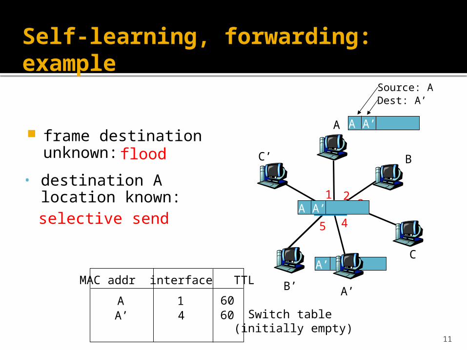
Self-learning, forwarding: example
A
A’
B
B’
C
C’
1 23
45
6
A A’
Source: ADest: A’
MAC addr interface TTL
Switch table (initially empty)
A 1 60
A A’A A’A A’A A’A A’
frame destination unknown: flood
A’ A
• destination A location known:
A’ 4 60
selective send
12
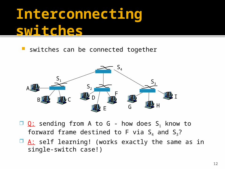
Interconnecting switches
switches can be connected together
A
B
Q: sending from A to G - how does S1 know to forward frame destined to F via S4 and S3?
A: self learning! (works exactly the same as in single-switch case!)
S1
C D
E
FS2
S4
S3
H
I
G
13
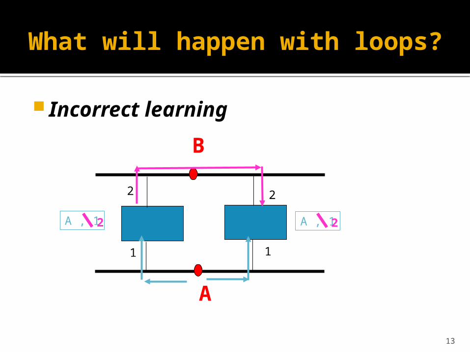
What will happen with loops?
Incorrect learning
A
B
1 1
22
A , 1 A , 122
14
Spanning Trees
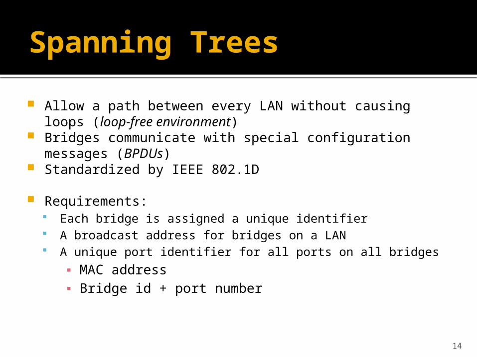
Allow a path between every LAN without causing loops (loop-free environment)
Bridges communicate with special configuration messages (BPDUs)
Standardized by IEEE 802.1D
Requirements: Each bridge is assigned a unique identifier A broadcast address for bridges on a LAN A unique port identifier for all ports on all bridges
▪ MAC address▪ Bridge id + port number
15
Example Spanning Tree
B3
B5
B7B2
B1
B6 B4
Root
B8
Designated Bridge
Root port
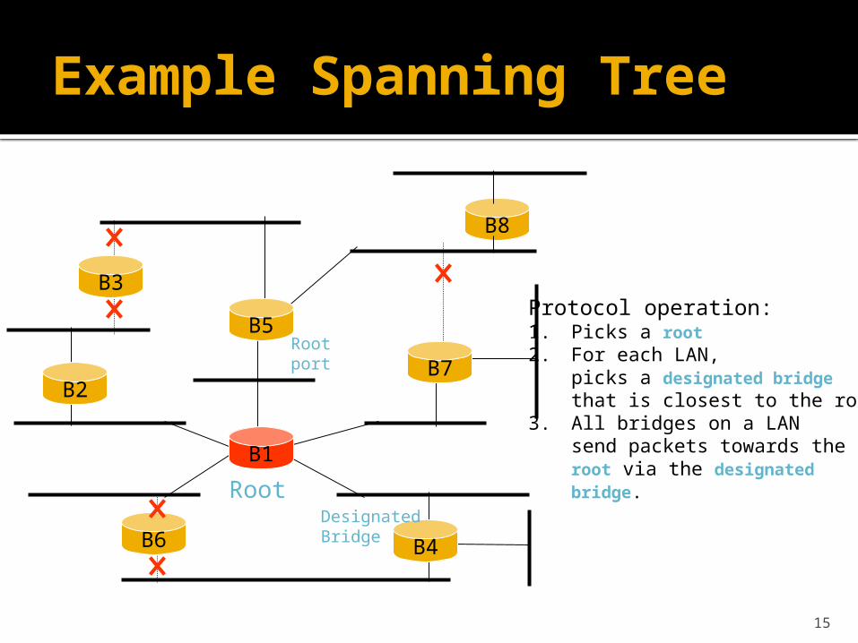
Protocol operation:1. Picks a root2. For each LAN,
picks a designated bridgethat is closest to the root.
3. All bridges on a LANsend packets towards the root via the designated bridge.
16
Example Spanning Tree
B3
B5
B7B2
B1
B6 B4
Root
B8
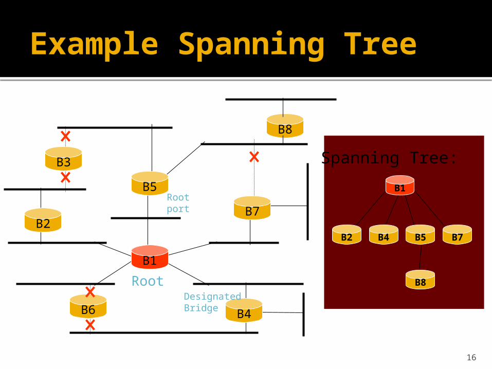
B2 B4 B5 B7
B8
B1
Spanning Tree:
Designated Bridge
Root port
17
Spanning Tree Algorithm:overview
1. Determine the root bridge among all bridges
2. Each bridge determines its root port The port in the direction of the root bridge
3. Determine the designated bridge on each LAN
The bridge which accepts frames to forward towards the root bridge
The frames are sent on the root port of the designated bridge
18
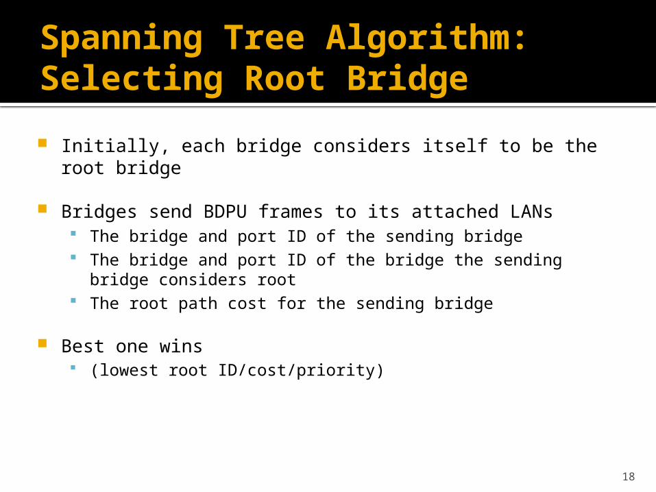
Spanning Tree Algorithm:Selecting Root Bridge
Initially, each bridge considers itself to be the root bridge
Bridges send BDPU frames to its attached LANs The bridge and port ID of the sending bridge The bridge and port ID of the bridge the sending bridge
considers root The root path cost for the sending bridge
Best one wins (lowest root ID/cost/priority)
19
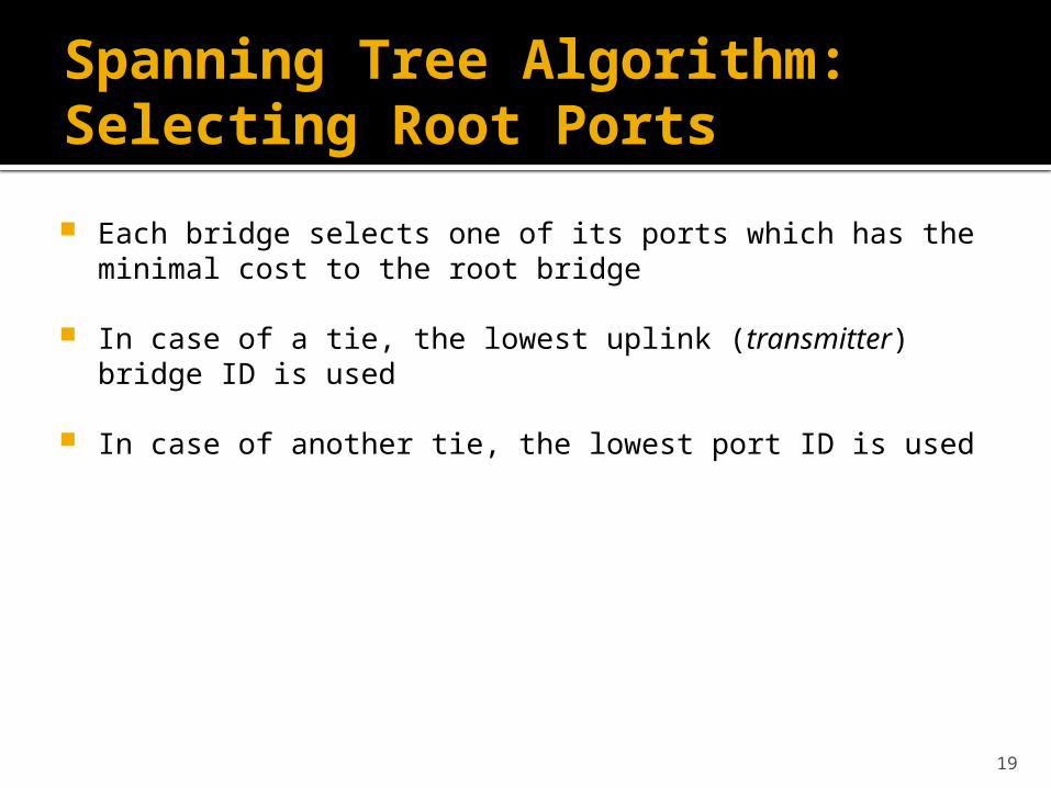
Spanning Tree Algorithm:Selecting Root Ports
Each bridge selects one of its ports which has the minimal cost to the root bridge
In case of a tie, the lowest uplink (transmitter) bridge ID is used
In case of another tie, the lowest port ID is used
20
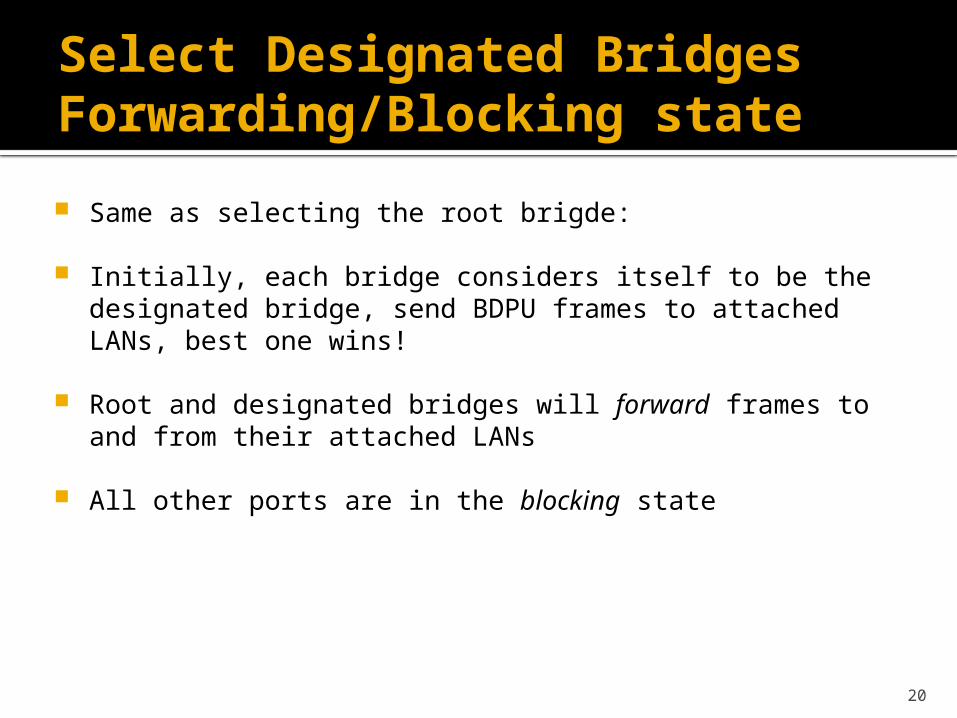
Select Designated BridgesForwarding/Blocking state
Same as selecting the root brigde:
Initially, each bridge considers itself to be the designated bridge, send BDPU frames to attached LANs, best one wins!
Root and designated bridges will forward frames to and from their attached LANs
All other ports are in the blocking state
21
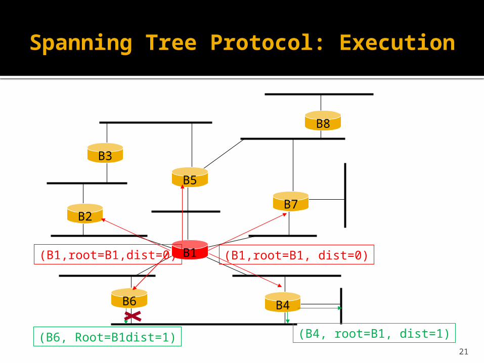
Spanning Tree Protocol: Execution
B3
B5
B7B2
B1
B6 B4
B8
(B1,root=B1, dist=0)(B1,root=B1,dist=0)
(B4, root=B1, dist=1)(B6, Root=B1dist=1)
22
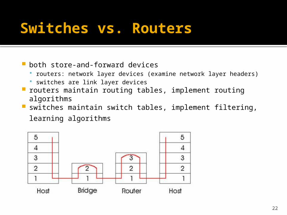
Switches vs. Routers
both store-and-forward devices routers: network layer devices (examine network layer headers) switches are link layer devices
routers maintain routing tables, implement routing algorithms
switches maintain switch tables, implement filtering,
learning algorithms
References
Parts of the slides contents are courtesy of the following people: Jim Kurose, Keith Ross: http://www.aw-bc.com/kurose_ross/ Yishay Mansour: http://www.cs.tau.ac.il/~mansour/networking-course/Icc3.ppt