UNIVERSITI TEKNIKAL MALAYSIA MELAKA - eprints.utem.edu.myeprints.utem.edu.my/18046/1/Investigation...
24
UNIVERSITI TEKNIKAL MALAYSIA MELAKA INVESTIGATION ON THE EFFECT OF MACHINING STRATEGIES ON THE SURFACE FINISH AND DIMENSIONAL ACCURACY OF FIVE-AXIS FLANK MACHINING OF CURVY ANGLED SHAPES (CONVEX) This report submitted in accordance with requirement of the Universiti Teknikal Malaysia Melaka (UTeM) for the Bachelor Degree of Engineering Technology (Process and Technology) (Hons.) by AHMAD SYAZILI BIN MD DIN B071210454 900812-02-6139 FACULTY OF ENGINEERING TECHNOLOGY 2015
Transcript of UNIVERSITI TEKNIKAL MALAYSIA MELAKA - eprints.utem.edu.myeprints.utem.edu.my/18046/1/Investigation...

UNIVERSITI TEKNIKAL MALAYSIA MELAKA
INVESTIGATION ON THE EFFECT OF MACHINING
STRATEGIES ON THE SURFACE FINISH AND DIMENSIONAL
ACCURACY OF FIVE-AXIS FLANK MACHINING OF CURVY
ANGLED SHAPES (CONVEX)
This report submitted in accordance with requirement of the Universiti Teknikal
Malaysia Melaka (UTeM) for the Bachelor Degree of Engineering Technology
(Process and Technology) (Hons.)
by
AHMAD SYAZILI BIN MD DIN
B071210454
900812-02-6139
FACULTY OF ENGINEERING TECHNOLOGY 2015

UNIVERSITI TEKNIKAL MALAYSIA MELAKA
BORANG PENGESAHAN STATUS LAPORAN PROJEK SARJANA MUDA
TAJUK: INVESTIGATION ON THE EFFECT OF MACHINING STRATEGIES ON
THE SURFACE FINISH AND DIMENSIONAL ACCURACY OF FIVE-AXIS FLANK
MACHINING OF CURVY ANGLED SHAPES (CONVEX)
SESI PENGAJIAN: 2014/15 Semester 1
Saya AHMAD SYAZILI BIN MD DIN
mengaku membenarkan Laporan PSM ini disimpan di Perpustakaan Universiti
Teknikal Malaysia Melaka (UTeM) dengan syarat-syarat kegunaan seperti berikut:
1. Laporan PSM adalah hak milik Universiti Teknikal Malaysia Melaka dan penulis. 2. Perpustakaan Universiti Teknikal Malaysia Melaka dibenarkan membuat salinan
untuk tujuan pengajian sahaja dengan izin penulis. 3. Perpustakaan dibenarkan membuat salinan laporan PSM ini sebagai bahan
pertukaran antara institusi pengajian tinggi.
4. **Sila tandakan ( )
SULIT
TERHAD
TIDAK TERHAD
(Mengandungi maklumat yang berdarjah keselamatan
atau kepentingan Malaysia sebagaimana yang termaktub
dalam AKTA RAHSIA RASMI 1972)
(Mengandungi maklumat TERHAD yang telah ditentukan
oleh organisasi/badan di mana penyelidikan dijalankan)
Alamat Tetap:
No. 129 Taman Orkid Fasa 5
08000 Sungai Petani
Kedah,
Tarikh: ________________________
Disahkan oleh:
Cop Rasmi:
Tarikh: _______________________
** Jika Laporan PSM ini SULIT atau TERHAD, sila lampirkan surat daripada pihak berkuasa/organisasi
berkenaan dengan menyatakan sekali sebab dan tempoh laporan PSM ini perlu dikelaskan sebagai
SULIT atau TERHAD.
DECLARATION
I hereby, declared this report entitled “Investigation on the Effect of Machining
Strategies on the Surface Finish and Dimensional Accuracy of Five-Axis Flank
Machining of Curvy Angled Shapes (Convex)” is the results of my own research
except as cited in references.
Signature :………………………
Name : ………………………
Date : ………………………

v
APPROVAL
This report is submitted to the Faculty of Engineering Technology of UTeM as a
partial fulfillment of the requirements for the degree of Bachelor of Engineering
Technology (Process and Technology) (Hons.). The member of the supervisory
is as follow:
……………………………….
(Project Supervisor)
vi
ABSTRACT
Machining strategist is a 3D CAM product that generates optimum roughing
and finishing CNC tool paths from the complex shapes generates by all major 3D
modelling systems. This research mainly study about the machining strategies
offered in Computer Aided Manufacturing (CAM) programming. In milling process,
there are two types of cutting strategy which are point milling and flank milling. In
this study, only the flank milling is main focused. The purpose of this research is to
find the best machining strategies namely Tanto Fan, Combin Tanto, and Combin
Parelm resulting the most accurate dimensional accuracy and surface finish. Those
three machining strategies selected were the options of tool axis given by CADCAM
software Catia. Furthermore, the simulation from Catia shows a little different and
sometimes shows same result of simulation even though users have changed the
selection of tool axis. Besides, users always confusing in selecting the most suitable
tool axis. An actual sample called End Cap was selected and it was an actual aero-
structural components. The type of raw material used was aluminium A6063. A6063
is one of the highest strength materials, commercially available alloys with fair
corrosion resistance and machinability. Typically used for aircraft skins, cowls and
structures. For analysis, Coordinate Measuring Machine and surface roughness test
was used to identify the significant effect of the factors on the response. As for the
result, the best machining strategies for the part sample based on the dimensional
accuracy was Tanto Fan. Meanwhile, the best machining strategies suitable for the
part sample based on the surface roughness was Combin Parelm. The results
obtained relied on a few conditions that have been discussed in this report. The
conditions are believed to have any chances to influence the result for this study.
There were two possible factors that contributed to the mentioned result which was
related closely to the tool trajectory and vibration during machining process.

vii
ABSTRAK
Kajian penyelidikan ini terutamanya tentang pengaturcaraan pemesinan
(proses canai) dan dikenali sebagai ‘Computer Aided Manufacturing’ (CAM)
pengaturcaraan. Dalam proses canai, amempunyai 2 jenis strategi pemotongan di
mana menggunakan titik canai dan rusuk canai. Untuk kajian ini, hanya pencanaian
rusuk akan memberi tumpuan. Tujuan kajian ini adalah untuk mencari yang
parameter paksi alat yang dinamakan ‘Tanto Fan’, ‘Combin Tanto’, dan ‘Combin
Parelm ‘memberi nilai dimensi yang paling tepat bagi sebahagian berbentuk
lengkung. 3 parameter yang berbeza adalah pilihan untuk paksi alat yang diberikan
oleh perisian CADCAM Catia. Secara teorinya, takrif bagi 3 parameter yang
diberikan oleh Catia agak umum. Tambahan pula, simulasi dari Catia menunjukkan
sedikit berbeza dan kadang-kadang menunjukkan keputusan yang sama simulasi
walaupun pengguna telah berubah pemilihan paksi alat. Tambahan pula, pengguna
akan menghadapi mengelirukan untuk memilih paksi alat yang sesuai. Nama sampel
sebenar End Cap telah dipilih. Bagi sampel bernama penutup hujung yang dipilih,
adalah salah satu komponen aeroangkasa yang sebenar. Sebab mengapa komponen
aeroangkasa dipilih kerana industri seperti aeroangkasa, di mana komponen mesti
dihasilkan dengan pasti, pada masa dan spesifikasi yang sangat tepat. Jenis bahan
mentah yang digunakan adalah aluminium A6063. A6063 adalah salah satu material
yang mempunyai kekuatan tertinggi. Kedudukan kebolehkerjaan yang rendah dan
dikimpal sahaja oleh proses rintangan. Biasanya digunakan untuk kulit pesawat,
cowls dan struktur. Untuk analisis, CMM dan kekasaran permukaan ujian telah
digunakan untuk melihat kesan yang ketara satu faktor kepada sambutan.
Berdasarkan analisis, parameter yang terbaik sesuai untuk sampel bahagian
berdasarkan ketepatan dimensi adalah Tanto Fan. Sementara itu, parameter yang
terbaik sesuai untuk sampel bahagian berdasarkan kekasaran permukaan adalah
Combin Parelm .. Hasilnya telah diperolehi oleh bergantung kepada keadaan
beberapa yang telah dibincangkan dalam karya ini. Keadaan ini dipercayai
mempunyai apa-apa peluang untuk mempengaruhi keputusan kajian ini..

viii
DEDICATIONS
I would like to dedicate to my beloved parents, Md Din bin Hasan and
Normawarti binti Ahmad because encourage me to do better in my life. Not to forget
to my brothers who are always advising me especially in moment of crisis. Last for
not list, I would like to thank for my friends and classmate because support and help
me by giving useful information and opinion during this study was performed.

ix
ACKNOWLEDGMENTS
In the name of Allah, the Compassionate, the Merciful, Praise be to Allah,
Lord of the Universe, and Peace and Prayers be upon His Prophet and Messenger.
With Grace and Blessing from Allah, I am Ahmad Syazili Bin Md Din from Faculty
of Engineering Technology have succeeded in completing my final year project
together with this thesis. First and foremost, I would like thank to Allah, because of
His willing and Blessing, I have succeeded in completing this project. High
appreciate to my supportive project supervisor, En. Syahrul Azwan Bin Sundi @
Suandi for his guidance during performing this project.
Special thanks to everybody who help me to accomplish this project. For all
helpful lecturers and technician, thank for supporting me everything regarding this
project, teaching me some new and valuable knowledge and providing me with great
equipment while conducting this experiment.
Last but not least, I would like to thank my family for trusting me and my
friends that encouraged, supported and helped me in completing this project
successfully. I am also obliged to everyone who had directly or indirectly involved
through the contributions of ideas, as well as materials and professional opinions.
x
TABLE OF CONTENTS
DECLARATION ................................................................................................................. iv
APPROVAL ........................................................................................................................... v
ABSTRACT ......................................................................................................................... vi
ABSTRAK .......................................................................................................................... vii
DEDICATIONS ................................................................................................................. viii
ACKNOWLEDGMENTS ................................................................................................... ix
TABLE OF CONTENTS ....................................................................................................... x
LIST OF FIGURES ............................................................................................................. xv
LIST OF TABLE .............................................................................................................. xvii
LIST OF SYMBOLS AND ABBREVIATIONS ............................................................ xviii
CHAPTER 1 .......................................................................................................................... 1
1.0 Introduction ............................................................................................................. 1
1.1 Problem Statement .................................................................................................. 5
1.2 Objectives ................................................................................................................ 5
1.3 Scope of Study ......................................................................................................... 6
CHAPTER 2 .......................................................................................................................... 7
2.0 Introduction ............................................................................................................. 7
2.1 Five-axis Machining ................................................................................................ 7
2.2 Machining Strategies ............................................................................................... 9
2.2.1 Tanto Fan ....................................................................................................... 10

xi
2.2.2 Combin Tanto ................................................................................................ 11
2.2.3 Combin Parelm .............................................................................................. 11
2.3 Flank Machining .................................................................................................... 12
2.4 Dimensional Accuracy .......................................................................................... 14
2.5 Surface Finish ........................................................................................................ 15
2.6 Convex Angle Surface ........................................................................................... 17
2.7 Aluminum Alloy 6063 ........................................................................................... 18
2.8 Best Fit Curve Measurement ................................................................................. 20
CHAPTER 3 ........................................................................................................................ 21
3.0 Introduction ........................................................................................................... 21
3.1 Project Planning .................................................................................................... 21
3.1.1 Phase 1 ........................................................................................................... 23
3.1.2 Phase 2 ........................................................................................................... 23
3.2 Computer Aided Design (CAD) ............................................................................ 24
3.3 Computer Aided Manufacturing (CAM) ............................................................... 26
3.3.1 Define Machine .............................................................................................. 29
3.3.2 Define Axis .................................................................................................... 30
3.3.3 Define Product ............................................................................................... 30
3.3.4 Define Part ..................................................................................................... 31
3.3.5 Define Stock ................................................................................................... 31
3.3.6 Define Tool .................................................................................................... 31
3.3.7 Manufacturing program ................................................................................. 32
3.3.8 Facing operation ............................................................................................. 33

xii
3.3.9 Roughing operation ........................................................................................ 33
3.3.10 Pocketing ........................................................................................................ 34
3.3.11 Multi-axis Flank Contouring .......................................................................... 35
3.3.11.1 Tanto Fan ................................................................................................ 35
3.3.11.2 Combin Tanto ......................................................................................... 36
3.3.11.3 Combin Parelm ....................................................................................... 37
3.3.12 Post Processor ................................................................................................ 37
3.4 Machining .............................................................................................................. 38
3.5 Measurement ......................................................................................................... 40
3.5.1 Coordinate Measuring Machine (Carl Zeiss Contura G2 RDS) .................... 40
3.5.1.1 Curve measurement ................................................................................ 41
3.5.2 Surface Roughness Measuring Tester (Mitutoyo Sj-410) .............................. 42
3.5.2.1 Surface roughness measurement ............................................................. 43
CHAPTER 4 ........................................................................................................................ 45
4.0 Introduction ........................................................................................................... 45
4.1 Dimensional accuracy Result ................................................................................ 45
4.2 Surface roughness result ........................................................................................ 49
4.3 Comparison on dimensional accuracy analysis ..................................................... 51
4.3.1 Comparison dimensional accuracy at point A ............................................... 51
4.3.2 Comparison dimensional accuracy at point B ................................................ 52
4.3.3 Comparison dimensional accuracy at point C ................................................ 53
4.3.4 Comparison dimensional accuracy at point A, point B and point C of
Tanto Fan ..................................................................................................................... 54

xiii
4.3.5 Comparison dimensional accuracy at point A, point B and point C of
Combin Tanto .............................................................................................................. 56
4.3.6 Comparison dimensional accuracy at point A, point B and point C of
Combin Parelm ............................................................................................................ 57
4.4 Comparison on surface roughness analysis ........................................................... 59
4.4.1 Comparison surface roughness at point A ..................................................... 59
4.4.2 Comparison surface roughness at point B ...................................................... 60
4.4.3 Comparison surface roughness at point C ...................................................... 61
4.4.4 Comparison surface roughness at point A, point B and point C of Tanto
Fan 62
4.4.5 Comparison surface roughness at point A, point B and point C of
Combin Tanto .............................................................................................................. 64
4.4.6 Comparison surface roughness at point A, point B and point C of
Combin Parelm ............................................................................................................ 66
4.5 Dimensional accuracy analysis of machining strategies ....................................... 68
4.6 Surface roughness analysis of machining strategies ............................................. 70
4.7 Tool wear ............................................................................................................... 72
4.8 Post processor of CNC .......................................................................................... 72
CHAPTER 5 ........................................................................................................................ 73
5.0 Introduction ........................................................................................................... 73
5.1 Dimensional analysis conclusion .......................................................................... 73
5.2 Surface roughness conclusion ............................................................................... 74
5.3 Future work ........................................................................................................... 74
APPENDIX A ...................................................................................................................... 76

xiv
REFERENCES ..................................................................................................................... 80

xv
LIST OF FIGURES
Figure 1.1: Mechanism of cutting tool in flank contouring. ........................................ 3
Figure 1.2: : Surface finish characteristics. .................................................................. 4
Figure 1.3: Differences between Concave and Convex curve shape ........................... 4
Figure 2.1: Five side machining process. ..................................................................... 8
Figure 2.2: : The cutting tool clearly shown that the tool is tangent to the drive surface at a given contact height and tool axis is the interpolation between the start and end positions. ....................................................................................................... 10
Figure 2.3: The cutting tool clearly shown that the tool is tangent to the drive surface at a given contact height and the tool axis contained in a plane normal to forward direction...................................................................................................................... 11
Figure 2.4: The cutting tool clearly shown that the tool axis is tangent to the drive surface at the specified contact height and follows the isoparametrics of the surface. .................................................................................................................................... 12
Figure 2.5: Differences between Multi-axis Flank Contouring and Flank Contouring. .................................................................................................................................... 12
Figure 2.6: Graph of ‘Ra’. .......................................................................................... 15
Figure 2.7: Graph of ‘Ry’........................................................................................... 15
Figure 2.8: Graph of ‘Rz’. .......................................................................................... 16
Figure 2.9: Example of convex angle surface machining in multi-axis flank contouring offered by CATIA V5. ............................................................................. 17
Figure 2.10: Example of convex angle surface machining in multi-axis flank contouring offered by CATIA V5. ............................................................................. 20
Figure 3.1: Flow Chart Methodology ........................................................................ 22
Figure 3.2: Flow Chart of CAD process .................................................................... 24
Figure 3.3: Location of WPC ..................................................................................... 25
Figure 3.4: Flow Chart of CAM process .................................................................... 28
Figure 3.5: Select machine type ................................................................................. 29
Figure 3.6: Selected of Reference Axis..................................................................... 30
Figure 3.7: Selected of product .................................................................................. 30
Figure 3.8: Selected of Part ........................................................................................ 31
Figure 3.9: Selected of Stock ..................................................................................... 31
Figure 3.10: Selected of tool ...................................................................................... 32
Figure 3.11:List of Manufacturing Program .............................................................. 32
Figure 3.12: Cutting tool path simultion for facing ................................................... 33
Figure 3.13: Cutting tool path simultion for roughing ............................................... 34
Figure 3.14: Cutting tool path simultion for pocketing ............................................. 34
Figure 3.15: Cutting tool path simultion for multi-axis flank contouring ................. 35
Figure 3.16: Tool axis simulation of Tanto Fan ......................................................... 36
Figure 3.17: Tool axis simulation of Combin Tanto .................................................. 36
Figure 3.18: Tool axis simulation of Combin Parelm ................................................ 37

xvi
Figure 3.19: Flow chart of post processor .................................................................. 37
Figure 3.20: Deckel Maho DMU 60 Monoblock ....................................................... 39
Figure 3.21: Multi-axis flank contouring machining process .................................... 40
Figure 3.22: Zeiss Coordinate Measuring Machine ................................................... 40
Figure 3.23: The location of base alignment on sample ............................................ 42
Figure 3.24: The probing process for the sample. ...................................................... 42
Figure 3.25: Roughness tester Mitutoyo SJ-410. ....................................................... 43
Figure 3.26: . Detector stylus was parallel to the measured surface .......................... 44
Figure 3.27:Examples of surface roughness reading. ................................................ 44
Figure 4.1: Point taken for the dimensional analysis on the machining flank. .......... 46
Figure 4.2: Start and end point of the probing process. ............................................. 46
Figure 4.3: CMM Measurement result of Tanto Fan at position A. .......................... 47
Figure 4.4: CMM Measurement result of Combin Tanto at position A..................... 47
Figure 4.5: CMM Measurement result of Combin Parelm at position A................... 47
Figure 4.6: Point taken for the Surface roughness analysis on the machining flank. 49
Figure 4.7: Chart of dimensional accuracy at point A ............................................... 51
Figure 4.8: Chart of dimensional accuracy at point B. .............................................. 52
Figure 4.9: Chart of dimensional accuracy at point C ............................................... 53
Figure 4.10: Chart of dimensional accuracy at point A, point B and point C of Tanto Fan .............................................................................................................................. 54
Figure 4.11: Chart of the Mean of sigma value at all point for Tanto Fan ................ 55
Figure 4.12: Chart of dimensional accuracy at point A, point B and point C of Combin Tanto ............................................................................................................ 56
Figure 4.13: Chart of the Mean of sigma value at all point for Combin Tanto ......... 57
Figure 4.14: Chart of dimensional accuracy at point A, point B and point C of Combin Parelm .......................................................................................................... 58
Figure 4.15: Chart of the Mean of sigma value at all point for Combin Parelm ....... 58
Figure 4.16: Chart of surface roughness at point A ................................................... 60
Figure 4.17: Chart of surface roughness at point B ................................................... 61
Figure 4.18: Chart of surface roughness at point C ................................................... 62
Figure 4.19: Chart of surface roughness at point A, point B and point C of Tanto Fan .................................................................................................................................... 63
Figure 4.20: Chart of the mean ‘Ra’ value at all point for Tanto Fan........................ 64
Figure 4.21: Chart of surface roughness at point A, point B and point C of Combin Tanto .......................................................................................................................... 65
Figure 4.22: Chart of the mean ‘Ra’ value at all point for Combin Tanto ................. 65
Figure 4.23: Chart of surface roughness at point A, point B and point C of Combin Parelm ........................................................................................................................ 66
Figure 4.24: Chart of the mean ‘Ra’ value at all point for Combin Parelm ............... 67
Figure 4.25: Chart of mean sigma value at all points in all machining strategies ..... 68
Figure 4.26: Chart of mean sigma value at all points in all machining strategies ..... 70

xvii
LIST OF TABLE
Table 2.1: Comparison between composition of aluminium alloy 6000 series and 7000 series. ................................................................................................................. 18
Table 3.1: Deckel Maho DMU 60 Monoblock specifications. .................................. 38
Table 3.2: Zeiss Coordinate Measuring Machine specifications ............................... 41
Table 4.1: Actual measurement result of Tanto Fan at all position. .......................... 48
Table 4.2: Actual measurement result of Combin Tanto at all position .................... 48
Table 4.3: Actual measurement result of Combin Parelm at all position. ................. 48
Table 4.4: Actual surface roughness result of Tanto Fan at all position .................... 49
Table 4.5: Actual surface roughness result of Combin Tanto at all position. ............ 50
Table 4.6: Actual surface roughness result of Combin Parelm at all position. .......... 50
Table 4.7: Ranking of the best machining strategies by dimensional accuracy ......... 68
Table 4.8: Ranking of the best machining strategies by surface roughness............... 70
xviii
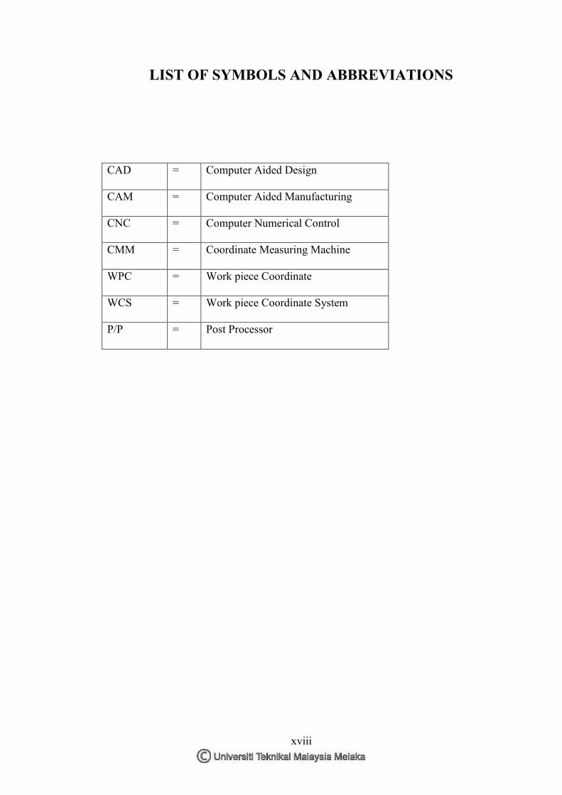
LIST OF SYMBOLS AND ABBREVIATIONS
CAD = Computer Aided Design
CAM = Computer Aided Manufacturing
CNC = Computer Numerical Control
CMM = Coordinate Measuring Machine
WPC = Work piece Coordinate
WCS = Work piece Coordinate System
P/P = Post Processor
1
CHAPTER 1 INTRODUCTION
1.0 Introduction
The purpose of this research is to investigate the effect of machining strategies
that are offered by CATIA V5 as the CAD/CAM software which will be used. Tanto
Fan, Combin Tanto, and Combin Parallelism are the strategies that going to be
applied. Each option of machining strategy used is expected to give different results
of machining process in term of surface finish and dimensional accuracy. In addition,
this research also emphasize to actual part because of the typical problem that the
industry faced is necessary to do several test cutting in order to release a product that
satisfy the customer specifications.
5-axis CNC machining has been commonly used in manufacturing of complex
geometries in automobile, aerospace, energy, and mould industries. This advanced
machining operation provides better shaping capability and higher productivity
compared to traditional 3-axis machining. 5-axis machining provides infinite
possibilities as to the part sizes and shapes can effectively process. The term “5-axis”
refers to the number of directions in which the cutting tool can move. On a 5-axis
machining centre, the cutting tool moves across the X, Y and Z linear axes as well as
rotates on the A and B axis to approach the workpiece from any direction. In other
words, five sides of a part can be processed in a single setup. Nevertheless,
manufacturing of complex workpieces is still difficult, although the 5-axis machining
proposes a lot of new possibilities and advantages (López, 2005). In addition, the
geometrical accuracy of 5-axis machine tools is also an important factor.
Machining strategist is a 3D CAM product that generates optimum roughing
and finishing CNC tool paths from the complex shapes generates by all major 3D
modelling systems. Machining strategist is a technological leader in this area with
many unique machining strategies for generating world-class machining programs.

2
At the same time, many of these strategies can improve the productivity of older
CNC machines with dramatically reduced air cutting time and programs with smooth
arcs which help to maintain continuous machine tool motion. Machining strategist
can take the machining capabilities to new levels and productivity to new heights.
Machining strategist has been developed to be very easy to learn and use. Machining
strategist includes, Z-level Roughing, Horizontal Finish Machining, Fixed axis and
few other strategist.
The 5-axis machining operation contains two different milling methods: end
milling and flank milling. The cutting edges near the end of a cutter perform the
actual material removal in end milling while the circumferential part of a cutter
mainly does the cutting in flank milling. Compared with point milling, flank milling
has its unique advantages. It can increase the material removal rate, lower the cutting
forces, eliminate necessary hand finish, ensure improved component accuracy and
result in longer tool life. Thus, it offers a good choice for machining slender parts,
like turbine blades and impellers. Recently, increasing attention was drawn into the
problem of optimum positioning of the cutter for flank milling. The mechanism of
this multi axis flank contouring is it uses the cutting tool body for mill the part. This
requires an accurate computation of the tool orientation. Flank milling is therefore
very interesting for the machining of developable surfaces, because this method is
able to machine the surface accurately with a high level of productivity. By using
flank milling or side milling techniques, the machined surface quality can be
improved compared with using end milling techniques. Sometimes, the machined
parts do not need a polishing process after flank milling and the machining efficiency
can be improved a lot. The figure 1.1 shows the mechanism of cutting tool in flank
contouring.

3
Figure 1.1: Mechanism of cutting tool in flank contouring. (Chi-Lung Kuo., 2015)
The finish machining work piece will undergo the dimensional and surface
finish analysis process. Two types of accuracy in manufacturing can be distinguished
which is dimensional accuracy and shape accuracy. Dimensional accuracy is
achieved when the final product falls within the tolerance bands for each dimension
specified on the drawings. Increasing demand for performance designs todays,
aerospace components having complex geometries and surfaces are required to be
manufactured in tight tolerances. Thus, in this research the products will be
undergoing the dimensional accuracy test by using a CMM machine. The testing will
be done by comparing the dimensional accuracy between Combin Tanto, Tanto Fan,
and Combin Parelm sample.
Surface finish or also known as surface texture or surface topography is the
nature of a surface as defined by the 3 characteristic which is surface roughness,
waviness and lay. Surface roughness commonly shortened to roughness, is a measure
of the finely spaced surface irregularities. In engineering, this is what is usually
meant by "surface finish". Meanwhile, lay is the direction of the predominant surface
pattern ordinarily determined by the production method used. Lastly, waviness is the
measure of surface irregularities with spacing greater than that of surface roughness.
These usually occur due to warping, vibrations, or deflection during machining.
Cutting tool
Work piece

4
Figure 1.2: : Surface finish characteristics.
T.V, V. (1990)
There are two classes of polygons, which is convex and concave. In a convex
polygon, no diagonal goes outside the figure as it travels from one corner to the
other. Another property of convex polygons is that no angle inside the polygon will
have a measure greater than 180 degrees. Meanwhile, Concave curve describes and
inward curve while convex curve in opposites means a curve that bulges outward.
They are used to describe gentle, subtle curves like the kinds found in mirrors or
lenses. In mathematics, a convex function is the positive of a concave function. A
convex function is also synonymously called convex downward, convex down,
concave upwards, concave cap or upper concave.
Figure 1.3: Differences between Concave and Convex curve shape

5
1.1 Problem Statement
Nowadays, products designed in aerospace industries are becoming more and
more complex and complicated to meet the increasing demand of customers. Due to
strong requirement from this industry, this research is utilized 5-Axis machining
which offers several advantages over the traditional 3-axis machining in producing
complex shape surfaces, reduces the machining time and improves the surface finish.
Most work so far has focused on point milling with end-milling of doubly
curved surfaces. While much attention has been focused on machining with the
bottom end of cutters (D. Dragomatz, 1997), less research has been done on a flank
milling, which can provide large productivity gains for such class of surfaces as are
found in blades, fans, turbines and other engineering objects (J.-M. Redonnet, 1998).
Rather than milling with the tip of the tool, flank milling cuts with the shaft of the
tool, removing greater amounts of material in a single pass. Flank milling is useful
for machining objects such as impellers, blisks, and turbine blades, where accuracy is
important. With flank milling the surface can be cut with a single pass, which is more
efficient than point milling methods.
Next, common industry needs to do several test cuts in order to produce good
finished product. The reason is the industry need to determine the best parameters
such as tool axis for flank milling. The tool axis option named Combin Tanto, Tanto
Fan, and Combin Parelm has a small contrast between each other. This small contrast
between tool axis confusing the programmer to match the flank shape with the tool
axis options. Moreover, this will lead to high production cost and take several times.
Therefore, it is essential to study on machining strategies for flank contouring in
order to know exactly the most suitable strategy for flank contouring parts.
1.2 Objectives
The objectives of this research are as follows:

6
(a) To investigate the effect on surface finish and dimensional accuracy based on
machining strategies.
(b) To study the surface machining strategies (Tanto Fan, Combined Tanto, and
Combined Parallelism) in producing flank shape.
(c) To make recommendations on the best machining strategy for flank at convex
curve shape.
1.3 Scope of Study
This study started with the finding of actual CAD model that require convex
shapes of flank contouring machining. The 3D part model was gained from the
internet sources or actual industrial relationship (IP). Nevertheless, the 3D part model
was doing some adjustment and modification on the part because this research was
only focusing on flank contouring machining. Computer aided manufacturing
(CAM) was involved in this research by using CADCAM software named Catia V5
because flank contouring was an option in CAM. This research was concentrated on
three types of machining strategies which were Combin Tanto, Tanto Fan, and
Combin Parallelism. The parameters such as depth of cut, spindle speed and feed rate
were remained constant in this study. An Aluminum A6063 was identified to be used
in physical machining. Then, 5-axis CNC machine was performed the machining
process based on the completed part program. Two different types of analysis were
tested. The first one, the part was undergo Surface Finish tested using Mitutoyo Surf
Test Machine which was focused in surface roughness. The measurement of
dimensional accuracy was done by using Coordinate Measuring Machine (CMM).
Curve measurement was proceeded in order to inspect the dimension of the part. The
part model dimension was the reference to compare with the finish product. At this
point, an analysis was made according to the objectives of this research. Besides that,
the evaluation of this research was based on the final result after doing machining.
This is because this research concentrating on the finish product. Lastly, the report
was published for further reference or improvement in the future.
7
CHAPTER 2 LITERATURE REVIEW
2.0 Introduction
Literature review discussed the relevant topics and a guide for studies. This
section will give part in order to get more information about machining strategies of
multi-axis flank contouring and will give idea how the flank machining worked. At
an early stage of the studies, some gap analysis has been carried out in order to
ensure the relevance of this research. Reference books, research journals and online
conference article were the main source in the thesis guides. This section will include
the principle of 5-axis machining, flank machining, machining strategies,
dimensional accuracy, surface finish, convex angle shape and Aluminum 6063.
2.1 Five-axis Machining
Five-axis machining has received much attention in both industry as well as
the academic community since the early 90’s. It provides a number of advantages
over traditional three-axis machining, such as higher production rate and fewer
setups, thus it is most suitable to the production of complex geometries like turbine
blade, impeller, and other high value products. A 5-axis machine gives the cutting
tool access to most features of a part without changing the machine setup, as shown
in Fig. 2.1. This is commonly known as 5-sided machining (Vickers, 1989). For
example, a 5-axis machine can drill holes in the sides of a part by simply rotating the
part. This eliminates specialized.