UNIVERSITI TEKNIKAL MALAYSIA MELAKAeprints.utem.edu.my/15600/1/DESIGN ANALYSIS OF A... ·...
24
UNIVERSITI TEKNIKAL MALAYSIA MELAKA UNIVERSITI TEKNIKAL MALAYSIA MELAKA DESIGN ANALYSIS OF A VACUUM CLEANER USING DFMA (BOOTHROYD-DEWHURST) METHOD This report submitted in accordance with requirement of the Universiti Teknikal Malaysia Melaka (UTeM) for the Bachelor's Degree in Manufacturing Engineering Technology (Product Design) with Hons by SITI NUR HUMAIRA BINTI MAZLAN B071110343 920225-04-5392 FACULTY OF E NGINEERING TECHNOLOGY 2015 © Universiti Teknikal Malaysia Melaka
Transcript of UNIVERSITI TEKNIKAL MALAYSIA MELAKAeprints.utem.edu.my/15600/1/DESIGN ANALYSIS OF A... ·...

UNIVERSITI TEKNIKAL MALAYSIA MELAKA
UNIVERSITI TEKNIKAL MALAYSIA MELAKA
DESIGN ANALYSIS OF A VACUUM CLEANER USING DFMA
(BOOTHROYD-DEWHURST) METHOD
This report submitted in accordance with requirement of the Universiti Teknikal
Malaysia Melaka (UTeM) for the Bachelor' s Degree in Manufacturing Engineering
Technology (Product Design) with Hons
by
SITI NUR HUMAIRA BINTI MAZLAN
B071110343
920225-04-5392
FACULTY OF ENGINEERING TECHNOLOGY
2015
© Universiti Teknikal Malaysia Melaka
UNrvERSm TEKMKAJ.. lilAl..AYSIA ME.LN<A UNIVERSITI TEKNIKAL MALAYSIA
BORANG PENGESAHAN STATUS LAPORAN PROJEK SARJANA MUDA
TAJUK: Design Analysis of A Vacuum Cleaner Using DFMA (Boothroyd-Dewhurst) Method
SESI PENGAJIAN: 2014/15 Semester 1
Saya SITI NUR HUMAIRA BINTI MAZLAN
mengaku membenarkan Laporan PSM ini disimpan di Perpustakaan Universiti Teknikal Malaysia Melaka (UTeM) dengan syarat-syarat kegunaan seperti berikut:
1. Laporan PSM adalah hak milik Universiti Teknikal Malaysia Melaka dan penulis. 2. Perpustakaan Universiti Teknikal Malaysia Melaka dibenarkan membuat salinan
untuk tujuan pengajian sahaja dengan izin penulis. 3. Perpustakaan dibenarkan membuat salinan laporan PSM ini sebagai bahan
pertukaran antara institusi pengajian tinggi. 4. **Sila tandakan ( ./)
D SULIT (Mengandungi maklumat yang berdarjah keselamatan atau kepentingan Malaysia sebagaimana yang termaktub dalam AKTA RAHSIA RASMI 1972)
D TERHAD (Mengandungi maklumat TERHAD yang telah ditentukan oleh organisasi/badan di mana penyelidikan dijalankan)
[2f TIDAK TERHAD
Disahkan oleh:
~~ ~ Alamat Tetap:
Lot 1796-2, Jalan Tambak Bugis,
75460 Telok Mas,
Melaka.
Tarikh: 30 January 2015 Tarikh: __ '2._~__,/,_____...1 (_U>_l S __ _
- Jika Laporan PSM ini SULIT atau TERHAD, sila larnpirkan surat daripada pihak berkuasa/organisasi berkenaan dengan rnenyatakan sekali sebab dan ternpoh laporan PSM ini perlu dikelaskan sebagai SULIT atau TERHAD.
© Universiti Teknikal Malaysia Melaka
DECLARATION
I hereby, declared this report entitled "Design Analysis of A Vacuum Cleaner
Using DFMA (Boothroyd-Dewhurst) Method" is the results of my own research
except as cited in references.
Signature
Author' s Name
Date
~" rlh,J (./!: ... ·~················ ·· ·········
Si ti Nur Humaira Binti Mazlan
30 January 2015
© Universiti Teknikal Malaysia Melaka

APPROVAL
This report is submitted to the Faculty of Engineering Technology ofUTeM as a
partial fulfillment of the requirements for the degree of Bachelor' s Degree in
Manufacturing Engineering Technology (Product Design) with (Hons). The
member of the supervisory is as follow:
(Project Supervisor)
90HD FA'IZ 9fN WAHID "•nsyatah
.i.ui.. TelNIDgl Keiuruteraan ~ F akulli TeknOIOgo Ke1uM11r11an
Unrvefsiti Tel(nrl<al Malaysia~
© Universiti Teknikal Malaysia Melaka

DEDICATION
To my beloved parents thankyou for your continuos support from the beginning until
I managed to finish my Final Year Project. Thankyou for all the sacrifice and
supports that both of you gives and your strength makes me stand further to achieve
my dreams. Thankyou very much.
© Universiti Teknikal Malaysia Melaka ill
Abstrak
Abstract
Dedication
Acknowledgment
Table of Content
List of Tables
List of Figures
TABLE OF CONTENT
List Abbreviations, Symbols and Nomenclatures
CHAPTER 1 : INTRODUCTION
1.1 General Introduction
1.2 Problem statement
1.3 Objectives
1. 4 Scope of study
CHAPTER 2 : LITERATURE REVIEW
2.1 Design for manufacturing and assembly
2.2 Design for assembly
2.2.1 Design for Assembly (DFA) Guidelines
2.3 Design for manufacturing
2.3 .1 DFM guidelines
2.4 DFMA approaches
2.4.1 Boothroyd-dewhurst method
2.4.2 Lucas-hull method
2.4.3 Hitachi evaluation method
2.4.4 DFMA guidelines
2.5 Vacuum cleaner
2. 5 .1 Hi story of vacuum cleaner
2.5.2 Types of vacuum cleaner
© Universiti Teknikal Malaysia Melaka
11
Ill
IV
v
Vilt
IX
XI
1
1
2
2
3
4
4
7
9
10
11
12
13
17
18
19
19
19
20
v

ACKNOWLEDGEMENT
Foremost, I would like to express my sincere gratitude to my supervisor, En Fai’z bin
Mohd Wahid for the continuos support of my Final Year Project study and research, for
his patience, motivation,enthusiasm and immense knowledge. His guidance helped me in
all time of research and writing of this thesis. I am lucky to have him as my supervisor.
Besides my supervisor, I would like to thank my friends and classmate for the continuos
support for me. I would never be able to finish my thesis without the guidance of my
supervisor, help from friends, and support from my family.
I acknowledge my sincere indebtedness and gratitude to my parents for their love, dream
and sacrifice throughout my life. I am really thankful for what their did to raise me up.
Their patience is my strength for me to study more harder to achieve my dreams. I could
not find the appropriate words to describe my appreciation for their devotion, support and
faith in my ability to achieve my dreams.
Lastly, I would like to thank anybody that contributes and helps me in my final year
project directly or indirectly. I would like to acknowledge their comments and suggestion,
which was crucial for the successful completion of this study.

i
ABSTRACT
Design for manufacturing and assembly (DFMA) methodology are being implemented to
analyze the house appliances (vacuum cleaner) in the aspects of assembly, handling and
insertion, part of the assembly and manufacturing process. The problems identified for
this vacuum cleaner are there are too many parts of the vacuum cleaner. Also, there are
too many difficulties involved in an assembly process. The objectives of this project are to
reduce part while maintaining the function of a vacuum cleaner, to increase the DFA
index of the vacuum cleaner 3 in 1, to draw the new design after the analysis, to reduce
manufacturing cost for the vacuum cleaner and reduce the assembly time. The study has
proven to save assembly time by 282.53 s, which is 42% more efficient than the original
design. Besides the total cost per product for manufacturing has saved 2.80 $. The
number of parts is also reduced from 87 parts to 40. The DFA index is improved from 4.2
to 10.0 too. The study result has revealed the DFMA methodology benefits of the final
product (vacuum cleaner 3 in 1).

ii
ABSTRAK
Reka bentuk untuk proses dan pemasangan adalah satu kaedah yang digunakan untuk
menganalisa alatan barangan rumah dalam aspek kesusahan semasa pemasangan dan
pengendalian. Masalah yang didapati terhadap pembersih habuk ini adalah terlalu
banyak bahagian yang perlu dipasang dan diproses. Objektif projek ini adalah untuk
mengurangkan masa pemasangan, mengurangkan kos pemasangan untuk pekerja,
meningkatkan indeks DFA untuk produk ini, dan untuk mencadangkan reka bentuk
yang baru untuk pembesih habuk. Melalui kajian yang telah dibuat, terbukti dengan
menggunakan kaedah ini, kos pemsangan dapat dikurangkan sebanyak 282.53 s, 48.5%
lebih bagus daripada yang sebelumnya. Kos untuk satu bahagian juga dapat
dikurangkan sebanyak $2.08. Bilangan bahagian juga dapat dikurangkan daripda 80
bilangan sehingga ke 40 bilangan sahaja. Indeks DFA juga meningkat daripda 4.2
sehingga 10.

iii
TABLE OF CONTENT
Abstrak i
Abstract ii
Table of content iii
List of table vi
List of figures vii
List of Abbreviations, Symbols and Nomenclatures viii
CHAPTER 1 : INTRODUCTION 1
1.1 General Introduction 1
1.2 Problem statement 2
1.3 Objectives 2
1.4 Scope of study 3
CHAPTER 2 : LITERATURE REVIEW 4
2.1 Design for manufacturing and assembly 4
2.2 Design for assembly 6
2.3 Design for manufacturing 10
2.3.1 DFM guidelines 10
2.4 DFMA approaches 12
2.4.1 Boothroyd-dewhurst method 12
2.4.2 Lucas-hull method 16
2.4.3 Hitachi evaluation method 17
2.4.4 DFMA guidelines 18
2.5 Vacuum cleaner 19
2.5.1 History of vacuum cleaner 19
2.5.2 Types of vacuum cleaner 20
2.5.3 3 in 1 vacuum cleaner 23
2.6 Manufacturing process of vacuum cleaner 24
2.6.1 Raw material 24
2.6.2 Injection molding process 24
2.7 Case study : DFMA and CE in white goods 25
2.7.1 Which technology? 25
iv
2.7.2 The substituted assembly 26
2.7.3 Discussion and conclusion 29
CHAPTER 3 : RESEARCH METHODOLOGY 30
3.1 Flow chart 31
3.2 Formulation 31
3.3 Literature review 31
3.4 Identify the parts of vacuum cleaner 31
3.5 Using DFMAmethod as solver 31
3.6 Purpose new design 33
CHAPTER 4 : RESULTAND DISCUSSIONS 34
4.1 Vacuum cleaner information 34
4.2 Bill of materials 35
4.3 Existing design for vacuum cleaner 3 in 1 36
4.3.1 Existing design for vacuum cleaner 37
4.3.2 Structure chart of the assembly sequences 39
4.3.3 Design for analysis for old design 41
4.3.4 DFM analysis foe old design 46
4.3.5 Suggestion for redesign vacuum cleaner 49
4.4 Improved design 51
4.4.1 Exploded view for new design 52
4.4.2 Bill of materials 53
4.4 3 Structure chart for new design 55
4.4.4 DFA analysis of a new design 56
4.4.5 DFM analysis for new design 59
4.5 DFMA analysis and discussions 61
4.5.1 Design comparisons 63
4.5.2 Research limitations 65

v
CHAPTER 5 : CONCLUSIONAND RECOMMENDATIONS 66
5.1 Conclusion 66
5.2 Recommendation for further works 67
REFERENCES 68
APPENDICES
vi
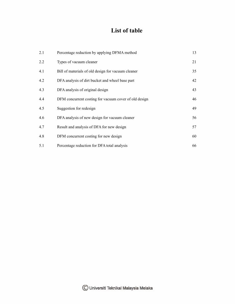
List of table
2.1 Percentage reduction by applying DFMAmethod 13
2.2 Types of vacuum cleaner 21
4.1 Bill of materials of old design for vacuum cleaner 35
4.2 DFA analysis of dirt bucket and wheel base part 42
4.3 DFA analysis of original design 43
4.4 DFM concurrent costing for vacuum cover of old design 46
4.5 Suggestion for redesign 49
4.6 DFA analysis of new design for vacuum cleaner 56
4.7 Result and analysis of DFA for new design 57
4.8 DFM concurrent costing for new design 60
5.1 Percentage reduction for DFA total analysis 66
vii
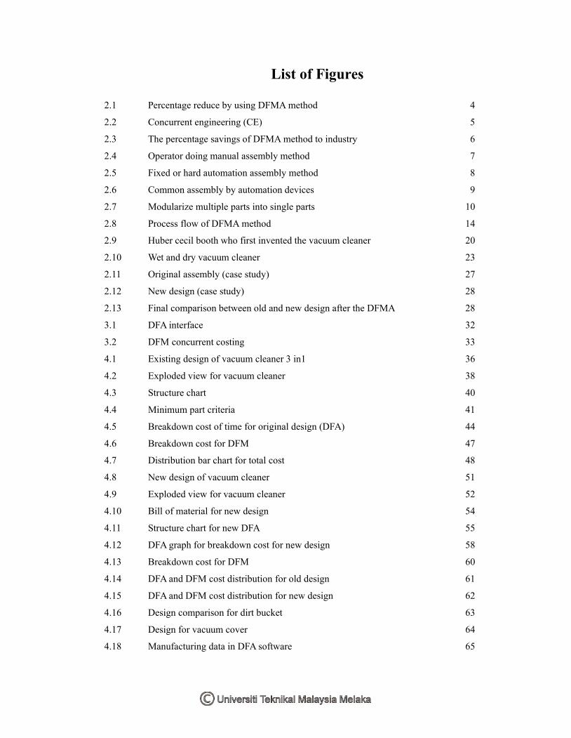
List of Figures
2.1 Percentage reduce by using DFMAmethod 4
2.2 Concurrent engineering (CE) 5
2.3 The percentage savings of DFMAmethod to industry 6
2.4 Operator doing manual assembly method 7
2.5 Fixed or hard automation assembly method 8
2.6 Common assembly by automation devices 9
2.7 Modularize multiple parts into single parts 10
2.8 Process flow of DFMAmethod 14
2.9 Huber cecil booth who first invented the vacuum cleaner 20
2.10 Wet and dry vacuum cleaner 23
2.11 Original assembly (case study) 27
2.12 New design (case study) 28
2.13 Final comparison between old and new design after the DFMA 28
3.1 DFA interface 32
3.2 DFM concurrent costing 33
4.1 Existing design of vacuum cleaner 3 in1 36
4.2 Exploded view for vacuum cleaner 38
4.3 Structure chart 40
4.4 Minimum part criteria 41
4.5 Breakdown cost of time for original design (DFA) 44
4.6 Breakdown cost for DFM 47
4.7 Distribution bar chart for total cost 48
4.8 New design of vacuum cleaner 51
4.9 Exploded view for vacuum cleaner 52
4.10 Bill of material for new design 54
4.11 Structure chart for new DFA 55
4.12 DFA graph for breakdown cost for new design 58
4.13 Breakdown cost for DFM 60
4.14 DFA and DFM cost distribution for old design 61
4.15 DFA and DFM cost distribution for new design 62
4.16 Design comparison for dirt bucket 63
4.17 Design for vacuum cover 64
4.18 Manufacturing data in DFA software 65

viii
List Abbreviations, Symbols and Nomenclatures
DFMA Design for manufacturing and assembly
DFA Design for assembly
DFM Design for manufacturing
CE Concurrent engineering
AEM Assembly evaluation method
E Assembly evaluation score ratio
K Assembly cost ratio
A The number of essential components
B The number of non-essential components
tm Total assembly labor time
Nmin Number of minimum part

ix
1
CHAPTER 1
INTRODUCTION
1.1 General Introduction
The recent developments in design for manufacturing and assembly, the need for improving
quality and reducing the manufacturing, we need a more structured and flexible design
approaches. This can be done or achieved by using software called as DFMA. Design for
Manufacturing and Assembly (DFMA) is an approach to design that focuses on ease of
manufacture and efficiency of the assembly. It is a well-established approach in sectors such as
the automotive and consumer products industries that are driven by the need to produce large
numbers of consistently high-quality products efficiently. For this project, a 3 in 1 vacuum
cleaner was modeled using the software, Solid works and all the data was imported to DFMA.
DFMA analysis was performed and computes all the essential requirements and the most
optimal design can be achieved throughout the analysis.
Much of the early research work on Design for Manufacturing and Assembly (DFMA) was
done in the early 1970 by Boothroyd Dewhurst. Boothroyd Dewhurst and team were studied
many of the component and came out with the idea of composing a systematic methodology.
The main objective for this system is to relate to the Product design, Assembly operation and
Assembly method in details. Others than Boothroyd, they are the company that works
similarly with this concept called as The Hitachi Evaluation Method that was developed at
Hitachi in Japan. The basic idea for the reduction of cost by simplification of its design
includes:
2
a) Reduction of number of components
b) Ensuring that the parts are easy to assemble
c) Increasing the use of standardized parts across entire product range.
d) Designing with widest possible tolerance
e) Material selection must be considered manufacturing, not just function.
1.2 Problem Statement
In developing this project, there are several problems that need to be concerned. This project
has involved the house appliance that is vacuum cleaner. Design for manufacturing and
assembly (DFMA) methodology are being implemented to analyze the vacuum cleaner in the
aspects of assembly, handling and insertion, part of the assembly and manufacturing process.
The problems identified for this vacuum cleaner are there is too many parts of the vacuum
cleaner and time to assemble the parts are higher. Also, there is the existing design has more
part complexity of the manufacturing process. So,with the application of the Design for
Manufacturing and Assembly (DFMA) methodology is expected to solve the problem in order
to lower the cost of manufacturing and to ease the process of assembly.
1.3 Objective
The main objective of this project is to analyze the design of a vacuum cleaner by using
DFMA (Boothroyd- Dewhurst) method. Besides, the other specific objectives are:
1. To reduce part while maintaining the function of a vacuum cleaner
2. To increase the DFA index of the vacuum cleaner 3 in 1
3. To draw the new design after the analysis
4. To reduce manufacturing costs for the vacuum cleaner
5. To reduce total assembly time for the assembly process.
3
1.4 Scope of study
This project will involve the consumer product for house appliances. The product that has
been chosen is vacuum cleaner.The project will be focusing on how DFMA method plays an
important role and how it works for reducing the part for product, reducing the manufacturing
cost, reducing the labor cost, making the manufacturing process easier and simplify the
manufacturing process. The scope of study are:
1. Using software DFMA name Boothroyd Dewhurst method
2. Focusing on 3 major sub-assembly (vacuum cover sub-assembly, dirt bucket sub-assembly,
hard floor nozzle assembly)
3. Using a multipurpose vacuum cleaner (3 in 1 vacuum cleaner)
4. Focusing on mechanical parts only.
4
CHAPTER 2
LITERATURE REVIEW
2.1 Design for manufacturing and assembly (DFMA)
DFMA can be drawn from an industry point of view as a system by which ways of efficient
manufacture and configuration of smaller parts are planned and made possible for their use in
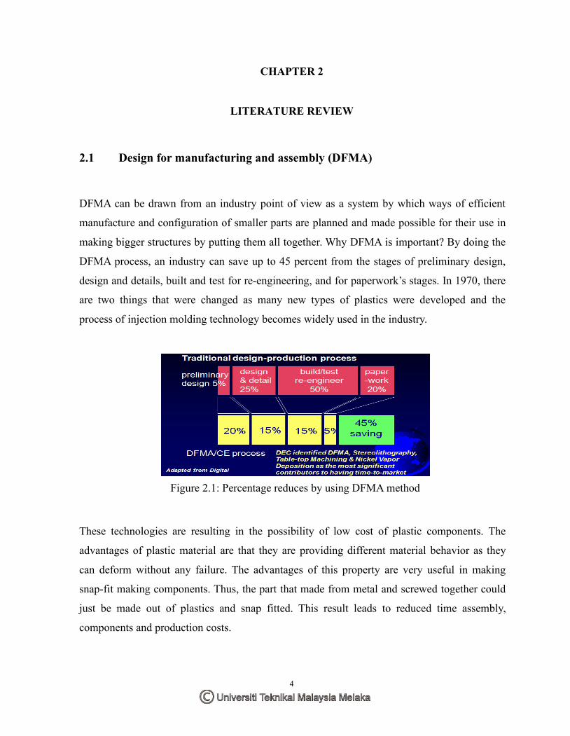
making bigger structures by putting them all together. Why DFMA is important? By doing the
DFMA process, an industry can save up to 45 percent from the stages of preliminary design,
design and details, built and test for re-engineering, and for paperwork’s stages. In 1970, there
are two things that were changed as many new types of plastics were developed and the
process of injection molding technology becomes widely used in the industry.
Figure 2.1: Percentage reduces by using DFMAmethod
These technologies are resulting in the possibility of low cost of plastic components. The
advantages of plastic material are that they are providing different material behavior as they
can deform without any failure. The advantages of this property are very useful in making
snap-fit making components. Thus, the part that made from metal and screwed together could
just be made out of plastics and snap fitted. This result leads to reduced time assembly,
components and production costs.

5
Several companies were trying to bring their product faster to the market. This could not be
done successfully because there might be changes in the design by the manufacturing
engineering and product development was held up. This will hold up waiting the engineer
change to be approved by the designer. This process often delays as the designer might be
busy doing other works. The concurrent engineering (CE) was being introduced and became
popular to simplify the problems.
Concurrent engineering (CE) is the combination of the team of an engineer and management
that would be assigned to each new product. This team may consist of different background of
the members from any department related including mechanical designer, electrical engineers,
software engineers, production engineers, marketing and sales, and management. The
production will give the feedback as the design was generated. The sales people would
negotiate of product outlook and features. The biggest advantages of the CE was that the
product was designed in the way that the manufacturing cost and time will be low in
production.
Figure 2.2 : ConcurrentEngineering (CE)
Boothroyd and the team were analyzed over hundreds of products and suggested the design
improvements for manufacturing and assembly ease. They developed a very large guideline on
the design,estimation whether the design was designed well in manufacturing point of view
and the potential methods to improve the design. The idea of Design for Manufacturing (DFM)
and Design for Assembly (DFA) in subsequent years were extended to include design for the
environment and design for maintenance. The basic idea for the reduction cost of a product

6
through simplification of its design. It can achieve by the reduced number of components,
parts that are easy to assemble, use standard parts, designing widest possible tolerance and
material selection must be considered for manufacturing also, not just function.
Figure 2.3 : The percentage savings of DFMAmethod to industry
2. 2 Design forAssembly ( DFA)
The aim of design for assembly (DFA) is to simplify the product so that the assembly process
can be reduced. DFA notice the need to analyze both of the part design and the whole product
for any assembly problem early in the design process. DFA also defined as a process for
improving the product for easy and low cost assembly and it is focused on functionality and
concurrent assembly. By applying DFA, it is not about the reducing part, also its include the
improvement of quality and reliability. Many companies have been essentially doing DFA for
a long time. Top companies are applying DFA in their product to achieve 3 main goals :
a) Improve their products while reducing cost.
b) Increase competitive advantage.
c) Hold suppliers accountable.
7
The Boothroyd-Dewhurst method includes the preliminary design, selection of assembly
method and design or redesign of product for the selected method. The selection for the best
method of DFMA must be done early in the stages of the design process. The assembly
method consist of three types that are widely used in the industry. The types are manual
assembly, robotic assembly and fixed and hard automation assembly. For manual assembly,
the volume to produce are less than 1000 parts per year. Fixed or hard automation needs the
high volume that is more than million parts per year while for somewhere in between these
limits, and based on some other considerations either for labor cost and technical requirements,
robotic assembly may be optional.
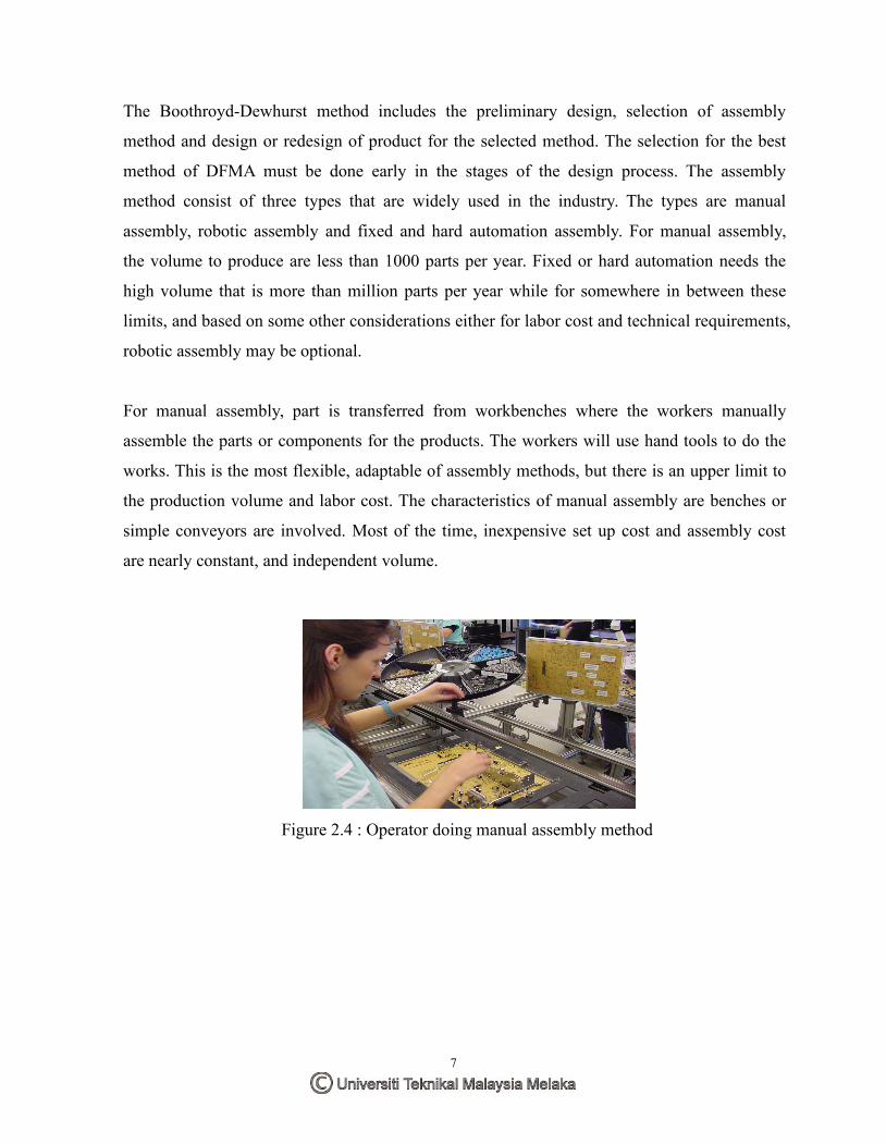
For manual assembly, part is transferred from workbenches where the workers manually
assemble the parts or components for the products. The workers will use hand tools to do the
works. This is the most flexible, adaptable of assembly methods, but there is an upper limit to
the production volume and labor cost. The characteristics of manual assembly are benches or
simple conveyors are involved. Most of the time, inexpensive set up cost and assembly cost
are nearly constant, and independent volume.
Figure 2.4 : Operator doing manual assembly method

8
Fixed or hard-automation is characterized by a custom-built machine that assembles one and
only one specific product. This type of machinery requires a large capital investment. As
production volume increases, the fraction of the capital investments compared to the total
manufacturing cost decreases. Sometimes, this kind of assembly called as ‘Detroit-type’
assembly. The characteristics of fixed and hard automation assembly are the components
involved are parts feeders, single purpose work heads and transfer devices. It is very expensive
and time-consuming to build, very high production rate and down time due to defective parts
may be a severe problem.
Figure 2.5 : Fixed or hard automation assembly method
Soft automation or robotic assembly incorporates the use of robotic assembly systems. This
can take the form of a single robot or a multi-station robotic assembly cell with all activities
simultaneously controlled and coordinated by a PLC or computer. The characteristics of the
robotic assembly are similar to non-synchronous special propose assembly stations, excepts
robots replace the single-purpose work heads and its use of robots allows flexibility in product
types and production rates. Although this type of assembly method can also have a large
capital cost, its flexibility often helps offset the expenses across many different products.