UNIVERSITI PUTRA MALAYSIA IMPACT OF INLET SLUG FLOW ON ...
35
UNIVERSITI PUTRA MALAYSIA IMPACT OF INLET SLUG FLOW ON HORIZONTAL GAS-LIQUID SEPARATOR LEE SIONG HOONG FK 2019 67
Transcript of UNIVERSITI PUTRA MALAYSIA IMPACT OF INLET SLUG FLOW ON ...
UNIVERSITI PUTRA MALAYSIA
IMPACT OF INLET SLUG FLOW ON HORIZONTAL GAS-LIQUID SEPARATOR
LEE SIONG HOONG
FK 2019 67
© COPYRIG
HT UPMIMPACT OF INLET SLUG FLOW ON HORIZONTAL GAS-LIQUID
SEPARATOR
By
LEE SIONG HOONG
Thesis Submitted to School of Graduate Studies, Universiti Putra Malaysia, in Fulfilment of the Requirements for the Degree of Doctor of Philosophy
November 2018
© COPYRIG
HT UPM
ii
COPYRIGHT
All material contained within the thesis, including without limitation text, logos, icons, photographs and all other artwork, is copyright material of Universiti Putra Malaysia unless otherwise stated. Use may be made of any material contained within the thesis for non-commercial purposes from the copyright holder. Commercial use of material may only be made with the express, prior, written permission of Universiti Putra Malaysia.
Copyright © Universiti Putra Malaysia
© COPYRIG
HT UPM
i
Abstract of thesis presented to the Senate of Universiti Putra Malaysia in fulfilment of the requirement for the degree of Doctor of Philosophy
IMPACT OF INLET SLUG FLOW ON HORIZONTAL GAS-LIQUID SEPARATOR
By
LEE SIONG HOONG
November 2018
Chairman : Professor Thomas Choong Shean Yaw, PhD, P.Eng Faculty : Engineering
This study has demonstrated that the current sizing criteria for a gas-liquid separator commonly used in the industry maybe inadequate. The sizing criteria has not taken into account the inlet flow pattern and fluid hydrodynamics inside the separator. In this study, the inlet flow pattern was showed to have significant impact in the separator sizing and the fluid hydrodynamics inside the separator. The experiment was conducted using a test rig consists of a horizontal gas-liquid separator operating at 45 °C. The liquid was constantly fed at 430 mL/min while the gas flowrate was adjusted to meet the requirement of inlet momentum from 200 to 2500 Pa. The liquid and gas phase used in the experiment were water and air, respectively. Experimental results demonstrated that the inlet flow was slug flow for inlet momentum of 200 to 1500 Pa, and the Mandhane’s map could be used to predict the flow pattern.
Computational Fluids Dynamics (CFD) has demonstrated its function as an essential tools to simulate hydrodynamic inside the separator. However, the standard approach for Volume of Fluids (VOF) does not able to model the hydraulic jump in the inlet slug flow and additional User Define Function (UDF) using normal distribution equation was used at the inlet boundary to simulate the hydraulic jump. Another advantage was demonstrated using CFD in this study is the complex calculation such as kinetic energy of turbulence can be solved easily. Realizable turbulence model has provided good agreement with experimental result and is recommended for this type of application.
At inlet momentum of 800 Pa and lower, the sloshing does not occurred in the separator and the Souders-Brown constant from the guidelines is still valid for gas phase section sizing for horizontal gas-liquid separator which provided acceptable
© COPYRIG
HT UPM
ii
low level liquid carryover at gas phase. For inlet momentum of 1000 Pa and higher, the impact of inlet slug flow initiated the separator sloshing phenomena. Sloshing was found to increase the liquid carryover in the gas phase. Kinetic energy of turbulence at liquid phase shall be kept below 15 m2/s2 to avoid any sloshing in the separator. The sloshing phenomena in the separator can be avoided by lowering the liquid level in the separator which is a very economical approach in retrofitting gas-liquid separator and to avoid expensive separation internals. Additional recommended liquid level from this study was suggested in the gas-liquid separator sizing in order to mitigate the sloshing phenomena in the separator.
© COPYRIG
HT UPM
iii
Abstrak tesis yang dikemukakan kepada Senat Universiti Putra Malaysia sebagai memenuhi keperluan untuk ijazah Doktor Falsafah
KESAN OLEH ALIRAN SLUG DI DALAM PEMISAH GAS-CECAIR MENDATAR
Oleh
LEE SIONG HOONG
November 2018
Pengerusi : Professor Thomas Choong Shean Yaw, PhD, P.Eng Fakulti : Kejuruteraan
Kajian ini telah menunjukkan kriteria saiz semasa pemisah gas-cecair yang biasa digunakan dalam industri yang berdasarkan momentum masuk, pemalar Souders-Brown dan masa pengekalan cair adalah tidak mencukupi. Kriteria saiz semasa tidak mengambil kira corak aliran masuk dan hidrodinamik cecair di dalam pemisah akibat daripada kesan corak aliran masuk. Dalam kajian ini, corak aliran masuk (inlet slug flow) menunjukkan kesan yang ketara dalam saiz pemisah dan hidrodinamik bendalir di dalam pemisah. Eksperimen ini dijalankan dengan menggunakan rig ujian dua fasa atmosfera yang terdiri daripada pemisah gas-cecair mendatar dan operasi pada suhu 45 OC. Aliran cecair yang digunakan adalah 430 mL/min manakala aliran gas disesuaikan dengan memenuhi syarat momentum masuk dari 200 hingga 2500 Pa. Fasa cecair dan gas yang digunakan dalam eksperimen adalah air dan udara masing-masing. Keputusan eksperimen telah membuktikan bahawa inlet slug flow berlaku di antara momentum masuk 200 hingga 1500 Pa dan peta Mandhane menunjukkan persetujuan terbaik dengan hasil eksperimen.
Dynamics Fluid Dynamics (CFD) telah menunjukkan fungsinya sebagai alat penting untuk mensimulasikan hidrodinamik dalam pemisah. Walau bagaimanapun, pendekatan standard untuk Volume Fluid (VOF) tidak dapat memodelkan lompatan hidraulik dalam inlet slug flow dan User Define Function (UDF) menggunakan persamaan edaran normal digunakan di sempadan masuk untuk mensimulasikan lompatan hidraulik. Kelebihan lain ditunjukkan dengan menggunakan CFD dalam kajian ini adalah pengiraan kompleks seperti tenaga kinetik turbulen boleh diselesaikan dengan mudah. Model turbulen k-ε yang boleh diperolehi telah memberikan persetujuan yang baik dengan keputusan eksperimen dan disyorkan untuk jenis aplikasi ini.
© COPYRIG
HT UPM
iv
Pada momentum masuk 800 Pa dan ke bawah, sloshing tidak berlaku dalam pemisah dan pemalar Souders-Brown untuk fasa gas masih berada di dalam lingkungan garis panduan yang ditetapkan, oleh itu, pengalihan cecair pada fasa gas berada di tahap rendah yang boleh diterima. Fenomena sloshing berlaku akibat dripada inlet slug flow untuk momentum masuk 1000 Pa ke atas. Tenaga kinetik turbulens pada fasa cair hendaklah disimpan di bawah 15 m2/s2 untuk mengelakkan fenomena sloshing di dalam pemisah. Fenomena sloshing di dalam pemisah boleh dielakkan dengan menurunkan tahap cecair di dalam pemisah dan merupakan pendekatan yang sangat ekonomik semasa pengubahsuaian pemisah gas-cair dan mengelakkan penggunaan pemisahan dalaman yang mahal. Tahap cecair tambahan yang dicadangkan dari kajian ini untuk pemisah gas-cecair dapat melenyapkan fenomena sloshing di pemisah.
© COPYRIG
HT UPM
v
ACKNOWLEDGEMENTS
Although my name appears on the cover of this thesis, the accomplishment of this thesis may not be successful without aid and help from many people.
First of all, I would like to address my sincere thanks to all the staffs in Universiti Putra Malaysia especially my supervisor, Professor Ir. Dr. Thomas Choong Shean Yaw and my both co-supervisors, Professor Dr. Luqman Chuah Abdullah and Dr. Mus’ab Abdul Razak for their guidance and ideas throughout the whole period of this study.
Then it is my pleasure to deepest gratitude to Mr. William Lee and Mr. Choong Thin Choy for their financial support in setting up the test rig and Encik Adli Nazri Mohd Kasim for his guidance in laboratory procedures which expedited the progress of the experiment.
Finally I would like to thank my family, my friends and especially my wife, Cerlyn Yee for their unflagging love, support and patience throughout this period.
© COPYRIG
HT UPM
© COPYRIG
HT UPM
vii
This thesis was submitted to the Senate of the Universiti Putra Malaysia and has been accepted as fulfilment of the requirement for the degree of Doctor of Philosophy. The members of the Supervisory Committee were as follows:
Thomas Choong Shean Yaw, PhD, P.Eng Professor, Ir Faculty of Engineering Universiti Putra Malaysia (Chairman)
Luqman Chuah Abdullah, PhD Professor Faculty of Engineering Universiti Putra Malaysia (Member)
Mus’ab Abdul Razak, PhDSenior Lecturer Faculty of Engineering Universiti Putra Malaysia (Member)
ROBIAH BINTI YUNUS, PhD Professor and Dean School of Graduate Studies Universiti Putra Malaysia
Date:
© COPYRIG
HT UPM
viii
Declaration by graduate student
I hereby confirm that: this thesis is my original work; quotations, illustrations and citations have been duly referenced; this thesis has not been submitted previously or concurrently for any other degree
at any other institutions; intellectual property from the thesis and copyright of thesis are fully-owned by
Universiti Putra Malaysia, as according to the Universiti Putra Malaysia (Research) Rules 2012;
written permission must be obtained from supervisor and the office of Deputy Vice-Chancellor (Research and Innovation) before thesis is published (in the form of written, printed or in electronic form) including books, journals, modules, proceedings, popular writings, seminar papers, manuscripts, posters, reports, lecture notes, learning modules or any other materials as stated in the Universiti Putra Malaysia (Research) Rules 2012;
there is no plagiarism or data falsification/fabrication in the thesis, and scholarly integrity is upheld as according to the Universiti Putra Malaysia (Graduate Studies) Rules 2003 (Revision 2012-2013) and the Universiti Putra Malaysia (Research) Rules 2012. The thesis has undergone plagiarism detection software.
Signature: _______________________ Date: __________________
Name and Matric No.: Lee Siong Hoong, GS46504
© COPYRIG
HT UPM
ix
Declaration by Members of Supervisory Committee
This is to confirm that: the research conducted and the writing of this thesis was under our supervision; supervision responsibilities as stated in the Universiti Putra Malaysia (Graduate
Studies) Rules 2003 (Revision 2012-2013) are adhered to.
Signature:Name of Chairman of Supervisory Committee: Professor Ir Dr. Thomas Choong Shean Yaw
Signature:Name of Memberof Supervisory Committee: Professor Dr. Luqman Chuah Abdullah
Signature:Name of Memberof Supervisory Committee: Dr. Mus’ab Abdul Razak
© COPYRIG
HT UPM
x
TABLE OF CONTENTS
Page
ABSTRACT iABSTRAK iiiACKNOWLEDGEMENTS vAPPROVAL viDECLERATION viiiLIST OF TABLES xiiLIST OF FIGURES xiiiLIST OF ABBREVIATIONS xvii
CHAPTER
1 INTRODUCTION 1 1.1 Upstream Production 1 1.2 Gas-Liquid Separators in Production 2 1.3 Problem Statement 3 1.4 Objectives 3 1.5 Scope of the Research 4
2 LITERATURE REVIEW 5 2.1 Horizontal Gas-Liquid Separator Background 5 2.2 Primary Sizing Criteria for Horizontal Gas-Liquid Separator 6 2.3 Secondary Sizing Criteria for Horizontal Gas-Liquid
Separator 11 2.4 Hydrodynamics in a Separator 14 2.5 Flow Pattern 17
2.5.1 Mandhane‘s Map 18 2.5.2 Taitel & Dukler’s Map 19
2.6 Computational Fluid Dynamics (CFD) - Volume of Fluids (VOF) 20
2.7 Summary 23
3 MATERIAL AND METHOD 24 3.1 Experimental Setup 24
3.1.1 Gas-Liquid Test Rig 24 3.1.2 Gas-Liquid Test Rig Operating Procedure 27
3.2 Liquid (Water) Physical Characterization 29 3.2.1 Viscosity Measurement 29 3.2.2 Density Measurement 31 3.2.3 Surface Tension Measurement 32
3.3 Computational Fluid Dynamics (CFD) Setup 34 3.3.1 Model of Gas-Liquid Separator 34 3.3.2 Meshing of the Model 35 3.3.3 Simulation Model Selection 38
© COPYRIG
HT UPM
xi
3.3.3.1 Volume of Fluids (VOF) 38 3.3.3.2 Turbulence Model - Realizable Model 39
3.3.4 Boundary Condition 41 3.3.5 Discretization Method 43 3.3.6 Solution Method 46
4 RESULTS AND DISCUSSION 48 4.1 Experimental Results and Discussion for Air-Water at
Separator 48 4.1.1 Experiment Observation for Inlet Flow Pattern at
Separator 48 4.1.2 Experiment Observation for Hydrodynamics inside
the Separator 53 4.1.3 Analysis using Two-Phase Flow Pattern Map 60
4.2 Modelling Inlet Flow Pattern Using Numerical Models 62 4.2.1 Standard Approach of Volume of Fluid (VOF)
Simulation for Inlet Flow Pattern 62 4.2.2 Inlet Flow Pattern with User Define Function (UDF) 63
4.3 Hydrodynamics Inside the Separator 71 4.4 Amplifications of Inlet Momentum 78 4.5 Liquid Carryover at Gas Outlet 80 4.6 Kinetic Energy of Turbulence 83 4.7 Implementation of Outcomes from this Study in a Separator
Sizing 87 4.8 Summary 90
5 CONCLUSION AND RECOMMENDATIONS 91
REFERENCES 92 BIODATA OF STUDENT 100 LIST OF PUBLICATIONS 101
© COPYRIG
HT UPM
xii
LIST OF TABLES
Table Page
2.1 Type of Inlet Device and their Inlet Momentum Limit 8
2.2 Recommendation K-value for Different Type of Demister for Gas-Liquid Separator 10
2.3 Adjustment of K- value for Pressure Elevation 10
2.4 Recommended Retention time for Gas-Liquid Separator 11
3.1 Basis of Design of In-House Gas-Liquid Test Rig 25
3.2 Test Matrix of the Experiment at 101.325 kPa and 45 OC 28
3.3 Physical Data of Liquid (Water) 33
3.4 Data of the Boundary Condition Used in the ANSYS Fluent Version 17.2 42
4.1 Velocity Contour of Inlet due to Slug Flow 79
4.2 Modification Data for Test Separator (Pertamina, 2012a) 88
© COPYRIG
HT UPM
xiii
LIST OF FIGURES
Figure Page
1.1 Typical Schematic Diagram of a Production Facility 1
2.1 Four Sections in the Gas-Liquid Separator (Jack, 2009) 5
2.2 Different Types of Inlet Devices (Arnold, 2007; Chin, 2015a; 2015b) 7
2.3 Forces Exerted on a Droplet 9
2.4 Droplet Size Distribution in a Separator (Campbell, 1992) 11
2.5 Drag Coefficient for Sphere as a Function of Reynolds number (McCabe et al., 1993) 12
2.6 Drag Coefficients for Varying Magnitudes of Reynolds Number (Arnold & Stewart, 2008b) 13
2.7 Formation of Cavity (Labus & Aydelott, 1971) 15
2.8 Flow Pattern of Horizontal Co-current Flow (Spedding et al., 2003) 18
2.9 Mandhane’s Map for Horizontal Flow Model (Mandhane et al., 1974) 19
2.10 Taitel & Dukler’s Map for Horizontal Flow Model (Taitel & Dukler, 1976) 20
3.1 An Outline of the Study Approach Adopted in this Work 24
3.2 Setup of Gas-Liquid (Two-Phase) Test Rig 25
3.3 Schematic of Gas-Liquid (Two-Phase) Test Rig 26
3.4 Gas-Liquid Separator 26
3.5 An Illustration of Glass Capillary Viscometer 30
3.6 Glass Capillary Viscometer used in Experiment 30
3.7 Glass Capillary Viscometer in Water Batch 31
3.8 KEM DA-650 Density Meter Used in the Experiment 32
© COPYRIG
HT UPM
xiv
3.9 An Illustration of Maximum Force of the Pulling Ring before the Liquid Surface Formation Rupture 32
3.10 An Illustration of Measuring Phases Using Du Noüy Ring Method 33
3.11 Lauda Tensiometer TD1C Used in the Experiment 33
3.12 Gas-Liquid Separator Model 35
3.13 Gas-Liquid Separator with 1.7 mm Tetrahedron Mesh 36
3.14 Mesh Dependency Test of Single Section 36
3.15 Comparison of Various Improved Mesh Size 37
3.16 Comparison of Selected Improved Mesh Size and Single Mesh of 1.5 and 1.7 mm 37
3.17 Visual Comparison of Single Mesh (Left) and Dual Mesh (Right) 38
3.18 Control Volume Used to Illustrate Discretization of a Scalar Transport Equation (ANSYS Fluent, 2016) 43
3.19 Cell Centroid Evaluation (ANSYS Fluent, 2016) 44
3.20 Pressure-based Segregated Algorithm Solution Method 47
4.1 Flow Behavior for Inlet Momentum 200 Pa 48
4.2 Flow Behavior for Inlet Momentum 400 Pa 49
4.3 Flow Behavior for Inlet Momentum 600 Pa 49
4.4 Flow Behavior for Inlet Momentum 800 Pa 49
4.5 Flow Behavior for Inlet Momentum 1000 Pa 50
4.6 Flow Behavior for Inlet Momentum 1500 Pa 50
4.7 Flow Behavior for Inlet Momentum 2000 Pa 51
4.8 Flow Behavior for Inlet Momentum 2500 Pa 51
4.9 An Illustration of Impact of Slug Flow onto the Liquid Surface inside the Separator during Hydraulic Jump. 52
4.10 Annular Flow Pattern in a Conventional Pipe (Li et al., 2017) 52
© COPYRIG
HT UPM
xv
4.11 Experiment Observation for Hydrodynamics inside the Separator for 200 Pa 54
4.12 Experiment Observation for Hydrodynamics inside the Separator for 400 Pa 55
4.13 Experiment Observation for Hydrodynamics inside the Separator for 600 Pa 56
4.14 Experiment Observation for Hydrodynamics inside the Separator for 800 Pa 57
4.15 Experiment Observation for Hydrodynamics inside the Separator for 1000 Pa 58
4.16 Experiment Observation for Hydrodynamics inside the Separator for 1500 Pa 59
4.17 Sloshing in the Separator 60
4.18 Flow Pattern Prediction using Taitel & Dukler (1976) Map 60
4.19 Flow Pattern Prediction using Mandhane et al. (1974) Map 61
4.20 Comparison of Inlet Flow Pattern of Experiments (Top) and Simulations (Bottom) using Volume of Fluid Approach 62
4.21 Comparison of Actual and Simulated Inlet Liquid Volume Distribution in the VOF Approach 63
4.22 Generic Normal Distribution (Bell) Curve 64
4.23 Straight Pipe Model (Left) and Straight Pipe with Mesh (Right) 65
4.24 Comparison of Different Mesh Size of the Straight Pipe 65
4.25 Comparison of ANSYS Fluent Data with Equation 4.2 67
4.26 Comparison of Experiment Observations and Volume Fraction of Water as Simulated by ANSYS Fluent With and Without an UDF 68
4.27 Comparison of Experimental and ANSYS Fluent with UDF at Separator Inlet Section 70
4.28 Comparison of Experimental and Simulated Results for Hydrodynamics inside the Separator for Inlet Momentum of 200 Pa 72
© COPYRIG
HT UPM
xvi
4.29 Comparison of Experimental and Simulated Results for Hydrodynamics inside the Separator for Inlet Momentum of 400 Pa 73
4.30 Comparison of Experimental and Simulated Results for Hydrodynamics inside the Separator for Inlet Momentum of 600 Pa 74
4.31 Comparison of Experimental and Simulated Results for Hydrodynamics inside the Separator for Inlet Momentum of 800 Pa 75
4.32 Comparison of Experimental and Simulated Results for Hydrodynamics inside the Separator for Inlet Momentum of 1000 Pa 76
4.33 Comparison of Experimental and Simulated Results for Hydrodynamics inside the Separator for Inlet Momentum of 1500 Pa 77
4.34 Amplifications of Inlet Momentum due to Hydraulic Jump of Slug Flow 78
4.35 Liquid Carryover at Gas Outlet with Different Inlet Momentum 80
4.36 Hydrodynamics in the Separator for Liquid Level 63mm 82
4.37 Liquid Carryover at Gas Outlet for Inlet Momentum of 1000 and 1500 Pa after Reduction of Liquid Level to Mitigate Sloshing 83
4.38 Kinetic Energy of Turbulence in the Liquid Phase for Different Inlet Momentum 85
4.39 Comparison of Various Kinetic Energy of Turbulence with and without Sloshing Happened in the Separator 86
4.40 Recommendation of Liquid Level in a Separator to Prevent Sloshing 87
4.41 Flowchart of an Improved Procedure for Separator Sizing 88
4.42 Prediction of Inlet Flow Pattern from Mandhane’s Map 89
4.43 Maximum Allowable Liquid Level to Avoid Sloshing for a Case Study90
© COPYRIG
HT UPM
xvii
LIST OF ABBREVIATIONS
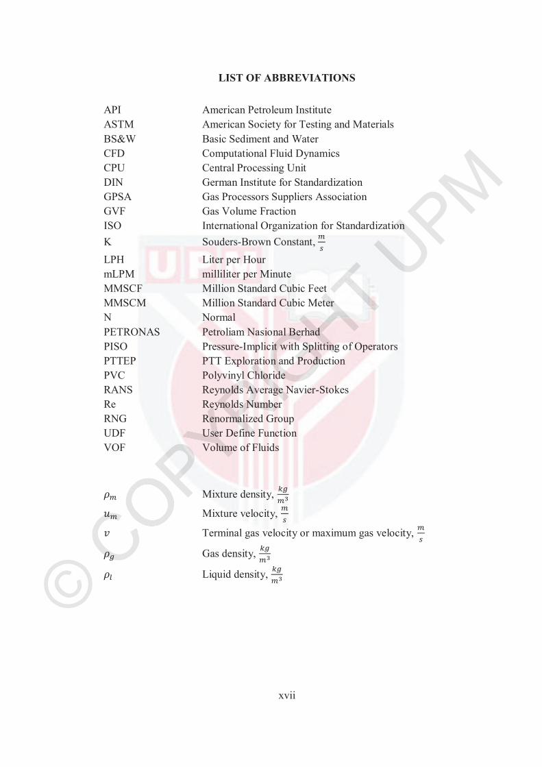
API American Petroleum Institute ASTM American Society for Testing and Materials BS&W Basic Sediment and Water CFD Computational Fluid Dynamics CPU Central Processing Unit DIN German Institute for Standardization GPSA Gas Processors Suppliers Association GVF Gas Volume Fraction ISO International Organization for Standardization K Souders-Brown Constant,LPH Liter per Hour mLPM milliliter per Minute MMSCF Million Standard Cubic Feet MMSCM Million Standard Cubic Meter N Normal PETRONAS Petroliam Nasional Berhad PISO Pressure-Implicit with Splitting of Operators PTTEP PTT Exploration and Production PVC Polyvinyl Chloride RANS Reynolds Average Navier-Stokes Re Reynolds Number RNG Renormalized Group UDF User Define Function VOF Volume of Fluids
Mixture density,
Mixture velocity,
Terminal gas velocity or maximum gas velocity,
Gas density,
Liquid density,
© COPYRIG
HT UPM
1
CHAPTER 1
1 INTRODUCTION
1.1 Upstream Production
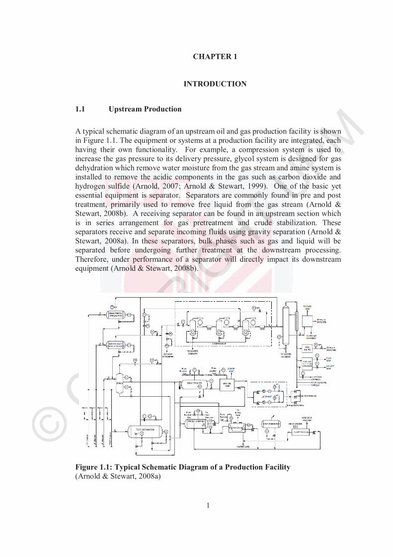
A typical schematic diagram of an upstream oil and gas production facility is shown in Figure 1.1. The equipment or systems at a production facility are integrated, each having their own functionality. For example, a compression system is used to increase the gas pressure to its delivery pressure, glycol system is designed for gas dehydration which remove water moisture from the gas stream and amine system is installed to remove the acidic components in the gas such as carbon dioxide and hydrogen sulfide (Arnold, 2007; Arnold & Stewart, 1999). One of the basic yet essential equipment is separator. Separators are commonly found in pre and post treatment, primarily used to remove free liquid from the gas stream (Arnold & Stewart, 2008b). A receiving separator can be found in an upstream section which is in series arrangement for gas pretreatment and crude stabilization. These separators receive and separate incoming fluids using gravity separation (Arnold & Stewart, 2008a). In these separators, bulk phases such as gas and liquid will be separated before undergoing further treatment at the downstream processing. Therefore, under performance of a separator will directly impact its downstream equipment (Arnold & Stewart, 2008b).
Figure 1.1: Typical Schematic Diagram of a Production Facility(Arnold & Stewart, 2008a)
© COPYRIG
HT UPM
2
1.2 Gas-Liquid Separators in Production
The primary function of a gas-liquid separator is to separate bulk phases using gravitation concept. To ensure a separator to perform as it is, Hansen (2001) has proposed several important criteria for sizing:-
1. Provide sufficient time to allow the immiscible gas and liquid phases toseparate by gravity.
2. Provide sufficient time to allow for the coalescence of gas bubbles in the bulkliquid phase to improve degassing.
3. Allow for variation in the flow rates of gas and liquid without adverselyaffecting separation efficiency. This variation in flow rates is oftenrepresented using inlet momentum.
These sizing criteria will be further explained in Section 2.2.
A separator shall be robust in handling incoming fluids. The incoming fluids from a subsurface flowline enters a separator at different momentum and the magnitude of the incoming fluids are subjected to reservoir pressure, fluids mixture and overall production plan. An ideal separator is designed to withstand and dampen this inertia or commonly known in the industry as inlet momentum.
The performance of a separator is measured in amount of liquid carryover to the gas phase. Liquid carryover in the gas phase from a separator is one of the major issue in an upstream production facility. A liquid carryover to the compressor will lead to imbalance of the impeller and excessive vibration. An excessive liquid carryover may eventually lead to mechanical failure in the long run (Prabhudharwadkar et al., 2010; Ezzell, 2017). In gas processing system such as glycol and amine system, an excess condensate carryover will cause uncontrollable foaming in the contactors (Ezzell, 2017). Moreover, excessive liquid carryover in the flaring system will damage the flare tip and lead to more downtime due to maintenance work and incomplete combustion.
Information on hydrodynamics inside a separator is crucial to unlock the uncertainties in sizing a new separator or retrofitting an existing unit. Besides physical experiment study, numerical simulation can be used to model the phenomena happened in a separator. Computational Fluid Dynamics (CFD) can be a useful tool to review the design or retrofitting of a separator (Laleh et al., 2011b).
© COPYRIG
HT UPM
3
1.3 Problem Statement
As mentioned by Bothamley (2013a), many two-phase separators in the oil and gas industry were reported to underperform, most likely due to inadequate sizing methodology. One of the weakness associated with the current sizing methodology is the lack of quantification of feed flow, where the impact of flow pattern on the performance of a separator is not incorporated.
The current practice, provided by vendor, in rectifying excessive liquid carryover in a gas-liquid separator is often by the installation of advanced separation internals such as inlet device, vane type coalescer and demisting cyclones. However, this approach involves a high retrofitting cost and also adds more weight to the equipment which is unfavorable to the production operators. Note that an investment of millions of ringgit is often required for a major retrofitting (Chin, 2015a; Chin et al., 2015;Morillo et al., 2016; Bothamley (2017)).
In order to achieve a simpler and a more economical solution, a deeper understanding on the behavior of inlet flow and its impact on hydrodynamics inside a separator is necessary. However, there are very few literature reporting the details of inlet flow and its hydrodynamics inside a separator. A detailed study in this particular field is required to realize this approach. The focus of this research will be on slug flow as it is the most common flow pattern encountered in two-phase flow. As mentioned recently by Bothamley (2017), a proper quantification of feed inlet and a proper understanding of hydrodynamics is crucial to prevent liquid carryover in a separator.
1.4 Objectives
This project was designed to study the inlet flow behavior and hydrodynamics inside a separator. A bare separator was used here in order to achieve a simple and economical solution. The specific objectives of this research were as follows:-
1) To study the type and impact of inlet flow on liquid surface movement inside a separator using an in-house gas-liquid separation test rig.
2) To simulate the impact of inlet flow on liquid surface movement inside a separator using CFD simulation – ANSYS Fluent.
3) To simulate and predict the performance of a gas-liquid separator using an experimental validated CFD model. The performance of a separator is quantified using the amount of liquid carryover. A practical guideline for mitigating the liquid carryover is proposed.
© COPYRIG
HT UPM
4
1.5 Scope of the Research
In this study, the focus is on a two-phase or gas-liquid separator as experimental study of a three phase separator involves liquid-liquid phase separation which may require the use of actual crude oil. The Gas Volume Fraction (GVF) for the incoming fluids mixture is in the range of 0.90 to 0.99 where inlet slug flow occurred. The GVF range adopted in this research is commonly found in most separators for both associated and non-associated gas fields. Most of the first separator for associated and non-associated gas fields in this region have operating temperature no more than 45 oC. In this study, experiments were performed at atmospheric pressure and air, and water were used as gas and liquid phase. Furthermore, this work focused on the primary sizing criteria for horizontal gas-liquid separator, in which droplet size of carryover was not included. The droplet size is an additional aspect covered by the secondary sizing criteria for separator. However, this criteria is not mandatory in the industry standard. The experiment in this study was designed to achieve the American Petroleum Institute (API) 17 N Technology Readiness Level 3 for research to prove feasibility where concept was proved by experimental or simulation. (Banke, 2017 and Grethe et. al., 2016)
© COPYRIG
HT UPM
92
6 REFERENCES
Abbruzzese G., Gómez, M. and Cordero-Gracia, M. 2018. Unstructured 2D Grid Generation Using Overset-Mesh Cutting and Single-Mesh Reconstruction. Aerospace Science and Technology 78: 637-647.
Aker Solutions. 2010. Process Datasheet - HP Separator (V-110). Aker Solution Document No EP-CPP-10-DS-0001.
Al-Hadhrami, L. M., Shaahid, S. M., Tunde, L. O. and Al-Sarkhi, A. 2014. Experimental Study on the Flow Regimes and Pressure Gradients of Air-Oil-Water Three-PhaseFlow in Horizontal Pipes. The Scientific World Journal:1-11.
Alves, G. E. 1954. Co-current Liquid/Gas Flow in a Pipeline Contractor. Chemical Enigneering Program: 449-456.
Alves, M. V. C., Waltrich, P. J., Gessner, T. R., Falcone, G. and Barbosa Jr, J. R. 2017. Modelling Transient Churn-Annular Flows in a Long Vertical Tube. International Journal of Multiphase Flow 89: 399-412.
Ambrosia, V. S. 2018. How to Run Fluent Benchmark Cases. Retrived 9 December 2018 from https://support.esss.co/hc/en-us/articles/205250955-How-to-Run-Fluent Benchmark-Cases
American Petroleum Institute. 2008. Specification for Oil and Gas Separators. 8th ed. American Petroleum Institute: Washington D. C.
Andreussi, P., Minervini, A. and Paglianti, A. 1993. Mechanistic Model of Slug Flow in Near-Horizontal Pipes. AIChE Journal 39: 1281-1291.
ANSYS Fluent. 2016. Theory Guide Release 17.2. SAS IP Inc.
Arnold, K. and Stewart, M. 2008a. Surface Production Operations: Design of Oil Handling Systems and Facilities. 3rd ed. United State of America: Gulf Professional Publishing.
Arnold, K. E. 2007. Petroleum Engineering Handbook. 1st ed. Texas: Society of Petroleum Engineers.
Arnold, K. and Stewart, M. 1999. Surface Production Operations: Design of Gas- Handling Systems and Facilities. 2nd ed. United States of America: Gulf Professional Publishing.
Arnold, K. and Stewart, M. 2008b. Gas-Liquid and Liquid Liquid Separators. United States of America: Gulf Professional Publishing.
© COPYRIG
HT UPM
93
Austrheim, T., Gjersten, L. H. and Hoffmann, A. C. 2007. Is the Souders-Brown Equation Sufficient for Scrubber Design? An Experimental Investigation at Elevated Pressure with Hydrocarbon Fluids. Chemical Engineering Science62: 5715-5727.
Austrheim, T., Gjertsen, L. H. and Hoffmann, A. C. 2008a. Experimental Investigation of the Performance of a Large-Scale Scrubber Operating at elevated Pressure on Live Natural Gas. Fuel 87: 1281-1288.
Austrheim, T., Gjertsen, L. H. and Hoffmann, A. C. 2008b. An Experimental Investigation of Scrubber Internals at Condition of Low Pressure. Chemical Engineering Journal, Volume 138: 95-102.
Baker, O. 1954. Simultaneous Flow of Oil and Gas. Oil and Gas Journal 53: 185-195.
Banke, J. 2017. Techonology Readiness Demistified. Retrived 8 December 2018 from https://www.nasa.gov/topics/aeronautics/features/trl_demystified.html
Banks, R. B. and Bhavamai, A. 1965. Experimental Study of the Impingement of aLiquid Jet on the Surface of a Heavier Liquid. Journal of Fluid Mechanics 23: 229-240.
Barth, T. J. and Jespersen, D. C. 1989. The Design and Application of Upwind Schemes on Unstructured Meshes. American Institute of Aeronautics and Astronautics.
Bonzanini, A., Picchi, D., Ferrari, M. and Poesio, P. 2018. Velocity Profiles Description and Shape Factors Inclusion in a Hyperbolic, One-Dimensional, Transient Two-Fluid Model for Stratified and Slug Flow Simulations in Pipes. Petroleum.
Boschee, P. 2014. Sand Separation in Surface Facilities for Heavy and Extra Heavy Oil. Oil and Gas Facilities October: 25-29.
Bothamley, M. 2013a. Gas/Liquid Separator: Quantifying Separation Performance. Oil and Gas Facilities August: 21-29.
Bothamley, M. 2013b. Gas/Liquid Separator - Part 2: Quantifying Separation Performance. Oil and Gas Facilities October: 35-47.
Bothamley, M. 2013c. Gas/Liquid Separator - Part 3: Quantifying Separation Performance. Oil and Gas Facilities December: 34-47.
Bothamley, M. 2017. Quantifying Oil/Water Separation Performance in Three-Phase Separators - Part 2. Retrived 9 June 2018 from https://spe.org/en/print-article/?art=2835
© COPYRIG
HT UPM
94
Brauner, N. and Ullmann, A., 2002. Modelling of Pase Inversion Phenomenon in Two-Phase Pipe Flows. International Journal of Multiphase Flow 28: 1177-1204.
Campbell, J. M. 1992. Gas Conditioning and Processing. 7th ed. Oklahoma: Campbell Petroleum Series.
Cheslak, F. R., Nicholls, A. J. and Sichel, M. 1969. Cavities Formed on Liquid Surfaces by Impinging Gaseous Jets. Journal of Fluid Mechanics 36: 55-63.
Chin, R. 2015a. The Savvy Separator Series: Part 2 - The Effect of Inlet Geometries on Flow Distribution. Oil and Gas Facilities August: 26-31.
Chin, R. 2015b. The Savvy Separator Series: Part 4 - The Ghosts of Separators: Past, Present and Future. Oil and Gas Facilities December: 18-23.
Chin, R., Asperen, V. V., Reisenberg, J. M. and McVinnie, G. 2015. The Savvy Separator Series: Part 3 - Scrubber Debottlenecking October: 22-27.
Chisholm, D. 1967. A Theoretical Basis for the Lockhart-Martinelli Correlation for Two-Phase Flow. Internaltional Journal of Heat and Mass Transfer 10: 1767-1778.
Escue, A. and Cui, J. 2010. Comparison of Turbulence Models in Simulating Swirling Pipe. Applied Mathematical Modelling 34: 2840-2849.
Ezzell, G. 2107. Transtech Fabrication. Retrived 25 May 2018 from https://www.transtechfabrication.com/news/liquids-carry-over-elimination-for-high-liquid-loads.
Farzad, B.-T. and Hamed, Z. 2010. Presumed PDF Modeling of a Reactive Two-Phase Flow in a Three Dimensional Jet-Stabilized Model Combustor. Energy Conversion and Management 51: 225-234.
Frankiewicz, T. and Lee, C. M. 2002. Using Computational Fluid Dynamics (CFD) Simulation to Model Fluid Motion in Process Vessels on Fixed and Floating Platforms. San Antonio: Society of Petroleum Engineres Inc.
Gas Processors Suppliers Association. 2004. GPSA Engineering Data Book. 12th ed. Oklahoma: Gas Processors Suppliers Association.
Ghaffarkhah, A., Shahrabi, M. A., Moraveji, M. K. and Eslami, H. 2016. Application of CFD for Designing Conventional Three Phase Oilfield Separator. Egyptian Journal of Petroleum 26: 413-420.
Govier, G. W. and Aziz, K. 1972. The Flow of Complex Mixtures in Pipes. New York: Van Nostrand-Reinhold.
© COPYRIG
HT UPM
95
Govier, G. W. and Omer, M. M. 1962. The Horizontal Pipeline Flow of Air-Water Mixtures. The Canadian Journal of Chemical Engineering: 93-104.
Guha, D., Ramachandran, P. A. and Dudukovic, M. P. 2008. Evaluation of Large Eddy Simulation and Euler-Euler CFD Models for Solids Flow Dynamics in a Stirred Tank Reactor. Wiley InterScience 54: 766-778.
Gupta, A. and Kumar, R. 2007. Three-Dimensional Turbulent Swirling Flow in a Cylinder: Experimentals and Computations. International Journal of Heat and Fluid 28: 249-261.
Grethe, K., Thomas, M., Monica, B. and Ute, B. TRL (Technology Readiness Level) Assessment of DREAM (Dose-related Risk and Effects Assessment Model) to Qualify its Use for Modelling of Produced Water and Drilling Discharges.Stavanger: Society of Petroleum Engineres Inc.
Hansen, E. W. M. 2001. Phenomeological Modelling and Simulation of Fluid Flow and Separation Behaviour in Offshore Gravity Separators. PVP-Vol.431, Emerging Technologies for FLuids, Structures and Fluid-Structure Interaction: 23-29.
Höhne, T. and Hänsch, S. 2015. A Droplet Entrainment Model for Horizontal Segregated Flows. Nuclear Engineering and Design 286: 18-26.
Hoogendoorn, C. J. 1959. Gas-liquid flow in horizontal pipes. Chemical Engineering Science 9: 205-217.
Jack, 2009. Oil & Gas Process Engineering. Retrived 21 May 2018 from http://www.oilngasprocess.com/oil-handling-surfacefacilities/two-phase-oil-and-gas-separation/horizontal-two-phase-separator.html
Jawarneh, A. M., Tlilan, H., Al-Shyyab, A. and Ababneh, A. 2008. Strongly Swrling Flows in a Cylindrical Separator. Minerals Engineering 21: 366-372.
Jerzy, H. 2010. Phase Inversion in Liquid-Liquid Pipe Flow. Flow Measurement and Instrumentation 21: 284-291.
Johannessen, T. 1972. A Theoretical Solution of the Lockhart and Martinelli Flow Model for Calculating Two-Phase Flow Pressure Drop and Hold-Up. International Journal of Heat and Mass Transfer 15: 1443-1449.
Karadimou, D. P., Papadopoulos, P. A. and Markatos, N. C. 2017. Mathematical Modelling and Numerical Simulation of Two-Phase Gas-Liquid Flows in Stirred-Tank Reactors. Journal of King Saud University - Science: 1-9.
Katapodis, L. 1977. Oil and Gas Separation Theory, Application and Design. Society of Petroleum Engineers: 85-89.
© COPYRIG
HT UPM
96
Kharoua, N., Khezzar, L. and Saadawi, H. 2013. CFD Modelling of a Horizontal Three-Phase Separator: A Population Balance Approach. American Journal of Fluid Dynamics: 101-118.
Kim, S. E., Makarov, B. and Caraeni, D. 2003. A Muilti-Dimensional Linear Reconstruction Scheme for Arbitrary Unstructured Grids. American Institute of Aeronautics and Astronautics: 1-11.
Labus, T. L. and Aydelott, J. C. 1971. Gas-Jet Impingement Normal to a Liquid Surface. Washington D. C.: National Aeronautics and Space Administration.
Laleh, A. P., Svrcek, W. Y. and Monnery, W. D. 2011a. Computational Fluid Dynamics Simulation of Pilot-Plant-Scale Two-Phase Separators. Chemical Engineering and Technology 34: 296-306.
Laleh, A. P., Svrek, W. Y. and Monnery, W. D. 2011b. Design and CFD Studies of Multiphase Separators - A Review. The Canadian Journal of Chemical Engineering: 1-14.
Laleh, A. P., Svrek, W. Y. and Monnery, W. D. 2012. Computational Fluid Dynamics – Based Study of an Oilfield Separator - Part I: A Realistic Simulation. Oil and Gas Facilities December: 57-68.
Laleh, A. P., Svrek, W. Y. and Monnery, W. D. 2013. Computational Fluid Dynamics – Based Study of an Oilfield Separator - Part II: An Optimum Design. Oil and Gas Facilities February: 52-59.
Lienhard, J. H., 1968. Capillary Action in Small Jets Impinging on Liquid Surfaces. Journal of Basic Engineering, pp. 137-138.
Li, H., Li, J., Zhou, Y., Liu, B., Sun, B., Yang, D. and Fan, X. 2017. Phase Split Charaterictics of Slug and Annular Flow in a Dividing Micro-T-Junction. Experimental Thermal and Fluid Science 80: 244-258.
Lin, S., Chin, Y., Wu, C., Lin, J. and Chen, Y. 2012. A Pressure Correction-Volume of Fluid Method for Simulation of Two-Phase Flows. International Journal for Numerical Methods in Fluids: 181-195.
Lockhart, R. W. and Martinelli, R. C. 1949. Proposed Correlation of Data for Isothermal Two-Phase, Two-Component Flow in Pipes. Chemical Engineering Progress: 38-48.
Mandhane, J. M., Gregory, G. A. and Aziz, K. 1974. A Flow Pattern Map for Gas-Liquid Flow in Horizontal Pipes. Int. J. Multiphase Flow 1: 537-553.
Mata, C., Pereyra, E., Trallero, J. L. and Joseph, D. D. 2002. Stability of Stratified Gas-Liquid Flows. International Journal of Multiphase Flow 28: 1249-1268.
© COPYRIG
HT UPM
97
McCabe, W. L., Smith, J. C. & Harriott, P., 1993. Unit Operations of Chemical Engineering. 5th ed. Singapore: McGraw Hill Inc.
Miyoshi, M., Doty, D. R. and Schmidt, Z. 1988. Slug-Catcher Design for Dynamic Slugging in an Offshore Production Facility. SPE Production Enigneering: 563-573.
Moncho-Esteve, I. J., Gasque, M., González-Altozano, P. and Palau-Salvador, G. 2017. Simple Inlet Devices and Their Influence on Thermal Stratification in a Hot Water Storage Tank. Energy and Building 150: 625-638.
Morillo, E., Asperen, V. V. and Sander, B. 2016. The Savvy Separator Series: Underperforming Gas Scrubbers - How to Fix Them and How to Avoid Them April: 16-23.
NOV. 2018. Inlet Separator - Process Data Sheet. NOV Document No. 1526-NV-20-P-DS-00001.
Obara, T., Bourne, N. K. and Field, J. E. 1995. Liquid-Jet Impact on Liquid and Solid Surfaces. Wear: 388-394.
Ozan, A. Y. and Yüksel, Y. 2010. Simulation of a 3D Submerged Jet Flow Around a Pile. Ocean Engineering 37: 819-832.
Park, I. R., Kim, K. S. and Van, S. H. 2009. A Volume-of-Fluid Method for Incompressible Free Surface Flows. International Journal for Numerical Methods in Fluids 61: 1331-1361.
Pertamina. 2012a. Process Data Sheet for Test Separator (SNO-V-1104 & SNO-V-1204). Pertamina Document No SNO-R-DS-10-004 .
Pertamina. 2012b. Process Data Sheet for Production Separator (SNO-V-1102 & SNO-V-1202). Pertamina Document No SNO-R-DS-10-003.
PETRONAS Technical Standards. 2015. PTS 16.52.09: Two Phase Gas and Liquid Separator. Kuala Lumpur: PETRONAS Technical Standards.
Piela, K. et al. 2008. On the Phase Inversion Process in an Oil-Water Pipe Flow. International Journal of Multiphase Flow 34: 665-677.
Pozzetti, G., Jasak, H., Besseron, X., Rousset, A. and Peters, B. 2019. A Parallel Dual-Grid Multiscale Approach to CFD-DEM Couplings. Journal of Computational Physics 378: 708-722.
Prabhudharwadkar, D. M., More, R. Z. and Iyer, K. N. 2010. Experimental Study of Liquid Carryver in a Separator Drum. Nuclear Engineering and Design 240: 76-83.
© COPYRIG
HT UPM
98
PTTEP. 2012. PTTEP Engineering General Specification (PEGS) - Process Sizing Criteria. Thailand: PTT Exploration and Production Public Company Limited.
Rajagounder, R., Mohanasundaram, G. V. and Kalakkath, P. 2015. A Study of Liquid Sloshing in an Automotive FUel Tank under Uniform Acceleration. Engineering Journal 20: 71-85.
Rizzi, A. W. and Inouye, M. 1973. Time-Split Finite-Volume Method for Three- Dimensional Blunt-Body Flow. American Institute of Aeronautics and Astronautics Journal 11: 1478-1485.
Rosler, R. S. and Stewart, G. H. 1968. Impingement of Gas Jets on Liquid Surfaces. Journal of Fluid Mechanics 31: 163-174.
Shell. 2007. Gas/Liquid Separators - Type Selection and Design Rules. The Netherlands: Shell Global Solutions International B. V.
Shih, T. H. 1997. Some Developments in Computaional Modeling of Turbulent Flows. Fluid Dynamics Research 20: 67-96.
Shih, T. H., Liou, W. W., Shabbir, A., Yang, Z. and Zhu, J. 1994. A New k-ε Eddy Viscosity Model for High Reynolds Number Turbulent Flows - Model Development and Validation. Cleveland: Institute for Computational Mechanics in Propulsion and Center for Modeling of Turbulence and Transition, Lewis Research Center.
Sidi-Ali, K. and Gatignol, R. 2010. Interfacial Friction Factor Determination using CFD
Simulations in a Horizontal Stratified Two-Phase Flow. Chemical Engineering Science 65: 5160-5169.
Souders, M. and Brown, G. G. 1934. Design of Fractionating Columns - I. Entrainment and Capacity. Industrial and Engineering Chemistry: 98-103.
Spedding, P. L., Cooper, R. K. and McBride, W. J. 2003. A Universal Flow Regime Map for Horizontal Two-Phase Flow in Pipes. Developments in Chemical Engineering and Mineral Processing 11: 95-106.
Sun, X., Zhang, Z. and Chen, D.R. 2017. Numerical Modelling of Miniature Cyclone. Powder Technology 320: 325-339.
Swanborn, R. A., Koene, F. and De Graauw, J. 1995. New Separator Internals Cut Revamping Costs. Journal of Petroleum Technology 47: 688-692.
Taitel, Y. and Dukler, A. E. 1976. A Model for Predicting Flow Regime Transitions in Horizontal and Near Horizontal Gas-Liquid Flow. AIChE Journal 22: 47-55.
© COPYRIG
HT UPM
99
Tunstall, R., Laurance, D., Prosser, R. and Skillen, A. 2017. Towards a Generalised Dual-Mesh Hybrid LES/RANS Framework with Improved Consistency. Computers & Fluids 157: 73-83.
Total. 2012. General Specification Process - Process Sizing Criteria. Total.
Valencia, A., Paredes, R., Rosales, M., Godoy, E. and Ortega, J. 2004. Fluid Dynamics of Submerged Gas Injection into Liquid in a Model of Copper Converter. International Communications in Heat and Mass Transfer 31: 21-30.
Vallee, C., Lucas, D., Beyer, M., Pietruske, Schutz, P. and Carl, H. 2010. Experimental CFD Grade Data for Stratified Two-Phase Flows. Nuclear Engineering and Design 240: 2347-2356.
Wai, L. L., Valente, H., Nguyen, D. T., Thiam, T. W., Zhao, Y. and Vivek, K. P. 2016. Experimental Study of the Effect of Pressure and Gas Density on the Transistion From Stratified to Slug Flow in a Horizontal Pipe. International Journal of Multiphase Flow 85: 196-208.
Zheng, D., He, X. and Che, D. 2007. CFD Simulation of Hydrodynamic Characteristics in a Gas-Liquid Vertical Upward Slug Flow. International Journal of Heat and Mass Transfer 50: 4151-4165.
© COPYRIG
HT UPM
100
7 BIODATA OF STUDENT
Lee Siong Hoong was born on January 2nd, 1980 in Kuala Lumpur, Malaysia. He enrolled into Universiti Malaysia Sabah in 2000 and received his bachelor degree in Chemical Engineering with honours in 2004. Subsequently, he completed his master degree in Universiti Putra Malaysia in 2006 and was awarded a Master degree in Environmental Engineering. He has 14 years’ experience in oil and gas upstream production specializing in separation, filtration and mass transfer equipment. His experiences extended to oversea projects during his placement in United State of America, China and The Netherlands while working for Perry Filtration Sdn Bhd, ASCOM Asia Pacific Sdn Bhd and Technology Group of PETRONAS. He is a corporate member of Institution of Engineers Malaysia and registered Professional Engineer with Practicing Certificate from Board of Engineers Malaysia since 2010.
© COPYRIG
HT UPM
101
8 LIST OF PUBLICATIONS
Lee Siong Hoong, Thomas S.Y. Choong, Luqman Chuah Abdullah, Mus`ab Abdul Razak, Ban Zhen Hong. Experimental and CFD Modelling: Impact of the Inlet Slug Flow on the Horizontal Gas–Liquid Separator. Energies (Q2), 2019, (Accepted)
Lee Siong Hoong, Thomas S.Y. Choong, Luqman Chuah Abdullah, Mus`ab Abdul Razak, Ban Zhen Hong. Impact of Incoming Flow Momentum on Hydrodynamics of a Horizontal Gas-Liquid Separator. Key EngineeringMaterials (Scopus), 2019, (Accepted)
© COPYRIG
HT UPM