UNITY® XG-100M Mobile Radio - Harris · Operator’s Manual 14221-1200-2000 Rev. G, June 2018...
64
Operator’s Manual 14221-1200-2000 Rev. G, June 2018 UNITY® XG-100M Mobile Radio Full-Spectrum Multiband Radio With CH-721 Control Head
Transcript of UNITY® XG-100M Mobile Radio - Harris · Operator’s Manual 14221-1200-2000 Rev. G, June 2018...

Operator’s Manual 14221-1200-2000
Rev. G, June 2018
UNITY® XG-100M Mobile Radio Full-Spectrum Multiband Radio
With CH-721 Control Head

14221-1200-2000, Rev. G
2
MANUAL REVISION HISTORY
REV DATE REASON FOR CHANGE - May/11 Initial Release. A Oct/11 Added antenna. B Jan/13 Updated to include R3A features. C Mar/13 Updated to include R3B features. D May/14 Included manual channel entry, protected keys, and Talk-Around indication. E Sep/14 Updated for XGP R4A – added Voice Annunciation and Radio TextLink. F Apr/15 Updated for XGP R5A and incorporated addendum. G Jun/18 Updated Table 6-6 and added Section 6.22.
ACKNOWLEDGEMENT This device is made under license under one or more of the following US patents: 4,590,473; 4,636,791; 5,148,482; 5,185,796; 5,271,017; 5,377,229; 4,716,407; 4,972,460; 5,502,767; 5,146,497; 5,164,986; 5,185,795; 5,226,084; 5,247,579; 5,491,772; 5,517,511; 5,630,011; 5,649,050; 5,701,390; 5,715,365; 5,754,974; 5,826,222; 5,870,405; 6,161,089; and 6,199,037 B1. DVSI claims certain rights, including patent rights under aforementioned U.S. patents, and under other U.S. and foreign patents and patents pending. Any use of this software or technology requires a separate written license from DVSI.
CREDITS Harris and Unity are registered trademarks, and TECHNOLOGY TO CONNECT, INFORM AND PROTECT is a trademark of Harris Corporation. All other brand and product names are trademarks, registered trademarks, or service marks of their respective holders. Windows is a registered trademark of Microsoft, Corp. AMBE is a registered trademark and IMBE, AMBE+, and AMBE+2 are trademarks of Digital Voice Systems, Inc.
NOTICE! The material contained herein is subject to U.S. export approval. No export or re-export is permitted without written approval from the U.S. Government. Rated: EAR99; in accordance with U.S. Dept. of Commerce regulations 15CFR774, Export Administration Regulations. Information and descriptions contained herein are the property of Harris Corporation. Such information and descriptions may not be copied or reproduced by any means, or disseminated or distributed without the express prior written permission of Harris Corporation, PSPC Business, 221 Jefferson Ridge Parkway, Lynchburg, VA 24501. Repairs to this equipment should be made only by an authorized service technician or facility designated by the supplier. Any repairs, alterations or substitutions of recommended parts made by the user to this equipment not approved by the manufacturer could void the user's authority to operate the equipment in addition to the manufacturer's warranty.
This product conforms to the European Union WEEE Directive 2012/19/EU. Do not dispose of this product in a public landfill. Take it to a recycling center at the end of its life.
Harris products comply with the Restriction of the Use of Certain Hazardous Substances in Electrical and Electronic Equipment (RoHS) Directive.
This manual is published by Harris Corporation without any warranty. Improvements and changes to this manual necessitated by typographical errors, inaccuracies of current information, or improvements to programs and/or equipment, may be made by Harris Corporation at any time and without notice. Such changes will be incorporated into new editions of this manual. No part of this manual may be reproduced or transmitted in any form or by any means, electronic or mechanical, including photocopying and recording, for any purpose, without the express written permission of Harris Corporation. Copyright © 2011, 2013 – 2015, 2018 Harris Corporation.

14221-1200-2000, Rev. G
3
TABLE OF CONTENTS Page
1. SAFETY SYMBOL CONVENTION .................................................................................................................... 6
2. RF ENERGY EXPOSURE INFORMATION ...................................................................................................... 7 2.1 RF ENERGY EXPOSURE AWARENESS, CONTROL INFORMATION, AND OPERATION
INSTRUCTIONS FOR FCC OCCUPATIONAL USE REQUIREMENTS ................................................ 7 2.1.1 Federal Communications Commission Regulations ...................................................................... 7
2.2 COMPLIANCE WITH RF EXPOSURE STANDARDS ............................................................................ 8 2.2.1 Mobile Antennas (Vehicle Installations) ....................................................................................... 8 2.2.2 Approved Accessories ................................................................................................................... 9 2.2.3 Contact Information ..................................................................................................................... 10
2.3 REGULATORY APPROVALS ................................................................................................................. 10 2.3.1 Part 15 .......................................................................................................................................... 10 2.3.2 Industry Canada ........................................................................................................................... 10
3. OPERATION SAFETY RECOMMENDATIONS ............................................................................................ 11 3.1 TRANSMITTER HAZARDS .................................................................................................................... 11 3.2 SAFE DRIVING RECOMMENDATIONS ............................................................................................... 11
4. OPERATING RULES AND REGULATIONS .................................................................................................. 12
5. PRODUCT DESCRIPTION ................................................................................................................................ 13
6. OPERATION ........................................................................................................................................................ 14 6.1 TURN THE RADIO ON ............................................................................................................................ 14 6.2 CH-721 FRONT PANEL COMPONENTS ............................................................................................... 14 6.3 KEYPAD LOCK/UNLOCK ...................................................................................................................... 15 6.4 RADIO STATUS ICONS .......................................................................................................................... 16 6.5 RADIO MESSAGES.................................................................................................................................. 17 6.6 ALERT TONES ......................................................................................................................................... 19 6.7 MENU ........................................................................................................................................................ 20 6.8 FEATURE ENCRYPTION DISPLAY ...................................................................................................... 21
6.8.1 Serial Number ROM (12 Hex Digits) .......................................................................................... 22 6.8.2 Feature Encryption Data Stream .................................................................................................. 22 6.8.3 Features Enabled.......................................................................................................................... 23
6.9 VOICE ANNUNCIATION ........................................................................................................................ 25 6.10 SYSTEM/GROUP/CHANNEL SELECTION ........................................................................................... 25 6.11 LAST SYSTEM/GROUP/CHANNEL RECALL ...................................................................................... 26 6.12 MACRO KEY OPERATION ..................................................................................................................... 26 6.13 RECEIVE A CALL .................................................................................................................................... 26 6.14 TRANSMIT A CALL ................................................................................................................................ 26 6.15 CONVENTIONAL FAILSOFT (EDACS) ................................................................................................ 27 6.16 EMERGENCY OPERATION .................................................................................................................... 27
6.16.1 Receive an Emergency Call ......................................................................................................... 27 6.16.2 Declare an Emergency ................................................................................................................. 27 6.16.3 Emergency Lock .......................................................................................................................... 28 6.16.4 Stealth Emergency ....................................................................................................................... 28
6.17 MIXED SYSTEM ZONES ........................................................................................................................ 29 6.18 CALLER ID ............................................................................................................................................... 29 6.19 MDC-1200 (CONVENTIONAL ONLY) ................................................................................................... 29
6.19.1 Normal PTT Operation ................................................................................................................ 29 6.19.2 MDC PTT ID Receive Handling ................................................................................................. 30 6.19.3 Emergency Declaration ............................................................................................................... 30
6.20 ENCRYPTION ........................................................................................................................................... 30 6.21 WIDE AREA SYSTEM SCAN (EDACS AND P25 TRUNKED) ............................................................ 30 6.22 SITE LOCK ................................................................................................................................................ 31

14221-1200-2000, Rev. G
4
TABLE OF CONTENTS Page
6.23 PROSCAN (EDACS AND P25 TRUNKED) ........................................................................................... 31 6.24 PRIORITY SYSTEM SCAN (EDACS AND P25 TRUNKED) ............................................................... 31
6.24.1 When Wide Area System Scan is Enabled ................................................................................. 32 6.24.2 When ProScan is Enabled ........................................................................................................... 32
6.25 SCAN OPERATION ................................................................................................................................. 32 6.25.1 Trunked/Conventional Scanning ................................................................................................. 32 6.25.2 Vote Scan .................................................................................................................................... 33 6.25.3 Add Groups/Channels to Scan List ............................................................................................. 33 6.25.4 Delete Groups/Channels from Scan List ..................................................................................... 33 6.25.5 Nuisance Delete .......................................................................................................................... 33 6.25.6 Turn Scan On .............................................................................................................................. 34 6.25.7 Priority Scanning ........................................................................................................................ 34 6.25.8 Turn Scan Off ............................................................................................................................. 34 6.25.9 Mixed Zone Scan ........................................................................................................................ 34
6.26 INDIVIDUAL CALLS (P25 AND EDACS) ............................................................................................. 35 6.26.1 Receive and Respond to an Individual Call ................................................................................ 35 6.26.2 Call Storage Lists ........................................................................................................................ 36 6.26.3 Send an Individual Call ............................................................................................................... 37 6.26.4 Programmable Entries ................................................................................................................. 37
6.27 DTMF OVERDIAL ................................................................................................................................... 37 6.28 TELEPHONE INTERCONNECT CALLS (EDACS AND P25) .............................................................. 38
6.28.1 Receive a Telephone Interconnect Call ....................................................................................... 38 6.28.2 Send a Telephone Interconnect Call ........................................................................................... 38 6.28.3 Programmable Entries ................................................................................................................. 38
6.29 CALL ALERT (PAGE) ............................................................................................................................. 39 6.30 STATUS/MESSAGE OPERATION (P25 AND EDACS) ........................................................................ 39
6.30.1 Status Operation .......................................................................................................................... 39 6.30.2 Message Operation ..................................................................................................................... 39
6.31 SQUELCH ADJUST (CONVENTIONAL) .............................................................................................. 40 6.31.1 Menu Selection ........................................................................................................................... 40 6.31.2 Pre-Programmed Keypad Key .................................................................................................... 40
6.32 TALK-AROUND (CONVENTIONAL) ................................................................................................... 41 6.33 OTAP ......................................................................................................................................................... 42 6.34 PPP/SLIP ................................................................................................................................................... 42 6.35 MIXED SYSTEM/ZONE .......................................................................................................................... 42 6.36 RADIO TEXTLINK OPERATION .......................................................................................................... 42
6.36.1 Send Radio TextLink Messages .................................................................................................. 42 6.36.2 Receive Radio TextLink Messages ............................................................................................. 43 6.36.3 Delete Radio TextLink Messages ............................................................................................... 43 6.36.4 Display Current Time ................................................................................................................. 43
7. BASIC TROUBLESHOOTING .......................................................................................................................... 44
8. TECHNICAL ASSISTANCE .............................................................................................................................. 45
9. WARRANTY ........................................................................................................................................................ 46
APPENDIX A KEYPAD REMAPPING .......................................................................................................... 47
APPENDIX B RADIO SETUP ......................................................................................................................... 48
APPENDIX C PPP/SLIP CONNECTION ....................................................................................................... 52 C.1 OVERALL CONFIGURATION ............................................................................................................... 52 C.2 RADIO CONFIGURATION ..................................................................................................................... 53 C.3 MDP PPP CONFIGURATION (WINDOWS XP) .................................................................................... 53
C.3.1 Windows XP Modem Configuration .......................................................................................... 53

14221-1200-2000, Rev. G
5
TABLE OF CONTENTS Page
C.3.2 Windows XP Dial-Up Connection .............................................................................................. 55 C.3.3 Windows XP PPP or SLIP Configuration ................................................................................... 57 C.3.4 Windows XP Route Configuration Notes .................................................................................... 62
FIGURES
Figure 6-1: System Model ....................................................................................................................... 14 Figure 6-2: Scan Model ........................................................................................................................... 14 Figure 6-3: Sample Display ..................................................................................................................... 16 Figure C-1: Example of PPP/SLIP Configuration .................................................................................. 52
TABLES Table 2-1: Recommended Minimum Safe Lateral Distance from a Transmitting Antenna
Connected to a Unity XG-100M Mobile Radio ...................................................................... 8 Table 6-1: Front Panel Default Controls and Functions .......................................................................... 15 Table 6-2: Icons and Descriptions ........................................................................................................... 16 Table 6-3: Radio Messages ..................................................................................................................... 17 Table 6-4: Alert Tones ............................................................................................................................ 19 Table 6-5: Menu Item Information .......................................................................................................... 20 Table 6-6: Available Feature Numbers ................................................................................................... 23 Table 7-1: Basic Troubleshooting ........................................................................................................... 44
Harris Corporation, Public Safety and Professional Communications (PSPC) Business continually evaluates its technical publications for completeness, technical accuracy, and organization. You can assist in this process by submitting your comments and suggestions to the following:
Harris Corporation fax your comments to: 1-434-455-6851 PSPC Business or Technical Publications e-mail us at: [email protected] 221 Jefferson Ridge Parkway Lynchburg, VA 24501

14221-1200-2000, Rev. G
6
1. SAFETY SYMBOL CONVENTION The following conventions are used throughout this manual to alert the user to general safety precautions that must be observed during all phases of operation, service, and repair of this product. Failure to comply with these precautions or with specific warnings elsewhere in this manual violates safety standards of design, manufacture, and intended use of the product. Harris assumes no liability for the customer’s failure to comply with these standards.
The WARNING symbol calls attention to a procedure, practice, or the like, which, if not correctly performed or adhered to, could result in personal injury. Do not proceed beyond a WARNING symbol until the conditions identified are fully understood or met.
The CAUTION symbol calls attention to an operating procedure, practice, or the like, which, if not performed correctly or adhered to, could result in a risk of danger, damage to the equipment, or severely degrade the equipment performance.
The NOTE symbol calls attention to supplemental information, which may improve system performance or clarify a process or procedure.
The ESD symbol calls attention to procedures, practices, or the like, which could expose equipment to the effects of Electro-Static Discharge. Proper precautions must be taken to prevent ESD when handling circuit modules.
WARNING
CAUTION
NOTE

14221-1200-2000, Rev. G
7
2. RF ENERGY EXPOSURE INFORMATION 2.1 RF ENERGY EXPOSURE AWARENESS, CONTROL INFORMATION,
AND OPERATION INSTRUCTIONS FOR FCC OCCUPATIONAL USE REQUIREMENTS Before using your mobile two-way radio, read this important RF energy awareness and control information and operational instructions to ensure compliance with the FCC’s RF exposure guidelines.
Changes or modifications not expressly approved by Harris could void the user's authority to operate the equipment.
This radio is intended for use in occupational/controlled conditions, where users have full knowledge of their exposure and can exercise control over their exposure to meet FCC limits. This radio device is NOT authorized for general population, consumer, or any other use.
This two-way radio uses electromagnetic energy in the radio frequency (RF) spectrum to provide communications between two or more users over a distance. It uses RF energy or radio waves to send and receive calls. RF energy is one form of electromagnetic energy. Other forms include, but are not limited to, electric power, sunlight, and x-rays. RF energy, however, should not be confused with these other forms of electromagnetic energy, which, when used improperly, can cause biological damage. Very high levels of x-rays, for example, can damage tissues and genetic material.
Experts in science, engineering, medicine, health, and industry work with organizations to develop standards for exposure to RF energy. These standards provide recommended levels of RF exposure for both workers and the general public. These recommended RF exposure levels include substantial margins of protection. All two-way radios marketed in North America are designed, manufactured, and tested to ensure they meet government established RF exposure levels. In addition, manufacturers also recommend specific operating instructions to users of two-way radios. These instructions are important because they inform users about RF energy exposure and provide simple procedures on how to control it. Please refer to the following websites for more information on what RF energy exposure is and how to control your exposure to assure compliance with established RF exposure limits.
http://www.fcc.gov/oet/rfsafety/rf-faqs.html
http://www.osha.gov./SLTC/radiofrequencyradiation/index.html
2.1.1 Federal Communications Commission Regulations Your Harris Unity® mobile two-way radio is designed and tested to comply with the FCC RF energy exposure limits for mobile two-way radios before it can be marketed in the United States. When two-way radios are used as a consequence of employment, the FCC requires users to be fully aware of and able to control their exposure to meet occupational requirements. Exposure awareness can be facilitated using a label directing users to specific user awareness information. Your Harris Unity two-way radio has an RF exposure product label. Also, your Unity Installation and Operator’s Manuals include information and operating instructions required to control your RF exposure and to satisfy compliance requirements.
CAUTION
NOTE

14221-1200-2000, Rev. G
8
2.2 COMPLIANCE WITH RF EXPOSURE STANDARDS Your Harris Unity mobile two-way radio is designed and tested to comply with multiple national and international standards and guidelines (listed below) regarding human exposure to RF electromagnetic energy. This radio complies with the IEEE and ICNIRP exposure limits for occupational/controlled RF exposure environment at duty factors of up to 50% talk-50% listen and is authorized by the FCC for occupational use. In terms of measuring RF energy for compliance with the FCC exposure guidelines, your radio antenna radiates measurable RF energy only while it is transmitting (talking), not when it is receiving (listening) or in standby mode.
Your Harris Unity mobile two-way radio complies with the following RF energy exposure standards and guidelines:
• United States Federal Communications Commission (FCC), Code of Federal Regulations; 47 CFR §§ 2 sub-part J.
• American National Standards Institute (ANSI)/Institute of Electrical and Electronic Engineers (IEEE) C95.1-2005.
• Institute of Electrical and Electronic Engineers (IEEE) C95.1-2005.
• IC standard RSS-102, Issue 4, 2010: “Spectrum Management and Telecommunications Radio Standards Specification. Radiofrequency Exposure Compliance of Radio Communication Apparatus (All Frequency Bands).
Table 2-1 lists the recommended minimum lateral distance for a controlled environment and for unaware bystanders in an uncontrolled environment, from transmitting types of antennas (i.e., monopoles over a ground plane, or dipoles) at rated radio power for mobile radios installed in a vehicle. Transmit only when unaware bystanders are at least the uncontrolled recommended minimum lateral distance away from the transmitting antenna.
2.2.1 Mobile Antennas (Vehicle Installations) Table 2-1: Recommended Minimum Safe Lateral Distance from a
Transmitting Antenna Connected to a Unity XG-100M Mobile Radio
RF BAND ANTENNA PART NUMBERS
RECOMMENDED MINIMUM LATERAL HUMAN BODY DISTANCE FROM TRANSMITTING ANTENNA
CONTROLLED ENVIRONMENT UNCONTROLLED ENVIRONMENT
VHF
AN-125001-002 (mount) with 12099-0310-01 (element)
28.3 inches (72 centimeters)
63.0 inches (160 centimeters)
AN-125001-004 (mount) with 12099-0310-01 (element)
AN-125001-006 (mount) with 12099-0310-01 (element)
AN-125001-008 (mount) with 12099-0310-01 (element)
AN-125001-002 (mount) with 12099-0330-01 (element)
AN-125001-004 (mount) with 12099-0330-01 (element)
CAUTION

14221-1200-2000, Rev. G
9
Table 2-1: Recommended Minimum Safe Lateral Distance from a Transmitting Antenna Connected to a Unity XG-100M Mobile Radio
RF BAND ANTENNA PART NUMBERS
RECOMMENDED MINIMUM LATERAL HUMAN BODY DISTANCE FROM TRANSMITTING ANTENNA
CONTROLLED ENVIRONMENT UNCONTROLLED ENVIRONMENT
UHF
AN-125001-002 (mount) with 12099-0310-01 (element)
24.4 inches (62 centimeters)
54.3 inches (138 centimeters)
AN-125001-004 (mount) with 12099-0310-01 (element)
AN-125001-006 (mount) with 12099-0310-01 (element)
AN-125001-008 (mount) with 12099-0310-01 (element)
AN-125001-002 (mount) with 12099-0330-01 (element) 33.9 inches
86 cm 75.6 inches
192 cm AN-125001-004 (mount) with 12099-0330-01 (element)
700/800 MHz
AN-125001-002 (mount) with 12099-0310-01 (element)
7.9 inches (20 centimeters)
19.7 inches (50 centimeters)
AN-125001-004 (mount) with 12099-0310-01 (element)
AN-125001-006 (mount) with 12099-0310-01 (element)
AN-125001-008 (mount) with 12099-0310-01 (element)
AN-125001-002 (mount) with 12099-0330-01 (element) 7.9 inches
(20 centimeters) 24 inches
(61 centimeters) AN-125001-004 (mount) with 12099-0330-01 (element)
* Install the radio’s antenna (refer to Table 2-1 for applicable antenna part numbers) in the center of the vehicle’s roof. These mobile antenna installation guidelines are limited to metal body motor vehicles or vehicles with appropriate ground planes. The antenna installation should additionally be in accordance with the following:
• The requirements of the antenna manufacturer/supplier included with the antenna.
• Instructions in the Unity Radio Installation Manual, including minimum antenna cable lengths.
• The installation manual providing specific information of how to install the antennas to facilitate recommended operating distances to all potentially exposed persons.
Use only the Harris approved/supplied antenna(s) or approved replacement antenna. Unauthorized antennas, modifications, or attachments could damage the radio and may violate FCC regulations.
2.2.2 Approved Accessories This radio has been tested and meets the FCC RF guidelines when used with the Harris accessories supplied or designated for use with this product. Use of other accessories may not ensure compliance with the FCC’s RF exposure guidelines, and may violate FCC regulations.
For a list of approved accessories refer to the product manuals, the Products and Services Catalog, or contact Harris at 1-800-368-3277.

14221-1200-2000, Rev. G
10
2.2.3 Contact Information For additional information on exposure requirements or other information, contact Harris at 1-800-528-7711 or at www.pspc.harris.com.
2.3 REGULATORY APPROVALS
2.3.1 Part 15 This device complies with Part 15 of the FCC Rules. Operation is subject to the following two conditions:
1. This device may not cause harmful interference, and
2. This device must accept any interference received, including interference that may cause undesired operation.
2.3.2 Industry Canada This device complies with Industry Canada license-exempt RSS standard(s). Operation is subject to the following two conditions: (1) this device may not cause interference, and (2) this device must accept any interference, including interference that may cause undesired operation of the device.
Le présent appareil est conforme aux CNR d'Industrie Canada applicables aux appareils radio exempts de licence. L'exploitation est autorisée aux deux conditions suivantes : (1) l'appareil ne doit pas produire de brouillage, et (2) l'utilisateur de l'appareil doit accepter tout brouillage radioélectrique subi, même si le brouillage est susceptible d'en compromettre le fonctionnement.

14221-1200-2000, Rev. G
11
3. OPERATION SAFETY RECOMMENDATIONS 3.1 TRANSMITTER HAZARDS
The operator of any mobile radio should be aware of certain hazards common to the operation of vehicular radio transmitters. A list of several possible hazards is given:
• Explosive Atmospheres – Just as it is dangerous to fuel a vehicle with the motor running, similar hazards exist when operating a mobile radio. Be sure to turn the radio off while fueling a vehicle. Do not carry containers of fuel in the trunk of a vehicle if the radio is mounted in the trunk.
Areas with potentially explosive atmosphere are often, but not always, clearly marked. Turn OFF your radio when in any area with a potentially explosive atmosphere. It is rare, but not impossible that the radio or its accessories could generate sparks.
• Interference to Vehicular Electronics Systems – Electronic fuel injection systems, electronic anti-skid braking systems, electronic cruise control systems, etc., are typical electronic systems that can malfunction due to the lack of protection from radio frequency energy present when transmitting. If the vehicle contains such equipment, consult the dealer and enlist their aid in determining the expected performance of electronic circuits when the radio is transmitting.
• Electric Blasting Caps – To prevent accidental detonation of electric blasting caps, DO NOT use two-way radios within 1000 feet of blasting operations. Always obey the “Turn off Two-Way Radios” signs posted where electric blasting caps are being used. (OSHA Standard: 1926-900)
• Liquefied Petroleum (LP) Gas Powered Vehicles – Mobile radio installations in vehicles powered by liquefied petroleum gas with the LP gas container in the trunk or other sealed-off space within the interior of the vehicle must conform to the National Fire Protection Association standard NFPA 58 requiring: The LP gas container and its fittings. Outside filling connections shall be used for the LP gas container. The LP gas container shall be vented to the outside of the vehicle.
3.2 SAFE DRIVING RECOMMENDATIONS (Recommended by AAA)
• Read the literature on the safe operation of the radio.
• Keep both hands on the steering wheel and the microphone in its hanger whenever the vehicle is in motion.
• Place calls only when the vehicle is stopped.
• When talking from a moving vehicle is unavoidable, drive in the slower lane. Keep conversations brief.
• If a conversation requires taking notes or complex thought, stop the vehicle in a safe place and continue the call.
• Whenever using a mobile radio, exercise caution.
WARNING

14221-1200-2000, Rev. G
12
4. OPERATING RULES AND REGULATIONS Two-way FM radio systems must be operated in accordance with the rules and regulations of the local, regional, or national government.
In the United States, the Unity mobile radio must be operated in accordance with the rules and regulations of the Federal Communications Commission (FCC). As an operator of two-way radio equipment, you must be thoroughly familiar with the rules that apply to your radio operation. Following these rules helps eliminate confusion, assures the most efficient use of the existing radio channels, and results in a smoothly functioning radio network.
When using your two-way radio, remember these rules:
• It is a violation of FCC rules to interrupt any distress or emergency message. As your radio operates in much the same way as a telephone “party line,” always listen to make sure that the channel is clear before transmitting. Emergency calls have priority over all other messages. If someone is sending an emergency message – such as reporting a fire or asking for help in an accident – KEEP OFF THE AIR!
• The use of profane or obscene language is prohibited by Federal law.
• It is against the law to send false call letters or false distress or emergency messages. The FCC requires that you keep conversations brief and confine them to business. To save time, use coded messages whenever possible.
• Using your radio to send personal messages (except in an emergency) is a violation of FCC rules. You may send only those messages that are essential for the operation of your business.
• It is against Federal law to repeat or otherwise make known anything you overhear on your radio. Conversations between others sharing your channel must be regarded as confidential.
• The FCC requires that you identify yourself at certain specific times by means of your call letters. Refer to the rules that apply to your operation for the proper procedure.
• No changes or adjustments shall be made to the equipment except by an authorized or certified electronics technician.
Under U.S. law, operation of an unlicensed radio transmitter within the jurisdiction of the United States may be punishable by a fine of up to $10,000, imprisonment for up to two (2) years, or both.
The following conditions tend to reduce the effective range of two-way radios and should be avoided whenever possible:
• Operating the radio in areas of low terrain, or while under power lines or bridges.
• Obstructions such as mountains and buildings.
• In areas where transmission or reception is poor, some improvement can be obtained by moving a few yards in another direction or moving to a higher elevation.
NOTE

14221-1200-2000, Rev. G
13
5. PRODUCT DESCRIPTION The Unity mobile is a state-of-the-art radio designed to meet the critical demands of its users. The XG-100M provides full-spectrum multiband coverage: • 30 to 50 MHz, VHF Low (Receive Only) • 136 to 174 MHz, VHF High (5 – 50 W) • 380 to 520 MHz, UHF-Low, UHF-High (5 – 50 W) • 762 to 805 MHz, 700 MHz (2 – 30 W) • 805 to 870 MHz, 800 MHz (2 – 35 W) The XG-100M has the following capabilities:
Project 25 (P25) Conventional P25 Trunking Analog FM Advanced Encryption Standard, 256-bit (AES-256) Digital Encryption Standard Output Feedback (DES-OFB) Encryption
Digital Encryption Standard Cipher Feedback (DES-CFB) Encryption
Global Positioning System (GPS) P25 Trunking Over-The-Air Rekey (OTAR) Preemptive Priority Scanning Feature Management (Using Radio Personality Manager
[RPM] R7A or later) EDACS® (Requires RPM R9B or later) Alternate PTT Programmable Minimum Volume Level Status Messages Radio Message HHC-731 support Multi-Group Calls Silent Emergency Telephone Interconnect Call Alert OTAP using ProFile GPS Trunked/Conventional Scan Large Font Support on Control Head Mixed System/Zones KVL Keyloading
The XG-100M mobile radio supports the CH-721 Control Head which is available in System and Scan models. The display is designed to maximize readability and ease of use. The CH-721 utilizes a 3-line 12-character alphanumeric display with large buttons, volume knob, and channel knob, providing a user-friendly interface. For remote mount installations configured with a CH-721 control head, all normal radio operations and interfaces are handled via the control head connected to the radio unit via a 3-wire Controller Area Network (CAN) cable. Two CH-721 control heads can be attached to the XG-100M. Each control head provides a serial access point for data and any one (only one at a time) can be connected to a data device such as a personal computer. Where multiple control heads are connected or where a dash-mount radio is installed with an additional remote control head, the following features are available from both positions: • Either control head can initiate a call, but only one can talk at a time. The other connected control head
hears both sides of the conversation. • Incoming and outgoing audio can be heard. • Independent audio control is available. • Radio settings such as talk group, scan mode etc., can be controlled by either control head. • Comfort settings, such as volume and display brightness that are applicable to the individual control
head can be adjusted and cannot be overridden by the other control head.

14221-1200-2000, Rev. G
14
6. OPERATION 6.1 TURN THE RADIO ON
Rotate the POWER ON-OFF/VOLUME knob clockwise, out of detent to turn the radio on. A short beep (if enabled through programming) indicates the radio is ready for operation. The display indicates, if programmed, the last selected system name on line 1 and the last selected group or channel name on line 2.
6.2 CH-721 FRONT PANEL COMPONENTS The front panel of the control head includes a dot matrix display, controls for menu navigation, an emergency button, three pre-set buttons, a Power On-Off/Volume Control knob, and a microphone connector. In addition, the system model control head features a DTMF keypad.
Table 6-1 lists all default front panel controls and their functions. All functions and controls of the Scan radio operate the same as the corresponding functions and controls on the System radio.
Figure 6-1: System Model
Figure 6-2: Scan Model
Button function may vary depending upon system programming, radio hardware, and optional configurations. Complete the table in Section Appendix A if the keys have been remapped to provide new functions. NOTE

14221-1200-2000, Rev. G
15
Table 6-1: Front Panel Default Controls and Functions
PART FUNCTION
Power On-Off/Volume Control knob
Turn knob clockwise to power on the radio and increase volume. Turn counter-clockwise to decrease volume and power off the radio.
Minimum volume levels may be programmed into the radio to prevent missed calls due to a low volume setting.
Mic Connection Connection for hand-held, hands-free, speaker-mic, or headset.
Declares an emergency, if enabled through programming.
This rotary switch selects the systems or groups/channels, depending upon programming.
This rocker type button is used to display the current SCAN status for a group/channel and then add or delete the group/channel from the system scan list. Pressing the add/delete button twice while the radio is actively receiving or three times when the radio is not receiving selects the last scanned channel (Last Scanned Channel Recall).
The primary function of this rocker type button is to scroll through the System list or the Group/Channel list depending upon programming. The secondary function is to increment or decrement items within a list (phone list for example).
OPT/OPTION Toggle a PC programmable feature ON and OFF.
CLR/CLEAR
Exits the current operation and removes all displays associated with it. The radio and display then return to the group receive state. In Conventional mode, pressing this button unmutes the receiver so activity on the selected channel can be monitored.
MENU Primary function - access the menu list. This is a list of additional features not available directly from the keypad. Secondary function - activate a selected item within a list, similar to an enter key.
SCAN Toggles scan operation ON and OFF.
Pre-Set buttons A, B, & C Used to store and recall user-selectable parameters.
SYS Used to enter the System select mode.
GRP Used to enter the Group select mode.
STS Permits the transmission of a pre-programmed status message to a Trunked site.
MSG Permits the transmission of a pre-programmed message to a Trunked site.
DIS Used to adjust the current display intensity and the keypad backlight level.
IND Used to call an individual or make an all-call by selecting the individual call function.
PHN Used to place telephone calls through the radio.
6.3 KEYPAD LOCK/UNLOCK Scroll through the menu until “KEY LOCK” is displayed and press MENU to lock the keypad.
Press MENU and OPTION to unlock the keypad.
NOTE

14221-1200-2000, Rev. G
16
6.4 RADIO STATUS ICONS Status icons are indicators that show the various operating characteristics of the radio.
Figure 6-3: Sample Display
The appearance of the display (i.e., font sizes, etc.) may vary depending on radio programming.
Table 6-2: Icons and Descriptions
ICON DESCRIPTION
Indicates selected group or channel is in scan list.
Indicates selected group or channel is programmed as Priority 1 in scan list.
Indicates selected group or channel is programmed as Priority 2 in scan list.
Indicates scan mode enabled.
Volume bars – indicates relative volume level.
Indicates the current channel is set up as an analog channel.
Indicates the current channel is set up as a Project 25 (P25) channel.
Indicates receiving or transmitting Encrypted Calls.
Indicates a conventional channel enabled with Channel Guard Function.
NOTE

14221-1200-2000, Rev. G
17
6.5 RADIO MESSAGES During radio operation, various messages are displayed on either line 1 or line 2. Typical messages include control channel status information, such as system busy or call denied, or messages associated with the radio's operation, (i.e., volume adjust). These messages are described as follows:
Table 6-3: Radio Messages
MESSAGE NAME DESCRIPTION
QUEUED Call Queued Indicates the system has placed the call in a request queue.
SYS BUSY System Busy Indicates the system is busy, no channels are currently available, the queue is full or an individual call is being attempted to a radio that is currently transmitting.
DENIED Call Denied Indicates the radio is not authorized to operate on the selected system.
CC SCAN Control Channel Scan Indicates the control channel is lost and the radio has entered the Control Channel Scan mode to search for the control channel. The length of time before the radio enters CC Scan after losing communication with the Control Channel is configurable in RPM.
WA SCAN Wide Area Scan Indicates the control channel is lost and the radio has entered the Wide Area Scan mode to search for a new system (if enabled through programming).
*RXEMER* Receive Emergency Indicates an emergency call is being received. This message is flashing on line 2.
*TXEMER* Transmit Emergency Indicates an emergency call has been transmitted. This message is flashing on line 2.
VOL=31 Volume Level Indicates the current volume level. The volume level display ranges from OFF (silent) to 40 (loudest).
UNKNOWN Caller's ID Not Received Indicates that an individual call is being received, but the caller's ID was not received.
SYSC ON System Scan Features ON Indicates the System Scan features are enabled.
SYSC OFF System Scan Features OFF Indicates the System Scan features are disabled.
PA ON Public Address ON Indicates that the public-address function of the radio is enabled.
PA OFF Public Address OFF Momentary (2 seconds) - indicates that public address function of the radio was disabled.
ALRM ON External Alarm Enabled Indicates that the external alarm function of the radio is enabled.
ALRM OFF External Alarm Disabled
Momentary (2 seconds) - indicates that the external alarm function of the radio was disabled.
PVT DIS Private Mode Disabled Indicates that private mode is disabled.
FRCD PVT Forced Private Operation Indicates that forced private operation has been pre-programmed into radio.
NO KEY # Encryption Key Missing
Flashing - indicates that no encryption key or an incorrect encryption key is programmed into the radio.
BCKL=1-6 Backlight Indicates the display intensity and keypad backlight level.
GR Group ID Indicates that the call is a group call and is followed by the radio unit ID of the caller.
ID Individual ID Indicates the call is an individual call and the ID number of the caller, example "ID 2725."
WHC=1 Who Has Called
This display indicates the number from the Who Has Called list. Individual calls received but not responded to are stored in a Who Has Called list. This list is accessible by pressing the # key and then the INDV key after the Individual call has timed out or the Clear button is pressed. This display is on line 2 and the LID of the caller is displayed on the top line. Currently the list is not implemented and the display is always WHC=1.
MENU Displayed when the menu key is pressed and remains displayed in line 1 until a menu item is selected.
SYS=1-64 System = 1 - 64 The system number for the current base station of the system displayed in line 1. It is displayed in line 2 of the display. Press the system key to obtain this display.

14221-1200-2000, Rev. G
18
MESSAGE NAME DESCRIPTION
GRP=1-1250 Group = 1 - 1250 The group number of the group displayed in line 2 of display. It is displayed in line 1 of the display. Press the group key to obtain this display. The maximum number of groups programmed in a radio is determined by the personality.
INDV=1-255 Individual = 1 - 255 Indicates which item in the individual call list is being displayed. It is displayed in line 2 of the display. The name or ID of the item in the list is displayed in line 1 of the display.
SEL INDV Select Individual ID Displayed on line 1 when an entry from the individual ID list is selected after pressing the INDV key. The entry is a number between 1 and 32 inclusive.
SYS ALL System All Call Displayed on line 1 to indicate a system all-call has been received.
Ggg-v.vv Code Group and Revision Number
This is code group and revision number that is displayed in line 2 when the menu item “REVISION” is selected. The ‘gg’ is the group number of the software. The first ‘v’ is the hardware version and ‘vv’ is the revision of the software.
NO ENTRY Indicates that there is no data stored in one of the programmable items. The user programmable items are items 1 through 10 in each list.
INV SYS Invalid System Displayed when the current system is an invalid type.
INV CHAN Invalid Channel Displayed when the current system is valid, but the channel is invalid (the feature bit for one frequency band is turned off).
CHN=1-1000 Channel = 1 - 1000 Displayed on line 1 of the display. This is a conventional channel index displayed when the group key is pressed.
FIX LIST Fixed List The Priority scan list is fixed and cannot be changed using add or delete keys.
FIXED P1 Fixed Priority 1 The Priority 1 scan channel is fixed and cannot be changed using add or delete keys.
EM Emergency Indicates an emergency has been declared by the LID that follows the display, “EM.” An example of this is “EM 01201.”
*INDV* Individual Call Displayed in line 2 of the display when an individual call is in progress.
SPKR ON External Speaker ON Displayed when the external speaker is enabled.
SPKR OFF External Speaker OFF Displayed when the external speaker is disabled.
BANK=1-8 The bank of keys that are going to be loaded when the keyloader loads encryption keys. This is only valid for radios that support VGS, VGE, or DES encryption. It is displayed on line 2 of the display when the encryption keyloader is connected.
REGR_0x Dynamic Regroup Indicates which group in the dynamic regroup operation has been enabled, where “x” is a digit of 1 to 8.
KEY LOAD Displayed on line 1 of the display when the encryption keyloader is connected.
KEY ZERO Displayed on line 2 of the display when the reset and option buttons are pressed simultaneously for approximately two seconds. The encryption keys are zeroed.
SYS KEY System Key Displayed on line 1 of the display in the display key mode of the menu. It is followed in the second line with a key number “KEY = <1..7>.”
GRP KEY Group Key Displayed on line 1 of the display in the display key mode of the menu for trunked systems only. It is followed in the second line with a key number “KEY = <1..7>.”
KEY=1-7 Displayed on line 2 of the display in the display key mode of the menu for conventional systems when the “SYS KEY” or “CHN KEY” is displayed in line 1 and for trunked systems when the “SYS KEY” or “GRP KEY” is displayed in line 1.
PRIMARY Displayed on line 1 of the display when the primary keys are enabled.
PRS NAME Personality Name Displayed on line 1 of the display under the revision selection of the menu. The personality name is displayed on line 2 at the same time.
BND SCAN Band Scan
Only displayed if the P25T system is configured for "EnhancedCC" mode of operation. When the radio cannot find a Control Channel in either the trunked frequency set or the list of discovered adjacencies, the radio is able to perform a full spectrum frequency scan to find a new Control Channel.
REGISTER Displayed when the radio is performing a registration/affiliation on a P25 trunking site.

14221-1200-2000, Rev. G
19
6.6 ALERT TONES The Unity mobile radio also provides audible alert tones or “beeps” to indicate the various operating conditions. These alert tones can be enabled or disabled through programming.
Table 6-4: Alert Tones
NAME TONE DESCRIPTION
Call Originate A short mid-pitched tone.
Sounds after keying the radio (Push-To-Talk button is pressed). Indicates the radio has been assigned a working channel.
Autokey A mid-pitched tone.
After being placed in a queue or releasing the PTT button prior to a working channel assignment, the site calls the radio when a channel becomes available. At this point, the radio automatically keys the transmitter (autokey) for a short period to hold the channel. The radio sounds a mid-pitched tone when it is clear to talk. Immediately press the PTT button to keep the assigned channel.
Call Queued A high-pitched tone. Sounds after pressing the PTT button indicating the system has placed the call request in the queue. The receiving unit(s) also sound(s) the tone to indicate they will receive a call shortly.
System Busy Three low-pitched tones.
Sounds if the radio is keyed when the system is busy, if no channels are available for sending the message, if the call queue is full, or if an individual call is being attempted to a radio that is transmitting.
Call Denied A low-pitched tone. Indicates the radio is not authorized on the system that has been selected.
Carrier Control Timer
Five short high-pitched warning tones followed by a long low-pitched tone.
Sounds if the programmed time for continuous transmission is exceeded. The transmitter shuts down shortly after the alert, interrupting communications. Release and re-key the PTT button to maintain communications. This resets the carrier control timer and turns the transmitter back on.
Key Press Alert A short tone. Indicates a key has been pressed. A short low-pitched tone indicates no action was
taken because the key is not active in the current mode. Page (P25T Only)
Three high-pitched tones.
In P25 trunked mode, if the receiving radio accepts a page, both the receiving and transmitting radios emit three high-pitched tones.
Out of Range One low pitched tone.
Indicates the radio is in Wide Area Scan. The radio periodically beeps when in Wide Area Scan.

14221-1200-2000, Rev. G
20
6.7 MENU The menu function accesses features that are not available directly from the keypad. The order and specific number of menu items available is configurable through programming. Upon radio power up, the menu item at the beginning of the menu list is always displayed first. Subsequent access to the menu function returns the last menu item shown in the display. To enter the menu mode, press MENU. Scroll through available menu items using the ramp control to scroll through the list in increasing and decreasing order. The displayed menu item is made active by pressing MENU.
An example of the menu item selection process and menu item parameter change is detailed below for the contrast menu item.
1. Press MENU to enter the menu mode.
2. Press the ramp control until the display shows:
M E N U
BACKLGHT
3. Press MENU.
4. Use the ramp control to increase or decrease backlight brightness. Once the desired setting is reached, press MENU to store the value and return to the normal display.
For menu items that display radio information, use to scroll through a list of informational displays. The menu items are listed in Table 6-5.
Table 6-5: Menu Item Information
MENU ITEM DISPLAY PARAMETER SETTINGS COMMENT
Backlight Adjust Menu Item: BACKLGHT Increases or decreases the brightness of the backlight.
Radio Revision Information
Menu item: REVISION
Informational displays only; no user selectable settings.
Selects the information display to view.
Individual Call Menu Item: INDV Allows access to the Individual Call Feature.
Public Address Menu item: PUB ADDR ON, OFF Public Address is toggled ON and OFF.
External Speaker Menu item: EXT SPKR ON, OFF External Speaker is toggled ON and OFF.
Encryption Key Loading
Menu item: KEY LOAD Up to 8 banks of 7 keys Enables the radio to accept the loading of encryption keys.
Display Current Encryption Key(s)
Menu item: DISP KEY Displays current encryption key number.
Scan Menu item: SCAN ON, OFF Toggles scan function ON or OFF.
Private Mode Menu Item: PRIVATE ON, OFF Toggles private function ON or OFF.
Scan Add Menu item: SCAN ADD S, 2 or 1 Adds group or channel to scan list.
Scan Delete Menu item: SCAN DEL Deletes group or channel from scan list.
Scan Add/Delete Menu item: SCAN A/D
Toggle sequence S, 2, 1, S, ...
Changes present group or channel to next scan choice in scan list.
Home group or channel selection
Menu item: HOME Changes to the group or channel defined for Home function.

14221-1200-2000, Rev. G
21
MENU ITEM DISPLAY PARAMETER SETTINGS COMMENT
System select Menu item: SYS Used to enter the system select mode and select a new system.
External alarm #2 Menu item: EXTALRM2 ON, OFF Toggles external alarm #2 feature ON or OFF.
System and group selection
Menu item: S/G1 - S/G16 Selects the system/group or channel programmed for the
corresponding system/group key.
Mute Menu item: MUTE ON, OFF Toggles the mute function ON or OFF to control the audio
output from the selected radio. Group selection Menu item: GRP Number of desired group Used to enter the group select mode and select a new group.
Status Condition Menu item: STATUS
0-9 = (n)umber of pre-programmed status Transmits a pre-programmed status message.
Message Condition Menu item: MSG
0-9 = (n)umber of pre-programmed message Transmits a pre-programmed message.
Feature Encryption Display
Menu Item: FEATURES
Informational displays only; no user selectable settings
Indicates current features programmed into the radio as well as certain information required to add features to the radio.
System Scan Enable
Menu Item: SYS SCAN ON, OFF Toggles Wide Area System Scan ON and OFF.
Talk-Around feature
Menu item: TALK ON, OFF Toggles Talk-Around ON or OFF (transmit frequency changed
to receive frequency). Display GPS information Menu Item: GPS Informational displays only;
no user selectable settings Displays GPS Status (On/Off), Latitude, Longitude, Speed/Direction, and time.
Select Mixed System/Zone
Menu Item: ZONE Select a Mixed System Zone.
Display Caller ID Menu Item: CALL ID
Informational displays only; no user selectable settings
Displays the Radio IDs or alias names for the last 10 received calls.
View/Modify Custom Scan List
Menu Item: CUSTSCAN Allows you to view and edit a Custom Scan list.
View Site Alias List Menu Item: SITE ALS
Select an available site from this list to lock the radio to; i.e., prevent the radio from roaming. This is also known as Site Lock. See Section 6.22 for more information.
6.8 FEATURE ENCRYPTION DISPLAY Feature Encryption Display is available through the menu function and, if programmed, appears in the menu as “FEATURES.” This data indicates current features programmed into the radio as well as information required to add features to the radio.
Once the feature has been accessed, all normal menu functions work. The user can scroll up or down through all the entries.
Feature Encryption Display provides the ability to view, in the order displayed, the following:
• Serial number ROM data - serial number of the ROM
• Feature encryption data stream - used to enable features
• Number Fields - defines limits
• Features enabled - displays bit fields of enabled features

14221-1200-2000, Rev. G
22
6.8.1 Serial Number ROM (12 Hex Digits) Example:
To enable a feature in a radio, call Harris and ask for the ROM serial number. The serial number shown here is for example only.
6.8.2 Feature Encryption Data Stream Example:
These data streams define the features the user has enabled in his radio and are required by Harris to enable other features. The data streams shown here are for example only. Note: There are four displays: FD1, FD2, FD3, and FD4. All four are required.
Number Fields
Example:
These number fields show the set limits of the of the user's radio as:
• SG# XXX - Maximum number of system/groups combination available
• SY# XXX - Maximum trunked system limit
• CH# XXX - Maximum number of conventional channels available
The user needs to know the limits of his radio before attempting to enable other features. The numbers shown here are for example only.

14221-1200-2000, Rev. G
23
6.8.3 Features Enabled These numbers indicate which features are enabled.
Example:
Table 6-6 lists possible features available in the user's radio.
Table 6-6: Available Feature Numbers
FEATURE NUMBER POSSIBLE FEATURES STANDARD OR
OPTIONAL
01 Conventional Priority Scan Standard 03 Public Address Standard 04 Group Scan Standard 05 Priority System Scan Standard 06 ProScan (ProSound/Wide Area Scan) Standard 07 Dynamic Regroup Standard 08 Emergency Standard 09 Type 99 Encode and Decode Standard 12 Digital Voice Optional 14 DES Encryption Optional 16 EDACS/P25 Mobile Data Optional 17 Status/Message Standard P25T
Optional EDACS 21 EDACS Security Key (ESK) / Personality Lock Standard 22 ProFile Optional 23 Narrow Band Standard 29 ProVoice™ Optional with EDACS 32 FIPS 140-2 Standard 33 P25 Common Air Interface (CAI) – P25 Conventional Standard 34 Direct Frequency Entry Standard 35 P25 Over-The-Air ReKeying (P25 OTAR) Optional 37 AES Encryption (256-Bit) Optional 38 Radio TextLink Optional 39 P25 Trunking Optional 41 VHF-Low (30-50) Optional 42 VHF-High (136-174) Standard

14221-1200-2000, Rev. G
24
FEATURE NUMBER POSSIBLE FEATURES STANDARD OR
OPTIONAL 43 UHF (380-520) Standard 44 700/800 MHz (Dual Band) Standard 45 DES-CFB Optional 46 Vote Scan Optional 47 Phase II TDMA Optional 48 GPS Standard 51 MDC1200 Signaling Standard 54 Control and Status Services Optional 55 Link Layer Authentication Optional 57 TSBK on an Analog Channel Standard 58 Wideband Disable Optional 59 eData Optional 60 In-Band GPS Optional 61 Encryption Lite (ARC4) Optional 62 Single Key AES Standard

14221-1200-2000, Rev. G
25
6.9 VOICE ANNUNCIATION When enabled via programming, the Voice Annunciation feature provides audible feedback for various radio operations. The radio can be programmed to play an audio message for any or all the following. This message can be a pre-recorded (canned) message or a user-recorded message.
• Channel changes
• System changes
• Encryption On/Off
• Noise Cancellation On/Off
• Scan On/Off
• Talkaround On/Off
Toggle Voice Annunciation On/Off via the VA menu item. This must be enabled via radio programming.
For more information on configuring the radio for Voice Annunciation, refer to the Voice Annunciation Feature manual 14221-7200-6110.
6.10 SYSTEM/GROUP/CHANNEL SELECTION The Unity SYSTEM/GROUP/CHANNEL knob and the ramp control are programmable for maximum flexibility. By default, the SYSTEM/GROUP/CHANNEL knob is assigned to select groups/channels and the ramp control is assigned to select systems.
Either systems or groups/channels can also be selected by pressing the SYS or GRP button. After pressing the SYS or GRP button, use the ramp control to scroll through available systems or groups/channels.
To manually enter a channel number:
1. Press the key programmed for Channel Entry.
Channel Entry must be programmed to a button on the CH-721 using RPM R10B or later.
2. Enter the channel number. Entering a number greater than the maximum number of entries will select the last channel.
Channel changes made with the knob are made with respect to the manually entered channel.
From the radio’s perspective, channels entered in this manner are not treated any differently from channels selected by the knob. For example, the scan list will be adjusted to add the channel (and make it P1 if applicable), emergencies will go out on the entered channel, etc.
NOTE
NOTE

14221-1200-2000, Rev. G
26
6.11 LAST SYSTEM/GROUP/CHANNEL RECALL This feature, enabled through programming, allows the user to recall the last selected system/group after an emergency or home function or system/group key function. For example, if the Home button (pre-programmed) is pressed, the radio goes to the designated Home system/group or channel. If the Home button is pressed again, the radio returns to the previous system/group or channel. Now, the user can toggle between the Home system/group or channel and the previous system/group or channel.
6.12 MACRO KEY OPERATION Macro key operation permits the user to accomplish a series of keystrokes with a single "macro" keystroke. Up to ten (10) macro keys can be defined, each capable of executing up to twenty (20) keystrokes, to any pushbutton input (i.e., keypad keys, buttons, etc.). Each macro key can be pre-programmed to activate when pressed or when released.
A macro key can also be pre-programmed to change the keystroke sequence the next time the macro key is activated.
For detail operation and assignment of macro keys, contact your system administrator.
6.13 RECEIVE A CALL 1. Turn the radio on by rotating the POWER ON-OFF/VOLUME knob clockwise (out of detent). A short
alert signal (if enabled through programming) indicates the radio is ready to use. If the radio is unable to obtain a control channel, line 2 shows CC SCAN. The length of time before the radio enters CC Scan after losing communication with the Control Channel is configurable in RPM.
2. Adjust the POWER ON-OFF/VOLUME knob to the desired volume level.
3. Select the desired system and group/channel. The display indicates the current system and group/channel names.
4. The radio is now ready to receive calls.
5. When the radio receives a call, it unmutes on the assigned working channel and the BSY indicator comes on. Line 1 shows GR followed by the logical ID number (if received) of the unit sending the message, or the associated name if the ID number is found in the individual call list.
6.14 TRANSMIT A CALL 1. Turn the radio on and set the POWER ON-OFF/VOLUME knob to the desired volume level. Select the
desired system and group.
2. Press and hold the PTT button. The radio displays the system and group names and performs the necessary signaling required to obtain a communication channel.
3. When the working channel is assigned, TX and BSY indicators are turned ON and a short beep is sounded indicating communication can begin.
If two or more tones, or a high-pitched tone is heard, the system may be busy and the call request has been placed in queue or the request has been denied for some reason. Refer to the Section 6.6 for more details.
4. Hold the microphone approximately 2 inches from the mouth and speak in a normal voice.
5. Release the PTT button when the transmission is complete and listen for a reply.
NOTE

14221-1200-2000, Rev. G
27
6.15 CONVENTIONAL FAILSOFT (EDACS) In the unlikely event of a failure of the EDACS system, communications can take place in conventional failsoft mode. The radio is automatically directed to a communications channel set up for this purpose. During this mode of operation, the control unit displays CONV FS in the alphanumeric display. An increase in activity on the channel during conventional failsoft operation may be noticed, so be careful not to transmit until the channel is clear.
Operation during conventional failsoft is the same as operation on a conventional system, except that it is not possible to select a communications channel, or use emergency and special call. When trunking is restored, the radio is automatically returned to normal operation.
Emergency and Special Call are not operational during conventional failsoft. In addition, the GRP control does not operate.
6.16 EMERGENCY OPERATION The radio's ability to declare an emergency, clear an emergency, remain locked on an emergency and group, and the emergency audio and display freeze can each be enabled or disabled through programming. When an emergency is declared, scanning stops and restarts after the emergency is cleared.
6.16.1 Receive an Emergency Call When receiving an emergency call from the selected group and system, an alert beep sounds and the BSY indicator illuminates. The message *RXEMER* flashes in the display on line 2 until the emergency condition is cleared. Follow standard emergency procedures.
By default, the ID of the radio declaring an emergency appears in the display until the emergency hangtime expires. After the hangtime expires, the radio displays emergency (with no ID) until the emergency is cleared. If enabled via radio programming, the radio continues to display the ID of the radio declaring the emergency until the emergency is cleared.
6.16.2 Declare an Emergency To send an emergency call to the selected system and group (or on an optionally pre-programmed emergency group), proceed as follows:
1. Press and hold the red emergency button on the control head or HHC for approximately one second. This time is programmable and therefore could be longer or shorter. Check with your system administrator.
2. The radio sounds a single beep indicating it is ready for voice transmission. *TXEMER* flashes on line 2 of the display until the emergency is cleared.
• For digital channels, the radio transmits the talkgroup or radio ID to the dispatch console and receiving radio.
• The radio can be programmed to have a dedicated emergency channel, which can get activated from analog or digital channels.
• The radio can also be programmed to send an Emergency Alarm in addition to or in place of the emergency call (P25 modes).
NOTE

14221-1200-2000, Rev. G
28
• The radio can be configured to go through transmit and receive cycles. Speak into the microphone while the radio is transmitting or press PTT to talk.
3. The emergency can be cleared by pressing and holding the CLR button followed by pressing the emergency button then releasing both buttons.
6.16.3 Emergency Lock If Emergency Lock is enabled via radio programming, the radio locks on the group or channel after an emergency is declared. The radio user cannot change to another group or channel until the emergency is cleared.
6.16.4 Stealth Emergency The radio can be programmed with the following emergency behavior:
• No audio indications when declaring an emergency. Or
• No visual indications when declaring an emergency. Or
• No audio and no visual indications when declaring an emergency.
During stealth mode, the radio will not receive any type of call. Once the user presses the PTT button, the radio display and audio return to normal.

14221-1200-2000, Rev. G
29
6.17 MIXED SYSTEM ZONES A Zone is a grouping of analog conventional channels, P25 conventional channels, and/or P25T or P25C talkgroups. Mixed System Zones are defined in RPM and can be comprised of any combination of channels/groups from multiple systems if the system definitions share the same WACN/System ID. If a Mixed System Zone is not configured in RPM, it will not appear on the radio. Up to 50 Mixed System Zones can be defined.
To select a Mixed System Zone:
1. Press MENU.
2. Scroll through menu and select ZONE.
3. Select the desired Mixed System Zone.
Alternately, the System/Group/Channel knob or a button on the radio can be programmed to scroll through available Mixed System Zones.
When scan is enabled on a system in a Mixed System Zone, the radio continues to display the zone name or system name per the current radio mode (system/zone). When toggling scan ON/OFF, there is no change one line 1 of the radio display. If it is showing system name, it continues to show system name; if it is showing zone name, it continues to show the zone name during scanning.
6.18 CALLER ID This feature allows you to view the caller ID or alias for up to the last 10 received calls. Received calls include Group, Announcement, Phone, Patch, SimulSelect, Agency, Fleet, and MDC.
1. Press MENU and scroll through menu to select CALL ID. Alternately, a button can be programmed to access the CALL ID list.
2. Scroll through available entries. The most recent call is displayed at the top of the list. “NO ENTRY” is displayed if there are no entries.
3. Caller ID or “NO ENTRY” is displayed for 10 seconds. Press the CLEAR button to exit the Caller ID list.
The Caller ID list is cleared when power is cycled on the radio.
6.19 MDC-1200 (CONVENTIONAL ONLY) MDC-1200 is a legacy in-band signaling protocol that provides the radio with the ability to transmit and receive a unique PTT ID. This PTT ID can be decoded by receiving radios and displayed as a hexadecimal number or an alias string. In addition, MDC-1200 provides radios with the ability to transmit emergency status to a console.
Refer to the MDC-1200 Feature Manual, 14221-7200-6000, for complete instructions on configuring and using this feature.
6.19.1 Normal PTT Operation If MDC signaling on PTT press is enabled in RPM, the radio transmits an MDC PTT ID message when PTT is pressed. If the Sidetone option is enabled in RPM, the radio plays a Ready-to-Talk (RTT) tone after the MDC pre-signaling has been transmitted.

14221-1200-2000, Rev. G
30
If MDC signaling on PTT release is enabled (in RPM), the radio transmits post-call MDC signaling when PTT is released.
• IF STE is enabled (in RPM), the MDC post-call signaling is transmitted after STE is sent.
• MDC post-call signaling is also sent when there is a radio unkey due to Carrier Control Timeout (CCT). Normal CCT alert tones occur prior to unkey.
6.19.2 MDC PTT ID Receive Handling When the radio receives an MDC PTT ID, it searches the MDC ID Alias List for an alias associated with the ID. If one is found, it displays the alias. If none is found, the radio displays the ID in hexadecimal.
6.19.3 Emergency Declaration Emergency declaration is accomplished by the radio generating an MDC Emergency PTT message. An Emergency is considered acknowledged when the radio receives an “Ack To Emergency” PTT message with an ID which matches its own ID. If Emergency Audio is enabled and the PTT Sidetone option is enabled, the radio plays the Ready-to-Talk tone after the MDC Emergency PTT signaling is transmitted.
• If an MDC Alert on ACK is enabled, the radio plays an ACK tone when the MDC emergency is acknowledged.
• If audio tones are enabled, the radio plays an ACK tone if the emergency is not acknowledged within the programmed number of retries.
6.20 ENCRYPTION The XG-100M mobile radio supports AES, DES-OFB, and DES-CFB encryption. Encryption protects against unauthorized reception and use of radio communications. DES encryption uses 56-bit keys, while AES uses 128, 192, or 256-bit keys. Since every additional bit doubles the number of keys that must be attempted for decoding, this makes AES significantly more robust than DES.
When operating on a group or channel programmed for encryption, all transmissions are encrypted. The radio receives unencrypted and encrypted signals.
To enable or disable encryption for the system/group/channel displayed:
1. Scroll through the menu until PRIVATE is displayed.
2. Press the MENU button to toggle between encrypted and unencrypted.
Or
A button on the control head or HHC can be programmed to toggle encryption on or off.
appears on the display when encryption is enabled.
The radio can be programmed to allow emergency calls to be transmitted in the clear when the radio does not have the key, or has an invalid key for the encrypted group in emergency.
6.21 WIDE AREA SYSTEM SCAN (EDACS AND P25 TRUNKED) The Unity mobile radio can be programmed for Wide Area System Scan (WA Scan) operation for multi-site applications. Upon the loss of the currently selected system's control channel, radios can be programmed to automatically scan the control channels of other systems. If a new control channel is found, the radio switches to the new system and sounds an alert tone.

14221-1200-2000, Rev. G
31
If the radio cannot find the control channel of the selected system and begins WA Scan, the radio only scans for the priority system control channel if the priority system is in the WA Scan list.
1. Press MENU and then use the ramp control to scroll through the selections until SYS SCAN is displayed.
2. Press MENU to toggle the System Scan state.
3. The SYSC ON or SYSC OFF display message is displayed for two seconds to show the new state.
6.22 SITE LOCK The Site Lock feature provides a list of available, adjacent sites to which the user can lock the radio. This restricts the radio from roaming between sites. Up to 512 sites can be programmed to the radio.
Site Lock is only supported on P25 Trunked Systems with Enhanced CC Scan enabled. A button on the radio can be programmed to access the Site Alias list.
1. Press the MENU button to access the main menu.
2. Use the ramp control to scroll through the menu selections until SITE ALS is displayed.
3. Press the MENU button to display the list of available sites. If a Site Alias is programmed for the available site(s), it is displayed here. Otherwise, the Site ID and RFSS of the site is displayed.
6.23 PROSCAN (EDACS AND P25 TRUNKED) The radio can be programmed for ProScan system scan operation for multi-site applications. ProScan provides the radio with the ability to select a new system for the radio to communicate on when the selected system drops below a predefined level. This is accomplished by enabling each radio to analyze the signal quality of its current control channel and compare it with the signal quality of the control channel for each site in its adjacency scan list. The signal quality metric used for the ProScan algorithm is based on a combination of both Received Signal Strength Indicator (RSSI) and Control Channel Verification (CCV) measurements. When the selected system’s signal quality level degrades below a pre-programmed level, the radio begins to look for a better control channel. Once a control channel that exceeds the pre-programmed parameters is found, the radio changes to the new system and emits a tone. If the control channel is completely lost, the radio enters Wide Area System Scanning and searches the programmed adjacent systems until a suitable control channel is found.
6.24 PRIORITY SYSTEM SCAN (EDACS AND P25 TRUNKED) The radio can also be programmed for Priority System Scan. To ensure that this feature operates correctly, the control channel of the priority system must be located on channel one unless you are using ProScan. The priority system is the desired or preferred system. While receiving the control channel of the selected system, the radio periodically leaves the selected system and searches for the control channel of the priority system at a programmable rate. The programmable rate is defined by the value in the Priority Scan Time control, (unless ProScan is enabled, as explained below). This priority scan timer is reset each time the PTT button is pressed or when a call is received. If the priority system control channel is found, or meets the predefined ProScan criteria, the radio automatically switches to the priority system.
NOTE

14221-1200-2000, Rev. G
32
6.24.1 When Wide Area System Scan is Enabled If the radio cannot find the control channel of the selected system and begins Wide Area System Scan (WA Scan), the radio only scans for the priority system control channel if the priority system is in the WA Scan list.
6.24.2 When ProScan is Enabled The radio monitors the priority system and switches to the priority system if the priority system meets the criteria defined in the “ProScan Options” dialog box. If ProScan is enabled, the rate at which the radio scans for the priority system is defined by the System Sample Time control.
6.25 SCAN OPERATION Only groups or channels that are part of the radio's scan list are scanned. Groups/channels are added to the scan list on a per system basis through programming, the radio keypad, or both, dependent upon programming. The scan list can be changed by the user from the keypad unless programmed otherwise. Each system's scan list is retained in memory when the radio is turned off.
The following is a description of programmable scan features that should clarify the Scan Operation of the radio:
Scan Hang Time - The delay time the radio waits before resuming scan after the push-to-talk is released or after the carrier has dropped a channel.
Transmit Select - The group the radio transmits on while scanning. The radio is programmed to transmit on either the scanned group or the selected group.
Scan List (privileges) - This feature allows or prohibits scan list changes by the user.
P1 Programming - Priority 1 programming is accomplished by one (and only one) of three methods:
• From the keypad, where the Priority programming is not fixed and does not follow the selected channel.
• Follows the selected channel.
• Fixed during PC programming and cannot be changed by the user.
P1 Always Scan - Determines if the Priority 1 Group is always scanned, regardless of the scan state set by the user.
P2 Programming – Priority 2 programming is accomplished by one two methods:
• From the keypad, where the Priority programming is not fixed and does not follow the selected channel.
• Fixed during PC programming and cannot be changed by the user.
6.25.1 Trunked/Conventional Scanning Trunked/conventional scanning adds the ability to scan multiple conventional and P25 conventional channels while still maintaining trunked radio operation. The radio can scan a conventional scan list while still receiving a trunked control channel and receiving trunked calls. Selection of which conventional scan list is associated with a given trunked system is done in RPM and cannot be changed on the radio. However, a user with sufficient privilege level can edit the scan list members (both trunked groups and conventional channels on the selected Conventional Priority System). As the number of conventional channels being scanned increases, the time between scanning each channel increases (roughly 250 milliseconds per channel), with the consequent increase in the number of calls that will late-enter. To avoid missing calls, it is recommended to keep the number of conventional channels being scanned to eight (8) or fewer.

14221-1200-2000, Rev. G
33
The trunking site must have roaming set to Enhanced CC.
6.25.2 Vote Scan If vote scan is enabled via RPM, the radio automatically selects the strongest signal ensuring that the best audio quality is delivered to the user. If vote scan is enabled, the radio is always scanning. You cannot stop scanning, start normal scanning, or monitor the channel.
If Talk-Around is enabled, Vote Scan is turned off.
6.25.3 Add Groups/Channels to Scan List 1. With scan operation turned off, select the desired group/channel to add to the selected scan list.
2. Press (+) or (-) with to display the current priority status of the group on line 1 for a time-out period.
3. While the status is displayed, press (+) with to add the group to the scan list. is displayed. This sets the selected group/channel for non-priority scanning.
4. Press (+) with a second time to set the group to Priority 2. is displayed.
5. Press (+) with a third time to set the group to Priority 1. is displayed in column 1, line 1. The priority level selection sequence only advances the group to the next higher priority level and stops at priority level 1. To select a lower priority level, the group must be deleted from the scan list and then added back to the scan list. Each new group added to the scan list starts at the lowest priority. If the Priority 1 and Priority 2 groups are already set and a new group is assigned as Priority 1 or Priority 2, the previously assigned group changes to non-priority scanning.
6.25.4 Delete Groups/Channels from Scan List 1. With scan operation turned off, select the desired group/channel to delete from the selected trunked
system's group scan list.
2. Press (+) or (-) with . The current scan status of the group is displayed for a time-out period.
3. Press (-) with to delete the group from the scan list. , or turns off. Any group that is not in a scan list shows a blank when it is the selected channel.
6.25.5 Nuisance Delete A group or channel can also be deleted from the scan list, if it is not the currently selected group by pressing
(-) with during scan operation while the radio is displaying the unwanted group or channel. The group or channel is deleted from the scan list in the same manner as using the steps above. Deletions performed in this manner do not remain deleted if the radio is turned off and then back on.
NOTE
NOTE

14221-1200-2000, Rev. G
34
6.25.6 Turn Scan On
1. Toggle scan operation by pressing SCAN. The SCAN indicator turns on when the radio is scanning.
2. When a group on the scan list receives a channel assignment, the radio unmutes on the assigned channel, the BSY indicator comes on, and the received scan group is displayed.
• The radio continues scanning if a new group is selected when scan is on.
• Pressing the PTT button when scan is on causes the radio to transmit on the displayed group or on the currently selected group depending on programming.
• Pressing up with when scan is on causes the radio to recall the scanned group that was last received. This group is recalled for a period equal to the scan hang time.
6.25.7 Priority Scanning When scan is enabled and the Priority 1 and Priority 2 groups/channels have been identified, the radio listens to calls on those groups/channels and the selected group/channel. While receiving a scanned call, the radio continues to monitor the selected Priority 1 and Priority 2 groups/channels and drops the call if the selected group/channel or other higher priority call becomes active. During a Priority 2, call the radio continues to monitor for a Priority 1 call.
6.25.8 Turn Scan Off Turn scan operation off by pressing SCAN. The radio resumes operation on the selected group.
6.25.9 Mixed Zone Scan The Mixed Zone Scan (MZS) feature gives the user the capability to scan based on a custom scan list that is assigned at the system level. The Custom Scan (CS) list can contain System and Channel/Group configurations across P25 Trunk, P25 Conventional, and Analog Systems. When a Custom Scan List is defined on a P25T system, the radio can scan P25T, P25C and Analog systems. When defined on a P25C or Analog system, the radio only scans conventional channels. MZS also gives the user the capability to scan beyond the selected system group set.
• P25T Scan When a custom scan list is assigned to a P25T system, the user can scan P25T, P25C, and Analog groups/channels. All P25T systems must have the same WACN, System ID, and Unit ID to be added to the custom scan list.
• P25C and Analog Scan When a custom scan lists is assigned to a P25C or Analog System, the user can scan P25C and Analog channels. P25T systems are ignored.
6.25.9.1 Custom Scan List Selection The Custom Scan List is assigned at the System level. Scanning protocols (Custom Scan, System Scan, and Conventional Priority Scan) are mutually exclusive. Once a custom scan list is assigned to a system, when you enable scan, you are scanning the channel/groups defined in the custom scan list. A Custom Scan List can be assigned to a system through RPM only. The radio supports up to 10 Custom Scan lists, with up to 100 channels/groups in each.

14221-1200-2000, Rev. G
35
6.25.9.2 View Custom Scan Lists
Scan must be off to view a Custom Scan List.
1. From the radio menu, select CUSTSCAN.
2. Select the desired group/channel from the Custom Scan list. Options available for each channel/group include: • View the channel’s/group’s scan priority. • Delete the channel/group from the scan list. • Nuisance delete the channel/group.
3. Press the Option button to back up one display; press the Clear button to return to the home screen.
6.25.9.3 Edit Custom Scan Lists
Scan must be off to edit a Custom Scan List.
1. From the radio menu, select CUSTSCAN.
2. Select EDIT LST.
3. Select the desired system from the list.
4. Select the desired channel group. Scroll through available options:
• Add the channel/group to the scan list.
• Change the channel’s/group’s scan priority.
• Delete the channel/group from the scan list.
• Nuisance delete the channel/group.
5. Press the Option button to back up one display; press the Clear button to return to the home screen.
6.26 INDIVIDUAL CALLS (P25 AND EDACS)
6.26.1 Receive and Respond to an Individual Call When the radio receives an individual call (a call directed only to the user's radio), it unmutes on the assigned working channel and turns on the BSY indicator. Line 1 shows “ID” followed by the logical ID number of the radio sending the message, or the associated name if the ID number is found in the individual call list. The individual call indicator displays *INDV* on line 2. The radio can be programmed to ring when an individual call is received. If enabled, the ring begins five seconds after the caller unkeys and continues until the PTT button, the CLR button, or IND is pressed.
Hookswitch functions the same as CLR key in I-CALL and menu modes.
NOTE
NOTE
NOTE

14221-1200-2000, Rev. G
36
If a response is made to the call prior to the programmed call-back time-out, the call is directed to the originating unit. If a response is not made before the call-back time-out, the radio returns to normal receive mode, but * WHC * is displayed. If the caller's ID is not received, UNKNOWN displays for the duration of the call and there is no call-back hang time.
To respond after the call-back time-out, press the IND key. The radio's display shows the callers ID on the first line and WHCI=1 on the second line. Pressing the PTT button at this point initiates an individual call back to the original caller. If the last call was a group call, the display shows WHCG=1. Pressing the PTT button places the call as an individual call.
The radio stores the IDs of the last 10 callers in the Calls Received List as shown. Individual calls are stored in the top half of the list (1-10) and group calls are stored in the bottom half of the list (1-10). The most recent call is stored in position 1, the second most recent call is stored in position 2, etc.
To access the list, press the IND key twice. Use to scroll through the list. Press the MENU key to display the time elapsed since the call was received.
6.26.2 Call Storage Lists There are two lists available for call storage in the radio; the calls received list (1-10) and the personality list (1-99 as defined by the user). When the individual call mode is entered by pressing IND, the calls received list is available. The user can toggle to the personality list by selecting any key other than DIS or toggle between the two lists by pressing the IND key. If wrap is enabled, the calls received list wraps on itself and not into the other list.
The saved call list shows all ten storage locations. If no calls have been received, the saved call list is empty and the pre-stored list is available upon entering the individual call mode.
14221-1200-2000, Rev. G
37
When in the saved call list, pressing MENU toggles the time stamp ON and OFF. The time stamp indicates how long ago the call was received. The display indicates this information as HH:MM:SS where HH = hours, MM = minutes and SS = seconds.
When in the pre-stored list, pressing MENU toggles the Logical ID (LID) ON and OFF.
6.26.3 Send an Individual Call The following procedures describe how to initiate and complete an individual call.
1. To select a previously stored individual, select the I-Call mode from the menu or press IND followed by the ramp control to scroll through the list of stored individuals. The selection mode rules apply. While in the individual call list, the menu key toggles the display between the call name and the unit ID number. If the individual is not stored in this list but the individual’s unit ID is known, it can be entered directly from the keypad.
2. Press the PTT button; the radio performs the necessary signaling to obtain a communication channel. When the signaling is complete and the radio is clear to transmit, TX indicator turns ON and the channel access tone sounds. Line 1 shows the called individual's name if found in the list of stored individuals or ID followed by the logical ID number of the unit being called. The message *INDV* displays on line 2. Proceed with the call.
6.26.4 Programmable Entries Individual call ID numbers are stored in the special call lists when programming the radio. The first ten entry locations of this can be changed by the radio operator using the radio or HHC keypad to add, change, and store numbers.
Use the following procedure to store a number in one of the first ten entries of a special call list:
1. Press IND to enter the individual call list.
2. Scroll through the list using the ramp control until one of the first ten (10) entries is reached. NO ENTRY is displayed if the location is empty.
3. Enter the desired number. If necessary, a pause can be entered by pressing and holding 0-9, (*), or (#) until an underscore appears in the display. The individual call list entries accept up to 5 digits.
4. Press and hold MENU until the display changes indicating that the number has been stored.
5. Repeat the steps above if the number stored in an entry location needs to be changed.
6.27 DTMF OVERDIAL Using the keypad on a System Model control head or on the hand-held controller (HHC), the radio can transmit DTMF tones corresponding to the numbers/characters on the keypad. To overdial numbers/characters, press and hold the PTT button, and then press the corresponding keys one at a time on the keypad.
DTMF tones will only play if the current system is programmed for DTMF (part of general System configuration).
NOTE

14221-1200-2000, Rev. G
38
6.28 TELEPHONE INTERCONNECT CALLS (EDACS AND P25)
6.28.1 Receive a Telephone Interconnect Call Receiving a telephone interconnect call is identical to receiving an individual call. See Section 6.26.4 if access to services requiring DTMF Overdial is needed.
6.28.2 Send a Telephone Interconnect Call Use the following procedures to initiate and complete a Telephone Interconnect call:
1. To select a previously stored phone number, select phone call mode from the menu, press PHN and use the ramp control to scroll through the list of stored phone numbers. While in the phone call list, the MENU key toggles the display between the phone call name and the phone call number. If the phone number is not stored in this list but the phone number is known, it can be entered directly from the keypad. If necessary, a pause can be entered by pressing and holding 0-9, (*), or (#) until an underscore appears in the display.
2. Press and release the PTT button; the radio performs the necessary signaling to obtain a communication channel. When the signaling is complete and the radio is clear to transmit, the TX indicator turns on and the channel access tone sounds. Line 1 shows the accompanying name if selected from the list of stored numbers or the phone number if entered directly. The message *PHONE* is displayed on line 2. The radio then automatically transmits the programmed number stored in the special call queue.
3. Telephone ringing is heard. When someone answers the phone, press the PTT button and speak into the microphone. Release the PTT button to listen to the caller. Unsuccessful interconnect signaling returns the radio to the normal receive mode and the number remains displayed until the special call is cleared by pressing the CLR button or the time-out expires or another group or system is selected.
4. To terminate the call, momentarily press the CLR button.
The Unity mobile radio is capable of half-duplex conversation only. The caller’s message can only be sent if the PTT button is pressed (the radio is transmitting) and the caller can only be heard by the person being called when their PTT button is released (the radio is receiving).
6.28.3 Programmable Entries Telephone numbers are stored in the special call lists when programming the radio. The first ten entry locations of this can be changed by the radio operator using the radio or HHC keypad to add, change, and store numbers.
Use the following procedure to store a number in one of the first ten entries of a special call list:
1. Press PHN to enter the phone call list.
2. Scroll through the list using the ramp control until one of the first ten (10) entries is reached. NO ENTRY is displayed if the location is empty.
3. Enter the desired number. If necessary, a pause can be entered by pressing and holding 0-9, (*), or (#) until an underscore appears in the display. The phone call list entries accept a combination of up to 31 digits and pauses.
4. Press and hold MENU until the display changes indicating that the number has been stored.
5. Repeat the steps above if the number stored in an entry location needs to be changed.
NOTE

14221-1200-2000, Rev. G
39
6.29 CALL ALERT (PAGE) Page sends a PING message to a radio and functions similar to Individual Call. The following procedures describe how to initiate and complete a Page.
1. To select a previously stored individual, select PAGE from the menu followed by the ramp control to scroll through the list of stored individuals. While in the individual call list, the MENU key toggles the display between the call name and the unit ID number. On system model control head or a HHC, the individual’s unit ID can also be entered directly from the keypad.
2. Press the PTT button; the radio performs the necessary signaling on the control channel. On the calling radio, line 1 shows the called individual's name if found in the list of stored individuals or ID followed by the logical ID number of the unit being called. If the receiving radio receives the Page and responds, both radios emit three high-pitched tones. The receiving radio also displays PAGE and the ID of the calling radio.
6.30 STATUS/MESSAGE OPERATION (P25 AND EDACS) Status and message operation is possible with either the Scan or System version of the Unity mobile radio unit. The following procedure is applicable for the System version. For operation with the Scan version, the four primary keycaps must be reconfigured and pre-programmed for status/message operation.
6.30.1 Status Operation Status operation permits the transmission of a pre-programmed status condition to the P25 Trunked site.
To send a status condition, press the STS button, then press one of the number buttons (0-9) to select the pre-programmed status. If no status has been programmed for the selected number button, the radio displays NO ENTRY and the radio sounds a low tone. A valid selection permits the status text to appear in the display for a pre-programmed time. After the time-out expires or the MENU button has been pressed (the MENU button overrides the time-out period), the status is selected and is transmitted to the site or stored in the radio memory where it can be polled by the site at a future time. If the site receives the status properly, when transmitted or polled by the site, a high-pitched tone sounds and the keylight associated with that status remains lit. If the site does not receive the status properly, a low-pitched tone sounds and the keylight associated with the status blinks.
If an incorrect status was selected or the incorrect number button was pressed, the status can be changed during the pre-programmed time-out period by pressing another number button. The status selection can also be cancelled by pressing the CLR button prior to the time-out period.
To view the currently selected status after it has been transmitted, press the STS button. If the status was not sent successfully to the site, the text associated with the status flashes in the display.
The radio can also be pre-programmed to re-designate the keypad buttons for ST0 thru ST9 to send status condition. In this configuration the radio status operation operates as previously described except the STS button is not required. The keylight associated with ST0 thru ST9 indicates which status is selected.
6.30.2 Message Operation Message operation permits the transmission of a pre-programmed message text to a P25 Trunked site.
To send a message, press the MSG button, then press one of the number buttons (0-9) to select the pre-programmed message text. If no message text has been programmed for the selected number button, the radio displays NO ENTRY and a low-pitched tone sounds. A valid selection permits the message text to appear in the display for a pre-programmed time. After the time-out expires or the MENU button has been

14221-1200-2000, Rev. G
40
pressed (the MENU button overrides the time-out period), the message text is selected and is transmitted to the site. If the site receives the message properly when transmitted, a high-pitched tone sounds and the MSG keylight remains lit. If the site does not receive the message properly, a low-pitched tone sounds and the MSG keylight blinks.
If an incorrect message text was selected or the incorrect number button was pressed, the message text can be changed during the pre-programmed time-out period by pressing another number button. The message text selection can also be cancelled by pressing the CLR button prior to the time-out period.
To view the currently selected message text after it has been transmitted, press the MSG button and then the CLR button prior to the time-out period. If the message text was not sent successfully to the site, the text associated with the message flashes in the display.
6.31 SQUELCH ADJUST (CONVENTIONAL) In the conventional mode of operation, the squelch can be re-adjusted in the MENU selection mode or from a front panel key on the keypad that has been pre-programmed. A default value of 9, or any user level between 1 and 16, can be selected using programming software. The user can change this setting either of two ways from the front panel keys.
A value of 16 requires a strong signal to open squelch, a value of 2 requires a very weak signal to open squelch, and a value of 1 is open squelch.
When the squelch adjust feature is activated, Channel Guard and Scan are disabled. When the squelch adjust feature is exited, Channel Guard and Scan are restored to their previous states.
6.31.1 Menu Selection
1. Press the MENU key and then use the ramp control to scroll through the selections until SQUELCH is displayed. Then press MENU (select) again.
2. The display shows SQLCH=xx, where "xx" is the value between 1 and 16.
3. Use the ramp control to scroll through the values. Then press the MENU (select) key to save the new value after the display time-out (2 seconds). The displayed value is selected and saved.
4. If the MENU or CLR key is pressed before the time-out, the menu feature exits and the squelch level is not updated. The original value is restored.
6.31.2 Pre-Programmed Keypad Key 1. Press the pre-programmed key and the display indicates SQLCH=xx, where "xx" is the value between
1 and 16.
2. Use the ramp control to scroll through the values. Then press MENU to save the new value or wait for the display time-out (2 seconds). The displayed value is selected and saved.
3. If the CLR key is pressed before the time-out, the squelch level is not updated and the original value is restored.
NOTE
NOTE

14221-1200-2000, Rev. G
41
6.32 TALK-AROUND (CONVENTIONAL) Talk-Around provides short range, line of sight communications.
1. Make sure the radio is ON and then select the desired conventional system and channel.
2. If enabled via programming, press MENU and then use the ramp control to scroll through the selections until TALKARND is displayed. Press MENU again to toggle Talk-Around ON. or Press the pre-programmed button to toggle the Talk-Around function ON.
3. Ensure that the channel is not busy by pressing the CLR (System version) or CLEAR (Scan version) to briefly disable any channel decoding and unmute the receiver or observe the unlit BSY indicator. If the TX Busy feature is programmed for the selected channel, the radio does not transmit when the channel is busy.
4. Press and hold the PTT button. The TX indicator illuminates and a short beep sounds (if pre-programmed) indicating that communication can begin.
5. Release the PTT button when the transmission is complete and listen for a reply.
6. When the communication is completed, press the pre-programmed button to toggle the Talk-Around function OFF.
If the Talk-Around Indication feature is enabled in RPM, the radio will play a unique grant tone when a call is placed on a simplex channel or when Talk-Around has been enabled on a duplex channel. This feature applies to both Analog and P25 Conventional systems. It optionally allows the radio to also play the same tone when it receives a call while operating in simplex or Talk-Around. If configured, the radio plays the tone at the selected volume level.
The tone will not play on systems configured with MDC.
Talk-Around Indication can be specified for each individual Analog and P25 Conventional system configured in personality. The following options can be selected, and apply only when the radio is on a simplex channel or when Talk-Around has been enabled by the user:
• Disabled: (This is the default option.) When this option is selected, the radio plays the standard grant tone when a call is placed. The radio does not play a tone when a call is received.
• Transmit Only: When this option is selected, the radio plays a different “Talk-Around” grant tone when a call is placed. The radio does not play a tone when a call is received.
• Transmit & Receive: When this option is selected, the radio plays a different “Talk-Around” grant tone when a call is placed, and at the beginning of a received call.
In the radio personality, the “Alert Tone” parameter needs to be enabled for each channel on the Conventional Frequency Set. The “Ready To Talk Tone” parameter must also be enabled for the Talk-Around Indication tone to be played when the radio is keyed.
NOTE
NOTE

14221-1200-2000, Rev. G
42
6.33 OTAP The XG-100M supports Over-the-Air-Programming (OTAP) via ProFile Manager. RPM creates, modifies and stores personality information while ProFile Manager delivers the personality over the network to the desired radios. ProFile Manager also contains the ability to read personality information over-the-air and save the files, so that RPM can modify the information if necessary.
Interrupt the programming process, if necessary, by depressing the Push-to-Talk (PTT) button or declaring an emergency. Once a radio personality update is successfully completed, the radio automatically resets itself, switches to the new personality, and returns to normal operation. For more information on using ProFile Manager, refer to software release notes AE/LZT 123 3263/1.
6.34 PPP/SLIP The radio can be configured to act as a Mobile Data Terminal (MDT). An MDT is essentially a portable computer capable of transmitting data messages via an RF communications link. Refer to Appendix C for instructions on how to setup PPP and SLIP connections between the radio and a Mobile Data Peripheral (MDP).
6.35 MIXED SYSTEM/ZONE A Zone is a grouping of channels. A channel can be an analog conventional channel, a P25 conventional channel, or a talkgroup associated with a Trunking system (EDACS, EA, or P25T).
The Multiple Mixed System Zones feature allows the user to configure the radio to have multiple zones (or channel groupings) where each channel represents a system and channel/group combination, where each channel need not be of the same system type (thus the “Mixed System” qualification).
The configuration that most closely represents the Multiple Mixed System Zones feature is the System/Group Knob configuration. This configuration allows the user to assign a specific system and channel/group to each knob position on the group knob of the radio.
Mixed System Zones are defined in RPM and cannot be edited on the radio. If a Mixed System Zone is not configured in RPM, it will not appear on the radio. Up to 50 Mixed System Zones can be defined.
6.36 RADIO TEXTLINK OPERATION Radio TextLink provides a simple means of exchanging pre-defined, or “canned,” text messages. This section describes how to send messages if the Radio TextLink feature is enabled.
6.36.1 Send Radio TextLink Messages 1. Press MENU to access the menu. 2. Scroll through menu until SND MAIL is displayed. Press MENU to select. 3. Scroll through the pre-defined messages and press MENU to select to select the desired message. 4. Scroll through the list of available destination IDs and select the desired ID with MENU.

14221-1200-2000, Rev. G
43
6.36.2 Receive Radio TextLink Messages Received Messages are listed in the order in which they are received (newest at the top). All messages include the user LID along with the date and time stored/displayed. The mailbox can hold 16 messages at a time. If a new Message arrives after the limit is reached, the new message overwrites the oldest message. 1. After receiving the “You have mail” message, press MENU to access the menu. 2. Scroll through menu until RD MAIL is displayed. Press MENU to select. 3. Scroll through the list of received messages. 4. Selecting a received message with the MENU key will bring up a reply to sender option.
6.36.3 Delete Radio TextLink Messages Select DEL MAIL with the MENU key to delete ALL messages in the inbox.
6.36.4 Display Current Time Select TIME with the MENU key to retrieve the current date and time.

14221-1200-2000, Rev. G
44
7. BASIC TROUBLESHOOTING If the radio is not operating properly, check Table 7-1 for likely causes. For additional assistance, contact a qualified service technician.
Table 7-1: Basic Troubleshooting
SYMPTOM CAUSE SOLUTION
Radio will not turn on. No power. Test the connection to the vehicle power
supply.
Radio will not turn off.
If in multiple control head configuration, one of the attached control heads is still powered up.
Power off all control heads.
No audio. Speaker volume is muted. Increase the volume level.
Poor audio. Transmitting or receiving in a poor coverage area or subject to interference.
Check network connectivity and move to a better coverage area if possible. Report the area without coverage to an authorized network technician.
Poor display visibility. Ambient Light Sensor is obstructed. Clear the obstruction and give the sensor a
clear path to ambient light.
Radio will not transmit.
Radio may be out of coverage area or may be overheated.
Return to coverage area if possible. If overheated, let radio cool before retrying transmission. Report this failure to an authorized technician.
Control head randomly changes display.
In multiple control head configurations, another user is operating the radio from another control head.
None
Encrypted calls cannot be made. Not authorized to use. Contact system administrator to request
encryption privileges.

14221-1200-2000, Rev. G
45
8. TECHNICAL ASSISTANCE The Technical Assistance Center's (TAC) resources are available to help with overall system operation, maintenance, upgrades and product support. TAC is the point of contact when answers are needed to technical questions.
Product specialists, with detailed knowledge of product operation, maintenance and repair provide technical support via a toll-free (in North America) telephone number. Support is also available through mail, fax and e-mail.
For more information about technical assistance services, contact your sales representative, or call the Technical Assistance Center at:
North America: 1-800-528-7711
International: 1-434-385-2400
Fax: 1-434-455-6712
E-mail: [email protected]

14221-1200-2000, Rev. G
46
9. WARRANTY Please register this product within 10 days of purchase. Registration validates the warranty coverage, and enables Harris to contact you in case of any safety notifications issued for this product.
Registration can be made on-line at the Customer Care center webpage:
https://www.harris.com/solution/pspc-customer-service
While on the webpage, please review the applicable battery and/or product warranty literature.

14221-1200-2000, Rev. G
47
APPENDIX A KEYPAD REMAPPING If the keys have been remapped to provide new functions, fill in the following template for future reference.
BUTTON FUNCTION BUTTON FUNCTION
Emergency 1
Preset A 2
Preset B 3
Preset C 4
Rocker • 5
Rocker •• 6
Rocker + 7
Rocker - 8
MENU 9
OPT/OPTION *
CLR/CLEAR 0
SCAN #
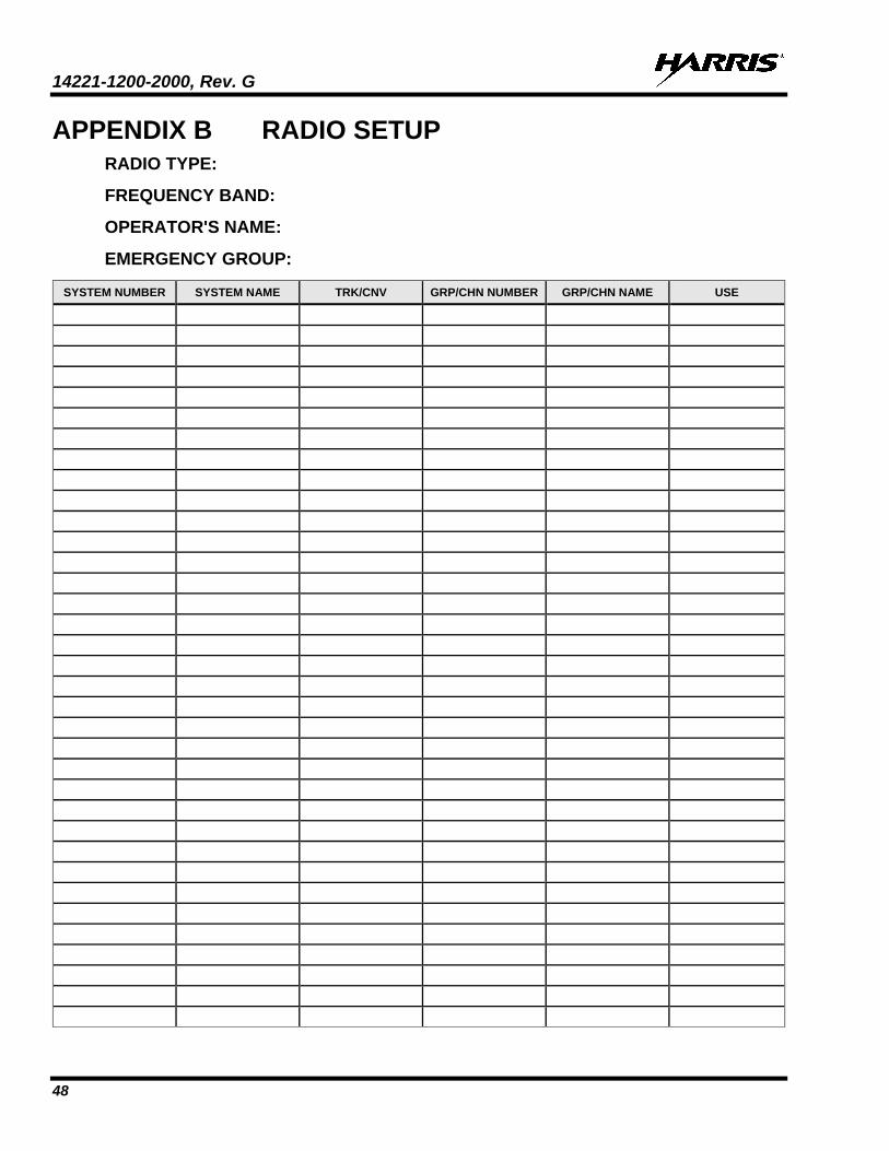
14221-1200-2000, Rev. G
48
APPENDIX B RADIO SETUP RADIO TYPE:
FREQUENCY BAND:
OPERATOR'S NAME:
EMERGENCY GROUP:
SYSTEM NUMBER SYSTEM NAME TRK/CNV GRP/CHN NUMBER GRP/CHN NAME USE

14221-1200-2000, Rev. G
49
SYSTEM NUMBER SYSTEM NAME TRK/CNV GRP/CHN NUMBER GRP/CHN NAME USE

14221-1200-2000, Rev. G
50
SYSTEM NUMBER SYSTEM NAME TRK/CNV GRP/CHN NUMBER GRP/CHN NAME USE

14221-1200-2000, Rev. G
51
SYSTEM NUMBER SYSTEM NAME TRK/CNV GRP/CHN NUMBER GRP/CHN NAME USE

14221-1200-2000, Rev. G
52
APPENDIX C PPP/SLIP CONNECTION C.1 OVERALL CONFIGURATION
This appendix describes how to setup PPP and SLIP connections between a Unity mobile radio acting as a Mobile Data Terminal (MDT) and a Mobile Data Peripheral (MDP). The MDP in Figure C-1 is a Windows XP machine. This example is used throughout the configuration, but is only intended as a guide. It is important to realize that all IP addresses are site/configuration specific. Prior to configuring the MDT or the MDP, the system administrator should provide configuration specifics.
RF IP10.1.101.209
Site1 IP10.1.101.27
Site2 IP10.2.101.27
Radio2 IP10.2.101.200
PPP IP10.1.101.209
PPP IP199.81.106.100
Public IP84.100.1.1
MDP Unity MDT IP Radio
Cable12082-0445-A1
Figure C-1: Example of PPP/SLIP Configuration
• MDP PPP IP Address – There are two types of configuration for the MDP’s IP address, dynamically assigned by PPP or statically assigned within the MDP’s PPP configuration settings:
Dynamic via PPP (shown in Figure C-1) - When using PPP’s dynamic IP address assignment, the radio will assign its own RF IP address to the MDP. Outbound IP data from the site will be processed by the radio if the port matches the ports within the radio’s services (Radio TextLink, OTAR, OTAP, etc.). All other outbound IP data from the site is forwarded to the MDP. Inbound IP data from the MDP will be processed by the radio if the MDP uses the radio’s PPP IP address; otherwise, it will be forwarded to the site.
Static – The MDP software allows the configuration of a static IP address to the MDP. While this provides more configurability, routing of traffic to the MDP from the site must be configured within the site’s routers.
• Unity MDT’s PPP IP – This is typically a nonce IP address (shown in Figure C-1) to allow the MDP to address the radio explicitly (i.e., ping).
• Unity MDT’s RF IP – This IP address is how the site addresses the radio and must match configuration at the site.
Other IP addresses in the figure above are beyond the scope of this configuration document and are provided for the configuration example only.

14221-1200-2000, Rev. G
53
C.2 RADIO CONFIGURATION 1. Use RPM to configure Unity MDT services, PPP IP address, and RF IP address.
2. Within Data Options Data Interfaces, enable MDT and configure the MDT’s PPP address:
3. Within the Data Options Data Transport, configure the MDT’s RF IP1.
C.3 MDP PPP CONFIGURATION (WINDOWS XP)
C.3.1 Windows XP Modem Configuration The following configures a modem that will be used for the PPP connection on a Windows XP Mobile Data Peripheral.
1. Open the Control Panel (StartSettingsControl Panel).
2. Select Phone and Modem Options.
3. Choose Modems tab.
4. Select Add button.
5. Choose “Don’t detect my modem; I will select it from a list.”
6. Choose Next >.
1 If the MDP will be configured to have the radio provide the IP address (dynamic PPP IP address assignment), it is important to set the RF IP Address even if the site will dynamically assign it. Otherwise, the radio will fail PPP negotiation until the radio has registered with the site.

14221-1200-2000, Rev. G
54
7. Choose the [Standard Modem Types] that corresponds the speed of the radio as configured in the RPM. For a 19200-bps connection, choose Standard 19200 bps Modem. By choosing a modem speed faster than the over-the-air bit rate removes the overhead incurred by PPP layer framing.
8. Choose Next >.
9. Choose the port to which the radio is connected.
10. Choose Next >.

14221-1200-2000, Rev. G
55
11. Windows will install the driver. Click Finish when completed.
C.3.2 Windows XP Dial-Up Connection The following configures a dial up connection to use the Windows XP Mobile Data Peripheral’s modem.
1. Open the Control Panel (StartSettingsControl Panel).
2. Open Network Connections.
3. Choose FileNew Connection.
4. When the wizard starts, choose Next >.
5. Choose Connect to the network at my workplace.
If this is the only data connection for this machine, choose Connect to the Internet instead.
6. Choose Next >.
NOTE

14221-1200-2000, Rev. G
56
7. Choose Dial-up connection.
8. Choose Next >.
9. Choose a Name for the connection. This is for informational purposes only and is the name that the connection will use within the Network Connection window. In this case, the radio name and the IP address assigned to that radio has been chosen as an indicator (XG-100M 10.1.101.209).
10. Choose Next >.
11. Choose a non-empty phone number for the connection.
12. Choose Next >.
13. Choose Do not use my smart card.
14. Choose Next >.
15. Choose Anyone’s use.
16. Choose Next >.
17. Choose Finish.
18. The following dialog is displayed:

14221-1200-2000, Rev. G
57
19. Choose either Cancel or Properties. If Properties is chosen, proceed with Section C.3.3, Configuring a PPP Dial-up Connection, step 3.
C.3.3 Windows XP PPP or SLIP Configuration
C.3.3.1 Configuring a PPP Dial-Up Connection
PPP connection is preferred over SLIP in most windows configurations as it allows for dynamic address assignment from the radio as well as frame validation.
1. Open the Control Panel (StartSettingsControl Panel).
2. Select the Dial-up connection that was just created.
3. Select FileProperties, and specify any Phone number2.
2 It is important to specify a Phone number: or XP will not start the connection process.
NOTE
Any phone number will do.

14221-1200-2000, Rev. G
58
4. Choose Configure. Verify that settings and baud rate match the RPM configuration for the radio.
5. Choose OK.
6. Choose the Options tab.
7. Deselect Prompt for name and password, certificate, etc. Deselect Prompt for phone number. Choose Idle time before hanging up: to be never. Select Redial if line is dropped.

14221-1200-2000, Rev. G
59
8. Choose the Security tab and verify the settings shown on the following screen.
9. Choose the Networking tab.
10. Choose the Type of dial-up server I am calling: to be PPP: Windows 95/98/NT4/2000, Internet. Deselect Client for Microsoft Networks.
11. Choose Settings located beneath the PPP:Windows 95/98/NT 4/2000, Internet selection.

14221-1200-2000, Rev. G
60
12. Uncheck all options.
13. Choose OK. The previous Networking tab properties window will be accessible again.
14. Select Internet Protocol (TCP/IP).
15. Choose Properties.
16. Select Obtain an IP address automatically unless the radio will be defining its own IP address. If
this is specified, it must match the PPP/SLIP address within RPM (often defaulted to: 199.81.106.100). Check with the system administrator regarding specifying a static IP address.
17. Choose Advanced.
Dynamic or
Use Unity MDT’s RF IP Address

14221-1200-2000, Rev. G
61
18. Deselect Use default gateway on remote network and deselect Use IP header compression.
19. Choose OK. The DNS and WINS tabs remain unchanged.
20. Choose OK to accept the IP address and advanced settings.
21. Choose OK to accept the Network Connections Properties.
C.3.3.2 Configuring a SLIP Dial-up Connection 1. Follow PPP connection setup through step 8.
2. Choose the Networking tab.
3. Select “Type of dial-up server I am calling:” to be SLIP: Unix Connection.

14221-1200-2000, Rev. G
62
4. Since SLIP does not allow dynamic address assignment, select Internet Protocol (TCP/IP) and choose Properties.
5. Specify the IP address after consulting with the system administrator.
6. Choose OK.
7. Choose OK.
C.3.4 Windows XP Route Configuration Notes 1. After the PPP has connected run the following commands:
The italicized IP address (i.e., 10.1.100.209) is the radio’s RF IP address as configured in RPM and the site. The bold IP address (i.e., 199.81.106.0) is a submask built off the radio’s PPP IP address.
a. route add 199.81.106.0 MASK 255.255.255.0 10.1.100.209 /p
b. ping 199.81.106.100 -n 1
2. Description of commands:
a. This route addition allows access to GPS over PPP. The RPM defaults to this nonce IP address. If RPM specifies something different, this will need to be updated. The “/p” makes the IP address permanent.
b. The ping should work.
NOTE
Unity MDT’s RF IP Address

14221-1200-2000, Rev. G
63
This page intentionally left blank.

About Harris Corporation
Harris Corporation is a leading technology innovator, solving customers’ toughest mission-critical challenges by providing solutions that connect, inform and protect. Harris supports government and commercial customers in more than 100 countries and has approximately $6 billion in annual revenue. The company is organized into three business segments: Communication Systems, Space and Intelligence Systems and Electronic Systems. Learn more at harris.com.
FLORIDA NEW YORK VIRGINIA BRAZIL UNITED KINGDOM UAE SINGAPORE