UNITED · UNITED Grooved Butterfly Valve Manually Gear Operated with Tamper Switch MODEL 2400-G...
8
UNITED Grooved Butterfly Valve Manually Gear Operated with Tamper Switch MODEL 2400-G INSTALLATION & MAINTENANCE MANUAL @@ LISTED APPROVED :/ % MSS-SP-67 300 PSI Working Pressure
Transcript of UNITED · UNITED Grooved Butterfly Valve Manually Gear Operated with Tamper Switch MODEL 2400-G...
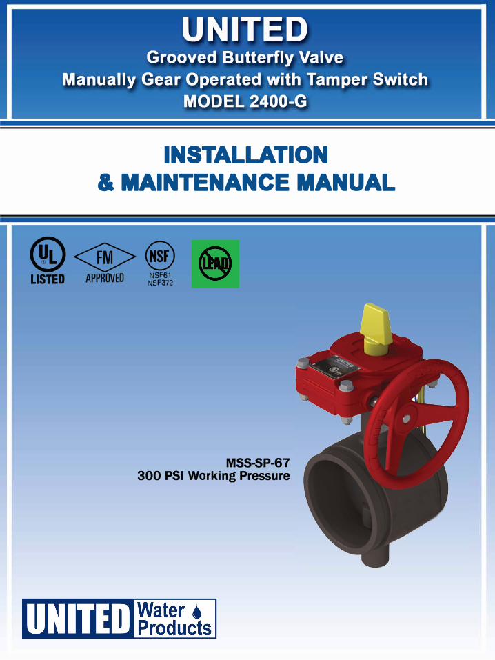
UNITED Grooved Butterfly Valve
Manually Gear Operated with Tamper Switch
MODEL 2400-G
INSTALLATION
& MAINTENANCE MANUAL
@<S>@ LISTED APPROVED :/ifs%
MSS-SP-67 300 PSI Working Pressure

1 of 6
Table of Contents
1. Product Overview…………………………………………………..………………………..2
1.1 Application…………………………………………….…….………………………..2
1.2 Product Feature……………………………………………….………………………2
2. Technical Parameters………………………………….…………………………………….2
2.1 Guiding Standards………………………………………………………………..…...2
2.2 Model Designation………………………………………………………….……..….2
2.3 Statement of Connection…………………………………….…………….……….…3
2.4 Material Specification……………………………………………………………...…3
3. Supervisory Switch……………………………………………………..………….….…….3
3.1 Power Instructions……………………………………………………….………..….3
3.2 Wiring Instructions…………………………………………………….…...…..…….3
3.3 Application Environment…………………………………………………………….4
4. Installation & Application……………………………………………………………....….4
4.1 Installation.…………………………………………………………….……………..4
4.2 Application…………………………………………………………….………..……5
5. Problems and Proposed Solutions……………………………………………..…..………6
6. Care & Maintenance………………………………………………………..…….….…….6

2 of 6
1. Product Review
1.1 Application:
UNITED Grooved Butterfly Valves are designed to be used as shut-off valves or throttling
valves in water supply, fire protection, and many other piping systems.
1.2 Product Features:
a) EPDM Encapsulated ductile iron disc for bubble-tight shut off
b) Flag type position indicator
c) Low torque operation
d) High cycle life
e) Built-in supervisory switch
f) Top flange to ISO 5211/1
g) Working Pressure: 2"~12": 300 psi
h) Working Temperature: 33°F to 176°F (0°C to 80°C
i) Fusion bonded epoxy powder coated to AWWA C550
j) UL Listed/FM Approved for indoor or outdoor use.
2. Technical Parameters
2.1 Guiding Standards:
2.1.1 Design Standards:
MSS SP-67 Butterfly Valves
2.1.2 Groove Dimension:
AWWA C606 Grooved and Shouldered Joints;
ISO 6182 Fire protection — Automatic sprinkler systems —Part 12: Requirements
and test methods for grooved-end components for steel pipe systems
2.1.3 Face to Face dimension:
MSS SP-67, Table 4;
2.1.4 Pressure Testing:
Tightness Test: 1.1 times of rated working pressure;
Shell Test:1.5 times of rated working pressure

3 of 6
Description Model No. Pressure
Rating Size Designation
WorkingTemperature
2400-G- ...... 300PSI 2" ~ 12" 0~-80℃
2.3 Statement of Connection
2.3.1 The valves are designed to be connected to the piping system with couplings;
2.3.2 The valves can be operated in lever handle, gear box, gear box with tamper switch,
electrical actuator, pneumatic actuator, etc.
2.4 Material Specification
Part No. Part Material Specification
1 Valve Body Ductile Iron ASTM A536, 65-45-12
2 Disc Ductile Iron ASTM A536, 65-45-12+EPDM
3 Stem SS431, 420, 304, 316, 416
2.2 Model Designation
Grooved ButterflyValve ManuallyGear Operated with Tamper Switch
3. Supervisory Switch
3.1
3.2
Power Instructions: 5A 250VAC
Wiring Instructions

3.3 Application Environment
Both indoor and outdoor.
4. Installation & Application
4.1 Installation
a) Check the system requirements, especially for operating pressure and temperature, and
ensure it is within the performance capability of the valve being installed.
b) Be careful when opening the packing crates to avoid damage to the valves and valve
parts inside. Inspect the contents carefully prior to use.
c) Inspect the grooves and gasket seats on the valves and adjoining pipes or fittings for
burrs, cracks, or other damage; and clear away any dirt or debris.
d) Thoroughly lubricate the coupling gasket and place over the adjoining pipe or fittings;
make sure that the gasket is with even tension around the pipe.
e) Make sure that the disc is in the closed position, so that debris cannot block the seating
surface of the valve.
f) Operate the valve to the full open and closed positions to check that it is functioning
properly.g) Proceed to install the valve in accordance with the following 7 step illustrated guide.
3. Supervisory Switch
3.1
3.2
Power Instructions: 5A 250VAC
Wiring Instructions
4 of 6

5 of 6
Connection of valve and
piping with gasketCoupling installation
Piping checking
Tightening of
bolts and nuts
Gasket checking and
lubrication
Installation completed
Install gasket

6 of 6
5. Problems and Proposed Solutions
Possible Problems Possible Causes Proposed Solutions
Sealing Surface
leakage
1. debris lodged in the waterway
around the seating area;
2. Sealing surface damaged;
3. Sealing surface worn out during
operation
1. Clear out the impurities;
2. Change valve seat;
3. Change valve seat;
Lever handle not
flexible or disc not
able to open or close
well.
1. Stem is damaged or there areimpurities around stem;
2. Stem is crooked;
1. Check the stem area and
remove the impurities;
2. Change for a new stem
6. Care & Maintenance
a) These valves should be stored in a cool and dry environment, with the two ends well
protected from entering of impurities; When the valves are in storage for more than 6
months, check every 6months the condition of the valves;
b) Disc of the butterfly valves are designed to be installed aligned with the diameter of
the pipelines. The discs are operated 0~90° axially around the stem, and when it turns
90°, the valves come to a fully open position.
c) For manual operation, the valve opens when operated anti-clockwise and the valve
closes when operated clockwise; for operation with electric actuator, need to follow
the instruction of the actuator.
4.2 Application
a) Make sure that the flow medium through the valve does not contain hard particles
which might cause damage to the sealing surface.
b) The valves should be handled carefully to avoid breakage and damage to the valve
parts.
c) Make sure that the disc is in the open position when doing piping system pressure test.
d) For butterfly valves with bypass, open the bypass first before opening the valve.
e) If the valve is heavy, prepare support first before installation