
United States standard for the colors of signal lights
40
National Bureau of Standards Library, N.W. Mdg SEP 8 1964 United States Standard for the Colors of Signal Lights Handbook 95 United States Department of Commerce National Bureau of Standards
Transcript of United States standard for the colors of signal lights

National Bureau of Standards Library, N.W. Mdg
SEP 8 1964
United States Standard for the
Colors of Signal Lights
Handbook 95
United States Department of Commerce National Bureau of Standards

HANDBOOKS OF THE NATIONAL BUREAU OF STANDARDS
The following Handbooks issued by the Bureau are available by pur¬ chase from the Superintendent of Documents, Government Printing Office, Washington, D.C., 20402, at the prices indicated:
No. Price 28 Screw-Thread Standards for Federal Services 1957, Part I (Amends in part H28
1944 and in part its 1950 Supplement)_ $1. 25 28 Screw-Thread Standards for Federal Services 1957, Part II_ . 75 28 Screw-Thread Standards for Federal Services 1957, Part III_ . 60 28 1963 Supplement, Screw-Thread Standards for Federal Services 1957 (Parts I,
II, and III)___ .70 30 National Electrical Safety Code_ 2. 25 44 Specifications, Tolerances, and Regulations for Commercial Weighing and
Measuring Devices—2d Edition_ 1. 25 48 Control and Removal of Radioactive Contamination in Laboratories_ . 20 49 Recommendations for Waste Disposal of Phosphorus-32 and Iodine-131 for
Medical Users_ . 15 51 Radiological Monitoring Methods and Instruments_ . 20 53 Recommendations for the Disposal of Carbon-14 Wastes_ . 15 55 Protection Against Betatron-Synchrotron Radiations up to 100 Million Electron
Volts_ .25 57 Photographic Dosimetry of X- and Gamma Rays_ . 15 58 Radioactive-Waste Disposal in the Ocean_ . 20 59 Permissible Dose From External Sources of Ionizing Radiation_ . 35 63 Protection Against Neutron Radiation up to 30 Million Electron Volts_ . 40 64 Design of Free-Air Ionization Chambers_ . 20 65 Safe Handling of Bodies Containing Radioactive Isotopes___ . 15 66 Safe Design and Use of Industrial Beta-Ray Sources_ . 20 67 Checking Prepackaged Commodities_ . 35 69 Maximum Permissible Body Burdens and Maximum Permissible Concentrations
of Radionuclides in Air and in Water for Occupational Exposure_ . 35 70 Tabulation of Data on Microwave Tubes_ 1. 00 71 Specifications for Dry Cells and Batteries_ . 25 72 Measurement of Neutron Flux and Spectra for Physical and Biological Applica¬ tions_ . 35
73 Protection Against Radiations From Sealed Gamma Sources_ . 30 74 Building Code Requirements for Reinforced Masonry_ . 15 75 Measurement of Absorbed Dose of Neutrons, and of Mixtures of Neutrons and
Gamma Rays_ . 35 76 Medical X-ray Protection up to 3 Million Volts_ . 25 77 Precision Measurement and Calibration
Vol. I. Electricity and Electronics_ 6. 00 Vol. II. Heat and Mechanics_ 6. 75 Vol. III. Optics, Metrology, and Radiation_ 7. 00
79 Stopping Powers for Use With Cavity Chambers_ . 35 80 A Manual of Radioactivity Procedures_ . 50 81 Safety Rules for the Installation and Maintenance of Electric Supply and Com¬
munications Lines_ 1. 75 82 Weights and Measures Administration_ 1. 75 83 Tabulation of Data on Receiving Tubes_ 1. 25 84 Radiation Quantities and Units (ICRU Report 10a)_ . 20 85 Physical Aspects of Irradiation (ICRU Report 10b)_ . 70 86 Radioactivity (ICRU Report 10c)_ .40 87 Clinical Dosimetry (ICRU Report lOd)_ . 40 88 Radiobiological Dosimetry (ICRU Report lOe)_ . 25 89 Methods of Evaluating Radiological Equipment and Materials (ICRU Report
lOf).. 35 90 Handbook for CRPL Ionospheric Predictions Based on Numerical Methods of Mapping_ . 40
91 Experimental Statistics_ 4. 25
(Continued on p. 3 of cover.)

UNITED STATES DEPARTMENT OF COMMERCE . Luther S. Hodges, Secretary
NATIONAL BUREAU OF STANDARDS • A. V. Astin, Director
United States Standard for the
Colors of Signal Lights
Prepared in Collabration with the
U.S. National Committee on Colors of Signal Lights
by
F. C. Breckenridge
National Bureau of Standards Handbook 95
Issued August 21, 1964
For sale by the Superintendent of Documents, U.S. Government Printing Office Washington, D.C., 20402 Price 25 cents

Foreword
Keliable recognition of signal light colors is an important factor in the safety of modern land, sea, and air transportation. With the growth of inter¬ national travel, the signal lights of each country are coming to be used more and more by the citizens of other countries, and a need for international standardization has become apparent. The U.S. Standard for the Colors of Signal Lights has been prepared as a recommended standard to help bring specifications used in this country for signal light colors into agreement with international usage as embodied in the recommendations of the International Commission on Illumination (CIE). This standard may also be expected to improve the specifications technically, eliminate wasteful differentiation, and contribute toward maximum reliability in signal-light recognition.
The U.S. Standard for the Colors of Signal Lights was developed by the U.S. National Committee on the Colors of Signal Lights under the sponsorship of the U.S. National Committee of the CIE. The National Bureau of Stand¬ ards cooperated in this effort by providing the technical data upon which the Standard is based. The Bureau is pleased to have the opportunity to increase the usefulness of the Standard by publishing it as an NBS Handbook.
A. V. Astin, Director.
Library of Congress Catalog Card Number: 64-60009
ii

Preface
This standard has been developed by the U.S. National Committee on
the Colors of Signal Lights under sponsorship of the U.S. National Committee
of the International Commission on Illumination. This committee is com¬
posed of representatives of the following organizations:
Government Agencies
Department of the Air Force
Headquarters U.S.A.F. Department of the Army
Transportation Materiel Command
Directorate of Engineering
Department of the Navy
Bureau of Naval Weapons
Bureau of Ships
Department of Commerce
National Bureau of Standards
Federal Aviation Agency
Systems Research and Development
Service
Interstate Commerce Commission
Treasury Department
U.S. Coast Guard
Associations
American Association of Motor Vehicle
Administrators Association of American Railroads,
Signal Section
Institute of Traffic Engineers
International Municipal Signal Association
Society of Automotive Engineers
Manufacturers
Corning Glass Works
E. I. du Pont de Nemours & Co.
Kopp Glass, Inc.
Rohm & Haas Company
January 1964.
m

Members of U.S. National Committee on Colors of Signal Lights
Name
January 1, 1964
Organization
J. F. Angier
J. A. Bartelt
Dr. F. W. Billmeyer, Jr.
J. J. Bouvier
F. C. Breckenridge
G. K. Clement
Jay Cohen
W. J. Cross, Jr.
Amos R. David
W. C. Fisher
Dr. D. B. Judd
Dr. C. E. Leberknight
W. F. Little
C. S. Michalski
B. G. Milster
V. J. Roper
S. Sease
K. W. Smith
LCDR E. R. Tindle
A. J. Werner
P. L. Wheeler
Secretary
Department of Navy, Bureau of Naval Weapons
E. I. du Pont de Nemours & Co.
Federal Aviation Agency, Air Navigation Facilities Chairman
Department of the Air Force
Department of Army, Office Chief of Transportation
American Association of Motor Vehicle Administrators
Department of Navy, Bureau of Ships
Federal Aviation Agency, Airport Systems Branch
National Bureau of Standards
Kopp Glass, Inc.
Electrical Testing Laboratories
Institute of Traffic Engineers
Interstate Commerce Commission
Society of Automotive Engineers
Rohm & Haas Company
International Municipal Signal Association
U.S. Coast Guard
Corning Glass Works
Association of American Railroads, Signal Section
Alternate
Prof. D. M. Finch Society of Automotive Engineers
Former members who participated actively in the preparation of the Standard
Name Organization
E. Boghosian
J. H. Dye
S. C. Kelton, Jr
F. J. Meno II
C. F. Peistrup
A. C. Webber
C. J. R. Taylor
Bureau of Ships
Department of the Army
Rohm & Haas Company
International Municipal Signal Association
U. S. Coast Guard
E. I. du Pont de Nemours & Co.
Association of American Railroads, Signal Section
rv

Abstract
The standard provides in part I basic chromaticity definitions defining
the chromaticities that are considered safe for use as representing the named
colors. These are the basis for the selection of the national standard filters
and for the tolerances given in part II for duplicating them. The procurement
requirements of parts III and IV are based primarily on sets of these filters
in combination with prescribed sources although provision is also made for
procurement under the basic chromaticity definitions in cases in which it is
impracticable to base the procurement on filters. Part V provides guidance
in selecting signal colors for new uses, and part VI provides methods for special
laboratory tests and serves as a technical interpretation of the practical tests
prescribed in parts III and IV.
v

Contents
Page
Foreword_ n
Preface_ in Committee_ iv Abstract_ v
I. Definitions underlying the specification of colors for light signals_ 1
II. Master specifications for standard filters for signal light colors_ 7
III. Specification for color of ware for use in producing signal light
colors_ 13
IV. Specification for color of signals produced with autochromatic
equipment_ 19
V. Use of colors for signal lights_ 23
VI. Procedures for the determination of the color of light signals by
referee laboratories_ 29
Throughout the text Roman numerals are used preceding the numbers of
figures, tables, and sections to indicate the part in which these will be found.
VI

Part I. Definitions Underlying the Specification of Colors for Light Signals
Introduction
Part I presents basic definitions for the chroma- ticities of the signal-light colors included in this standard. As a foundation for the definitive equations, which are stated in sec. 3, pertinent references are given in sec. 1 and general defini¬ tions in sec. 2. The chromaticity definitions are not to be considered as purchase specifications but as the boundaries within which procurement speci¬ fications are to be held. In addition to part I, procurement specifications will be necessary. Requirements for procurement are given in parts III and IV of the Standard.
1. Reference Publications
The publications cited below define the coordi¬ nate systems used in this standard and provide other information for the interpretation of the standard and the procurement specifications based upon it.
1. Proc. Intern. Comm. Ilium. (C.I.E.), Eighth Session, Compt. Rend., 1931, pp. 19-29.
2. The 1931 I.C.I. (C.I.E.) Standard Observer and Co¬ ordinate System for Colorimetry, D.B. Judd, J. Opt. Soc. Am., 23, p. 359 (1933).
3. Handbook of Colorimetry, A. C. Hardy, The Tech¬ nology Press, Massachusetts Institute of Tech¬ nology, Cambridge, Mass., 1936. Standard Observer is defined on p. 7 et seq.
4. Rectangular Uniform-Chromaticity-Scale Coordinates, F. C. Breckenridge and W. R. Schaub, J. Opt. Soc. Am., 29, p. 370 (1939).
5. The Psychophysics of Color, Committee on Colorim¬ etry, J. Opt. Soc. Am., 34, p. 245 (1944).
6. Quantitative Data and Methods for Colorimetry, Committee on Colorimetry, J. Opt. Soc. Am., 34, p. 633 (1944).
7. Tables for Transforming Chromaticity Coordinates from the I.C.I. System to the R-U-C-S System, NBS Letter Circ. LC-897, May 1948.
8. Colorimetry, NBS Circ. 478 (1950). 9. A Co-ordinated Specification for the Colours of Light
Signals, J. G. Holmes, Proc. Intern. Comm. Ilium. (C.I.E.) Eleventh Session (Paris) 1948, p. 512.
10. Proc. Intern. Comm. Ilium. (C.I.E.) Twelfth Session (Stockholm) 1951, 1, Sec. 26e; 3, pp. 70-73.
11. Spectrophotometry (200 to 1000 millimicrons), NBS Circ. 484 (1949).
12. The Science of Color, Committee on Colorimetry of the Optical Society of America (see esp. Definitions, p. 363) 1953.
13. Proc. Intern. Comm. Ilium. (C.I.E.) Thirteenth Ses¬ sion (Zurich) 1955, 1, Sec. 1.3.3.
14. Colours of Light Signals, Publication C.I.E. No. 2 (W-l.3.3) 1959.
2. General Definitions
The following technical terms are used through¬ out this standard in the senses in which they are defined in this section. (References are to sec. 1 above.)
2.1. Standard Observer and Coordinate System
The standard observer and coordinate system are those adopted by the International Commis¬ sion on Illumination (C.I.E.) at its Eighth Session at Cambridge, England, in 1931 (ref. 1, 2, 3). The coordinates x and y only are used in this standard. The standard observer is defined for cone vision and normal adaptation. Darkness adaptation with some inclusion of rod vision does not prevent correct recognition of colored lights if the luminance is sufficient for the light to be seen by a light-adapted observer.
2.2. Hue
Hue is that attribute of certain colors which determines whether the color is perceived as red, yellow, green, blue, purple, or as an intermediate color. Colors which have no hue are called neutral colors. A great variety of qualities of light are perceived as neutral under various cir¬ cumstances. In general, colors represented in the region of the C.I.E. chromaticity diagram near x=0.333, y=0.333 may be considered as neutral colors under ordinary conditions of observation.
2.3. Saturation
Saturation is that attribute of a color which determines whether the color is perceived as much or little different from neutral, the less prominent the hue, the lower the saturation.
2.4. Chromaticity
Chromaticity is the color-quality of a light as defined by its chromaticity coordinates which in turn are computed from the relative energy distri¬ bution of the light in accordance with procedures specified for each system of coordinates. (For the C.I.E. chromaticity coordinates, see ref. 1.) Chro¬ maticity is independent of the luminance, or other quantitative measure of the intensity of light being
1

observed. It correlates with hue and saturation, but since these are subjective quantities, they can not be measured, though they can be estimated with some reliability. Hue and saturation, how¬ ever, do vary with the luminance of the observed light and its background, and also with the color vision of the observer even when the relative energy distribution of the light itself remains the same. At a given luminance, the chromaticity of a light seen against a black background by a chro¬ matically normal observer determines its hue and saturation. Under favorable conditions, hue and saturation may be estimated by means of curves or tables from the coordinates (x,y or x",y"), but the relationship is neither simple nor exact. It is necessary to use the terms “hue” and “saturation” when referring to differences in the appearance of two colors, but, on account of the complex and approximate nature of the relationship of these quantities to the spectral energy distribution, it is preferable to express the precise results which may be computed from the relative spectral energy in terms of chromaticity coordinates.
2.5. Luminance
Luminance is luminous flux per unit solid angle emitted per unit projected area (ref. 12, p. 374).
2.6. Transmittance
Transmittance is the ratio of the luminous flux transmitted by the object to the luminous flux incident. (Properly this is “luminous trans¬ mittance”, but it is customary to use the short¬ ened form when no confusion can result.) (ref. 12, p. 374.)
2.7. Internal Transmittance
Internal transmittance is the ratio of the lumi¬ nous flux incident upon the second surface of an object to that transmitted by the first surface (ref. 12, p. 372).
2.8. Transmissivity
Transmissivity is the internal transmittance for a unit thickness of a nondiffusing1 substance (ref. 12, p. 384).
■ Note: The term “transmissivity” is also used for linear transmission through diffusing media.
2.9. Transmittance Ratio
Transmittance ratio is the ratio of the light flux transmitted by a test piece to the light flux trans¬ mitted within the same solid angle by a standard piece of the same design made from colorless material of a nature similar to that of the test piece. The light sources in the two cases must be essentially identical. Transmittance-ratio re¬ quirements are applicable to all ware, but espe¬ cially to ware that alters the candlepower distribu¬ tion (such as lenses or prisms). If the candlepower of a unit with colorless ware is multiplied by the
transmittance ratio, the product is approximately the candlepower to be expected with the test ware substituted for the colorless ware. For a plane filter, the transmittance ratio is equal to the internal transmittance, neglecting internal losses in the colorless filter used for reference.
2.1©. Color Temperature
Color temperature of a source is the temperature of a complete (Planckian) radiator having the same chromaticity as the source in question (ref. 12, p. 367). Color temperature is usually ex¬ pressed in degrees Kelvin (°K). The numerical value of a color temperature depends on the value assigned to C2 in Planck’s radiation equation for the complete radiator. For example, with the several values of C2 indicated the following values of color temperature T all represent the sam« spectral energy distribution.
a T 14320 2842 °K 14350 2848 °K 14380 2854 °Iv
In this standard, color temperature is expressed by nominal values given to the nearest 10 °K, based upon 672=14380.
2.11. Similar Chromaticity Characteristics
A light-transmitting material has chromaticity characteristics similar to a standard material for a given light source over a stated chromaticity range if the chromaticity coordinates, within that range, of the light from the given source trans¬ mitted by any thickness of the standard material can be duplicated within stated tolerances by the chromaticity coordinates of the light from the same source transmitted by some thickness of the subject material. As used in this standard and in specifications based upon it the phrase “similar chromaticity characteristics” will be understood to include the range of iiluminants to be used with the light-transmitting material in service, and the chromaticity range extends from the chromaticity of the applicable pale limit to that of the second hue limit, or to the chromaticity of such thickness of the subject material as has the minimum ac¬ ceptable transmittance, whichever gives the lesser range. In this standard the range of iiluminants is that specified in part II, table II—1; the minimum transmittance is that stated in table II—2; and the tolerance is that given in table II—3.
2.12. Color Standard
A color standard is a set of two or more filters in combination with a source of designated color temperature which together define one or more limits of acceptable chromaticity for the color represented and provide a basis for controlling the transmittance of ware which is to be used as the filter element of a signal light.
2

2.13. Basic Color Standard
A basic color standard is a color standard adopted by one, or a group, of the organizations which sponsor the U.S. Standard for the Colors of Signal Lights. The basic standards all include two or more filters having the same chromaticity characteristics for a designated range of color temperatures. With each is associated a set of minimum transmittance requirements. The ac¬ ceptable region of chromaticity of each standard is designed to provide limits for ware which will give a signal within the basic chromaticity defini¬ tion for the color represented when the ware is used with any source within a stated range of color temperatures.
2.14. Purchaser’s Color Standard
A purchaser’s color standard is a color standard adopted by a purchasing authority for a purpose which cannot be adequately accomplished with one of the basic standards.
2.15. Manufacturer’s Color Standards
A manufacturer’s color standard is a color standard submitted by a bidder and accepted by a procuring agency to control the purchase of ware to be furnished in accordance with a procure¬ ment specification on a stipulated order or con¬ tract. The chromaticity coordinates represented by a manufacturer’s standard should be de¬ termined by a laboratory equipped to make such determinations and approved by the procuring agency before the standard is accepted. Filters already furnished by the bidder, or his prospective subcontractor, to the agency requesting the bid, may be designated by a bidder as a manufacturer’s standard for a specific quotation.
2.16. National Standard Filter
A national standard filter is one of a set of filters adopted by the U.S. National Committee on Colors of Signal Lights to represent a basic color standard (2.13) and accepted by the National Bureau of Standards for reference and preservation as a national standard. The characteristics of the national standard filters are described in part II of the U.S. Standard.
2.17. Organization Standard Filter
An organization standard filter is one of a set of filters adopted by an organization which sponsors a basic color standard to represent that standard. Organization standard filters may be deposited with the National Bureau of Standards for refer¬ ence and preservation if they are acceptable to that Bureau.
2.18. Duplicate Standard Filter
A duplicate standard filter is a filter certified as having characteristics duplicating those of a
national or organization standard filter within the established tolerances stated in part II.
2.19. Working Standard Filter
A working standard filter is a filter adopted by a purchasing agency, a manufacturer, or a labora¬ tory to represent a chromaticity, range of cliroma- ticities, or a known transmittance.
2.20. Basic Chromaticity Definition
A basic chromaticity definition is a set of boundaries, expressed in terms of a recognized system of chromaticity coordinates, established to control the overall range in chromaticity of a stipulated class of signal lights.
3. Basic Chromaticity Definitions
3.1. General
The basic chromaticity definitions of this section have been adopted by one or by a group of the agencies which sponsor the U.S. Standard for Signal Light Colors. They are stated in the coordinates of the C.I.E. Coordinate System (ref. 2). Since this system does not represent chro¬ maticity differences uniformly, a parallel column has been included in each table giving the approxi¬ mately equivalent limits in the Rectangular- Uniform-Chromaticity-Scale system (ref. 4). In deriving these approximate equivalents, small deviations for both x" and y" have been allowed in some cases in order to keep the equations simple, but the maximum error in the left-hand side of the equation when true values are substi¬ tuted in the right-hand member will not exceed 0.0015.
3.2. Definition
A light is of the color named if the C.I.E. coordinates representing its chromaticity are within the boundaries stated for that color in table 1-1 which follows. The first color defined in each category is designated as signal red, signal yellow, etc., and contains all the chromaticities acceptable for any application coming within the province of this standard. For each of the colors except blue, further restriction is required for one or more applications and provision is made for this by giving the equation of the restricting boundary, and such boundaries are to be used in lieu of the corresponding general boundaries for applications which call for a more restricted range of chroma¬ ticities. The remaining boundaries of the more restricted colors are the same as the corresponding boundaries of the signal color. The symbols
and “<(” indicate the acceptable side of the boundary.
Figure 1-1 shows the boundaries of table 1-1 plotted in C.I.E. coordinates and figure 1-2 shows these boundaries in RUCS coordinates.
721-050—64- 3

Table 1-1. Basic chromaticity definitions*
Colors Standard Boundaries in C.I.E. Equations Approximate Equivalents in RUCS Equations
3.3 Signal Red Ax" =x" — 0.075 Purple boundary. - . _ _ x+y >0.992 *"2:+0.0725 Yellow boundary__ . . -- x-y^ 0.330 y" —0.317+0.16Az"
3.31 Intermediate Signal Red tPurple boundary - - x+y 2:0.992 *">+0.0725 Yellow boundary-- - x—y 2:0.380 y" 2= —0.375+ 0.4a*"
3.3.2 Restricted Signal Red Purple boundary---- x+y^ 0.997 *"> + 0.0741 Yellow boundary. _ x—y 2:0.405 2/"g—0.407 + 0.5A*"
3.4 Signal Yellow Red boundary_ — -- y >0.383 2/">-0.225-4Az" White boundary_ _ _ ___ x + y >0.872+0.200a: *"> + 0.068 - 0.0262/" Green boundary_ __ £ 2:0.550 y" ^—0.120+ 3Az"
3.4.1 Intermediate Signal Yellow fRed boundary.._ _ y >0.3S3 y" > —0.225 —4Az" fWhite boundary__ z+ y ^0.872+ 0.200a: *">+0.068-0.0262/"
y" jS —0.136 + 0.5Az" Green boundary__ x — y 2:0.124
3.4.2 Restricted Signal Yellow Red boundary. ._ _ ___ y> 0.400 2/">-0.194-4Az" fWhite boundary_ __ x+y ^0.872+ 0.200* z"2> +0.068-0.026?/"
y" g —0.136 + 0.5Az" Green boundary_ _ x—y/A 0.124
3.5 Signal Green Yellow boundary__ __ a; rSO.360 —O.OSOy *"< + 0.715?/" White boundary_ .. z ^0.650y y" > + 0.085-0.600*" Blue boundary- - y 2^0.390 — 0.171* *" ^ — 0.150Z/"
3.5.1 Intermediate Signal Green Yellow boundary . _ _ 2/^0.730(1-*) *" <+0.045 - 0.00 752/" fWhite boundary. _ .... .. __ x <0.650?/ y" > + 0.085-0.600*" Blue boundary ___ y 2:0.500 — 0.500* *"^-0.0202/"
3.5.2 Restricted Signal Green Yellow boundary_ ._ _ . y^ 0.730(1 -x) *"< + 0.045-0.00752/" White boundary_ . . _ x <0.425y y" >+0.142-0.450*" Blue boundary_ . _ _ . _ 2/^0.500-0.500* x" ^ —0.020?/"
3.6 Signal Blue Green boundary_... . _ . _ y <0.065 + 0.805* *"<-0.950y" White boundary___ . ... y ^0.400—* *"<-0.125 + 0.3502/" Purple boundary . ____ * ^0.100 + 0.700// y" 2: —0.370*"
3.7 Signal White Signal white includes all chromaticities whicl i qualify as any of the four whites de fined in sec. 3.7.1 to 3.7.4.
3.7.1 Variable Source White Green boundary____ 2/_2/o =0.003 2/o being the //-coordinate of the Purple boundary __ 2/o — t/ Si 0.003 Planckian locus at the point at
which *o is equal to *. Yellow boundary _ . . _ * <0.555 + 0.750(t/-0.405) y" 2: —0.1515 Blue boundary.._ . . ____ * 2:0.325 z" ^ —0.000 + 0.900(2/" —0.009)
3.7.2 Beacon White Green boundary . .. 2/ —2/o —0.003 2/o being the //-coordinate of the Purple boundary ._ ...... 2/o —2/ =0.003 Planckian locus at the point
at which *o is equal to * Yellow boundary____ *<0.490 + 0.500 (2/ —0.410) y" >-0.094+0.400 (z"-0.056) Blue boundary ... ._ . _ *2:0.325 z" 2: —0.000+0.900 (?/"-0.009)
*The recommended uses for the several colors are given in table V-l. tSame as for corresponding “signal” color. Note: An equation of the form:
y = a+b(x—c) is satisfied if x = c and y — a
In those cases in which the boundary definitions have been expressed with this type of equation, the constants a and c are the coordinates of a point close to the Planckian locus and approximate a critical point for the acceptance or rejection of a chromaticity. Since b is the slope, or the reciprocal of the slope, of the boundary (either Ay/Ax or Ax/Ay), any small correction necessary for an exact value is reduced to the form Ay = bAx or Ax — bAy.
4

Table 1-1. Basic chromaticity definitions—Continued
Colors Standard Boundaries In C.I.E. Equations Approximate Equivalents In RUCS Equations
3.7.3 Lunar White Green boundary.. _ _ _ _ ___ ?/<0.195 + 0.500* *" < + 0.016 —0.571y" Purple boundary _ __ y>0.170 + 0.500* *" >-0.002-0.586?/" Yellow boundary_ __ *<0.445+0.333 (y-0.405) y">-0.060 + 0.700 (*"-0.045) Blue boundary. __ . _ * 5:0.325 *"^+0.000+0.900 (t/" —0.009)
3.7.4 Blue White Green boundary
For*<0.330__ . . . y <0.030+* and y" < + 0.021-0.844*" For £>0.330_ y <0.195+0.500* *" < + 0.016 —0.571 y"
Purple boundary For *<0.330._ . ... y ^0.005+* or y" i> +0.004 — 0.794*" For £>0.330 y >0.170+0.500* *" >-0.002-0.586y"
Yellow boundary.. _ *<0.445 + 0.333 (t/-0.405) y">-0.060 + 0.700 (*"-0.045) Blue boundary__ _ *>0.265-0.250 (y—0.280) *">-0.037 + 0.700 (?/" —0.040)
5

Figure 1-2
6

Part II. Master Specifications for Standard Filters for Signal Light Colors
1. Scope and Classification
1.1. Scope
This master specification contains the require¬ ments for limit filters which in combination with designated light sources constitute the basic color standards for signal-light colors.
1.2. Classification
1.2.1. Types of Filters. Four types of standard filters are recognized in this specification, namely:
National standard filters Organization standard filters Duplicate standard filters Working standard filters
These are defined in part I of the U.S. Standard for the Colors of Signal Lights as follows:
2.16. National Standard Filter
A national standard filter is one of a set of filters adopted by the U.S. National Committee on Colors of Signal Lights to represent a basic color standard (2.13) and accepted by the National Bureau of Standards for reference and preser¬ vation as a national standard. Their characteristics are described in Part II of the U.S. Standard.
2.17. Organization Standard Filter
An organization standard filter is one of a set of filters adopted by an organization which sponsors a basic color standard to represent that standard. Organization stand¬ ard filters may be deposited with the National Bureau of Standards for reference and preservation if they are acceptable to that Bureau.
Those presently so deposited are described in the appendix to part II, table II—6.
2.18. Duplicate Standard Filter
A duplicate standard filter is a filter certified as having characteristics duplicating those of a national or organiza¬ tion standard filter within the established tolerances stated in part II.
2.19. Working Standard Filter
A working standard filter is a filter adopted by a pur¬ chasing agency, a manufacturer, or a laboratory to repre¬ sent a chromaticity, range of chromaticities, or a known transmittance.
1.2.2. Colors. The requirements of this specifi¬ cation apply to standards for the following colors:
Red Signal red Intermediate signal red Restricted signal red
Yellow Signal yellow Intermediate signal yellow Restricted signal yellow
Green Signal green Intermediate signal green Restricted signal green
Blue Signal blue
White Signal white Variable-source white Beacon white Lunar white Blue white
2. Applicable Documents
Part I of the U.S. Standard for the Colors of Signal Lights contains definitions applicable to this specification.
National Bureau of Standards Circulars 478 (Colorimetry) and 4S4 (Spectrophotometry) con¬ tain information with reference to chromaticity testing that is applicable to this specification.
3. Requirements
3.1. Composition of Standards
Each color standard consists of a set of two or more filters and an illuminant of designated color temperature (part I, 2.12). One filter designated as the “pale-limit” represents the minimum color¬ ation that is acceptable. In general this filter is both a hue limit and a saturation limit. In the cases of yellow and green, it is necessary to have a second hue limit. In all cases, at least one filter designated as a “transmittance standard” is provided to serve as a basis for measuring the transmittance of ware that is near the minimum acceptable transmittance for its grade. The same filter may be designated as both a chroma¬ ticity limit and a transmittance standard if it meets the requirements for both.
7

Table II—1. Range of light-source color temperatures for determining compliance with similar chromaticity require¬ ments
°K ((72 = 14380)
Aircraft Lights: Formation lights.. Indicator lights... Instrument lights. Position lights....
2100-2300 1800-2300 1800-2300 2500-2800
Aviation Ground Lights: Approach lights_ Beacons_ Code beacons... Course lights_ Obstruction lights__ Runway and threshold lights:
Low intensity_ Medium intensity_ High intensity_
Traffic projectors, portable_
1550-3250 2850-3000 2850-3000 2850-3000 2100-2850
1550-3100 1550-3100 1550-3100 2350-2850
Automotive Signals: Brake lights_ Tail lights.— Turn signals_
2950-3150 2350-2600 2350-2850
Highway Traffic Lights: All types.. 2350-2850
Marine Lights: Lights, acetylene- Lights, battery operated. Lighthouses, electric power... Post lanterns, electric power.. Ships running lights, electric.. Ships running lights, kerosene.
2360 1900-2350 2850-3000 2350-2850 1900-3050 1900-2100
Railroad Signals: Electric Power, pressed ware_ Battery Operated, pressed ware.. Oil Wick Flame, pressed ware... Electric Power, polished disk_ Battery Operated, polished disk. Hand Lanterns, Oil Wick Flame.
2350-2850 1900-2350 1900-2100 2350-2850 1900-2350 1900-2100
Table II—3. Tolerances for similar chromaticity characteristics
The following table contains the tolerances for similarity of chromaticity as defined in 1-2.11. In this table Ax, Ay, Ax", and Ay” are the numerical values (neglecting the sign) defined by the equations:
Ax=x —x0, for y = yo Ay=y — t/o, forx=x0
Aa"=x"— x0", for y"—yf Ay"=--y"-yf, forx"=x0"
in which Xo and yo (also xf and y0") are the coordinates of the chromaticity of light from a souice of the specified color temperature transmitted through any thickness of the standard material, within the required chromaticity range, and x and y (also x" and y") are the coordinates of the chromaticity of the same light transmitted through the optimum thickness of the mateiial under consideration.
Color
Limits Approximate Equiva¬ lents
Ar max Ay max Ax” max Ay''max
Red__ 0.0015 .002 .010
0.0005 .0007 .004
Yellow_ Green_ ... Blue___ 0.010 0.014
Table II-2. Minimum transmittance values for determining compliance with similar chromaticity requirements Illuminant is 2854 °K
For aeronautical and marine standards
A.
B
C.
D
Grade Signal red
Signal yellow
Signal green
Signal blue
0.184
.161
.138
.120
0.652
.460
.368
.276
0. 207
.184
.161
.138
0.024
.020
.015
.007
E.
F.
G.
H.
Grade
{
Note. In general the several grades are considered suitable for the follow¬ ing uses:
A—For ware in which the highest possible transmittance is essential. B—For pressed ware of uniform thickness not more than 6 mm (0.2 in.)
throughout the working area. C—For blown ware. D—For thick-sectioned pressed ware. E—For thin cones and polished disks to be used in searchlight-type
signals.
3.2. Similarity of Material
All the filters of a standard shall have similar chromaticity characteristics (part 1,2.11), table 11-3.
3.3. Ranges of Illuminants
In qualifying filters for standards, the ranges of color-temperature given in table II—1 will be assumed for the illuminants in the lighting units indicated.
3.4. Range of Transmittance
In qualifying filters for standards, the ranges of transmittance given in table II-2 will be
For railroad and highway standards
lestr. red
Interm. red
Interm. yellow
Signal yellow
Interm. green
Signal blue
Lunar white
0. 064 0.183 0.021
.047 0.127 0.300 .200 .021 f 0.290 1 k . 162
.047 .095 0.440 .200
.078 )_ .452 .169 .0169 « . 079 /
F—For lenses, roundels, and slides for wayside signals and train markers. G—For traffic signal cover glasses. H—For lantern globes, generally blown ware. k Alternate for kerosene illuminant. « Alternate for electric lanterns.
(See table V-3 for antecedent specifications)
assumed according to the application of the standard.
3.5. Chromaticity
No standard shall be qualified unless it is feasible to produce ware having chromaticity character¬ istics similar to its paler limit and also a transmit¬ tance equal to the minimum permissible for the grade of ware to be furnished under the standard, and the chromaticity of such ware shall remain within the boundaries of the appropriate basic chromaticity definition of table I—1, for the applicable range of illuminants as given in table II—1, and the applicable variation m transmittance allowed in table 11-2.

Each standard shall contain at least one filter, to be used as a transmittance standard, which shall conform to the following additional chroma¬ ticity requirements with illuminant 2854 °K:
Color Limit
red y<0.310 yellow y<0.435 green £<0.210 blue y<O.OS6
This requirement is for the purpose of insuring that the chromaticity difference between minimum transmittance ware and the transmittance stan¬ dard will not be so great as to interfere with check¬ ing the acceptability of the ware for transmit¬ tance.
3.6. Physical Requirements
3.6.1. Material. Standard filters shall be made of material similar to that from which the ware is to be made (part I, 2.11).
3.6.2. Uniformity of coloring. The coloration shall be uniformly distributed throughout the material. Flashed material consisting of a thin layer of highly selective material attached to a clear body shall be avoided.
Note: This is not only because of probable nonuni¬ formity from spot to spot but also because slight scratches may alter the chromaticity significantly.
3.6.3. Dimensions. The standard filters shall be cut square, not more than 5.05 centimeters (1.99 in.) nor less than 4.90 centimeters (1.93 in.) on each side, and shall not be less than 1.5 milli¬ meters (0.059 in.) thick.
Note: These dimensions are required in order to make the various standard filters applicable to testing equip¬ ment already available. The minimum thickness is to avoid unduly fragile standards.
3.6.4. Optical quality. Standard filters shall have sufficiently plane, parallel, and well-polished faces, and shall be sufficiently free from bubbles, striae, scratches, and other defects to be suitable for use as standards. Any defect sufficient to alter appreciably the judgment of an inspector in his use of the specimen as a standard shall be avoided.
3.7. National Standard Filters
The national standard filters that have been adopted by the U.S. National Committee on the Colors of Signal Lights are listed in table II-4 and their chromaticities for five illuminants are listed in table II—6 (appendix).
3.8. Duplicate Standard Filters
Duplicate standard filters shall have similar chromaticity characteristics 'within the tolerances given in table II—3, to the national standard filters which they represent for the applicable range of color temperatures listed in table II—1
Table II-4. Tolerances for duplicates of national standard filters
Illumlnant 2854 °K
x, y, coordinates uplicate; xo, yo, coordinates of standard; Ax=x —xo, Ay—y — yo
Red Filters
For all red filters one lateral boundary is the spectrum locus and the other is: xf-yf^O.9995. All terminal boundaries have slope Ay/Ax=l. Location of terminal boundaries is fixed by defining tolerance on line x+y= 1.0000.
Tolerances Chromaticity with for min. Ay
2854 °K source for max. Ay Filter
Chromaticity definition in part I Purpose of standard No. Accepted value
>
<Ci II 1 o
JO Vo
Restricted (special)_ Trans, std_ 3.086T 0. 7224 0. 2776 Ay=-0.0025 Ay=+ .0010
Restricted (special)...__ Yellow limit_ 3.154 .7132 .2867 Ay = — .0010 Ay=+ .0007
Restricted_ Trans, std.. 3.154T .7132 .2867 Ay=- .0030 A y=+ .0007
Restricted.___ Yellow limit_ 3.126 .7050 .2949 Ay = — .0010 Ay=+ .0005
Intermediate__ 3.126T .7050 .2949 Ay=- .0035 Ay = + .0005
Intermediate_ Yellow limit__ 3.075 .6927 .3072 Ay = - .0010 Ay=+ .0005
Signal_ Trans, std. 3.075T .6927 .3072 Ay=- .0040 Ay=+ .0005
Signal..___ Yellow limit ... - 3.640 *.6687 •. 3310 Ay = — .0010 Ay=+ .0010
•Replacement for 3656A, values to be adjusted when measurements have been completed, see corrigendum.
9

Table II-4. Tolerances for duplicates of national standard filters—Continued
Yellow Filters
For all yellow filters one lateral boundary is spectrum locus and the other is given in table as min (xf-y) = const. All terminal boundaries have slope AylAx—1. Location of terminal boundaries is fixed by defining tolerance on lines x+2/=x0+l/o.
Chromaticity definition, part I Purpose of standard Filter No.
Chromaticity with 2854°K source
Toler¬ ance for
min (z+y)
Tolerance at x+y=xo+yo
Accepted value (z+y) Min Ay Max Ay
10 yo
Signal and intermediate_ Red limit*.. 4.200 4.199 4.160 4.261
0.5889 .5762 . 5635 .5515
0. 4073 .4226 .4349 .4454
0.9960 .9975 .9970 .9965
-0.0005 -.0010 -.0010 -.0025
+0.0015 +. 0010 +.0010 +. 0003
Restricted___ Red limit*-.,.. Restricted and intermediate_ Green limit_ _ Signal_____ Green limit___
*Ked limits also serve as transmittance standards.
Green Filters
Chromaticity with 2854 °K source
Tolerance* for min x for max x
Tolerance* for min y for max y
Chromaticity definition, part I Purpose of standard Filter No. Accepted value S
|
1 H 1
il |
< Ay=y—yo
Xo yo Ax Ay
Signal and intermediate__ _ __ _ _ Yellow limit_ . _ ___ 7.134 0.2448 0. 4145 -0. 0015 -0. 0010+0. 25AX +. 0010+0. 25AX -.0020+0.3Ax +. 0010+0.3AX
0020+0. 5AX +. 0020+0. 5AX —. 0020+0. 6AX +. 0020+0. 6Ax -. 0020+0. 8Ax +. 0020+0.8Ax
Signal and intermediate--- ___ _ Yellow limit__ _ _ __ 7.137 .2324 .4116 +.0015 -.0015
Yellow limit blue__ _ _ 7.087 .2084 .4016 +.0015 -.0020
7.322 . 1909 .3891 +.0020 —.0015
Signal_ ____ __ __ __ __ Blue limit ___ 7.136 .1753f ,3795t +.0015 -.0015 +. 0015
Blue limits also serve as transmittance standards. *For diagram interpreting equations, see figure II-l. The constants given in the columns headed Ax and Ay are represented in the figure by Cx, Cs, Kx, and K„. The coefficients of the Ax terms are the mv
ratios of the figure. fNew standard, values to be adjusted when measurements have been completed, see corrigendum.
Blue Filters
Filter
Chromaticity with 2854 °K source
Tolerance* for min x for max x
Tolerance* for min y for max y
Chromaticity definition, part I Purpose of standard No. Accepted value Ax=x—Xo Ay=y—yo
Xo yo Ax Ay
Green and white limit-___ 8.047 0.1530 0.1221 -0.0010+0. 25Ay +. 0010+0. 25Ay -. 0010+0.25Ay +. 0010+0. 25Ay —. 0005+0. lOAy +. 0020+0. lOAy -. 0010+0. lOAy +. 0010+0. lOAy
-0.0025-0.25Ax
Green and white limit__ __ __ _ 8.141 . 1575 .1212 +. 0005-0.25AX -.0030-0. 25Ax
Trans, std______ __ 8.057 . 1440 .0862 +. 0010-0. 25AX -.0100-0. lOAr
Trans, std___ _ __ 8.131 .1474 .0728 +. 0020-0.10AX -.0020-0.10Ax +. 0100-0. lOAx
"For diagram interpreting equations see figure II-l. The constant terms listed in the columns under Ax and ay are shown in the diagram as Cx, C„, Kx, and K,, and the coefficients of Ay and Ax are shown as mx and mp, respectively.
10

Figure II—1
Table II-5. Computed values for critical points of tolerances for national standard filters*
Illuminant 2854 °K
3.086T.
3.154„
3.154T.
3.126..
3.126T.
3.075..
3.075T.
3.640.. .
Red filters, intercepts at j-H/=1 Yellow filters, intercepts at x+y=xo+vo
Filter No. Apparent value
X y
0. 7249 0. 2751 . 7214 .2786 . 7143 .2857 . 7126 . 2874 .7163 . 2837 . 7126 . 2874 . 7061 . 2939 .7046 .2954 .7086 .2914 .7046 .2954 . 6938 .3062 .6923 .3077 .6967 .3032 .6922 .3077 .6697 .3300 .6677 .3320
Filter No. Apparent value
Min y Max y
4.200_ 0.4068 .4216 .4340 .4429
0.4088 .4236 .4360 .4457
4.199__
4.261___
Jo and yo are chromaticity coordinates for the National Standard Filter,
•These values are given to facilitate comparison with antecedent specifica¬ tions. They are computed on the basis of the currently accepted values for the national standard filters. Should any occasion arise to revise the values assigned for the coordinates of any of these filters the corresponding values in this table would have to be changed accordingly.
Apparent values at tolerance corners
Green filters Blue filters
Filter No. X Max y X Max y Filter No. Min i Max y Max x Max y Min y Min y Min x Min y Max x Min y
7.134_____ 0. 2433 0. 4151 0.2463 0.4159 8.047__ 0.1522 0.1228 0.1541 0.1223
. 4131 . 4139 . 1515 .1200 . 1534 . 1195 .1568 . 1224 .1587 . 1219
7.137.... .2309 . 2339 8.141 . .4092 .4100 .1559 . 1186 .1577 . 1181
7.087_ .2064 .4026 . 2104 .4046 8.057 _ .1437 .0882 . 1462 .0880
.3986 . 4006 .1425 .0764 . 1450 .0761
7.322.... . 1894 .3902 . 1924 .3920 8.131 __ . 1474 .0828 . 1494 .0826
.3862 .3880 . 1462 .0709 .1482 .0707
7.136.....
721-050—64- -3
11

and transmittances listed in table II—2, and they shall conform in chromaticity and transmittance to the applicable tolerances stated in table 11-4. (See also table II-5.)
3.9. Approval of Working Standards
It is important that the filters of a standard be made from the same type of material as is to be used for the manufacture of ware to be controlled by the standard. In cases where an established practice does not exist, manufacturers should ascertain in advance of bidding whether or not the material they desire to use in supplying ware on any contract which they may receive under any procurement specification based on the U.S. Standard for the Colors of Signal Lights has simi¬
lar chromaticity characteristics to those of the primary standard filters described in tables 3 and 4. If the proposed material does not meet this requirement, the manufacturer may, with the consent of the purchasing agency, submit duplicate sets of limit filters to that agency with the request that such filters be tested and if found satisfactory be accepted as a working standard for that con¬ tract. If found satisfactory, one of the duplicate sets will be returned to the manufacturer and the other will be delivered to the inspection staff of the purchasing agency.
Note: If new standards for plastics are required they will be added to table II-4. In the meantime sec. 3.9 is available to provide for their present uses.
Appendix
Table II-6. Organization standard filters
The filters listed below have been deposited with the National Bureau of Standards by the Signal Section of the Association of American Railroads. Those identified by 4 digit numbers with a decimal point have been adopted as national standard filters, the others have the status of organization standards. The chromaticity and transmittance values given below for source color temperatures 1904 °K, 2365 % and 2854 °K are from NBS Research Paper RP1688.
Filter no. Illuminant 1500 °K Illuminant 1904 “K Illuminant 2365 °K Illuminant 2854 °K Illuminant 3250 °K
X V T X V T X V T X V T X V T
Red: 3.075___ 0. 7000 0.2999 0.3084 0.6967 0.3032 0. 2431 0.6944 0. 30.55 0.1989 0. 6927 0. 3072 0.1698 0.6917 0. 3082 0.1538 3.086_ .7241 .2759 .1337 .7234 .2766 . 0944 .7228 .2772 .0711 . 7224 . 2776 . 0572 .7223 .2777 .0499 3.126_ .7094 .2905 .2711 . 7074 . 2925 .2072 .7060 . 2940 . 1655 .7050 .2949 .1388 . 7044 . 2955 . 1244 3.154___ . 7161 .2839 .2106 .7148 .2852 .1564 .7138 .2862 . 1222 .7132 .2867 .1009 .7128 . 2872 .0895
Yellow: 4.199_ .6238 . 3754 .7632 .6036 .3955 .7137 . 5878 .4111 .6692 .5762 .4226 .6334 .5692 .4295 .6106 4.200_ .6329 .3661 .7295 .6147 .3836 .6708 .6000 .3972 .6210 .5889 .4073 .5823 . 5820 . 4133 .5584 4.261.. ... . _ .6127 .3859 .7998 .5873 .4107 .7669 .5669 .4306 .7358 .5515 .4454 .7095 .5422 . 4545 .6922
Green: 7.087__ .3217 .5366 . 1150 . 2684 . 4976 .1492 .2316 .4472 .1784 .2084 .4016 .2013 .1965 .3719 . 2155 7.134_ .3798 .5164 . 1699 .3197 .4944 .2106 .2749 . 4550 .2442 . 2448 .4145 .2698 .2286 . 3866 .2856 7.137___ .3610 .5245 . 1487 .3025 .4974 . 1872 .2602 . 4542 . 2193 .2324 .4116 .2440 .2175 .3828 .2592 7. 322___ .2896 .5437 .0928 .2415 .4942 . 1236 .2099 .4376 . 1502 .1909 .3891 .1712 .1813 . 3586 .1845
Blue: 8.047__ . 2328 .2915 .0157 . 1783 .2049 .02216 . 1595 . 1521 .02909 . 1530 .1221 .03556 . 1510 . 1070 .0401 8.057..__ .1590 .2029 .0072 . 1458 .1387 .01164 .1436 . 1051 .01669 . 1440 .0862 .02155 . 1447 .0770 .0251 8.131_ .1830 .1788 .0056 . 1543 . 1187 .00876 . 1482 .0889 . 01252 . 1474 .0728 . 01626 . 1476 .0649 . 0190 8.141_ .2610 . 2945 .0160 .1916 .2070 .02173 . 1665 .1522 .02789 . 1575 .1212 . 03372 . 1545 .1058 .0378
Filter no. Illuminant 1500 °K Illuminant 1904 °K Illuminant 2365 °K Illuminant 2854 °K Illuminant 3250 °K
X y T X y T X y T X V T X y T
Red: 126_ 0. 7094 0. 2905 0. 2711 0. 7074 0. 2925 0. 2072 0. 7060 0. 2939 0.1655 0. 7050 0. 2949 0.1389 0. 7044 0.2955 0.1244 201_ .7074 .2926 .2862 . 7051 .2948 .2205 .7036 .2963 .1771 .7025 .2974 . 1493 .7018 .2981 . 1340 211_ .7189 .2811 . 1778 . 7178 .2822 .1300 .7171 .2829 . 1004 . 7165 .2835 .0823 .7161 .2838 .0726 400__ .7125 .2875 .2515 .7108 .2891 .1898 .7096 .2904 . 1502 .7088 .2912 .1251 .7083 .2917 . 1116
Yellow: 141__ .6221 .3748 .5901 . 5963 .3976 . 5571 . 5740 .4157 .5296 .5560 .4291 . 5082 . 5445 . 4370 .4949 142... . 6326 .3658 .4609 .6113 .3861 .4262 . 5934 .4026 .3978 .5794 .4151 .3762 .5705 .4228 .3629 271_ .6328 .3667 .7029 .6151 .3843 .6456 .6014 .3979 . 5967 .5913 .4078 .5584 .5853 .4138 .5346
Green: 139_ .4001 .5141 .1640 .3407 .5025 .2002 .2951 .4721 .2294 .2634 .4376 .2515 .2458 .4126 .2649 140_ .3494 .5385 .1099 .2949 .5138 . 1397 . 2555 .4742 . 1645 .2295 .4348 . 1835 .2154 .4078 . 1952
Lunar white: 45 . 5259 .4029 .2041 .4395 .3981 . 2173 .3651 .3664 . 2306 . 3122 .3279 .2421 .2832 .3004 .2497 73_ .5361 .4030 . 2505 .4556 . 4032 .2643 . 3840 . 3772 .2779 .3308 . 3426 .2895 .3007 .3166 .2972 74_ .5024 .3958 .1285 .4005 . 3766 .1394 .3216 . 3308 . 1509 .2711 .2852 . 1612 .2456 . 2559 .1682 124_ .5520 .4027 .3614 .4822 .4106 . 3755 .4169 .3953 .3891 .3654 .3688 .4004 .3346 . 346S .4077
Yellow: * 359_ .6093 .3887 .7856 .5822 .4148 .7590 .5601 .4358 .7334 .5432 .4517 .7115 .5329 .4614 .6970
•Deposited by Institute of Traffic Engineers.
12

Part III. Specification for Color of Ware for Use in Producing Signal Light Colors 1
1. Scope and Classification
1.1. Scope
This specification defines the color requirements for light-transmitting ware. Equipment in which the coloring element and the light source are inseparable is not included.
1.2.3. Classes. This specification covers trans¬ mittance requirements for two classes of ware.
1.2.3.1. Refracting ware. Refracting ware is ware intended to alter significantly the candle- power distribution of the light source.
1.2.3.2. Nonrefracting ware. Nonrefracting ware is ware which is not intended to alter the candlepower distribution of the source signif¬ icantly.
1.2. Classification
1.2.1. Colors. The following colors are in¬ cluded in this specification:
Signal red
Signal yellow
Signal green
Signal blue Signal white
Intermediate signal red
Intermediate signal yellow
Intermediate signal green
Variable source white
Beacon white
Restricted signal red
Restricted signal yellow
Restricted signal green
Lunar white Blue white
1.2.2. Grades. This specification covers the transmittance requirement of eight grades of light-transmitting ware designated as grades A through H.
2. Applicable Specifications and Publications
2.1. U.S. Standard
Parts I, II, and V of the U.S. Standard for Colors of Signal Lights are applicable to this specification.
3. Requirements
3.1. Transmittance
The transmittance ratio or apparent trans¬ mittance 2 of the ware shall not be less than the appropriate value given in table III—1 for the class and grade of ware stipulated. If neither the detail drawings, the equipment specifications,
Table III—1. Minimum transmittance values for different grades of ware
Uluminant is 2854 °K
For aeronautical and marine standards
Grade Signal red
A B
C D
0.184 .161
.138
. 120
Signal yellow
0.552 .460
. 36S
.276
Signal green
0.207 .184
.161
.138
Signal blue
0.024 .020
.015
.007
Grade
For railroad and highway standards
E.
F.
G
H
Eestr. red
0.064
.047
.047
.078
.079e
Interm. red
0.127
.095
Interm. yellow
0.300
.452
Signal yellow
0.440
Interm. green
0.183
.200
.200
.169
Signal blue
0.021
.021
.0159
Lunar white
0.290 .162k
Note. Unless otherwise stipulated in this specification or in the procure¬
ment order, the several grades are applicable to the following types of ware:
A, For ware in which the highest possible transmittance is essential.
B, For pressed ware of uniform thickness not more than 6 mm (0.2 in.) throughout the working area.
C, For blown ware.
D, For thick-sectioned pressed ware.
* This specification may be used as a procurement specification or the pertinent sections may be revised as required and incorporated into a speci¬ fication for equipment. Procurement orders should state the color and grade, and may also state the national standard or organization standard filters to be used as hue limits. In any case, color and grade designations should be consistent with this specification.
E, For thin cones and polished disks to be used in searchlight-type signals.
F, For lenses, roundels and slides for wayside signals and train markers. G, For traffic signal cover glasses. H, For lantern globes, generally blown ware, k, Alternate for kerosene illuminant. e, Alternate for electric lanterns.
(See table V-3 for antecedent specifications.)
2 For a discussion of the relationship between “apparent” and “true" transmittance, see footnote to sec. 4.6.3.2.
13
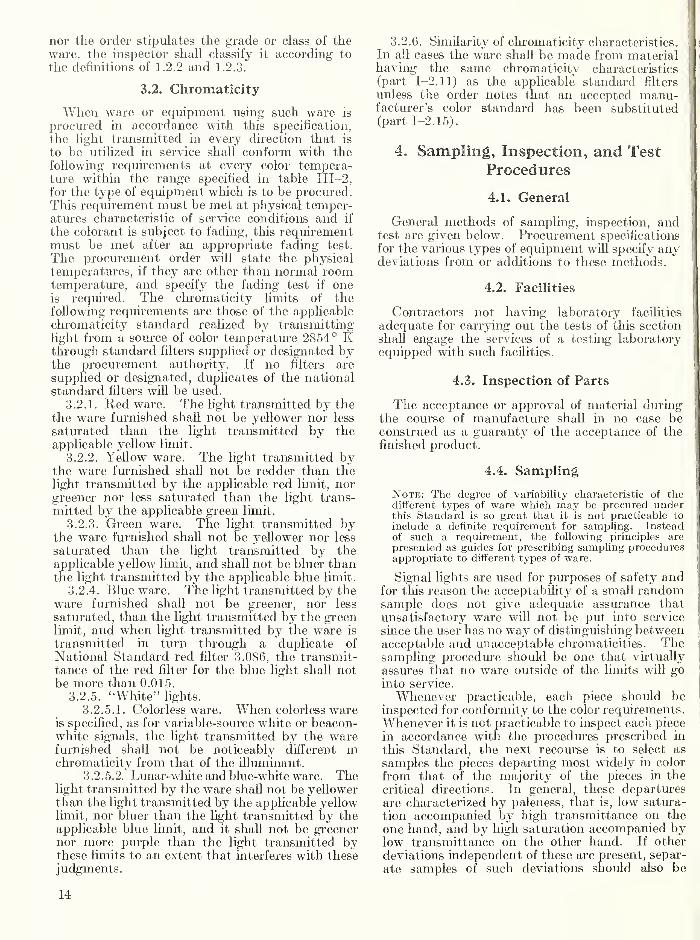
nor the order stipulates the grade or class of the ware, the inspector shall classify it according to the definitions of 1.2.2 and 1.2.3.
3.2. Chromaticity
When ware or equipment using such ware is procured in accordance with this specification, the light transmitted in every direction that is to be utilized in service shall conform with the following requirements at every color tempera¬ ture within the range specified in table III—2, for the type of equipment which is to be procured. This requirement must be met at physical temper¬ atures characteristic of service conditions and if the colorant is subject to fading, this requirement must be met after an appropriate fading test. The procurement order will state the physical temperatures, if they are other than normal room temperature, and specify the fading test if one is required. The chromaticity limits of the following requirements are those of the applicable chromaticity standard realized by transmitting light from a source of color temperature 2854° K through standard filters supplied or designated by the procurement authority. If no filters are supplied or designated, duplicates of the national standard filters will be used.
3.2.1. Keel ware. The light transmitted by the the ware furnished shall not be yellower nor less saturated than the light transmitted by the applicable yellow limit.
3.2.2. Yellow ware. The light transmitted by the ware furnished shall not be redder than the light transmitted by the applicable red limit, nor greener nor less saturated than the light trans¬ mitted by the applicable green limit.
3.2.3. Green ware. The light transmitted by the ware furnished shall not be yellower nor less saturated than the light transmitted by the applicable yellow limit, and shall not be bluer than the light transmitted by the applicable blue limit.
3.2.4. Blue ware. The light transmitted by the ware furnished shall not be greener, nor less saturated, than the light transmitted by the green limit, and when light transmitted by the ware is transmitted in turn through a duplicate of National Standard red filter 3.086, the transmit¬ tance of the red filter for the blue light shall not be more than 0.015.
3.2.5. “White” lights. 3.2.5.1. Colorless ware. When colorless ware
is specified, as for variable-source white or beacon- white signals, the light transmitted by the ware furnished shall not be noticeably different in chromaticity from that of the illuminant.
3.2.5.2. Lunar-white and blue-white ware. The light transmitted by the ware shall not be yellower than the light transmitted by the applicable yellow limit, nor bluer than the light transmitted by the applicable blue limit, and it shall not be greener nor more purple than the light transmitted by these limits to an extent that interferes with these judgments.
3.2.6. Similarity of chromaticity characteristics. I s In all cases the ware shall be made from material | having the same chromaticity characteristics : i (part 1-2.11) as the applicable standard filters ( unless the order notes that an accepted manu- i facturer’s color standard has been substituted (part 1-2.15).
4. Sampling, Inspection, and Test
Procedures
4.1. General
General methods of sampling, inspection, and : test are given below. Procurement specifications for the various types of equipment will specify any deviations from or additions to these methods.
4.2. Facilities
Contractors not having laboratory facilities adequate for carrying out the tests of this section shall engage the services of a testing laboratory i equipped with such facilities.
4.3. Inspection of Parts
The acceptance or approval of material during ji the course of manufacture shall in no case be construed as a guaranty of the acceptance of the | finished product.
4.4. Sampling
Note: The degree of variability characteristic of the different types of ware which may be procured under this Standard is so great that it is not practicable to include a definite requirement for sampling. Instead of such a requirement, the following principles are presented as guides for prescribing sampling procedures 1 appropriate to different types of ware.
Signal lights are used for purposes of safety and for this reason the acceptability of a small random sample does not give adequate assurance that unsatisfactory ware will not be put into service since the user has no way of distinguishing between acceptable and unacceptable chromaticities. The sampling procedure should be one that virtually assures that no ware outside of the limits will go into service.
Whenever practicable, each piece should be inspected for conformity to the color requirements. Whenever it is not practicable to inspect each piece in accordance with the procedures prescribed in this Standard, the next recourse is to select as samples the pieces departing most widely in color from that of the majority of the pieces in the critical directions. In general, these departures are characterized by paleness, that is, low satura¬ tion accompanied by high transmittance on the one hand, and by high saturation accompanied by low transmittance on the other hand. If other deviations independent of these are present, separ¬ ate samples of such deviations should also be
14

selected. The selection of these samples for complete inspection is made by viewing the pieces in pairs against a white surface illuminated with daylight or the light from ordinary incandescent lamps. Each piece is compared in turn with the palest and most saturated pieces found up to that point of the comparison, the pale and saturated comparison pieces being replaced by others when¬ ever paler or more saturated pieces are found. The sample obtained in this way should include not less than five pale and five saturated specimens. The failure of a single piece among samples selected in this manner need cause the rejection of only the failing piece, but the failure of two or more pieces may be considered an indication of unsatisfactory control by the producer and therefore grounds for requiring that the entire quantity be retested or replaced by the vendor.
If the entire quantity covered by an order is so large as to make the foregoing sample selection method impracticable, and if it is established that production is under statistical control, then a random sampling procedure may be used. The consumer and producer should agree upon the lot size to determine inspection level in accordance with inspection by attributes as defined in Mili¬ tary Standard 105A. Agreement should also be reached on sample size and acceptable quality level as defined in Military Standard 105—con¬ sistent with end use as signal lights for purposes of safety. It is important to note that the use of any random sampling procedure will also require the adoption of more conservative inspection limits than those represented by the national standard filters, since those were established for use with the procedures outlined in the preceding paragraphs.
4.5. Test Equipment
4.5.1 Calibrated equipment. When calibrated test equipment is required, the contractor shall provide equipment calibrated within the preceding 12 months by a laboratory generally recognized as competent.
4.5.2. Color standards. Standard filters fur¬ nished by the National Bureau of Standards for testing such equipment, or other standards ap¬ proved by the procuring agency, shall be used in testing the ware.
4.5.3. Comparison lamp. A calibrated sea¬ soned lamp, that has been standardized for color temperature 2854 °K, and such other color- temperatures as are required for the inspection, shall be used.
4.5.4. Test lamp. A calibrated test lamp of the same type as is used in the equipment, standard¬ ized for 2854 °K and/or such other color tempera¬ tures as are required for the inspection, shall be used.
4.5.5. Electric meter. A calibrated voltmeter or ammeter suitable for the purpose shall be used for controlling the lamps unless a suitable potentiometer and standard cell are available.
4.5.6. Comparator. A suitable color compara¬ tor and photometer, which may be a photo¬ electric cell with microammeter, or a combination of such instruments, shall be used foi testing the chromaticity and transmittance.
4.5.7. Power supply. The power supply for lighting the comparison and test lamps shall be of sufficiently constant, voltage to permit satis¬ factory testing.
4.6. Test Methods for Chromaticity
4.6.1. Special equipment. If a special color comparator or other special equipment is to be used, the instructions will be furnished with the equipment; otherwise the inspector shall proceed as outlined hereinafter.
4.6.2. Standard procedure. The standard chro¬ maticity test procedure consists of the following steps:
4.6.2.1. The test lamp, comparison lamp, and comparator are so mounted that each lamp illumi¬ nates one field of the comparator. If a colorless piece of the same design as the test ware is to be used, it is to be placed between the lamp and com¬ parator in such a manner as to be in its normal relation to the lamp. The distance between the test source and the comparator should be large enough so that the test field of the comparator receives light from as large a part of the ware as is effective in service. For condensing lenses , and units containing parabolic reflectors, this may re¬ quire a test distance 100 times the aperture di¬ ameter. This distance may be shortened to 20 times the diameter if a colorless translucent dif¬ fusing surface is interposed midway between the ware and the comparator.
4.6.2.2. The current or voltage is adjusted for each lamp to the value required to obtain a color temperature of 2854 °Iv.
4.6.2.3. The comparator is adjusted to equal¬ ize the luminance (brightness) of the two fields and the fields are compared for color match. If the fields do not very nearly match, one of the lamps has changed and should be replaced.
4.6.2.4. One of the hue limits is placed 3 be¬ tween the comparison lamp and its comparator field, care being used to see that it intercepts at right angles all the light reaching the field.
4.6.2.5. The pieces of test ware are now placed between the test lamp and its field in the manner described above (4.6.2.1).
4.6.2.6. The inspector compares the fields for hue and saturation and if the chromaticity of the test field is beyond the limit represented by the comparison field, the test ware is rejected. If the test field is within the limit, the test should be repeated with different samples of transmitted light until the inspector is satisfied that the ware when in service will give a true color in all direc¬ tions of use. If the inspector finds color differ-
3 In placing filters for eliromatieity tests and transmittance measurements they should be located in the coolest available location, since the chromaticity and transmittance of red filters are altered by high temperatures and any filter, especially one of low transmittance, is liable to break if heated unduly.
15

ences which are not readily classified as within or without the limit, such pieces will be separated from the others and typical samples of them sub¬ mitted for laboratory tests for similarity of chromaticity characteristics. If these tests indi¬ cate that the ware does not conform to the re¬ quirements for similarity of chromaticity char¬ acteristics, the entire lot of ware may be rejected. If the test for similarity of chromaticity character¬ istics is satisfactory, these samples will be com¬ pared with the hue limits. If these samples are all within the hue and saturation limits, the group which they represent will be accepted. If all the samples are outside the hue limits in the same direction, the group will be rejected. In any other case, the entire group will be reinspected, either at the manufacturer’s plant or at a color¬ imetric laboratory if the procuring agency deems that desirable.
Note: Pieces having the same chromaticity character¬ istics form a series which may be represented on the mix¬ ture diagram essentially as a line so that any piece which does not match a standard lies definitely to one side or the other of this standard. A piece which does not have the same chromaticity characteristics may lie in any direction from the standard and the standard would not constitute a definite limit for such a piece.
4.6.2.7. After the ware has been tested with respect to the first hue limit, the test is repeated with the second hue limit if the color is one having a second chromaticity limit.
4.6.3. Test methods for transmittance. 4.6.3.1. Special instruments. If a special
photometer or a light collecting device is to be used, the instructions for its use are to be furnished with the instrument and the inspector shall follow those instructions. Otherwise the inspector shall proceed in accordance with the following instruc¬ tions.
4.6.3.2. Formulas. Since most of the ware which is to be inspected under this specification causes some refraction as well as absorption of the incident light, the only procedure that is generally applicable is the substitution of a test piece for a standard piece of the same design which gives the relative transmittance of the two pieces in accord¬ ance with formula (1). If the photometer does not give readings that are proportional to the illuminance on its test surface, the photometer readings are to be reduced to values proportional to the illuminance before substituting them in the formula.
TIel=Tt/Ts=R,/Rs (1)
Tiei=relative transmittance of the test piece in relation to the standard piece
Tt = transmittance of the test piece Ts — transmittance of the standard piece Rt =reading of photometer for test piece Rs = reading of photometer for standard piece
If the standard piece is colorless, the relative transmittance is the transmittance ratio.
Since neither the human eye nor the photo¬ electric cell can be trusted to give reliable results for two illuminations that differ markedly in spectral composition, it is necessary to introduce a standard filter of known transmittance to reduce the error to a negligible value. If a colorless filter is used in the place of the standard filter for those measurements for which the standard filter is not required, the resulting values should be called “apparent transmittance.”4
Since a standard filter is to be used, formula (1) must be modified to include its effect. For photoelectric photometry, the filter is placed between the photometer and the standard piece when it is being measured. This causes the read¬ ing of the standard to be reduced in proportion to the transmittance of the standard filter, and Rs must be divided by the transmittance of this filter to restore the equality. Thus:
Tr=Rt/(RJT,) or Tr/T,=Rt/Rs (2)
Tr=transmittance ratio of test piece Tf= transmittance of duplicate representing
standard filter (see report of test on duplicate).
In visual photometry, the standard filter may be introduced in the same way as for photoelectric photometry if a suitable filter is kept on the com¬ parison side for all the measurements. It is also possible in visual photometry to introduce the standard filter on the comparison side of the instrument after the standard colorless piece has been measured. This causes the readings ob¬ tained for the test ware to be increased and it is necessary to multiply these readings by the transmittance of the standard filter to obtain their true value; thus (1) becomes:
Tt= (RtX Tf)/Rs or TTIT,=Rt/Rs (3)
which is identical with (2).
It is not customary to make any correction in the formula when a colorless filter is substituted for the standardized filter, but the specification requirements are set proportionately lower to allow for the lower ratios which are obtained from the formula.
For the special case in which the test piece is one having the minimum transmittance ratio, or apparent transmittance, allowed by the specifi¬ cation (2) becomes:
TmITf=RJRs or Rm—Rs{TJTf) (4)
4 The “apparent transmittance” is sometimes treated as a true trans¬ mittance, which is defined in par. 1-2.6. True transmittance includes all the transmitted light without regard to refraction or scattering. Both transmittance ratio and “apparent transmittance” assume an equivalence of refractive and scattering effects in the colored and the colorless pieces, and thus undertake to evaluate the effect of the colorant alone. The “apparent transmittance” is the ratio of the transmittance ratio to the transmittance of the colorless filter used in its measurement. Numerically it is approxi¬ mately 0.92X transmittance ratio.
16

_??,„= the minimum reading that is acceptable for test ware.
J”m=the minimum acceptable transmittance ratio or apparent transmittance from table III—1.
4.6.3.3. Procedure. If a photoelectric photom¬ eter is used, it shall be fitted with a spectrally corrected photoelectric cell or barrier layer cell of the type commonly called “color-corrected.” If visual photometry is used, only observers known to have normal color vision should operate the photometer. The test lamp is adjusted to the voltage required for light of color temperature 2854 °K. If a comparison lamp is used, its voltage is adjusted to make the test and compar¬ ison fields match without any filter on either side, or with the standard filter on the test side and a comparison filter on the comparison side, according to the type of photometry to be used. The color¬ less standard piece having the same optical design as the test pieces is then placed over, or in front of, the lamp as it would be in service, and an initial reading is taken with the photometer. This is Rs of formula (4). From this value and the known values of Tf and Tm which are given in the report for the duplicate used and in table III—1 respectively, or otherwise provided to the inspector, the inspector computes the value of the minimum acceptable reading according to formula (4). The standard filter is then removed from the test side, or if the initial reading was made with a visual photometer using white light, the standard filter is inserted on the comparison side. If the specification is expressed in terms of apparent transmittance instead of transmittance ratio, the standard filter is replaced by a colorless filter, or put in place of a colorless filter, according to the
type of photometry being used. The standard piece is then replaced by each of the test pieces in turn and these are accepted or rejected depending on whether the photometer readings are larger or smaller than Rm.
Two precautions are necessary to insure reliable inspection. The distance of the test piece from the photometer must be large enough to insure that the sample of light intercepted by the test plate or cell is typical of that which would be seen by the eye of an observer. For condensing equip¬ ment this may require a test distance 100 times the aperture of the test unit. If the ware is to be used with a condensing system composed of colorless lenses and/or reflectors, a set of these should preferably be used for the inspection. The set so used should be regarded as a standard set and should be reserved for inspection purposes so that the same set will always be used.
With condensing equipment it is customary to test the transmittance only on the axis of the beam since testing at other angles would inquire multiple values of Rm associated with the several directions of test. With noncondensing systems and semi- condensing systems, which produce a distribution of luminous intensity that is nominally independ¬ ent of angle in one plane, the inspection test should be repeated at different angles to insure that the ware will give satisfactory performance as seen from directions typical of those from which it will be viewed in service. The number of directions from which the test is made will vary according to the design, the way in which the equipment is used, and the importance of the equipment from the standpoint of safety. This problem should be studied by the inspectors with their supervisors and a customary practice developed for each type of ware that is to be inspected.
17


Part IV. Specification for Color Signals Produced with Autochroma tic Equipment1
1. Scope and Classification
1.1. Scope
This specification defines the color requirements for signal lighting in which the coloring element is integral with the light source so that for this reason, or any other, it is not feasible to have the coloring element separately tested. Such equip¬ ment is referred to in this specification as auto- chromatic.
1.2. Classification
2. Applicable Specifications and Publications
2.1. Standard
Parts I, II, V, and VI of the U.S. Standard for Colors of Signal Lights are applicable to this specification.
3. Requirements
3.1. Intensity or Luminance
1.2.1. Colors. The following colors are included in this specification: (Each agency should delete the names of colors which are not to be purchased.)
Signal red
Signal yellow
Signal green
Signal blue Beacon white
Intermediate signal red
Intermediate signal yellow
Intermediate signal green
Restricted signal red
Restricted signal yellow
Restricted signal green
Lunar white
1.2.2. Grades. For the purpose of specifying the colors, all autochromatic lighting units are considered to constitute one grade.
1.2.3. Classes. This specification covers three classes of equipment.
1.2.3.1. Gaseous discharge units. Gaseous discharge units include all units in which the initial source of radiant energy is a volume of ionized gas conducting an electrical discharge.
1.2.3.2. Integrated incandescent units. Inte¬ grated incandescent units include all autochro¬ matic units in which the initial source of radiant energy is a metallic filament heated to incan¬ descence by an electric current.
1.2.3.3. Electroluminescent units. Electro¬ luminescent units include all signal lighting units in which a luminous area is produced by applying electric potential differences to substances which fluoresce when subjected to such potential differences.
■ Since this specification is designed to provide for different applications, it contains more provisions than are required for any one application. Sec¬ tions which are not pertinent may he omitted.
The equipment specifications should contain requirements for the luminous intensity or the luminance applicable to the colored light as emitted by the unit, since it is impracticable to measure transmittance in the case of autochro¬ matic equipment.
3.2. Chromaticity
The chromaticity of the light emitted in every direction that is to be utilized in service shall conform with the following requirements under every condition of ambient temperature and oper¬ ating voltage that is to be expected in normal service including deterioration in service for 2,000 horn’s. The chromaticity limits of the following requirements are those of the applicable chroma¬ ticity standard realized by transmitting light from a source of color temperature 2854 °Iv through standard filters supplied or designated by the procurement authority. If no filters are supplied or designated, duplicates of the national standard filters will be used.
3.2.1. Red units. The light emitted by the units furnished shall not be yellower nor less saturated than the light transmitted by the applicable yellow limit.
3.2.2. Yellow units. The light emitted by the units furnished shall not be redder than the light transmitted by the applicable red limit, nor greener nor less saturated than the light transmitted by the applicable green limit.
3.2.3. Green units. The light emitted by the units furnished shall not be yellower nor less satu¬ rated than the light transmitted by the applicable
19
yellow limit, and shall not be bluer than the light transmitted by the applicable blue limit.
3.2.4. Blue units. The light emitted by the units furnished shall not be greener, nor less satu¬ rated, than the light transmitted by the green limit, and when light emitted by the unit is trans¬ mitted in turn through a duplicate of National Standard Filter 3.0S6, the transmittance of the red filter for the blue light shall not be more than 0.015.
3.2.5. White units. The light emitted by the units furnished shall conform to the basic chroma- ticity definitions for beacon white lights as given in section 3.7.2, part I of the U.S. Standard for the Colors of Signal Lights.
3.2.6. Lunar white. The light emitted by lunar white units shall not be yellower than the light transmitted by the applicable yellow limit, nor bluer than the light transmitted by the appli¬ cable blue limit, and it shall not be greener nor more purple than the light transmitted by these limits to an extent that interferes with these judgments.
3.2.7. General requirement. If no standards are available, units shall conform to the basic chro- maticity definitions for the colors stipulated as given in section 3 of part I of the U.S. Standard for the Colors of Signal Lights.
4. Sampling, Inspection, and Test
Procedures
4.1. General
General methods of sampling, inspection, and tests are given below. Procurement specifications for the various types of equipment will specify any deviations from or additions to these methods.
4.2. Qualification Tests
Every new type of unit shall be given a qualifica¬ tion test. This may be done either before the contract is awarded or after one or more production units have been completed, but before any routine inspection for acceptance of units. Qualification tests shall be made by a colorimetric laboratory to be designated by the procuring agency. The testing shall be carried out in accordance with the principles outlined in part VI of the U.S. Standard for Signal Light Colors and shall be sufficiently comprehensive to determine whether the sample unit emits light that is in accordance with the basic chromaticity definitions and the standard limits, if any have been designated. The labora¬ tory making the qualification tests shall review the instructions given below for inspection testing and designate the currents or voltages at which the test units are to be checked with each standard. If the qualification tests are made after the production of units has been completed and the samples used for these tests are selected in accordance with the provisions of sec. 4.4, the laboratory making the type approval tests may recommend the waiving of further tests if the
results of the qualification tests indicate that all the units must conform to the chromaticity requirements.
4.3. Inspection of Parts
The acceptance or approval of material during the course of manufacture shall in no case be construed as a guaranty of the acceptance of the finished product.
4.4. Sampling
Whenever practicable, each lighting unit shall be inspected for conformity to the color require¬ ments. When this is not practicable, a number of lighting units shall be operated at one time in such a manner as to facilitate a comparison of the light emitted by the several units. The units will generally be too bright for direct viewing, but a set of screens may be used so that each lamp can be used to illuminate an independent area of a white screen. If no differences in the chromaticities of the light are found, samples may be selected at random. If differences are found, the inspector shall select the extreme variants as samples. This may be done by com¬ paring each piece with the extreme variants thus far found and substituting more extreme variants as they are found.
4.5. Facilities
Contractors not having laboratory facilities ad¬ equate for carrying out the tests of this section shall engage the services of a testing laboratory equipped with such facilities.
4.6. Test Equipment2
4.6.1. Calibrated equipment. When calibrated test equipment is required, the contractor shall provide equipment calibrated within the preceding 12 months by a laboratory generally recognized as competent.
4.6.2. Color standards. Standard filters fur¬ nished by the National Bureau of Standards for testing signal lights, or other standards approved by the procuring agency, shall be used in testing the units.
4.6.3. Comparison lamp. A calibrated seasoned lamp, that has been standardized for color tem¬ perature 2854 °K, shall be used.
4.6.4. Electric meter. A calibrated voltmeter or ammeter suitable for the purpose shall be used for controlling the lamps unless a suitable poten¬ tiometer and standard cell are available.
4.6.5. Comparator. A suitable color compara¬ tor and a photometer, which may be a photo¬ electric cell equipped with suitable filters and a microammeter, or a combination of such instru¬ ments, shall be used for testing the chromaticity.
4.6.6. Power supply. The power supply for lighting the comparison and test lamps shall be of sufficiently constant voltage to permit satisfac¬ tory testing.
2 If special testing equipment is to be used, this section should be replaced by a description of that equipment.
20

4.7. Test Methods for Chromaticity
4.7.1 Special equipment. If a special color comparator or other special equipment is to be used, the instructions will be furnished with the equipment; otherwise the inspector shall proceed as outlined hereinafter.
4.7.2. Visual procedure. The visual chroma¬ ticity test procedure consists of the following steps:
4.7.2.1. The test unit, comparison lamp, and comparator are so mounted that each lamp illuminates one field of the comparator. The distance between the test source and the com¬ parator should be large enough to insure that the test field of the comparator receives light from as large a part of the ware as is effective in service.
4.7.2.2. The current, or voltage, is adjusted for the comparison lamp to the value certified for 2854 °K and one of the hue limits is placed3 between the comparison lamp and its comparator field, care being used to see that it intercepts at right angles all the light reaching the field.
4.7.2.3. The current or voltage of the test unit is then adjusted to the minimum or maximum value to be expected in normal service operation, or both, and the comparator is adjusted to equal¬ ize the luminance (brightness) of the two fields. This may be done by changing one of the lamp distances, by the use of a variable sector, with a polarization photometer, or by any other means that does not change the chromaticity of either of the fields. The fields are then compared for color match and the direction of the difference suitably recorded. This procedure is then re¬ peated with other combinations of voltage, or current, and limit standard until all the combina¬ tions prescribed by the laboratory which made the qualification tests have been tested. If the com¬ parator field for the test unit is on the acceptable side of, or matches, the comparator field of the
3 In placing filters for chromaticity tests they should be located in the coolest available locations since the chromaticity and transmittance of red filters are altered by high temperatures and any filter, especially one of low transmittance, is liable to break if heated unduly.
limit standard in every prescribed combination, then the test unit is acceptable with respect to its chromaticity.
4.7.2.4. If no standards are available for carry¬ ing out the provisions of sec. 4.7.2.3, or if the in¬ spector encounters color differences of such a nature that he is unable to determine whether the test field is on the acceptable side of the standard field, then sample units selected as prescribed in sec. 4.4 shall be referred to a colorimetric labora¬ tory to be designated by the procuring agency and the tests will be carried out in accordance with the procedures of part VI of the U.S. Standard for the Colors of Signal Lights.
4.7.3. Photoelectric procedure. Units emitting only red light may be checked for chromaticity by the use of a photoelectric photometer in some cases. A photometer calibrated for light of the desired chromaticity is used to measure the emitted light and assure that the unit is of the required intensity or luminance. A second meas¬ urement of the unit is then made with a prescribed type of red filter between the unit and the photom¬ eter, and the ratio of the second reading to the first must not fall below a stipulated value which must be determined in such a manner as to take account of the spectral distribution of light from the unit, the spectral transmittance of the filter, and the spectral response of the photoelectric cell.
4.8. Stability of Color
The light emitted by gaseous discharge lamps may change both in intensity and chromaticity with the use of the lamp. Lamps tested for qualification should be retained and subjected to a life test, and the measurements of intensity and chromaticity should be repeated at intervals of 1,000 or 2,000 hours until the lamps fail or fall below the requirements in some respect. The chromaticity should remain within the basic chromaticity definitions as long as the lamp is considered a useful lamp.
21


Part Y. Use of Colors for Signal Lights
Part V contains information for those responsible for establishing and operating signal- light systems including officials responsible for the use of such systems. It is not a com¬ plete discussion of the problems involved in the design and use of systems involving colored lights. It is intended only to serve as an introduction to these problems. References and notes are provided to facilitate further study if needed.
1. Recognition of Colors
Signal lights are given distinctive colors in order to convey important information to the users. It is necessary to know, therefore, under what con¬ ditions the user may be expected to recognize the colors. At least 10 elements contribute to those conditions. These are: (1) the number of colors in the system, (2) the user’s familiarity with the colors of the system, (3) the opportunity to com¬ pare colors through simultaneous or successive observations, (4) the degree of concentration which the user can devote to the recognition of the color, (5) the normality of the user’s vision, (6) the state of his visual adaptation, (7) the luminance of the background, (8) the solid angle subtended by the signal at the user’s eye, (9) the illuminance, or fixed light equivalent illuminance, at his eye, and (10) the spectral composition of the light. Of these, only the first and last are entirely under the control of the designers of the system, but some of the others will be very greatly affected by the design and installation of the system.
With the exception of such systems as may be designed entirely for indoor use, it should be as¬ sumed that a system will sometimes be required to operate as close to the limit of its visibility as is possible. For aviation and marine beacons and for ships’ running lights and airplane position lights, operation at the limit of visibility is fre¬ quently brought about by reason of distance alone. For these and other types of signals, such operation may become necessary because of fog or other forms of poor visibility. Since the use of signals at the limit of color recognition constitutes one of the measures of a system’s usefulness, it is im¬ portant to recognize the manner in which this limitation affects the system.
When a hght is just visible it is nearly colorless. Some observers state that red lights are recogniz¬ able as such even at threshold, but not all observers have found this to be true. We must conclude that the recognition of red lights at threshold is
too uncertain for signal purposes, and hence at threshold we have only one signal color, f.- As the intensity of the hght is increased, or the observer approaches closer to it, red lights may be distin¬ guished from lights of other colors, but lights of other colors continue to look alike. At still higher levels of illumination, green lights become recog¬ nizable, giving us the common three-color system composed of red, green, and an intermediate color which at still higher illuminances becomes dif¬ ferentiable into yellow, white, and blue. To get a sixth color with point sources, it is necessary to use dickroic purple lights which usually appear as red lights surrounded by blue rays since the lenses of the eyes cannot focus for both colors at once. With sources of appreciable size, trained observers, and favorable conditions of obsei'vation, it would be possible to use additional intermediate colors, but, since the use of such colors for outdoor signals would reduce the dependability of the system, this standard does not provide for such colors.
The effect of fog on the recognition of signal- light colors has been studied very little. The principal effect of fog is to attenuate the light which comes directly from the signal to the observer by scattering it. This is equivalent to reducing the intensity of the hght itself and this reduces the useful range of the signal both for visibility and color recognition. Some of the hght scattered from the beam is rescattered toward the observer’s eye but comes to him from a slightly different direction than the hght which travels in a single straight line. This scattered hght builds up the luminance of the background and tends to obscure the signal. At the same time hght scattering into the beam generally dilutes the color and makes the color less saturated. In a true aqueous fog, all colors are scattered about equally so that the hue is not changed. In a haze of smoke or dust, the blue hght is scattered more than the red and this may make white and yellow lights somewhat reddish, but mainly it reduces the intensity of a good blue or green signal.
23

It should be noted that a difference of intensity is not a desirable means of differentiating between signals unless the signals are always seen under the same conditions of distance, atmosphere, and background luminance because changes in these conditions may easily obscure differences in intensity.
2. Number of Colors
The more colors used in any system the greater the risk that the user will confuse them. In the extreme case of a single color there would be no possibility of color confusion. On the other hand, the larger the number of colors in a system, the smaller will be the chromaticity differences which can be used to separate them. The number of colors, therefore, should be kept to the minimum that will serve the needs of signaling. Moreover, a system of signal lights should not depend solely upon colors to differentiate the signal lights from other lights that may be in the field of view if this can be avoided. To do so would make the colors of all the stray lights in effect parts of the system for they must be rejected upon the basis of color difference.
3. The Primary Signal Colors
Most signal-light systems are based on three primary signal colors, red, green, and an inter¬ mediate color which may be either yellow or signal white. The basic reason for the choice of these colors is apparent at once from their locations on an RUGS diagram. The red and green areas are as far apart as two colors can be, and the area including yellow and white is approximately mid¬ way between them. It might be thought that some color composed of a mixture of both red and blue might be more easily distinguished from both red and green, but such colors are not used because they can be obtained only by the use of filters of very low transmittance.
Comparing colors of equal intensity, the further apart the areas on the RUCS diagram which represent them, the more dependable will be their recognition. In practice it does not follow, how¬ ever, that dependability is indefinitely increased by contracting the permitted areas around the top and bottom of the diagram. With a fixed amount of light available from the lamp, and a given type of filter, there is an optimum filter density for recognition at maximum distance.
Starting with filters of very low density, the transmitted light is almost white; increasing the density of the filter increases the saturation, mak¬ ing the color more recognizable. When the density is increased beyond the optimum, further increases reduce the transmittance, and hence the intensity,
so rapidly that the further gams in saturation cannot compensate for the loss in illuminance at the observer’s eye. For a signal system used under conditions that do not require its full inten¬ sity to insure visibility, the certainty of recognition can be increased by requiring a higher saturation and accepting, in consequence, filters of lower transmittance.1 Accordingly, the specification lim¬ its should be adjusted to place the optimum signal chromaticity midway between the pale limit and the computed chromaticity of the minimum ac¬ ceptable transmittance.
4. Yellow-White Discriminations
The close proximity of the regions representing signal yellow and signal white on the RUCS diagram makes it evident that these two colors are not to be considered as independently identi¬ fiable. Furthermore, the lights most often classed as “white lights” have a chromaticity which most people would classify as yellow if they saw a disk of that color in the daytime. At night these same lights seem whiter because of the effects of dark adaptation, their small apparent size, and the fact that most of the lights we see are of this same chromaticity. In view of this, the convention by which they are called white is not unreasonable, especially as it is necessary to have a name by which to distinguish them from the lights equipped with yellow filters.
Both the proximity of some chromaticities that are defined as white for signal-light purposes to some that are defined as yellow, and the fact that some of these chromaticities are seen as white under some conditions, and as yellow under other conditions, make it necessary to observe precautions in the use of yellow and white signal lights. The required precautions have been stated in the “International Standards and Recom¬ mended Practices for Aeronautical Ground Lights and Surface Marking Colours” adopted by the International Civil Aviation Organization2 and quoted below.
2.2. Discrimination between Yellow and White Lights.
2.2.1. Recommendation. If yellow and white are to be discriminated from each other, they should be displayed in close proximity of time or space as, for example, by being flashed sucessively from the same beacon.
Note.—The limits of yellow and white have been based on the assumption that they will be used in situations in which the characteristics (colour temperature) of the light source will be substantially constant.
2.2.2. Recommendation. The colours variable-yellow and variable-white are intended to be used only for lights that are to be varied in intensity, e.g., to avoid dazzling. If these colours are to be discriminated from each other, the lights should be so designed and operated that:
1 J. G. Holmes has investigated the characteristics of the optimum green in his paper on “The Recognition of Coloured Light Signals” in the Trans¬ actions of the Illuminating Engineering Society (London) 6, 91 (1941).
2 Annex 14 to the Convention on International Civil Aviation, Part IV, p. 16.
24

a) the chromaticity of the yellow lights will be repre¬ sented by coordinates such that y is not greater than x —0.160 at any time when the chromaticity of the white lights is represented by coordinates of which x is greater than 0.470; and
b) the disposition of the lights will be such that the yellow lights are displayed simultaneously and in close proximity to the white lights.
To clarify the application of the above limi¬ tations on the use of yellow and white signal lights in the same system, consider three typical cases.
(1) Seadrome beacons flash alternately yellow and white. The yellow acceptable for this use is the restricted yellow and the white is beacon white. The chromaticity difference between a light of the color of the common gas-filled, incandescent beacon lamp and the green limit of restricted yellow is comparable with the separa¬ tion between signal green and signal white, and the alternation of the colors in the successive flashes facilitates recognition of the color differ¬ ence.
(2) Both yellow and white lights have been used on some airport runways, the yellow being used to indicate that the pilot is running out of runway. In this case it is necessary to use signal yellow and variable-source white because the large range of intensities required by different weather conditions can only be obtained by accept¬ ing a large range of chromaticities. But these two colors have boundaries which almost adjoin each other over a part of their length. It was for this case that the I.C.A.O. requirement of 2.2 was written. If this precaution is observed, the difference in chromaticities is preserved during the dimming, the yellow lights becoming redder as the white lights become yellower. While this difference is not as large as would be required for two independent primary signal colors, it is sufficient so long as the pilot can see lights of both colors at the same time, to enable him to dis¬ tinguish the change of color.
(3) The third case is that of the railroads which use both yellow and white lights, but in this case a blue filter is used on the white lights the chro¬ maticities of which are required to be lunar white. This improves the chromaticity separation between the white and the yellow, has little effect upon the difference in chromaticity between the white and the green used by the railroads, but brings the white closer to the blue. Since, however, both lunar white and blue are secondary signal colors intended for use at relatively shorter ranges and slower speeds than those at which the primary signals are generally used, the chromaticity dif¬ ference is adequate.
Even though a signal system does not contain white as a signal color, difficulty can arise if lights are installed without reference to back¬ ground lights on the assumption that the yellow color of yellow signals will make them distin¬
guishable from ordinary lights. If the yellow lights are displayed only with lights of another color, if they are flashed, or if they do not have to be recognized at more than 25 yards and are exhibited in distinctive fixtures which can be rec¬ ognized at that distance, then they should con¬ stitute trustworthy signals.
5. Blue Signal Lights
Blue signal lights as developed to date are of relatively low intensity. A satisfactory signal blue can only be obtained from incandescent lamps by absorbing nearly all the light of other colors. It follows that blue filters are low in transmittance and heat more than red, green, or yellow filters with the same lamps. Blue signal lights can be obtained with the use of fluorescent or gaseous discharge lamps, but in this case the luminance is low and fairly large units are required to produce moderate intensities. In both cases the light is better suited for a secondary signal than for a primary signal requirement. If blue signals are included in any system of signal lights, it is important to use blue light which contains no appreciable red light. Some filters which look blue transmit light that contains a considerable red component and in this case there is the possi¬ bility that the signal may, under some conditions of observation, appear red.3
6. Signals for Color-Deficient Users
In many applications it would be desirable to use signal-light colors which could be recognized even by colorblind users. There might be a possibility of selecting a saturated yellow green, a lunar white, and a color midway between red and blue which could be distinguished by all except the totally colorblind. The filter for the red-blue light would be low in transmittance, however, and subject to the risk of confusion for normal users when the red and blue components became sep¬ arated by chromatic aberration. Another possi¬ bility is to use a saturated blue, a lunar white, and a signal red. Here again the saturated blue would require a filter of very low transmittance.
Since very few persons are totally colorblind whereas a substantial number who can distinguish yellow from blue have difficulty in distinguishing red from green, a system of colors designed to be usable by this latter group has been designed by D. B. Judd 4 and tested by Sloan and Habel.5
3 This may be the result of selective scattering of the blue light either by the atmosphere or eye media, or of chromatic aberration of the lens of the eye as the result of which the longer-wave, red component is brought to a focus while the shorter-wave, blue component is blurred.
4 D. B. Judd, “Standard Color Filters for Electronic Equipment,” Report of Armed Forces-National Research Council Vision Committee, July 1,1952.
3 L. L. Sloan and A. Habel, “Recognition of Red and Green Point Sources by Color-Deficient Observers,” J. Opt. Soc. Am. 45, 599 (1955).
25

This system consists of lights which would meet the requirements given in this standard for signal red, signal blue, and signal green with its yellow boundary moved to y=0.667(1 — x). It was developed primarily for use with electronic equip¬ ment which is seen at short range so that the lights subtend an appreciable angle at the eye and the luminances and illuminances can be kept within comfortable limits. The tests under these con¬ ditions were moderately satisfactory.
7. Backgrounds
The background of a signal light can have a very considerable effect on its conspicuity and recogni¬ tion. A signal light of normal intensity which would be amply conspicuous hi its usual back¬ ground may become so inconspicuous against some backgrounds as to be difficult to find even for one who is looking for it. Exposure to bright red or green lights can interfere with the normal adapta¬ tion in such a way as to change the apparent color of a signal for a person who has been exposed to the colored lights. Eed and green signal lights with adequate intensity for daylight recognition at a distance of several hundred yards may be much too glaring at night for optimum recognition. It is recommended that, where possible, signal light fixtures should be designed to present as much black background as is practicable, that if there is any choice of location for installing a signal light, avoidance of competition from background lights be given as much weight as possible, and that the problem of further reducing the hazard of compet¬ ing lights through both cooperation and control be given study.
8. Application of the Colors
In this standard the names used for the colors defined in part I have been chosen so as not to imply any particular application, since in many cases the same definitions are suitable for two or more applications. Table V-l indicates the defi¬ nitions recommended for different applications, and table V-2 lists the National Standard Filters and shows the recommended basis for selecting filters for different applications. Table V-3 is a comparative listing of the transmittance require¬ ments of the antecedent specifications. In com¬ paring the values shown in this table, and in se¬ lecting transmittance limits for new applications, consideration must be given not only to the range of chromaticities which are acceptable but also to the type of ware, its design, and even to the number of pieces to be produced, a closer control being practicable on larger orders. Whenever possible, it is preferable to control the transmit¬ tance by specifying minimum intensities, i.e., candlepower, since this controls at one time varia¬ tions in colorant density, colorant efficiency, ware thickness, surface quality, and design. When cir¬ cumstances do not permit control of the intensity, the next preference should be for transmittance ratio (for definition, see part 1-2.9) which allows for the effects of design and surface quality by using a colorless specimen of the same design as a basis for comparison. It is not possible to meas¬ ure transmittance directly except in the case of filters which cause very little refraction as in the case of flat filters and some cylindrical filters. Nevertheless, some laboratories prefer to intro¬ duce a colorless filter into the path of the light from the test piece when measuring transmittance ratios and thereby obtain a quasi-transmittance value in cases in which specifications have speci¬ fied “transmittance.” (Tables II—2 and III—1 are based on table V-3.)
Table V-l. Recommended application of chromaticity definitions of part I to different transportation services
Service Red Yellow Green Blue White
Aircraft lights: Intermediate_ Signal _ Beacon
Restricted__ . _ Restricted_ Signal. _ Blue white Variable source and beacon Signal and Restricted-
Intermediate and Signal- Intermediate.. _
Signal... Signal — Intermediate and Restricted..
Highways vehicles.--_ Beacon Beacon Beacon Lunar white Lunar white
Signal _ Signal_
Intermediate_ Intermediate_ Restricted .-
Signal_ Restricted_ _ Signal -.-
•Includes railroad crossings on highways. **In cases where high ambient brightness requires more conspicuity, the signal color may be used in place of the restricted color.
26

Table V-2. Recommended basis for selection of national standard filters for different applications
Yellow limit
Transmit¬ tance
standard Red signals
Restricted Type
3.154
3.120
3.086T
3.154T
Signals requiring maximum chromaticity contrast, such as aircraft formation lights and railroad wayside and train signals.
Signals requiring high conspicuity among other lights with relatively short range, such as railroad lanterns and urban traffic signals.
Intermediate Type
3.075 3.126T Signals requiring maximum conspicuity and intermediate range, such as through highway¬ highway and highway-railroad crossings and tail lights and brake lights on vehicles.
Signal Type
3.640* 3.075T Signals for which maximum range is paramount, such as aviation and marine lights.
Red limit
Green limit
Yellow signals
Restricted Type
4.200 4.199 Signals having source color temperatures between 2450 "K and 3100 °K for which the narrowest chromaticity variation is desirable, such as railroad disks and cones for wayside signals.
Intermediate Type
4.200
4.200
4.261
4*
Signals having source color temperatures between 1904 °K and 2500 °K in systems not using either signal or intermediate red, such as hand lanterns on railroads and in most other applications.
Signals having source color temperatures between 1904 °K and 2854 °K including most applications not otherwise classified.
Signal Type
4.199
4.199
4.261
4.166*
Signals having source color temperatures between 2050 °K and 2900 °K in systems showing yellow only in conjunction with green or not requiring a distinction between yellow and green, such as highway traffic signals'.
Signals having source color temperatures between 1650 “K and 3250 °K for signals which must operate on a maximum of voltage variation and for which a minimum chromaticity difference is satisfactory, such as aviation runway lights.
Table V-2. Recommended basis for selection of national standard filters for different applications—Continued
Yellow limit
Blue limit
Green Signals
Restricted Type
Used only for aviation formation lights and no National Standard Filters have been selected for this purpose.
Intermediate Type
7.134 7.087 Signals having source color temperatures between 1904 °K and 2854 °K provided hivh expansion glass is satisfactory, such as most railroad wayside and train signals, highway traffic signals, and some aviation and marine’signals.
7.137 7.135* Signals having source color temperatures between i904 °K and 2650 °K for which low expansion glass is required, such as railroad and other hand lanterns.
Signal Type
7.137 7.135* Signals having source color temperatures between 1800 °K and 3200 °K for which low expansion glass is required, such as aviation and marine beacons and some other lights in these applications.
7.087 7.136* Signals having source color temperatures between 1550 °K and 3050 °K for which low expansion glass is required, such as aviation threshold lights.
Green Transmit- limit tance
standard Blue Signals
8.047 8.057 Signals having source color temperatures 1904 "K and above and not requiring low expansion glass, such as railroad wayside and train signals and some aviation taxiway lights.
8.141 8.131 Signals having source color temperatures between 1904 °K and 2854 °K and requiring low expansion glass, such as railroad hand lanterns and some aviation taxiway lights.
‘New filter.
Table V—3. Comparative table of minimum transmittances {T^u) from antecedent specifications
Grade Organization Type of ware Red Yellow Green
Blue Lunar
Restr. Inter. Signal Inter. Signal Inter. Signal white
A U.S. Av .. Special_ 0.184 0.414 0. 552 0. 207 0. 024 E A A.R _ 0.064 (a)
.368 0.183 . 021 0.29
B U.S. Av... Thin, pressed (6mm)_ .161 .460 .184 .020 F A.A.R..
I.T.E
.047 0.127 b (.30) . 20 .021 . 29
G Cover glasses_ .047 .095 d. 440 .200 A 162
c .138 .322 .368 .161 . 015
H A.A.R Blown lantern globes_ / .078 1 .079 } (*) .452 .169 . 0159
D U.S. Av .. .120 .276 .276 .138 .007
Notes: * No specified minimum for yellow disks and cones which are partially diffusing. *> Colorant selected to prevent excessive transmittance relative to other signal colors. « Alternate requirement for ware used with kerosene illuminants. d Colorant selected to insure high transmittance for conspicuity. • Requirement for glasses used with electric hand lanterns.
Specifications from which values are taken. A.A.R.—Association of American Railroads, Signal Section, Specifications 69-59 and 69-61. See also NBS Research Paper 2849. I.T.E.—Institute of Traffic Engineers, Technical Report No. 1, A.S.A. D-10.1-58 and supplement. U.S. A?.: Federal Standard No. 3 and Military Specifications MIL-C-25050 computed to equivalent transmittances instead of transmittance ratios for com¬
parison with other specifications.
27


Part VI. Procedures for the Determination of the Color of Light Signals by Referee Laboratories
In view of the lack of precedents for referee tests and the necessity for basing many tests on subjective judgments, it has not been considered practicable to prescribe exact procedures for such tests. The procedures described below have been used at the National Bureau of Standards. These procedures are recommended for the use of colorimetric laboratories equipped for carrying them out. They include procedures for testing for compliance with basic chromaticity definitions in cases in which no chromaticity standards are applicable.
1. Certification of Standard Filters
Standard filters are spectrophotometered and their characteristics computed from the spectro- photometric values by the procedures described in NBS Circular 4S4, Spectrophotometry, or equivalent procedures.
Duplicate limit filters and transmittance stand¬ ards for issuance by the National Bureau of Standards are either spectrophotometered and their characteristics computed or measured by color difference colorimetry and photometry as described in NBS Circular 478, Colorimetry, sec¬ tion III, or by such improved methods as may
| have been introduced. When filters are submitted by a manufacturer
for certification and acceptance by a procuring agency as a manufacturer’s color standard, they must be tested to determine if ware having similar chromaticity characteristics to the filters of that standard will transmit light conforming to the basic chromaticity definitions when such ware is used with a source of any color temperature within the range to be encountered in service. In general, this is the range shown in table II—1, part II, for the types of equipment which are to be made from the material represented by the color standard submitted. When specific applications are not in¬ cluded in table II—1, part II, the color temperature range should be stipulated by the procuring agency. The testing for conformity with the basic chromaticity requirements is done by spec- trophotometering the filters of the standard and computing the chromaticity coordinates for dif¬ ferent thicknesses of the same material for sources representing the extremes of the required range, and for such intermediate temperatures as may be necessary to make certain that the chromaticity throughout this range of thicknesses and tempera¬ tures remains within the defined boundaries. To ascertain that an adequate range of thicknesses has been considered, the transmittance of the max¬ imum thickness is compared with the minimum transmittance allowed in table II-2.
2. Similarity of Chromaticity
Similarity of chromaticity is determined by computations based upon the spectral transmissiv¬ ity of the material from which the ware is made. If the test is to be made on a sample other than a filter with plane parallel faces, it will generally be necessary to cut a piece from the sample and grind and polish it to uniform thickness to obtain reliable transmissivity values.
3. Compliance With Hue and Saturation
Limits
Referee tests for compliance with hue and saturation limits, in cases in which the ware meets the requirement for similarity of chromaticity characteristics, may be made in the same manner as inspection tests (part III), except that at least three experienced observers will be used.
4. Compliance With Basic Definitions
4.1. General
In the case of autocliromatic units, the require¬ ments for which are given in part IV, and of ware which must be tested without standards having the same chromaticity characteristics, it is neces¬ sary to make a direct determination of the chromaticity of the light emitted by the unit or transmitted by the ware. If a colorimeter suited to this type of measurement is available, the determination may be made directly. Most colorimeters, however, are not suitable for such measurements and consequently in most other cases the procedure described below (4.2) is used, notwithstanding that it relies upon subjective methods involving a degree of professional judgement.
4.2. Basic Principle of the Method
The chromaticity of the light emitted by the equipment or transmitted by the ware under test
29

may be determined by comparing the chromaticity of the emitted or transmitted light with light of known chromaticity provided the directions and amounts of the hue and saturation differences are such as to indicate definitely whether the light conforms, or does not conform, to a specific color requirement. For example, if we have available a lamp-filter combination known to have a chro¬ maticity close to the blue boundary of green (e.g.,at 2=0.ISO, y=0.360), it can be used to judge the conformity to aviation green of light which is either a close chromaticity match to it or of a chromaticity perceived as yellower and not more than slightly more or less saturated than this comparison standard. The tested equipment or ware would, in this case, be found to conform to the blue limit of aviation green. But this source- filter combination would not warrant a decision to be made regarding equipment yielding chro- maticities perceived as substantially less saturated, because the observer would have no basis for judging whether the chromaticity departure is, or is not, great enough to indicate that the chro¬ maticity of the equipment being tested has coordinates that fall below the white boundary for green. A source-filter combination represented by a point just within the corner at which the blue boundary intersects the white boundary is only satisfactory for accepting equipment with chro- maticities which are both yellower and more saturated than the light from the working stand¬ ard. If, however, the light is considerably on the safe side with respect to one of these attributes, and questionable, or apparently slightly outside, with respect to the other, the observer could not be certain whether it should be accepted or re¬ jected. The solution of this difficulty is to find another source-filter combination which is a closer match for the light being tested, or differs in such a way as to resolve the question.1
Two difficulties restrict the application of this method. Notwithstanding that the chromatic¬ ity boundaries in the present basic definitions have been made to follow lines of constant hue and saturation as nearly as practicable, dif¬ ferences in adaptation or natural eyesight may cause observers to see the color relationships abnormally. Large differences in any aspect of a color make it difficult for an observer to make
1 It would facilitate this type of determination to have the coordinates of both the source-filter combinations and the chromaticity boundaries of the colors expressed in the RUCS system since both the nature and importance of the chromaticity differences are more easily estimated in this system.
reliable judgments with respect to other aspects. For this reason it may be necessary to use three or more source-filter combinations to make certain that equipment under test is, or is not, within the boundaries of the definition. This makes it desirable to have an adequate assortment of calibrated filters available in order to carry out tests by this method.
4.3. Procedure for Chromaticity Tests
4.3.1. One side of a test field is illuminated with light from the equipment under test. If this equipment is light-transmitting ware, an in¬ candescent light source of a color temperature corresponding to one of the extremes of color temperature specified in table II-1 will be used.
4.3.2. The other side of the photometric field is illuminated with a standardized source-filter combination of the approximate chromaticity of the light to be tested, and the equipment will be adjusted to make the luminances of the test and comparison fields approximately equal. There is no necessary relationship between the color temperature of this lamp and any lamp that may be used in the equipment under test, and it may be advantageous to use the same filter with its light source at several color temperatures if the chromaticity coordinates for the combinations are known. The direction and magnitude of the color difference are then noted for each case. This process should be repeated with a sufficient number of different combinations of sources, filters, and observers to be certain as to whether the light being tested is within, or outside of, the limits.
4.3.3. If the unit tested is required to conform to the basic definitions throughout a range of color temperatures, the operations of 4.3.2 are repeated with a light source for the test piece corresponding to the other extreme of color temperature. If the test piece passes the chro¬ maticity requirements for both upper and lower extremes of color temperature as specified in table II—1, it may be assumed that it is within the limits for the intermediate color temperatures.
The Committee desires to acknowledge the assistance of Miss M. M. Balcom and Mr. R. E. Lee in checking the tables and preparing the diagrams of this standard.
30 U.S. GOVERNMENT PRINTING OFFICE:!964

THE NATIONAL BUREAU OF STANDARDS
The National Bureau of Standards is a principal focal point in the Federal Government for assuring maximum application of the physical and engineering sciences to the advancement of technology in industry and commerce. Its responsibilities include development and maintenance of the national stand¬ ards of measurement, and the provisions of means for making measurements consistent with those standards; determination of physical constants and properties of materials; development of methods for testing materials, mechanisms, and structures, and making such tests as may be necessary, particu¬ larly for government agencies; cooperation in the establishment of standard practices for incorpora¬ tion in codes and specifications; advisory service to government agencies on scientific and technical problems; invention and development of devices to serve special needs of the Government; assistance to industry, business, and consumers in the development and acceptance of commercial standards and simplified trade practice recommendations; administration of programs in cooperation with United States business groups and standards organizations for the development of international standards of practice; and maintenance of a clearinghouse for the collection and dissemination of scientific, tech¬ nical, and engineering information. The scope of the Bureau’s activities is suggested in the following listing of its four Institutes and their organizational units.
Institute for Basic Standards. Electricity. Metrology. Heat. Radiation Physics. Mechanics. Ap¬ plied Mathematics. Atomic Physics. Physical Chemistry. Laboratory Astrophysics.* Radio Stand¬ ards Laboratory: Radio Standards Physics; Radio Standards Engineering.** Office of Standard Ref¬ erence Data.
Institute for Materials Research. Analytical Chemistry. Polymers. Metallurgy. Inorganic Mate¬ rials. Reactor Radiations. Cryogenics.** Office of Standard Reference Materials.
Central Radio Propagation Laboratory.** Ionosphere Research and Propagation. Troposphere and Space Telecommunications. Radio Systems. Upper Atmosphere and Space Physics.
Institute for Applied Technology. Textiles and Apparel Technology Center. Building Research. Industrial Equipment. Information Technology. Performance Test Development. Instrumentation. Transport Systems. Office of Technical Services. Office of Weights and Measures. Office of Engineer¬ ing Standards. Office of Industrial Services.
* NBS Group, Joint Institute for Laboratory Astrophysics at the University of Colorado. ** Located at Boulder, Colorado.
NBS HANDBOOKS
(Continued from page 2 of cover)
Price
92 Safe Handling of Radioactive Material_SO. 40
93 Safety Standard for Non-Medical X-ray and Sealed Gamma-Ray Sources: Part I. General_ . 30
94 The Examination of Weighing Equipment_ (*)
95 United States Standard for the Colors of Signal Lights_ . 25
96 Inspection of Processed Photographic Record Films for Aging Blemishes_ . 25
97 Shielding for High-Energy Electron Acceleration Installations_ .30 98 Examination of Farm Milk Tanks_ . 35
•In preparation.


![INDEX [thenauticalalmanac.com] American...Collecting survey data, 410 Collimation error, 267 Collision with buoys, 70 Colors of lights, 74 Colors of marks, 74 Comets, 224 common establishment](https://static.fdocuments.us/doc/165x107/602408b2d4f1b80fdd7d6fb6/index-american-collecting-survey-data-410-collimation-error-267-collision.jpg)


