United States Patent Patent US 7,643,611 B2 Shedlock et al.
18
460 { 5 shutter 437 ow blind collimator 453 mu uuuu ui iiui iiui mu iuu mil uui lull uiii umi uu uii mi ( 12 ) United States Patent Shedlock et al. (54) METHOD AND APPARATUS FOR SHADOW APERTURE BACKSCATTER RADIOGRAPHY (SABR) SYSTEM AND PROTOCOL (75) Inventors: Daniel Shedlock, Knoxville, TN (US); Alan M. Jacobs, Gainesville, FL (US); Sharon Auerback Jacobs, Gainesville, FL (US); Edward Dugan, Gainesville, FL (US) (73) Assignee: University of Florida Research Foundation, Inc., Gainesville, FL (US) (*) Notice: Subject to any disclaimer, the term of this patent is extended or adjusted under 35 U.S.C. 154(b) by 100 days. (21) Appl. No.: 12/112,892 (22) Filed: Apr. 30, 2008 (65) Prior Publication Data US 2008/0285715 Al Nov. 20, 2008 Related U.S. Application Data (60) Provisional application No. 60/926,959, filed on Apr. 30, 2007. (51) Int. Cl. GOIN 231203 (2006.01) (52) U.S. Cl . ........................................................ 378/87 (58) Field of Classification Search ................... 378/86, 378/87, 88, 89, 90 See application file for complete search history. (56) References Cited U.S. PATENT DOCUMENTS 5,181,234 A * 1/1993 Smith .......................... 378/87 420 (1o) Patent No.: US 7,643,611 B2 (45) Date of Patent: Jan. 5, 2010 5,940,468 A * 8/1999 Huang et al ................... 378/57 6,735,279 B1 5/2004 Jacobs et al. 6,785,360 B1 * 8/2004 Annis ......................... 378/137 7,130,374 B1 10/2006 Jacobs et al. 7,224,772 132 5/2007 Jacobs et al. 2008/0095298 Al* 4/2008 Shefsky ......................... 378/2 OTHER PUBLICATIONS Jacobs, A. M., et al., "Detection/Identification of Land Mines by Lateral Migration Radiography," Detection of Abandoned Land Mines, Conference Publication No. 458 IEE, Oct. 12-14, 1998, Lon- don, UK. * cited by examiner Primary Examiner Allen C. Ho (74) Attorney, Agent, or Firm Saliwanchik, Lloyd & Saliwanchik (57) ABSTRACT A shadow aperture backscatter radiography (SABR) system includes at least one penetrating radiation source for provid- ing a penetrating radiation field, and at least one partially transmissive radiation detector, wherein the partially trans- missive radiation detector is interposed between an object region to be interrogated and the radiation source. The par- tially transmissive radiation detector transmits a portion of the illumination radiation field. A shadow aperture having a plurality of radiation attenuating regions having apertures therebetween is disposed between the radiation source and the detector. The apertures provide illumination regions for the illumination radiation field to reach the object region, wherein backscattered radiation from the object is detected and generates an image by the detector in regions of the detector that are shadowed by the radiation attenuation regions. 26 Claims, 10 Drawing Sheets w D 470
Transcript of United States Patent Patent US 7,643,611 B2 Shedlock et al.

460 {
5shutter
437ow blind
collimator453
mu uuuu ui iiui iiui mu iuu mil uui lull uiii umi uu uii mi
(12) United States PatentShedlock et al.
(54) METHOD AND APPARATUS FOR SHADOWAPERTURE BACKSCATTER RADIOGRAPHY(SABR) SYSTEM AND PROTOCOL
(75) Inventors: Daniel Shedlock, Knoxville, TN (US);Alan M. Jacobs, Gainesville, FL (US);Sharon Auerback Jacobs, Gainesville,FL (US); Edward Dugan, Gainesville,FL (US)
(73) Assignee: University of Florida ResearchFoundation, Inc., Gainesville, FL (US)
(*) Notice: Subject to any disclaimer, the term of thispatent is extended or adjusted under 35U.S.C. 154(b) by 100 days.
(21) Appl. No.: 12/112,892
(22) Filed: Apr. 30, 2008
(65) Prior Publication Data
US 2008/0285715 Al Nov. 20, 2008
Related U.S. Application Data
(60) Provisional application No. 60/926,959, filed on Apr.30, 2007.
(51) Int. Cl.GOIN 231203 (2006.01)
(52) U.S. Cl . ........................................................ 378/87(58) Field of Classification Search ................... 378/86,
378/87, 88, 89, 90See application file for complete search history.
(56) References Cited
U.S. PATENT DOCUMENTS
5,181,234 A * 1/1993 Smith .......................... 378/87
420
(1o) Patent No.: US 7,643,611 B2(45) Date of Patent: Jan. 5, 2010
5,940,468 A * 8/1999 Huang et al ................... 378/576,735,279 B1 5/2004 Jacobs et al.6,785,360 B1 * 8/2004 Annis ......................... 378/1377,130,374 B1 10/2006 Jacobs et al.7,224,772 132 5/2007 Jacobs et al.
2008/0095298 Al* 4/2008 Shefsky ......................... 378/2
OTHER PUBLICATIONS
Jacobs, A. M., et al., "Detection/Identification of Land Mines byLateral Migration Radiography," Detection of Abandoned LandMines, Conference Publication No. 458 IEE, Oct. 12-14, 1998, Lon-don, UK.
* cited by examiner
Primary Examiner Allen C. Ho(74) Attorney, Agent, or Firm Saliwanchik, Lloyd &Saliwanchik
(57) ABSTRACT
A shadow aperture backscatter radiography (SABR) systemincludes at least one penetrating radiation source for provid-ing a penetrating radiation field, and at least one partiallytransmissive radiation detector, wherein the partially trans-missive radiation detector is interposed between an objectregion to be interrogated and the radiation source. The par-tially transmissive radiation detector transmits a portion ofthe illumination radiation field. A shadow aperture having aplurality of radiation attenuating regions having aperturestherebetween is disposed between the radiation source andthe detector. The apertures provide illumination regions forthe illumination radiation field to reach the object region,wherein backscattered radiation from the object is detectedand generates an image by the detector in regions of thedetector that are shadowed by the radiation attenuationregions.
26 Claims, 10 Drawing Sheets
wD
470

FIG. 1
(PRIOR ART)
U.S. Patent ,Tan. 5, 2010 Sheet 1 of 10 US 7,643,611 B2

U.S. Patent ,Tan. 5, 2010 Sheet 2 of 10 US 7,643,611 B2
FIG. 2
(PRIOR ART)

U.S. Patent Jan. 5, 2010 Sheet 3 of 10
300
380 111-345
0
3 1̂ 15
320
\1 3360
35350 \1
FIG. 3
(PRIOR ART)
US 7,643,611 B2
330
332
365

411
s.
l412
e "
e •`e
Sample raypath
byi`
Min i U s
S IdIi . qON
.,I Obiect
Detector
film
401
//^^
M1 ^i , i^) nY 5 I^^I xW, a"'Yrf^^`s,"-^x ^i .1
7 _
402 W
410
435
U.S. Patent
Jan. 5, 2010
Sheet 4 of 10
US 7,643,611 B2
420
X-ray tube
w :,M y
NNN Mq ..» N»Illumination beam
414403
413
FIG. 4A 400

438
402
U.S. Patent Jan. 5, 2010 Sheet 5 of 10 US 7,643,611 B2
X-ray tube
420
Illumination beam
Sample raypath
435Aperture shutter
437Shadow blind
403
440
FIG. 4B

U.S. Patent
Jan. 5, 2010
Sheet 6 of 10
US 7,643,611 B2
420
X-ray tube
Illumination beam
o•
S^Sample ra
® path
Aes
435are shutter
437Shadow blind
collimator453
aw
a:
e
452
a:
! a
„ 4
460 {,
D
470
FIG. 4C

U.S. Patent Jan. 5, 2010 Sheet 7 of 10 US 7,643,611 B2
520 521 520
521
501fj
a
I 502
b
Tom.
7"
500
FIG. 5

U.S. Patent Jan. 5, 2010 Sheet 8 of 10 US 7,643,611 B2
FIG. 6

U.S. Patent Jan. 5, 2010 Sheet 9 of 10 US 7,643,611 B2
G.

U.S. Patent Jan. 5, 2010 Sheet 10 of 10 US 7,643,611 B2
`IC's.

US 7,643,611 B21
METHOD AND APPARATUS FOR SHADOWAPERTURE BACKSCATTER RADIOGRAPHY
(SABR) SYSTEM AND PROTOCOL
CROSS-REFERENCE TO RELATEDAPPLICATION
The present application claims the benefit of U.S. Appli-cation Ser. No. 60/926,959, filed Apr. 30, 2007, which ishereby incorporated by reference herein in its entirety, includ-ing any figures, tables, or drawings.
The subject invention was made with government supportunder a research project supported by NASA Contract No.NNL05AF19P. The government has certain rights in thisinvention.
FIELD OF THE INVENTION
The invention relates to radiography, and more particularlyto radiography systems which combine aspects of both trans-mission and backscatter radiography, and methods thereof.
BACKGROUND OF THE INVENTION
In many industrial, military, security or medical applica-tions, images of the internal structure of objects are required.Radiography is often used for imaging. Radiography gener-ally comprises either conventional transmission radiographyor backscatter radiography.
FIG.1 is a schematic illustrating the configuration used forconventional transmission radiography. In conventional radi-ography, an image is formed by transmitting radiation from aradiation generator 105 through an internal detail 110 withinobject 130. Attenuated radiation is received by a radiationdetector 115 which is disposed on the side of the objectopposite to that of the radiation generator 105. In the case oftomography, the object 130 is generally rotated about axisperpendicular to the plane of the figure.
FIG. 2 is a schematic illustrating the configuration used forbackscatter radiography. Unlike conventional radiographywhich relies on transmission, in backscatter radiographyradiation is scattered by internal detail 210 within object 230.In backscatter radiography, the radiation generator 205 andradiation detector 215 are on the same side of the object 230.All backscatter radiography techniques allow one-sidedimaging of the object since the radiation generator 205 andthe radiation detector 215 are located on the same side of theobject 230. This is the same imaging configuration thatpeople and animals use for optical viewing of their surround-ings. In backscatter radiography, illumination of an entireregion of the object to be interrogated in a single exposure hasgenerally only been possible using a pinhole, coded aperture,or a restriction positioned between the object and the radia-tion detector. This generally results in either extremely inef-ficient sensing of the radiation or the introduction of substan-tial image-obscuring structured noise, thus requiring largeexposure times for typical radiation sources. An alternativeincludes use of a scanning pencil or fan beam for illuminatinga temporal sequence of points or lines on the object surface.This also yields long exposure times and decoding algorithmshaving long calculation times, besides requiring an expensivescanning apparatus.
U.S. Pat. No. 6,735,279 to Jacobs et al. discloses a snapshotbackscatter radiography (SBR) system and related methodthat includes at least one penetrating radiation source, and atleast one substantially transmissive radiation detector. Thesubstantially transmissive radiation detector is interposed
2between an object region to be interrogated and the radiationsource. The substantially transmissive radiation detectorreceives and detects illumination radiation from the radiationsource before transmitting a portion thereof to interrogate the
5 object region, wherein a portion of backscattered radiationprovided by the object region is detected by the detector. Animage of the object can be obtained by subtracting the illu-mination radiation detected at the detector, or an estimatethereof, from a total of all radiation detected by the detector.
io U.S. Pat. No. 7,130,374 to Jacobs, et al. is based on the SBRsystem disclosed in U.S. Pat. No. 6,735,279 to Jacobs et al.,but further discloses a changeable collimating grid having aplurality of spaced apart radiation absorbing features coupledto a structure changing a position of the plurality of features
15 disposed in at least one of the paths of the illumination radia-tion and the path of the backscattered radiation.
FIG. 3 is a schematic illustrating a SBR system as disclosedin U.S. Pat. No. 6,735,279 to Jacobs et al. A snapshot back-scatter radiography (SBR) system 300 includes at least one
20 penetrating radiation source 310 and at least one substantiallytransmissive radiation detector 320, such as a flexible detectorsheet. Both the radiation source 310 and the radiation detector320 are disposed on the same side of the object 330, whichincludes internal detail 332. The surface of the object or the
25 surface of the medium covering the object, such as the earth,is indicated as reference 335.
System 300 can include a radiation source controller 350and computer 360. Computer 360 preferably includesmemory and provides various system functions, such as pro-
mo ducing data representing an image of the object interrogatedbased on radiation data detected by detector 320. A displayscreen 380 for representing an image of the object interro-gated is also preferably provided.
The substantially transmissive radiation detector 320 is35 preferably a digitizing radiation detector-film screen. In this
embodiment, computer 360 has at least modest speed anddata storage capacity for data processing and driving a highresolution display 380.
Two-dimensional (2D) or three-dimensional (3D) data suf-4o ficient to generate an image of the internal structure of objects
capable of scattering a portion of incident radiation isacquired in a single exposure illumination of an interrogatedarea of the object surface. Image data for 2D back-projectionscan be acquired in a single radiation generator/source burst.
45 System 300 is generally contained in a protective and sup-
portive housing 345. Housing 345 holds the various compo-nents of system 300 in place.
The spacing of detector 320 from source 310 generally
50 depends on the area to be illuminated. For most wide areaapplications, the spacing from source 310 to detector 320 isgenerally about the same order of magnitude as the length ofdetector 320.
The arrangement shown in FIG. 3 implies that the radia-55 tion/object interactions of primary consequence are scatter-
ings, although absorption can also be significant. Radiationfrom the radiation source 310, shown by reference 315, isdirected at detector 320 which detects illumination radiation315. This detected radiation pattern is referred to as the illu-
60 mination signal. The detected illumination signal includesinformation on the spatial variations of the illumination radia-tion field and the spatial variation of structure and sensitivityof the detector 320.
The substantially transmissive radiation detector 32065 transmits a portion of the illumination radiation received,
shown as reference 325, which penetrates surface 335 andstrikes internal detail 332 of object 330. The detector medium
US 7,643,611 B23
4is generally a detector sheet that provides an area that is at provide the illumination paths and the closed regions provideleast equal to the illumination area provided by radiation the radiation attenuating shadow regions. In one embodi-source 310. ment, the shadow aperture is disposed on the detector. In
The internal detail 332 of object 330 then backscatters a another embodiment, the shadow aperture is spaced apartportion of the transmitted radiation 325, shown as reference 5 from the detector.355. Preferably, object 330 scatters (backscatters via single or
A variety of detectors can be used with the invention. In
multiple collisions) at least 5% to 30% of the illuminating various embodiments, the detector can include any detectorfield provided by radiation source 310. For example, aportion medium capable of rendering a radiographic-like image. Forof radiation 325 is transmitted through object 330 and is example, the detector can be a detector including, but notidentified in FIG. 3 as transmitted radiation 365. Substantially io limited to, a digitizing field screen, a photostimulable phos-transmissive radiation detector 320 detects some of the back- phorous-based image plate, a TFT-based flat panel detector,scattered radiation portion 355, the backscattered radiation an amorphous silicon panel, or a CMOS array. In one embodi-pattern referred to herein as the backscatter signal. Thus, the ment, the detector can be a collimated detector, where thebackscatter signal is generated by the backscattered radiation collimator portion is positioned between the detector and thefield 355 that emerges from the object or other surface 335 15 object region. In one implementation, the system furtherafter being scattered by the internal structure of object 330. includes a computer or processor for receiving radiation dataThe desired image of the object can be computed by subtract- from the detector and for performing data and image process-ing the illumination signal, or an estimate thereof, from the
ing.
total detector response measured. The total detector response
A shadow aperture backscatter radiography (SABR)measured comprises a superimposed sum of the illumination 20 method for imaging objects can include providing a shadowsignal and the backscatter signal radiation, which includes aperture having a plurality of radiation attenuating regionsinformation on the spatial variations of the radiation field and
have apertures therebetween, where the apertures provide
structure of the detector as well as information on the object
illumination regions for a radiation field to reach an objectstructure. Alternatively, the desired image can be obtained by region to be interrogated. Penetrating illumination radiationsubtracting a suitably normalized incident (illumination) 25 is directed at the shadow aperture, where the illuminationradiation signal, or estimate thereof, from the backscatter radiation incident at the apertures reaches and is transmittedsignal collected by the detector. by a partially transmissive radiation detector to an object
Although SBR provides advantages over conventional
region to be interrogated. The object region generates back-transmission or backscatter radiography, in SBR only a small
scattered radiation that is detected by the detector in regions
fraction of the detection dynamic-range is employed in the 30 of the detector that are shadowed by the radiation attenuatingalgebraic formation of the backscatter image because the regions. A first image is then formed from the backscatteredbackscatter signal is superimposed on the illumination signal. radiation. The first image can be obtained exclusive of imageAs a result, significant image processing is required to form processing. The method can further include displacing thean image, and images can have significant feature obscuring shadow aperture relative to the radiation field and the detectornoise. 35 to now shadow the illumination regions associated with the
first image, and repeating the directing and forming steps,BRIEF SUMMARY where a second image provides image data from the object
region corresponding to the illumination regions in the firstEmbodiments of the invention relate to a method and appa- image. The first and second exposures can be combined into
ratus for backscatter radiography. In a specific embodiment, a 4o a single image.shadow aperture backscatter radiography (SABR) system The shadow aperture can include a mechanized shadowincludes at least one penetrating radiation source for provid- aperture where open regions of the shadow aperture provideing a penetrating radiation field, and at least one partially the illumination paths and the closed regions provide thetransmissive radiation detector, wherein the radiation detec- radiation attenuating shadow regions where the image istor is interposed between an object region to be interrogated 45 formed. The directing illumination step can comprise mul-and the radiation source. The radiation detector thus transmits tiple exposures at varying radiation energy, where the methoda portion of the illumination radiation field. A shadow aper- further includes forming a 3-D image of the object region.ture having a plurality of radiation attenuating regions (whereattenuation includes both absorption and scattering) and illu- BRIEF DESCRIPTION OF THE DRAWINGSmination apertures therebetween is disposed between the 50radiation source and the detector. The radiation attenuating
A fuller understanding of the present invention and the
regions can also be referred to as shadow regions. The aper- features and benefits thereof will be accomplished upontures provide illumination regions for the illuminating radia- review of the following detailed description together with thetion field to reach the object region, wherein backscattered
accompanying drawings, in which:
radiation from the object is detected by the detector in regions 55 FIG.1 is a schematic illustrating the configuration used forof the detector that are shadowed from the illumination radia- conventional transmission radiography.tion by the attenuation regions of the shadow aperture. FIG. 2 is a schematic illustrating the configuration used for
As used herein, "partially transmissive detector" refers to a conventional backscatter radiography.detector that transmits a portion of the illumination radiation
FIG. 3 is a schematic illustrating a configuration used forfield sufficient to form an image of an object or region of 60 snapshot backscatter radiography (SBR).interest. Lower detector transmission results in longer expo- FIG. 4A is a side-view of components of a Shadow Aper-sure time, but does not generally adversely impact image ture Backscatter Radiography (SABR) system according toquality. In one embodiment, the detector transmits at least an embodiment of the present invention illustrating typical10% of the illumination radiation, such as at least 40% of the path histories of radiation that contribute to the formation ofillumination radiation. 65 a SABR image.
The shadow aperture can incorporate a mechanized
FIG. 4B shows a shadow aperture design according to anshadow aperture, where open regions of the shadow aperture embodiment of the present invention, where open regions

US 7,643,611 B25
provide the illumination apertures and closed regions provideattenuation for the shadow regions.
FIG. 4C shows a collimated detector that can be substitutedfor detector 402 shown as part of system 400 in FIG. 4(a).
FIG. 5 is an isometric-view of an embodiment of an SABRsystem illustrating an exemplary shadow aperture pattern.
FIG. 6 is a photograph of an exemplary shadow apertureemployed in experiments performed.
FIG. 7 is a photograph of an object array used to test anSABR system according to an embodiment of the presentinvention.
FIG. 8 is an x-ray SABR image of the object array shownin FIG. 7 using the shadow aperture shown in FIG. 6, wherethe image shown was obtained without any attempt of opti-mization of the shadow aperture geometry or the x-ray expo-sure parameters.
DETAILED DISCLOSURE
Embodiments of the invention relate to a method and appa-ratus for backscatter radiography. In a specific embodiment, ashadow aperture backscatter radiography (SABR) systemincludes at least one penetrating radiation source for provid-ing a penetrating radiation field, and at least one partiallytransmissive radiation detector, where the at least one par-tially transmissive radiation detector is interposed between anobject region to be interrogated and the radiation source. Theradiation detector transmits a portion of the illuminationradiation field that is incident on the radiation detector. Ashadow aperture having a plurality of radiation attenuationregions and illumination apertures therebetween can be dis-posed between the radiation source and the detector. Theapertures provide illumination regions for the illuminatingradiation field to reach the object region. Backscattered radia-tion from the object can be detected by the detector in regionsof the detector that are shadowed from the illumination radia-tion by the attenuation regions of the shadow aperture.
Two-dimensional image data of the internal structure of anobject can be acquired in a single exposure of an interrogatedarea of the object surface. The radiation source, shadow aper-ture, and image data detector are on the same side of theobject, thereby defining the radiation-object interactions ofprimary consequence being scatterings. In embodiments ofthe subject SABR method and system, the temporal history ofthe radiation particles can be source generation/illuminationspatial pattern formation by transmission through a shadowaperture/object illumination by transmission through a por-tion of the image detector/interaction with the object internalstructure/backscatter image formation of the object internalstructure by radiation-detector interaction in the areas of thedetector shadowed by the attenuating regions of the shadowaperture. In comparison, all existing transmission radiogra-phy approaches are generally based on the radiation historysequence: generation/interaction with object/image forma-tion by detector interaction. Only SBR, as described in theBackground section, is characterized by a backscatter radia-tion history similar to SABR. However, SBR is characterizedby a different transmission radiography sequence. As noted inthe Background section, in SBR, the acquired image is thesuperposition of radiation-detector interactions from illumi-nation radiation and object backscattered radiation. Thedesired (backscatter) image can then be obtained by subtrac-tion of the known illumination signal from the total signal,leaving an image generated by only the backscattered signal.In contrast, in SABR according to an embodiment of thepresent invention, the acquired image is from detector areasthat are shadowed by the attenuating regions of the shadow
6aperture. A SABR image is formed by components of theradiation scattered from the object that interact with theshaded detector regions.
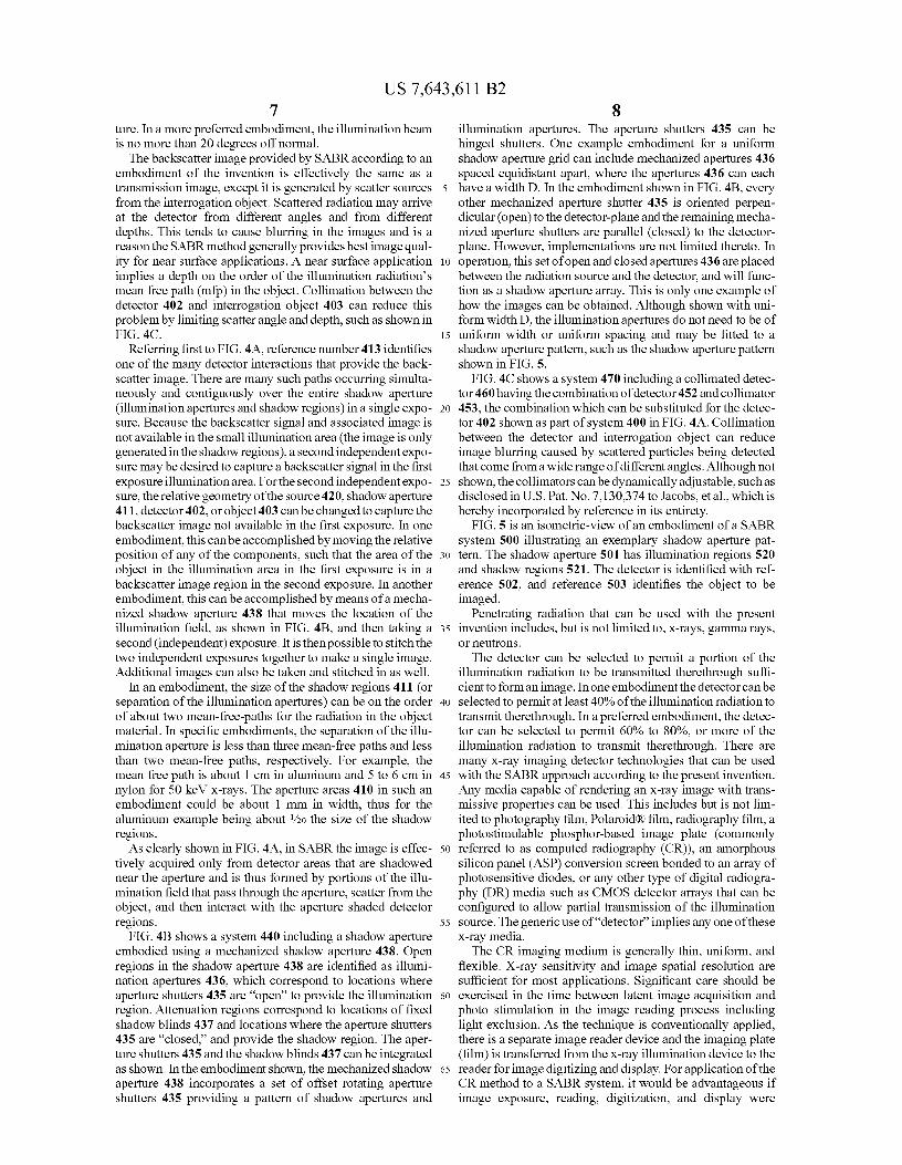
FIG. 4A shows a side-view of components of a Shadow5 Aperture Backscatter Radiography (SABR) system 400
according to an embodiment of the present invention. TheRadiography SABR system 400 includes a radiation source.The radiation source can bean x-ray tube 420, which providesa cone shaped illumination field. It should be noted that
10 SABR is not limited to a cone shaped illumination field.According to certain embodiments of the subject SABR sys-tem, any wide-area illumination pattern can be utilized.Referring again to FIG. 4A, the SABR system 400 caninclude a shadow aperture (mask) 401 having a plurality of
15 illumination regions 410 and shadow regions 411. Shadowregions 411 can be formed of radiation attenuating materials.The detector 402 of the SABR system 400 can be positionedin front of an object region 403 to be imaged. In one embodi-ment, the detector 402 can be a detector film.
20 The purpose of the shadow aperture 401 is to inhibit theillumination field from interacting with the detector 402 in thebackscatter image regions. The location of the shadow aper-ture 401 can remain general, but it is preferably located some-where between the source 420 and the detector 402. In an
25 embodiment not shown, the shadow aperture can be disposedon the detector. The backscatter image is obtained effectivelyonly in regions of the detector 402 associated with shadowedregions 411, such as region 414. One of the many illumination
30 paths associated with an example of backscattered radiationreaching region 414 is shown as reference 412, and the asso-ciated scatter interaction in the object region 403 is shown asreference 413. The detector 402 can be any detector mediumcapable of rendering a radiographic-like image or film-likex-ray image, including Polaroid® film, photography film,
35 radiography film or any digital and/or computed radiographysystem.
In a further embodiment, the detector 402 can be coupled toan optional computer or processor 435, which receives radia-
40 tion data from the detector 402 and performs data and imageprocessing, such as for generating a 3-D image from a plu-rality of images acquired at different radiation energies.
Typically, the illumination radiation field has an associatedarea with bounding lines of length on the order of several
45 inches, but depending on the source, shadow aperture, detec-tor, and object relative geometry, the field can easily beextended to several feet. The illumination field generated bythe radiation source 420 illuminates the entire area to beimaged. Because the illumination apertures 410 are small
50 with respect to the entire illumination field, the amount ofscatter radiation that is lost back-tracking (via scatter)through the aperture is generally very small with respect tothe scatter components forming the image.
As shown in FIG. 4A, the angle at which the illumination55 field passes through the aperture 410 increases with respect to
the direction normal to the detector 402. The angle relative tothe surface normal should preferably be limited. When theradiation from the radiation source spreads out in the coneshape shown, the cone shape generally limits angles for the
60 illumination beam for practical embodiments of the SABRapplication according to the invention to be similar to theamount of parallax that could be tolerated for transmissionradiography. Although the amount of the parallax-like effectthat can be tolerated is known to be generally interrogation
65 object dependent, in a preferred embodiment the illuminationbeam is no more than 25 degrees off normal with the othersystem components, such as the detector and shadow aper-
US 7,643,611 B27
8ture. In a more preferred embodiment, the illumination beam
illumination apertures. The aperture shutters 435 can be
is no more than 20 degrees off normal. hinged shutters. One example embodiment for a uniformThe backscatter image provided by SABR according to an shadow aperture grid can include mechanized apertures 436
embodiment of the invention is effectively the same as a spaced equidistant apart, where the apertures 436 can eachtransmission image, except it is generated by scatter sources 5 have a width D. In the embodiment shown in FIG. 413, everyfrom the interrogation object. Scattered radiation may arrive other mechanized aperture shutter 435 is oriented perpen-at the detector from different angles and from different
dicular (open) to the detector-plane and the remaining mecha-
depths. This tends to cause blurring in the images and is a nized aperture shutters are parallel (closed) to the detector-reason the SABR method generally provides best image qual- plane. However, implementations are not limited thereto. Inity for near surface applications. A near surface application io operation, this set of open and closed apertures 436 are placedimplies a depth on the order of the illumination radiation's
between the radiation source and the detector, and will func-
mean free path (mfp) in the object. Collimation between the tion as a shadow aperture array. This is only one example ofdetector 402 and interrogation object 403 can reduce this
how the images can be obtained. Although shown with uni-
problem by limiting scatter angle and depth, such as shown in
form width D, the illumination apertures do not need to be ofFIG. 4C. 15 uniform width or uniform spacing and may be fitted to a
Referring first to FIG. 4A, reference number 413 identifies shadow aperture pattern, such as the shadow aperture patternone of the many detector interactions that provide the back- shown in FIG. 5.scatter image. There are many such paths occurring simulta- FIG. 4C shows a system 470 including a collimated detec-neously and contiguously over the entire shadow aperture tor 460 having the combination of detector 452 and collimator(illumination apertures and shadow regions) in a single expo- 20 453, the combination which can be substituted for the detec-sure. Because the backscatter signal and associated image is tor 402 shown as part of system 400 in FIG. 4A. Collimationnot available in the small illumination area (the image is only
between the detector and interrogation object can reduce
generated in the shadow regions), a second independent expo- image blurring caused by scattered particles being detectedsure may be desired to capture a backscatter signal in the first
that come from a wide range of different angles. Although not
exposure illumination area. For the second independent expo- 25 shown, the collimators can be dynamically adjustable, such assure, the relative geometry of the source 420, shadow aperture
disclosed in U.S. Pat. No. 7,130,374 to Jacobs, et al., which is
411, detector 402, or object 403 can be changed to capture the
hereby incorporated by reference in its entirety.backscatter image not available in the first exposure. In one
FIG. 5 is an isometric-view of an embodiment of a SABR
embodiment, this can be accomplished by moving the relative system 500 illustrating an exemplary shadow aperture pat-position of any of the components, such that the area of the s y tern. The shadow aperture 501 has illumination regions 520object in the illumination area in the first exposure is in a and shadow regions 521. The detector is identified with ref-backscatter image region in the second exposure. In another erence 502, and reference 503 identifies the object to beembodiment, this can be accomplished by means of a mecha- imaged.nized shadow aperture 438 that moves the location of the
Penetrating radiation that can be used with the present
illumination field, as shown in FIG. 413, and then taking a 35 invention includes, but is not limited to, x-rays, gamma rays,second (independent) exposure. It is then possible to stitch the or neutrons.two independent exposures together to make a single image. The detector can be selected to permit a portion of theAdditional images can also be taken and stitched in as well. illumination radiation to be transmitted therethrough suffi-
In an embodiment, the size of the shadow regions 411 (or cient to form an image. In one embodiment the detector can beseparation of the illumination apertures) can be on the order 40 selected to permit at least 40% of the illumination radiation toof about two mean-free-paths for the radiation in the object
transmit therethrough. In a preferred embodiment, the detec-
material. In specific embodiments, the separation of the illu- tor can be selected to permit 60% to 80%, or more of themination aperture is less than three mean-free paths and less
illumination radiation to transmit therethrough. There are
than two mean-free paths, respectively. For example, the many x-ray imaging detector technologies that can be usedmean free path is about 1 cm in aluminum and 5 to 6 cm in 45 with the SABR approach according to the present invention.nylon for 50 keV x-rays. The aperture areas 410 in such an
Any media capable of rendering an x-ray image with trans-
embodiment could be about 1 mm in width, thus for the missive properties can be used. This includes but is not lim-aluminum example being about '/o the size of the shadow
ited to photography film, Polaroid® film, radiography film, a
regions. photostimulable phosphor-based image plate (commonlyAs clearly shown in FIG. 4A, in SABR the image is effec- 5o referred to as computed radiography (CR)), an amorphous
tively acquired only from detector areas that are shadowed
silicon panel (ASP) conversion screen bonded to an array ofnear the aperture and is thus formed by portions of the illu- photosensitive diodes, or any other type of digital radiogra-mination field that pass through the aperture, scatter from the phy (DR) media such as CMOS detector arrays that can beobject, and then interact with the aperture shaded detector configured to allow partial transmission of the illuminationregions. 55 source. The generic use of"detector" implies any one of these
FIG. 4B shows a system 440 including a shadow aperture x-ray media.embodied using a mechanized shadow aperture 438. Open
The CR imaging medium is generally thin, uniform, and
regions in the shadow aperture 438 are identified as illumi- flexible. X-ray sensitivity and image spatial resolution arenation apertures 436, which correspond to locations where sufficient for most applications. Significant care should beaperture shutters 435 are "open" to provide the illumination 60 exercised in the time between latent image acquisition andregion. Attenuation regions correspond to locations of fixed
photo stimulation in the image reading process including
shadow blinds 437 and locations where the aperture shutters
light exclusion. As the technique is conventionally applied,435 are "closed," and provide the shadow region. The aper- there is a separate image reader device and the imaging plateture shutters 435 and the shadow blinds 437 can be integrated
(film) is transferred from the x-ray illumination device to the
as shown. In the embodiment shown, the mechanized shadow 65 reader for image digitizing and display. For application of theaperture 438 incorporates a set of offset rotating aperture
CR method to a SABR system, it would be advantageous if
shutters 435 providing a pattern of shadow apertures and
image exposure, reading, digitization, and display were

US 7,643,611 B29
accomplished in the same device in order to eliminate thephysical transfer of the imaging plate in the process.
Most ASP detectors are neither thin nor homogeneous, butthere are panel models where the associated amplifiers andvoltage supplies are placed to the side of the imaging area. 5Typical panels are heavily shielded against x-ray penetrationfrom the rear, which tends to negate the geometric necessitiesof the SABR system. However, custom panels can be pro-duced to allow illumination passage.
A major advantage of anASP and CMOS detector arrays is 10
the inherent, single-step image acquisition process. Datafrom a sequence of images can be acquired and stored forprocessing. Image data obtained from a series of varyingx-ray generator voltages can be employed to yield 3D imagesof internal structure. Image data obtained from a series of 15x-ray generator pulses can also form the basis of analysis ofthe dynamic response of internal structure, such as suggestedin the development of dynamic radiography (Kenney &Jacobs, Research Techniques in Nondestructive Testing,Chapter 6, pp. 217-243, Edited by Sharpe, Academic Press, ^^1977). With sufficient temporal resolution of the panel, asingle x-ray generator pulse with time-varying spectrum canbe employed to efficiently acquire data for either of theseapplications.
25CCD or other chip-based detectors may also be used in
applications where a large area image is not required. Chipbased detectors are generally useful when the area to be
interrogated is relatively small, such as on the order of severalmicrometers, tens of micrometers, or hundreds of microme- 30ters, such as a region on an integrated circuit. Thin filmtransistor arrays (TFT-arrays) may also be used with embodi-ments of the invention.
Benefits from embodiments of the present invention areseveral and significant. The equivalent of an optical snapshot 35camera is often desirable, but has heretofore been generallyavailable only for conventional projection (transmission)radiography. Embodiments of the invention allow snapshotexposure radiography utilizing backscattered, rather thantransmitted, radiation. The compact size, absence of 40mechanical mechanisms, and small time increment for imageacquisition, contribute to efficiency, accuracy, and viability ofmany diagnostic and/or process-control applications. In con-trast to the related SBR approach, embodiments of the inven-tion allow such benefits using the full dynamic-range of the 45detector. This provides far greater image contrast and farlower image noise with much less, and even zero, image datamanipulation.
Embodiments of the present invention can be used in avariety of products. Obtaining images of internal structure, or 50defects, of objects is an important diagnostic tool in manyindustrial, military, security, and medical situations, particu-larly in cases in which there is only one-sided access to theobject and for which slow and expensive image acquisition isinappropriate. Other applications include situations wherein 55a near-surface (within approximately one radiation mean-free-path of the object surface) structure element, or defect, isdifficult or impossible to image by conventional projectionradiography. Moreover, all orders of scatter and transportthereby implied (i.e., radiography by selective detection(RSD) and lateral migration radiography (LMR)) utilized toproduce a backscatter image can be implemented throughembodiments of the subject SABR approach. RSD and LMRradiation path histories can enhance image contrast of sub-surface features that are obscured in other radiography tech-niques. Radiography applications, wherein internal struc-tures, or defects, are to be imaged, benefit significantly from
10the backscatter point of view of SABR. This approach makessuch examinations quick and inexpensive.
A clear benefit of the SABR approach is for radiographyapplications in which there is only one-sided access to theobject. For example, scanning electron microscopes (SEM)are commonly used in integrated circuit failure analysis andsome process control that require resolution beyond that pro-vided by standard optical inspections. One reason for com-mon use of SEMs in integrated circuit processing is becauseof its high image resolution compared to standard opticalinspection tools. Moreover, transmission radiography is gen-erally not possible for interrogating integrated circuits due tothe presence of one or more heavily absorptive surfaces. Forexample, gold may coat the backside of the chip. Signifi-cantly, unlike SABR systems that can interrogate below thesurface of a sample, conventional SEMs cannot interrogateregions below the surface. In addition, SABR systems areexpected to be inexpensive relative to SEMs. As noted above,the SABR system can provide improved image resolution,and provide a resolution comparable to that obtainable fromconventional SEMs by including one or more collimator sys-tems to reduce the beam size as required for the desiredresolution level.
Embodiments of the present invention are also helpfulwhere an internal structure element is difficult or impossibleto image by conventional transmission radiography or evenconventional backscatter radiography because of the abilityto take advantage of enhanced image contrast during thesubsurface scatter through the use of collimation. Accord-ingly, the present invention can be applied to Radiography byselective detection (RSD) described in U.S. Pat. No. 7,224,772 to Jacobs et al., which is hereby incorporated by referencein its entirety. RSD is an enhanced single-side x-ray Comptonbackscatter imaging (CBI) technique which selectivelydetects scatter components to improve image contrast andquality. Scatter component selection is accomplished througha set of specially designed detectors with fixed and movablecollimators. Adjustments to the adjustable collimator selectsparticular directions of travel of scattered radiation emittedfrom an irradiated object that reach the detector. The colli-mated detector is preferably a collimated detector array,where the collimators are independently adjustable. The inde-pendent motion capability provides the capability to focus theimage by selection of the desired scatter field components.When an array of reconfigurable collimated detectors is pro-vided, separate image data can be obtained from each of thedetectors and the respective images cross-correlated andcombined to form an enhanced image.
Embodiments of the invention can be applied to a variety ofapplications as they enable rapid large area, side-sided x-rayexposures that generates radiographic images of an object orvolume of interest and can also be incorporated into a portablesystem. For example, applications can include non-destruc-tive evaluation (NDE) of aluminum, carbon composites, andany low density material with favorable scattering-to-absorp-tion cross sections used in industrial applications.
Embodiments of the system can be small and lightweight,making the system readily mobile.
60 EXAMPLE
The present invention is further illustrated by the followingexample. This example is provided for illustration only and isnot to be construed as limiting the scope or content of the
65 invention in any way.FIG. 6 is a photograph of an exemplary shadow aperture
used for the present example. 631 are shadow regions made of

US 7,643,611 B211
lead sheeting. 632 are illumination regions which are theuncovered areas of a sheet of paper on which the lead shadowregion sheets are glued. FIG. 7 is a photograph of an objectarray used to test the SABR system. Reference 741 indicatespieces of lead. Reference 742 indicates various nuts andwashers made from aluminum, brass and steel. Reference 743indicates a nylon washer. The objects are provided on a sub-strate 744 made from 6/6 nylon. FIG. 8 is a single exposurex-ray SABR image of the object array shown in FIG. 7 usingthe shadow aperture shown in FIG. 6 obtained using a CRimage detector without any attempt of optimizing either theaperture or the x-ray exposure parameters. Thus, the SABRparameters, such as shadow aperture dimensions and x-rayillumination parameters, employed were chosen arbitrarilyand were likely not close to the optimums for the object used.The single x-ray exposure was 70 kVp for 120 mAs. The focalspot (FOC) of the x-ray tube was located 47 inches from thesurface of the film. FIG. 8 evidences the viability of thepresent invention. The result shown is meant to only exhibitsuch a demonstration. The object itself was chosen solely forease of demonstration rather than any practical interest.
It is to be understood that while the invention has beendescribed in conjunction with the preferred specific embodi-ments thereof, that the foregoing description as well as theexamples which follow are intended to illustrate and not limitthe scope of the invention. Other aspects, advantages andmodifications within the scope of the invention will be appar-ent to those skilled in the art to which the invention pertains.
Any reference in this specification to "one embodiment,""an embodiment," "example embodiment," etc., means that aparticular feature, structure, or characteristic described inconnection with the embodiment is included in at least oneembodiment of the invention. The appearances of suchphrases in various places in the specification are not neces-sarily all referring to the same embodiment. Further, when aparticular feature, structure, or characteristic is described inconnection with any embodiment, it is submitted that it iswithin the purview of one skilled in the art to effect suchfeature, structure, or characteristic in connection with otherones of the embodiments.
We claim:1. A radiography system, comprising:at least one penetrating radiation source for providing a
penetrating radiation field;at least one partially transmissive radiation detector,
wherein said partially transmissive radiation detector isinterposed between an object region to be interrogatedand the at least one penetrating radiation source, whereinthe at least one partially transmissive radiation detectortransmits a portion of the penetrating radiation fieldincident on the at least one partially transmissive radia-tion detector, and
a shadow aperture comprising a plurality of radiationattenuating regions having at least one illuminationaperture therebetween two or more of the plurality ofradiation attenuating regions, wherein the shadow aper-ture is disposed between the at least one penetratingradiation source and the at least one partially transmis-sive detector, wherein the at least one illumination aper-ture allows the penetrating radiation field to reach theobject region, wherein backscattered radiation from theobject region is detected by the at least one partiallytransmissive radiation detector in shadowed regions ofthe at least one partially transmissive radiation detectorthat are shadowed by the radiation attenuating regions ofthe shadow aperture.
122. The system according to claim 1, wherein the shadow
aperture comprises at least one shutter, wherein when one ofthe at least one shutter is open, the open shutter contributes tothe at least one illumination aperture, and wherein when one
5 of the at least one shutter is closed, the closed shutter contrib-utes to the plurality of radiation attenuating regions.
3. The system according to claim 2, wherein the shadowaperture is a mechanized shadow aperture, wherein the atleast one shutter is mechanized.
10 4. The system according to claim 1, wherein said shadowaperture is disposed on the at least one partially transmissiveradiation detector.
5. The system according to claim 1, wherein said shadowaperture is spaced apart from the at least one partially trans-
15 missive radiation detector.6. The system according to claim 1, wherein the at least one
partially transmissive radiation detector comprises a detectormedium capable of rendering a radiographic-like image.
7. The system according to claim 6, wherein the at least one20 partially transmissive radiation detector comprises a photo-
stimulable phosphorous-based image plate.8. The system according to claim 6, wherein the at least one
partially transmissive radiation detector comprises a TFT-based flat panel detector, an amorphous silicon panel, or a
25 CMOS array.9. The system according to claim 1, further comprising a
computer or processor for receiving radiation data from the atleast one partially transmissive radiation detector and forperforming data and image processing.
30 10. The system according to claim 1, further comprising atleast one collimator positioned between the at least one par-tially transmissive radiation detector and the object region.
11. The system according to claim 1, wherein the at leastone partially transmissive detector transmits at least 10% of
35 radiation incident on the at least one partially transmissivedetector.
12. The system according to claim 1, wherein the at leastone partially transmissive detector transmits at least 40% ofradiation incident on the at least one partially transmissive
4o detector.13. The system according to claim 1, wherein the at least
one illumination aperture are spaced apart from each other byless than three mean-free paths for the penetrating radiationfield in the object region.
45 14. A method for radiography, comprising:positioning a shadow aperture between an object region to
be interrogated and an at least one penetrating radiationsource, wherein the shadow aperture comprises a plural-ity of radiation attenuating regions having at least one
50 illumination aperture therebetween two or more of theplurality of radiation attenuating regions;
positioning at least one partially transmissive radiationdetector between the shadow aperture and the objectregion, wherein the at least one partially transmissive
55 radiation detector transmits a portion of the penetratingradiation field incident on the at least one partially trans-missive radiation detector;
directing a penetrating radiation field from the at least onepenetrating radiation source to the shadow aperture,
60 wherein the at least one illumination aperture allows thepenetrating radiation field to reach the obj ect region; and
detecting backscattered radiation from the object regionvia shadowed regions of the partially transmissive detec-tor shadowed by the radiation attenuating regions.
65 15. The method according to claim 14, further comprisingproducing an image from the detected backscattered radia-tion.

US 7,643,611 B213
16. The method according to claim 14, further comprisingdisplacing the shadow aperture relative to the object regionsuch that the portion of the object region to which the pen-etrating radiation field reached for the first image is shadowedby the plurality of radiation attenuating regions of the shadowaperture, directing a second penetrating radiation field,detecting additional backscattered radiation from the objectregion, and producing a second image, wherein the secondimage provides image data from the object region corre-sponding to where the penetrating radiation field reached theobject region for the first image.
17. The method according to claim 16, wherein the secondpenetrating radiation field has a different energy than thepenetrating radiation field.
18. The method according to claim 16, further comprisingcombining the first image and the second image into a com-bined image.
19. The method according to claim 14, wherein the firstimage is obtained exclusive of image processing.
20. The method according to claim 14, wherein the shadowaperture comprises at least one shutter, wherein when one ofthe at least one shutter is open, the open shutter contributes tothe at least one illumination aperture, and wherein when oneof the at least one shutter is closed, the closed shutter contrib-utes to the plurality of radiation attenuation regions.
21. The method according to claim 20, further comprisingmechanically closing one or more of the at least one shutterand/or mechanically opening other of the at least one shutter;
directing a second penetrating radiation field;detecting additional backscattered radiation from the
object region; andproducing a second image from the detected additional
backscattered radiation, wherein the second image pro-
14vides image data from the object region correspondingto where the penetrating radiation field reached theobject region for the first image.
22. The method according to claim 14, further comprising:5 directing at least one additional penetrating radiation field
to the shadow aperture, wherein each of the at least oneadditional penetrating radiation field has a differentenergy than each of the other at least one additionalpenetrating radiation field and the penetrating radiation
10 field;detecting a corresponding at least one additional backscat-
tered radiation from the object region; andproducing a corresponding at least one additional image
from the detected corresponding at least one additionalis backscattered radiation.
23. The method according to claim 14, wherein the at leastone partially transmissive detector transmits at least 10% ofradiation incident on the at least one partially transmissive
20 detector.
24. The method according to claim 14, wherein the at leastone partially transmissive detector transmits at least 40% ofradiation incident on the at least one partially transmissivedetector.
25 25. The method according to claim 14, further comprisingpositioning at least one collimator between the partially trans-missive detector and the object region.
26. The method according to claim 14, wherein the at leastone illumination aperture are space apart from each other by
30 less than three mean-free paths for the penetrating radiationfield in the object region.