United States Patent (lo) Patent US 7,966,866 B2 · (12) United States Patent Hansma et al. (54)...
36
16 mu uuuu ui iiui iiui mu uui iuu lull uui iuu iuui uu uii mi ( 12 ) United States Patent Hansma et al. (54) METHODS AND INSTRUMENTS FOR MATERIALS TESTING (75) Inventors: Paul Hansma, Goleta, CA (US); Barney Drake, Rena, NV (US); Douglas Rehm, Lompoc, CA (US); Jonathan Adams, Santa Barbara, CA (US); Jason Lulejian, Pismo Beach, CA (US) (73) Assignee: The Regents of the University of California, Oakland, CA (US) (*) Notice: Subject to any disclaimer, the term of this patent is extended or adjusted under 35 U.S.C. 154(b) by 591 days. (21) Appl. No.: 12/079,444 (22) Filed: Mar. 27, 2008 (65) Prior Publication Data US 2009/0056427 Al Mar. 5, 2009 Related U.S. Application Data (60) Provisional application No. 60/921,788, filed on Apr. 3, 2007. (51) Int. Cl. GOIN3138 (2006.01) GOIN31317 (2006.01) (52) U.S. Cl . ........................................................... 73/81 (58) Field of Classification Search ................ 73/81-85; 600/562 See application file for complete search history. (56) References Cited U.S. PATENT DOCUMENTS 1,770,045 A 3/1925 Shore et al. 2,803,130 A * 8/1957 Bernhardt ......................... 73/81 3,572,097 A * 3/1971 Kleesattel ....................... 73/573 (lo) Patent No.: US 7,966,866 B2 (45) Date of Patent: Jun. 28, 2011 3,956,925 A * 5/1976 Smith ............................... 73/81 4,304,123 A * 12/1981 Aschinger et al ................. 73/81 4,611,487 A * 9/1986 Krenn et al . ...................... 73/81 (Continued) OTHER PUBLICATIONS W.C. Oliver and G.M. Pharr. Measurement of hardness and elastic modulus by instrumented indentation: Advances in understanding and refinements to methodology. J. Mater. Res. 19 (2004), 3. (Continued) Primary Examiner John Fitzgerald (74) Attorney, Agent, or Firm Vista IP Law Group LLP (57) ABSTRACT Methods and instruments for characterizing a material, such as the properties of bone in a living human subject, using a test probe constructed for insertion into the material and a refer- ence probe aligned with the test probe in a housing. The housing is hand held or placed so that the reference probe contacts the surface of the material under pressure applied either by hand or by the weight of the housing. The test probe is inserted into the material to indent the material while main- taining the reference probe substantially under the hand pres- sure or weight of the housing allowing evaluation of a prop- erty of the material related to indentation of the material by the probe. Force can be generated by a voice coil in a magnet structure to the end of which the test probe is connected and supported in the magnet structure by a flexure, opposing flexures, a linear translation stage, or a linear bearing. Option- ally, a measurement unit containing the test probe and refer- ence probe is connected to a base unit with a wireless con- nection, allowing in the field material testing. 7 Claims, 27 Drawing Sheets https://ntrs.nasa.gov/search.jsp?R=20110013021 2018-11-14T15:27:55+00:00Z
Transcript of United States Patent (lo) Patent US 7,966,866 B2 · (12) United States Patent Hansma et al. (54)...

16
mu uuuu ui iiui iiui mu uui iuu lull uui iuu iuui uu uii mi
(12) United States PatentHansma et al.
(54) METHODS AND INSTRUMENTS FORMATERIALS TESTING
(75) Inventors: Paul Hansma, Goleta, CA (US); BarneyDrake, Rena, NV (US); Douglas Rehm,Lompoc, CA (US); Jonathan Adams,Santa Barbara, CA (US); JasonLulejian, Pismo Beach, CA (US)
(73) Assignee: The Regents of the University ofCalifornia, Oakland, CA (US)
(*) Notice: Subject to any disclaimer, the term of thispatent is extended or adjusted under 35U.S.C. 154(b) by 591 days.
(21) Appl. No.: 12/079,444
(22) Filed: Mar. 27, 2008
(65) Prior Publication Data
US 2009/0056427 Al Mar. 5, 2009
Related U.S. Application Data
(60) Provisional application No. 60/921,788, filed on Apr.3, 2007.
(51) Int. Cl.GOIN3138 (2006.01)GOIN31317 (2006.01)
(52) U.S. Cl . ........................................................... 73/81(58) Field of Classification Search ................ 73/81-85;
600/562See application file for complete search history.
(56) References Cited
U.S. PATENT DOCUMENTS
1,770,045 A 3/1925 Shore et al.
2,803,130 A * 8/1957 Bernhardt ......................... 73/81
3,572,097 A * 3/1971 Kleesattel ....................... 73/573
(lo) Patent No.: US 7,966,866 B2(45) Date of Patent: Jun. 28, 2011
3,956,925 A * 5/1976 Smith ............................... 73/814,304,123 A * 12/1981 Aschinger et al ................. 73/814,611,487 A * 9/1986 Krenn et al . ...................... 73/81
(Continued)
OTHER PUBLICATIONS
W.C. Oliver and G.M. Pharr. Measurement of hardness and elasticmodulus by instrumented indentation: Advances in understandingand refinements to methodology. J. Mater. Res. 19 (2004), 3.
(Continued)
Primary Examiner John Fitzgerald(74) Attorney, Agent, or Firm Vista IP Law Group LLP
(57) ABSTRACT
Methods and instruments for characterizing a material, suchas the properties of bone in a living human subject, using a testprobe constructed for insertion into the material and a refer-ence probe aligned with the test probe in a housing. Thehousing is hand held or placed so that the reference probecontacts the surface of the material under pressure appliedeither by hand or by the weight of the housing. The test probeis inserted into the material to indent the material while main-taining the reference probe substantially under the hand pres-sure or weight of the housing allowing evaluation of a prop-erty of the material related to indentation of the material bythe probe. Force can be generated by a voice coil in a magnetstructure to the end of which the test probe is connected andsupported in the magnet structure by a flexure, opposingflexures, a linear translation stage, or a linear bearing. Option-ally, a measurement unit containing the test probe and refer-ence probe is connected to a base unit with a wireless con-nection, allowing in the field material testing.
7 Claims, 27 Drawing Sheets
https://ntrs.nasa.gov/search.jsp?R=20110013021 2018-11-14T15:27:55+00:00Z

US 7,966,866 B2Page 2
U.S. PATENT DOCUMENTS 5,463,897 A 11/1995 Prater5,473,700 A 12/1995 Fenner, Jr.
6,068,604 A 5/2000 Krause et al. 5,904,658 A 5/1999 Niederauer et al.6,142,010 A 11/2000 Merck, Jr. OTHER PUBLICATIONS6,247,356 B1 6/2001 Merck, Jr. et al.6,405,599 B1 6/2002 Part C. A. J. Putman, H. G. Hansma, H. E. Gaub, and P. K. Hansma,6,520,004 BI* 2/2003 Lin ................................... 73/81 Langmuir 8, 3014 (1992).6,983,643 B2 * 1/2006 Brighton et al . .................. 73/81 Briscoe, B.J. and Sebastian, K.S. An analysis of the durometer inden-7,878,987 B2 * 2/2011 Hansma et al . ............... 600/587 tation. Rubber Chemistry and Technology 66 (5): 827-836 1993).
2002/0170360 Al 11/2002 Anand et al. James B. Thompson et al., Nature 414, 774, Dec. 13, 2001.2005/0016264 Al * 1/2005 Anthe et al . ...................... 73/82 Paul K. Hansma, Patricia J. Turner, and Georg E. Fantner, Bone2005/0113691 Al 5/2005 Liebschner Diagnostic Instrument, Review of Scientific Instruments 77, 0751052005/0262685 Al 12/2005 Takaoka et al. (2006).
2006/0130566 Al* 6/2006 Wu ................................... 73/82 Micro Hardness Tester (MITT) for fracture toughness determination
2006/0184251 Al 8/2006 Zhang et al. of brittle materials, No. 8, Jul. 1998.
2007/0276292 Al* 11/2007 Hansma et al. 600/587 CSM Indentation Testers, four page brochure, Jan. 2009.ASTM Proposed Instrumented Indentation Testing Standard, pp. 1-4,
5,305,633 A * 4/1994 Weissenbacheretal. ........ 73/82 Oct. 2003.5,373,730 A * 12/1994 Kovacevic ........................ 73/815,450,745 A 9/1995 Flaherty * cited by examiner

1
ii
22104
1
It
10
106
22104
8
U.S. Patent ,Tun. 28, 2011 Sheet 1 of 27 US 7,966,866 B2
106
FIG. 1A
FIG. I BPRIOR ART
FIG. 1 C
FIG. 1 DPRIOR ART

FIG. 291,41PRIOR ART
206
U.S. Patent ,Tun. 28, 2011 Sheet 2 of 27 US 7,966,866 B2
204
208
204-'---d
FIG. 2B

U.S. Patent Jun. 28, 2011 Sheet 3 of 27 US 7,966,866 B2
16
FIG. 3

U.S. Patent Jun. 28, 2011 Sheet 4 of 27 US 7,966,866 B2
F16
FIG. 4

51
500
518
FIG. 5A
U.S. Patent ,Tun. 28, 2011 Sheet 5 of 27 US 7,966,866 B2
Fiil^'
U.S. Patent ,Tun. 28, 2011 Sheet 6 of 27 US 7,966,866 B2

U.S. Patent ,Tun. 28, 2011 Sheet 7 of 27 US 7,966,866 B2
FIG. 6A
602
6C
604
606
606 602
604
6C
L -
FIG. 6B FIG. 6C

OO
O
E
NOO ^
0000OOO
U.S. Patent Jun. 28, 2011 Sheet 8 of 27
US 7,966,866 B2
ZO
Qo'^ m C0 ^ N m r- U") NW E m 00 1^ CO ^ r^) Np N O O O O O O O OJ O O O O O O O O O
'-O
oX o y^_y;:^ . _:; O
`J

8C
L -8C
- A
U.S. Patent ,Tun. 28, 2011 Sheet 9 of 27 US 7,966,866 B2
FIG. SA
FIG. 8B FIG. 8C

9029009('"
U.S. Patent ,Tun. 28, 2011 Sheet 10 of 27 US 7,966,866 B2
FIG. 9A FIG. 9B FIG. 9C
910
908 0
908 912 910 914
FIG. 9D FIG. 9E

OOA
0
V
OOA
lqd-0
0
NOA
0
NAO O_A OA
OA(O
V-
O
NOA
OO ^,OO
C'4
A
OOA0
aoAOA0
OOOA^OAOA
U.S. Patent Jun. 28, 2011
Sheet 11 of 27 US 7,966,866 B2

U.S. Patent Jun. 28, 2011
Sheet 12 of 27 US 7,966,866 B2
N ^
N NwAw
I"'
'^ NA wA ww
`V [wA AA Aw A
OAA
rAVe}'w^A
w
I:t wO A A^. Aww
0^, wO ^^ww
O Ow wA AA
CoOAA
AA
Nw AN `^wA
U.S. Patent Sheet 13 of 27Jun. 28, 2011 US 7,966,866 B2
1204
1212
1214
1226 1222
'161:
12.34
2.38
1242
4
1248
FIG. 12

U.S. Patent Jun. 28, 2011 Sheet 14 of 27 US 7,966,866 B2
;, a 1312
FIG. 13
U.S. Patent ,Tun. 28, 2011 Sheet 15 of 27 US 7,966,866 B2
T
FIG. 14A

U.S. Patent ,Tun. 28, 2011 Sheet 16 of 27 US 7,966,866 B2
FIG. 14B

U.S. Patent ,Tun. 28, 2011 Sheet 17 of 27 US 7,966,866 B2
FIG. 15
1506
530
1508
72
U.S. Patent ,Tun. 28, 2011 Sheet 18 of 27 US 7,966,866 B2
5
4
3
Z
' A-' 2UO
1
0
-10 10
FIG. 1 6A
20 30 40 50TIME (S)
A
10 20 30 40 50TIME (S)
100
E
wUZQ(/70 0
-1004
FIG. 16B 0

U.S. Patent ,Tun. 28, 2011 Sheet 19 of 27 US 7,966,866 B2
00N
OIn
E
O WO C-)
ZQLnD
O
r- cD Ln r7
(N) 33d0J
ON O
^J

765
z 4
w 3U0 2
0
—1
C)^O 2L^
W 3 W 3UO 2U-
21 4
7
5
z 4
7
5
RETRACTION
SLOPE
FIRST CYCLELAST CYCLE
oW^CL
Z^^
0 50 100 150 200
DISTANCE (/.lm)
FIG. 17C
10 20 30 40 50
TIME (S)
FIG. 17E
0
.1
5
4
z 3
w 2UOf
0 1L_
0 110
U.S. Patent Jun. 28, 2011
Sheet 20 of 27 US 7,966,866 B2
765
z 4
w 3U0 2
10
-10
/ MAXIMUM
INDENTATION
DISTANCE
50 100 150 200
DISTANCE (Am)
FIG. 1 7A
JM
FORCEAFTER PAUSE
0 50 100 150 200
DISTANCE (elm)
FIG. 17B
0
10 50 100 150 200
DISTANCE (ILm)
FIG. 170STRIPED AREA=
7--WORK OF INDENTATION
6- ENERGY DISSIPATED
5 IN INDENT-REPEATELASTIC
CYCLE
z 4 RECOVER)
W 3U0 2
1
0—1
0 50 100 150 200
DISTANCE (/.Lm)
FIG. 17F

7
6
5
4zU 3O
L.^
2
1
0
—1
0 50 100 150 200
Distance [UM]
U.S. Patent ,Tun. 28, 2011 Sheet 21 of 27 US 7,966,866 B2
Contact Area ARetraction Slope SMaximum Force After Pause mox
Maximum Indentation Distance hContact Indentation Distance heHardness HElastic Modulus EPoisson Ratio vIndenter cone half—angle 0
'e=h-0.72 P S x
A=7ncC2 ton(0) 1 +tan(0)
H= PmaxA
1 — vsample2Esample —
2 -^A 1 — vindenter2
`/TS Endenter
FIG. 18PRIOR ART

OO
u7 O N O
N N ^C ^c Y O UO U C CU p
to m O'y ^ dC
U O 1.^
a^a oo ^v ^
E o 3^ oz y ^
E
wm =
'p dp N
C^m1
O
p
00z
uuujE 27 ^
C O y C71C^ O C OO ^ OG G tG U E
d Q
cL2Cl-pNO
DODDN ` y N2 U
N T ^OU ^
=° p OW 7a
^ UZ Cn
Ocxar0+N
COU
U
X
VE
OCO
a
O
O
O
.O VO
Cn l^
U.S. Patent ,Tun. 28, 2011 Sheet 22 of 27 US 7,966,866 B2
N
0
1 >
UN
N C
I I+J N 1 CO l!7 1 1""J N O C=)0.- `- O O O O O O O O
(n) 33dOJ
NO OO O
M OOf O
C6
O
CRV' N O 00 (D ^' N O N O C O O O O O O O O0 0 0 0 0 0 0 N N O ' N M 'i O

U.S. Patent Jun. 28, 2011 Sheet 23 of 27 US 7,966,866 B2
0
°co0
u ^p o Oo N ^\ od c OcoL2, -;5 NnNw
OLA
'N ^ M
7
.0 rCr O O
^ Ip ov
O.
Q ^ O ^2 mrn
-C, c oo
L2 ^ O
:^x 'd'p c0^
0O
O_y CO
Ouy I
p p Nc C
E! coM
° Io ^c Oa
CID Ir-N
N OvO^ fn O c0 LO U13 d' M l!") N
l! )^[") ll•) O ^f")
= 0 O d M N C=; O
c (N) 93JOJ
.Ei
v N M Mo ^,c
^, o v'o Mo v
w c N LA0 O N
c 5O
N O=E V N
U C:)N r
OW N
W N N L!) N^^ N
C L^ ^~^ E
C ON d Ovd t
Q^ O
NN N LOO OT O Mp GAO N LA
O
° w
OLW Q O O O O O O O O
r- CO M C',4 '- O•°
O OO N rn - l^-1\ U I I 1 1 O
C-1z
(SUOJ^lw) aDuo}sip ^ (N) a^JO^L^ 3 N d
OD
ON
r ^.V

U.S. Patent Jun. 28, 2011 Sheet 24 of 27 US 7,966,866 B2
Uu 0 cc 0O y
C
•O Nnp C NN
PYa C O)
d wo nd OQ ^ N
^ coO)Lao u')n
^ x ^: v^\0L^ Oy N O
M NC N C
COy C
o Of'c•-^ tGN (rDayi OC Q)VO2
0
0cL^
V NO CZEV ^ ^O OS
W ^ ^O NC ^y v0
00 VO(U C>N 1^ WO N NW UO ^OC °CN wv tN
N y ^.^ O OT D.O •yQ
y t0 NO ^ - C'-^O TO 0
cc wOU \ N °V O)O O
:U 3v °0D
0Od
M
N E
dO Oa
C=) cz^ C:3 CD C= CD CD C^l C^ C^ C^ C^ C=) C=) cm C=>•!Ny O Q) QO I^ c0 lf") ^ M N O O) OO I^ CO t!]
dw
apn}ildwy
t^
N•
U.S. Patent ,Tun. 28, 2011 Sheet 25 of 27 US 7,966,866 B2
vo CO
^8
^y odOO
CO>^ O N
Or
y N-N ^ MC D7^4 r ~d W^ OQ ^
O^ coO OL^
M
c x d':C o (G
0
Hw GNOO
CNC Mv O O`oZ UO (O
N Oo'c
^
r^o= O
0
N E
'C
C
^O ^
y^
M v"v. Oo =WO_
Vy
CH
^O
O UV O- M OWN 1^W N NVCL LLvCN
O•NNyN LZ!
TONN t!)O T y
OQ
0y t0 N_
O W °v
co co co co ca cn r r r r r r r r r o°C\ Wj dv co
LF7co m m m m m m m md: r? N — O1 00 r co m m m m m
Lc) -4- M NO
O
o ^ o y apnl!IdwyV ^ 3 tO ^°
NN
Iu^_

U.S. Patent ,Tun. 28, 2011 Sheet 26 of 27 US 7,966,866 B2
a ao
o0U C dO ° d
O N\ CVC
•O Nd N
'N v Md C O)
d 4JO OQ ^ d M MV ^
O^ Y ^
0i^N °Nc LO
O o coo ^
° c0V o
v ^
nN ^m ov C.4 N W
Ex° o
0
E
:n'c
c°
N^ NO C^ O vM OO O =W ^o °
NC SJ
^ O
CD V0U OM GN 1^ L'iO N NW Vo L2c c'° ON
NLd
Ny 1/1 ^ y0T C O'NNQ
C CEO^ CnWOo O O
M LO C) LO 00 Ln r-', V' M cV N OD r, [D InO O O O rn O^ °^ O^ O^c5
d5C \ W NOR N N N N N N O N N N N 0 0 0 0 O O O O O
o `—' apn}gdwy epn^!!dwyo \ ^,
o W =D
J
N
`J

110
2402
2422
U.S. Patent ,Tun. 28, 2011 Sheet 27 of 27 US 7,966,866 B2
FIG. 24

US 7,966,866 B21
METHODS AND INSTRUMENTS FORMATERIALS TESTING
CROSS-REFERENCE TO RELATEDAPPLICATIONS
This application claims the benefit of Provisional PatentApplication No. 60/921,788, filed Apr. 3, 2007, which isincorporated herein in its entirety.
10
STATEMENT REGARDING FEDERALLYSPONSORED RESEARCH OR DEVELOPMENT
This invention was made with Government support underGrant no. ROI GM 065354-05 from the National Institutes of 15
Health and Grant no. NCC-1-02037 from NASA. The Gov-ernment has certain rights in this invention.
FIELD OF THE INVENTION20
The invention relates to an apparatus and method for mate-rials testing.
BACKGROUND OF THE INVENTION25
Indentation testing to determine the hardness of materialshas a long history. Conventional indentation tests include theBrinell hardness test, the Rockwell hardness test, and theVickers hardness test. The Brinell and Vickers tests involveindenting at a fixed load and then examining the diameter of 30
the indentation. As shown schematically in FIG. 1A, theRockwell test, which is the most commonly used test,involves measuring the depth of indentation from a fixed loadby measuring how far a test probe 102 goes into the materialunder test 104. This requires a rigid frame 106. It cannot work 35
if there is a soft layer in the mechanical path from the top ofthe material under test 104 down through the rigid frame 106and back to the test probe 102 that will deform during inden-tation (as indicated schematically by the springs 108 in FIG.1C) because the distance that the test probe 102 goes into the 40
material under test 104 cannot be distinguished from thedeflection of the soft layer. A real example of this problemwould be attempting to measure the Rockwell hardness of abone surface exposed during surgery. The soft tissue betweenthe bone and the table on which the body rested would be like 45
the springs 108 shown in FIG. 1C.The development of very sensitive methods for measuring
the depth of indentations such as capacitance sensors, opticalbeam deflection, laser interferometers or even very sensitivelinear variable differential transducers, LVDTs, together with 50
the development of sophisticated techniques for determiningmechanical parameters from force vs. distance data only, (ref.W. C. Oliver and G. M. Pharr. Measurement of hardness andelastic modulus by instrumented indentation: Advances inunderstanding and refinements to methodology. J. Mater. 55
Res. 19 (2004), 3. (review article)), has made possible a newclass of indentation machines called nanoindentation testersor nanoindenters. They typically use submicrometer indenta-tions. Nanoindentation testors also use a rigid frame 106 asshown schematically in FIG. lA to enable accurate measure- 60
ment of the distance that an indenter goes into the sample at afixed load for macroindentation tests or variable loads fornanoindentation tests. Again, a substantial soft layer underthe sample as shown in FIG. 1C would prevent accuratenanoindentation testing. 65
This solution to the problem of soft layers has been previ-ously implemented, for example, in U.S. Pat. No. 1,770,045,
2with a durometer as shown in FIG. 2A. In this case a rigidframe is not needed because the base of the durometer 202rests directly on the material under test 204 and indentationsof the test probe 206 (sometimes called the foot) into thematerial are measured relative to the position of the base ofthe durometer 202. However, durometer indentation mea-surements only characterize the material with a hardnessnumber. Attempts have been made to relate hardness mea-surements taken with a durometer to the elastic modulus ofthe material. However, no accurate, widely accepted model isavailable. This is in part due to the difficulties in theoreticalanalysis arising from the complex indenter geometry, and theinability to correct for time-dependent effects because of alack of control of the loading rate with the durometer[Briscoe, B. J. and Sebastian, K. S. An analysis of the durom-eter indentation. Rubber Chemistry and Technology 66 (5):827-836 1993)].
Other prior art portable hardness testers also exist. In par-ticular there are many rebound testers such as the TH130 andTH150 pocket-size hardness tester from Corvib and manyultrasonic hardness testers such as the High ResolutionSH-21 Portable Hardness Tester from Micro Photonics Inc.Here too, however, to the best of our knowledge there existsno portable tester that measures more material propertiesbeyond just hardness.
One approach to indentation measurement on soft samplesis to use, as a distance reference, the upper surface of thesample as is found in the instrument outlined in U.S. Pat. No.6,142,010. In spite of this improvement, this instrument islimited in that it is solely designed for measuring hardnessand relies on an external mechanical frame (as opposed to areference probe) to maintain a rigid mechanical path betweenthe sample and the distance measurement. The upper surfaceof the sample is used for a differential measurement of theindentation depth in the CSM Indentation Testers, which canmeasure more that just hardness. Here again, however, a rigidframe is present.
Atomic Force Microscopes (AFMs) can rest on the surfaceof the material under test and could, in principle at least, beused for indentation tests [C. A. J. Putman, H. G. Hansma, H.E. Gaub, and P. K. Hansma, Langmuir 8, 3014 (1992)]. Anexample of indentation tests on bone with the AFM is JamesB. Thompson et al., Nature 414, 774, 13 Dec. 2001, thoughthis was done with a prototype AFM that was not capable ofresting on the surface of the material under test.
One AFM company, Asylum Research, has also produceda nanoindenter, the MFP-3D NanoIndenterTM for Quantita-tive Surface Characterization. This instrument eliminates theproblem of angular motions of cantilevers and goes to higherforces, up to 14 milliNewtons. It consists of a new NPSTMNanopositioning sensor for their MFP-3D TM Stand AloneAtomic Force Microscope. The sample is held rigidly to theMFP-3D scanner through specialized sample mounts. Thus itis not designed to rest on the surface of the sample as for thepresent invention.
Other publications dealing with prior art systems include:U.S. Pat. No. 5,450,745; U.S. Patent Publication Nos. 2002/0170360 and 2005/0262685; "Micro Hardness Tester (MHT)for fracture toughness determination of brittle materials", No.8, July 1998; CSM Indentation Testers, four page brochure;and "ASTM Proposed Instrumented Indentation TestingStandard", pages 1-4, October 2003.
Thus, while there have been portable hardness testingdevices and devices that measure parameters other than hard-ness, we are aware of no prior device that combine the abilityto be portable with the ability to measure a wide variety ofparameters based on indentation of a probe into a sample.
US 7,966,866 B23
BRIEF SUMMARY OF THE INVENTION
The present invention overcomes the foregoing drawbacksin providing improvements in the technology for measuringmaterial properties of materials such as bone in a living per-son, teeth, the leg bones of race horses, the wing of an aircraft,the surface of a part during manufacturing or assembly andother structures that are not easily tested in conventionalmechanical testers.
The invention is designed to measure more parameters thanjust hardness. This is important for many applications such aspredicting bone fracture resistance or monitoring fatiguedamage in airplane wings where measurements of hardnessalone are not sufficient. Thus, compared with the devicesreferred to above in the BACKGROUND OF THE INVEN-TION section, the invention extends the capabilities of pre-vious instruments for measuring the material properties ofmaterials under test by making it possible to measure morematerial properties than just hardness with a portable instru-ment. Moreover, the instrument can be portable and handheld. At the heart of the invention is a measurement head thatcontains a reference probe that rests substantially on the sur-face of the material under test and provides a reference formeasuring the distance that a test probe indents the materialunder test. The invention can, optionally, measure completeforce vs. distance curves during one or multiple indentationcycles where the force is the force that the invented instru-ment supplies during the indentation cycle(s).
More particularly, in a departure from prior devices, weprovide a device and method for characterizing a materialusing a test probe and constructed for insertion into the mate-rial and a reference probe aligned with the test probe in ahousing. The housing is hand held or placed so that thereference probe contacts the surface of the material underpressure, applied either by hand or by the weight of thehousing, causing the test probe to indent the material whilemaintaining the reference probe substantially under saidpres-sure. This allows the evaluation of one or more properties ofthe material related to indentation of the material by theprobe.
Referring again to FIGS. 1A-1D, the invention replaces therigid frame 106 with a reference probe 110 that rests directlyon the surface of the sample. Now, as will be further detailedbelow, the relevant mechanical path will be from the materialup through the reference probe 110 and back down to the testprobe 102.
The invention increases the capability of the durometer byadding a measurement head containing electronic actuators togenerate forces and/or displacements as well as sensors forload and displacement that are coupled to a computerizeddata generation, collection and analysis system to get manyparameters beyond just hardness. Compared with otherinstrumented indentation systems capable of measuringproperties beyond hardness, our invention greatly increasesthe ability to test samples with complex geometries or inlocations where attachment of a sample to a rigid sampleholder is impossible.
The invention is also distinct from the above describedAFMs in that the test probes of the invention are not mountedon cantilevers as for the AFMs. Thus there is not the problemof angular motions of cantilevers. Also, the preferred embodi-ments of the present invention typically go to much largerforces, several Newtons, compared to the microNewtons,nanoNewtons or below as typical ofAFMs. This is an advan-tage for testing real materials without special surface prepa-ration because the probed volume is large enough to be insen-
4sitive to thin surface layers of, for example, the water thatcovers most materials in ambient environments, and surfacetopography.
An additional feature of the invention is an optional wire-s less connection between a portable measurement head, which
contains the mechanical components necessary for the mea-surements together with some electronics, and a base station,which contains electronics including, optionally, a computer.The base station can both supply instructions for the measure-
10 ments and acquire data from the measurements.Another additional feature of the invention is the optional
ability to hand-hold the measurement head. This increases theease and speed with which measurements can be made on
15 complex structures such as airplane landing gear or a racehorse's leg. The combination of wireless operation and a handheld measurement head is particularly useful for measure-ments in the field: outside a testing lab.
Still another feature enabling a compact hand-holdable20 instrument with the extensive capabilities of the invention is
the use of opposing flexures with a linear translation stage thatfacilitate incorporation of a voice coil actuator.
BRIEF DESCRIPTION OF THE DRAWINGS25
For a more complete understanding of the present inven-tion, reference is now made to the following descriptionstaken in conjunction with the accompanying drawing, inwhich:
30 FIGS. 1A-1D are schematic drawings illustrating theadvances in the present invention over the prior art instru-ments that rely on a rigid frame for measuring the depth ofindentation;
FIGS. 2A and 2B are schematic drawings illustrating the35 advances in the present invention over the prior art instru-
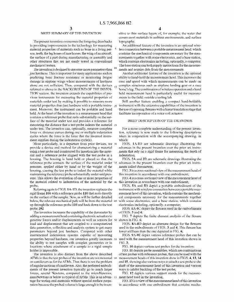
ments called durometers;FIG. 3 is a cross-sectional view of the measurement head of
this invention in accordance with one embodiment;FIG. 4 is a cross-sectional view of the measurement head of
40 this invention in accordance with one embodiment;FIGS. 5A and 5B depict a portable embodiment of the
instrument with wireless connection between a portable mea-surement head of this invention, which contains the mechani-cal components necessary for the measurements together
45 with some electronics, and a base station, which containselectronics including, optionally, a computer;
FIGS. 6A-6C depict the flexures used in the embodimentsof FIGS. 3 and 4;
FIG. 7 depicts the finite element analysis of the flexure50 shown in FIG. 6;
FIGS. 8A-8D depict an alternate design for the flexuresused in the embodiments of FIGS. 3 and 4. This flexure haslower stiffness than the one depicted in FIG. 6;
FIGS. 9A-9E depict various reference probes that can be55 used with the measurement head of this invention shown in
FIG. 3;FIG. 10 depicts various test probes for the invention;FIG. 11 depicts probe assemblies, which are combinations
of test probes with reference probes, that can be used with the60 measurement heads of this invention show in FIGS. 4, 13, 14
and 15, showing also various ways to attach a test probe to theshaft of the measurement head of this invention and variousways to inhibit buckling of the test probe;
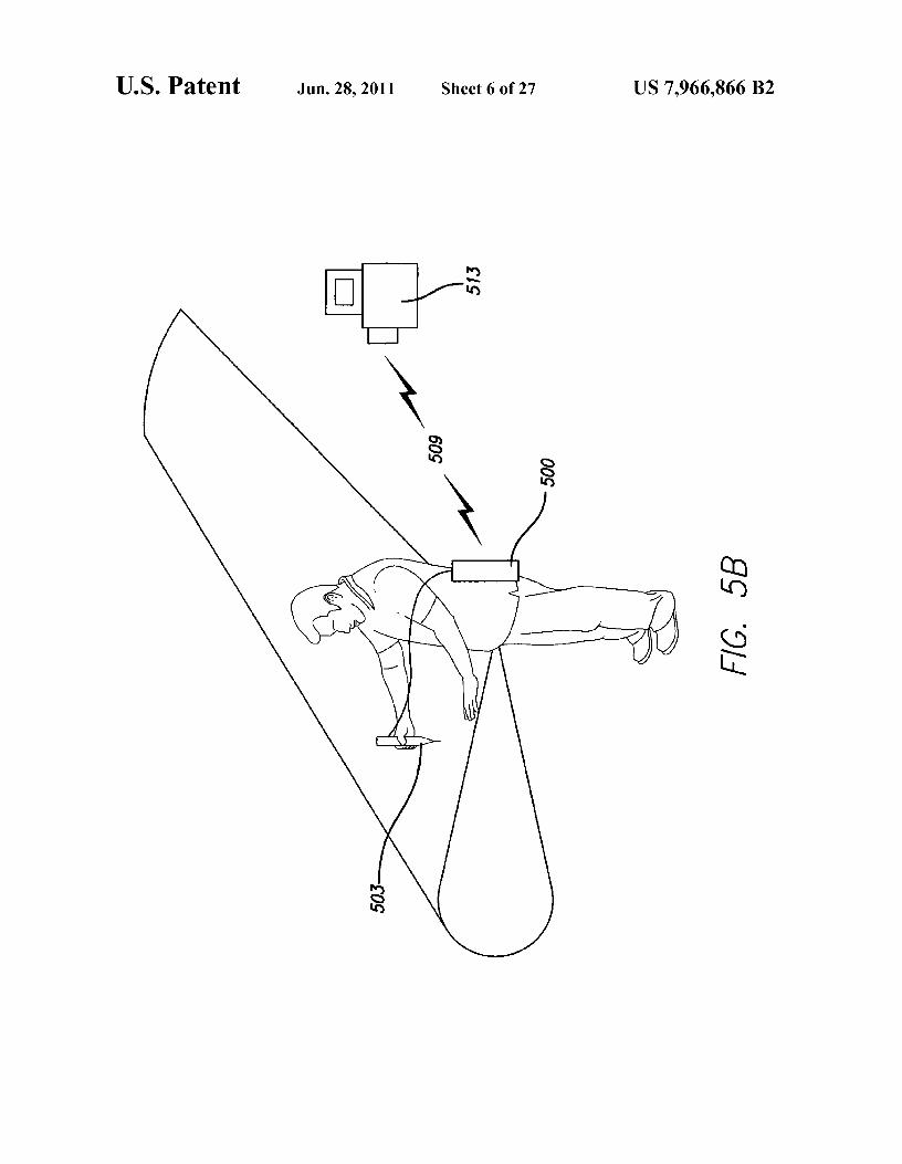
FIG. 12 depicts various support stands for the measure-65 ment head used in the invention;
FIG. 13 is a view of the measurement head of this inventionin accordance with one embodiment that contains mecha-

US 7,966,866 B25
nisms for both a coarse and fine adjustment of the relativeposition of a test probe and a reference probe;
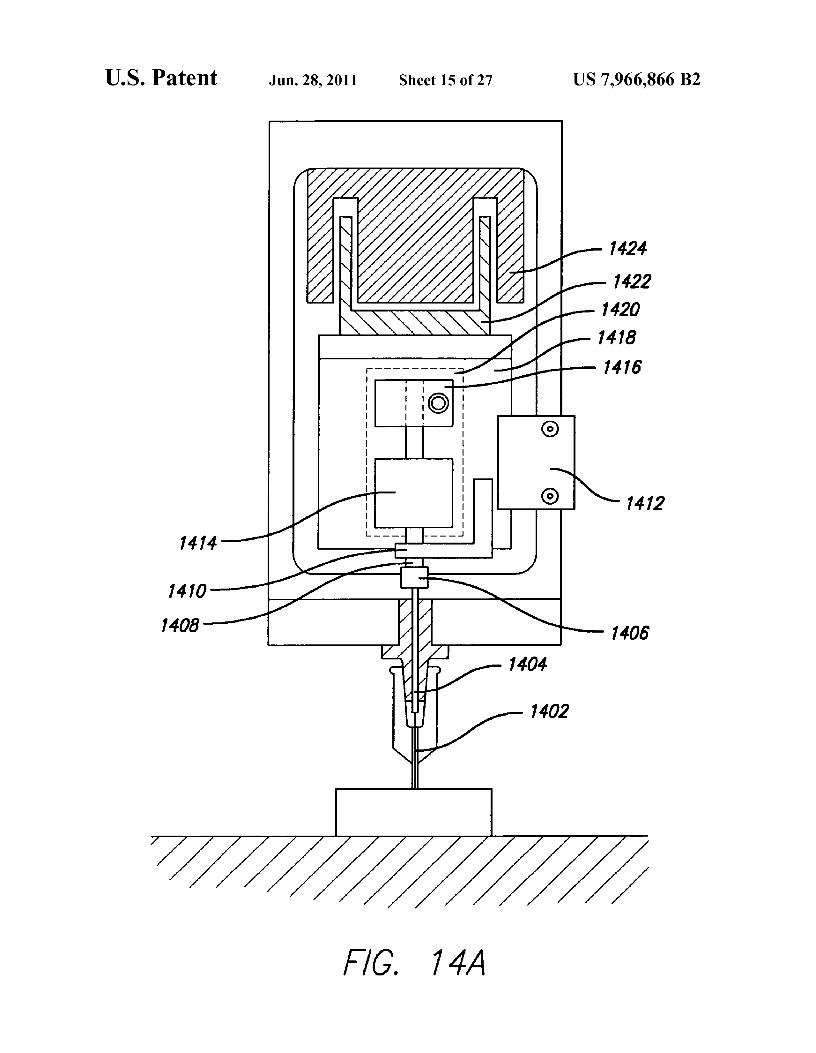
FIGS. 14A and 14B are views of the measurement head ofthis invention in accordance with two embodiments that use alinear stage rather than flexures;
FIG. 15 is a view of the measurement head of this inventionin accordance with one embodiment that uses wire flexuresrather than the disk flexures of FIGS. 3 and 4 or the plasticflexures of Clark Synthesis force generator shown in FIG. 13;
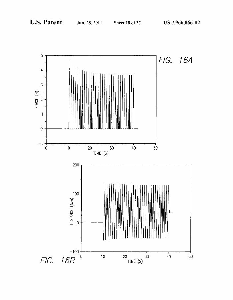
FIGS. 16A-16C show three types of data graphs that can begenerated with this invention;
FIGS. 17A-17F show various parameters that can beextracted from data graphs generated with this invention;
FIG. 18 shows prior art equations [W. C. Oliver and G. M.Pharr. Measurement of hardness and elastic modulus byinstrumented indentation: Advances in understanding andrefinements to methodology. J. Mater. Res. 19 (2004), 3.] forcalculating Hardness and Elastic Modulus;
FIG. 19 shows a screenshot of the user interface of theLabview program used in the currently preferred embodimentto control the invention;
FIG. 20 shows a screenshot of the automated data analysisinterface of the Labview program used in the currently pre-ferred embodiment;
FIG. 21 shows a screenshot of the automated data analysiscurve of Energy Dissipated as a function of time from theLabview program used in the currently preferred embodi-ment;
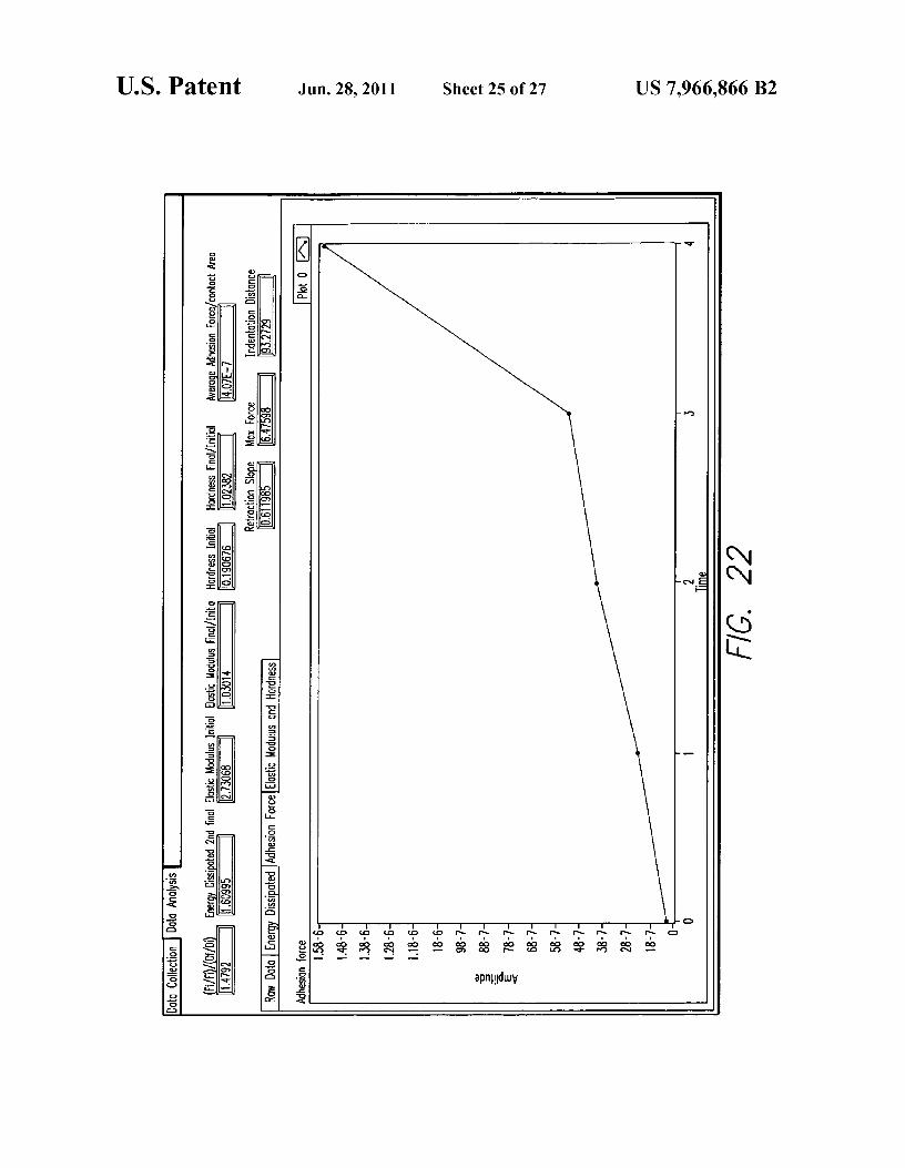
FIG. 22 shows a screenshot of the automated data analysiscurve of Adhesion force as a function of time from the Lab-view program used in the currently preferred embodiment;
FIG. 23 shows a screenshot of the automated data analysiscurves of Elastic Modulus and Hardness as a function of timefrom the Labview program used in the currently preferredembodiment; and
FIG. 24 depicts a generalized measurement head used inthe invention.
DETAILED DESCRIPTION OF THE INVENTION
The essential feature of the invention is a probe that isinserted into a material under test a distance that is measuredrelative to a reference probe, which rests substantially on thesurface of the material under test. In a preferred embodiment,the probe consists of a steel shaft tipped with a sharpeneddiamond. It slips inside a three footed reference probe withfeet on a circle of diameter approximately 1.5 inches. Atypical penetration depth is 0.05 mm.
The method is particularly suited to evaluating one or moreproperties of a living human bone of a subject, the test probebeing inserted through the periosteum and/or soft tissue onthe bone so that the test probe contacts the subject's bone.Such an evaluation is described in our previous work ondeveloping a bone diagnostic Instrument, filed in U.S. patentapplication Ser. No. 11/417,494 filed May 3, 2006 titledMethods and Instruments for Assessing Bone Fracture Risk,the disclosure of which is incorporated herein by reference.
In one class of embodiments, the probe and reference probeare connected to a measurement head. This measurementhead can be connected to a base station either with wires orwith a wireless connection. This measurement head can beheld on the material under test with a stand or it can be handheld or it can be hand held with the help of an optionalsupport. This optional support can, for example, serve to holdthe measurement head at a fixed angle relative to the surfaceof the material under test during the test process.
6The test process consists of one or more indentation cycles
during which the force applied to the probe and the distancethat the probe is inserted into the material under test aremeasured. These measurements can be analyzed to give mate-
5 rial parameters such as Elastic Modulus, Hardness, Adhesion(that is the maximum force needed to pull the probe out of thematerial), Elastic Energy Dissipation, Plastic Energy Dissi-pation, Total Energy Dissipation, Maximum distance ofinsertion, and Maximum Force during the cycle. All of these
io parameters can be measured as a function of time through aseries of cycles. For example, we sometimes measure boneparameters over a series of 80 cycles at 3.5 Hz. Additionaluseful parameters are the ratios of the final to initial values ofthe individual parameters: for example, the ratio of the Plastic
15 Energy Dissipation on the final cycle to the Plastic EnergyDissipation on the first cycle. It has turned out that the ratio ofthe final value of Hardness to the initial value of the Hardnesson bone is correlated with resistance to bone fracture.
FIG. 3 is a detailed drawing of the measurement head of a20 currently preferred embodiment of our invention. A test probe
302 consisting of a shaft 304 and a sharp tip (often a diamond)306 is attached to a shaft 308 that connects to the core 310 ofan LVDT 312 (for example Measurement Specialties MHR025). This in turn connects to a load cell 314 (for example
25 Futek LSB 200) and then, with a shaft 315, to a force genera-tor 316 consisting of two flexures of novel design 318, (whichwill be described in more detail in FIGS. 6, 7 and 8) togetherwith a voice coil actuator (a modified version of BEI KimcoMagnetics LA16-27-000A) which consists of a moving coil
30 320 in a magnetic field assembly 322. The flexures 318 areattached with screws 323. This force generator 316 isanchored in an inner shell 324 that is capped by the flexures318. The force generator 316 is held in an outer shell 326. Theouter shell is connected to a nose piece 328, which supports
35 the LVDT body 312. The position of the LVDT body 312 canbe adjusted to zero or otherwise adjust the signal from theLVDT 310, 312 with a fine screw 330 and is locked into placewith set screws 332. The nose piece 328 also rigidly supportsa reference probe 334 that rests on the surface of the sample
40 under test 336. The measurement head can be hand heldduring the test, which has the advantage that it can be forcedagainst the sample under test with greater force than its ownweight. In general the largest force that can be applied by theforce generator 316 to the sample under test 336 must be less
45 than the force with which the measurement head is pressedagainst the surface. Otherwise the measurement head will liftoff the sample under test 336. This greater force with handheld operation allows greater maximum force during the mea-surement of force vs. distance curves. Hand held operation
5o also allows measurements on surfaces that are not substan-tially horizontal and measured from above. Alternately, elas-tic elements such as springs or rubber tubes or bungee cordscan used to hold the measurement head against the sampleunder test.
55 The electrical signals to actuate the force generator 316 aswell as the force signal from the load cell 314 and the distancesignal from the LVDT 310, 312 pass through an electricalconnector 338 (AMP 28 pin connector). An optional adjust-ment of the initial position of the test probe 302 relative to the
6o reference probe 334 can be made with an optional spring 340that is pulled with an optional screw 342 that is threadedthrough a cap 344. The bandwidth of both the LVDT 310,312and the load cell 314 and both their amplifiers and the dataacquisition system is 1 kHz or above. Thus the instrument can
65 be operated to obtain complete force vs. distance curves incycle times as fast as 0.1 second. For maximum resolution,cycle times as fast as 1 second are more typical. For maximum
US 7,966,866 B27
8speed, cycle times as fast as 0.01 second have been used, but
Input signals are received via electromagnetic radiation
the force vs. distance curve is not accurately captured. Fast
509 by the wireless module 508. The signals are then trans-cycle times can, however, be used to test for damage during mitted to and amplified by the PC board with amplifier 506cyclic loading with, optionally, slower, more accurate curves that drives the force generator 416. The amplified signal istaken before and after the fast cyclic loading. 5 then sent to the force generator 416 in the instrument via the
FIG. 4 is a detailed drawing of another version of the connector 501.measurement head of a currently preferred embodiment of
The whole system, including the instrument, may be pow-
our invention. This version is designed to be used as Bone ered from the rechargeable battery 510. The battery itself hasDiagnostic Instrument (Methods and Instruments forAssess- an energy port 511 where external power can be introduceding Bone Fracture Risk U.S. patent application Ser. No. io into the system to either recharge the battery or power the11,417,494) for which soft tissue overlying the bone must be wireless module externally. The battery 510 may also bepenetrated in order to measure the properties of the underly- wired such that it is easily removable or replaceable. Batteriesing bone. In thi s version the test probe 402 is a sharpened steel
such as found in small hand tools such as cordless drills are
rod of diameter 0.015" held in a mounting pin 404 which
suitable. For the force generator 416 in the currently preferredattaches magnetically to a permanent magnet 406 that is 15 embodiment, we typically use average currents of less thanattached to a shaft 408 that connects to the core 410 of an
IA at voltages of a few Volts for times of order 20s thus
LVDT 412 (for example Measurement Specialties MHR
requiring of order 0.0056 Ah per test. This can easily be025). This in turn connects to a load cell 414 (fox example the supplied by the type of NiMH rechargeable batteries used inFutek LSB 200 or the Sensotec Model 34 precision miniature cordless drills, which can supply 3 Ah, enough for over 500load cell) and then to a force generator 416 consisting of two 20 tests.flexures of novel design 418, which will be described in more
The wireless adapter/power pack module 500 can (option-
detail in FIGS. 6, 7 and 8) together with a voice coil actuator ally) also contain a keypad 512 to set test parameters and(a modified version of BEI Kimco Magnetics LA16-27- access selected test data and analysis on a display screen 514.000A) which consists of a moving coil 420 in a magnetic field
For wireless use, the switch 516 can be added to the measure-
assembly 422. This force generator 416 is anchored in an 25 ment head 503 (shown in more detail in FIGS. 3 and 4) toinner shell 424 that is capped by the flexures 418. The force trigger test cycles conveniently.generator 416 is held in an outer shell 426. The outer shell is
The measurement head 503 is connected to the wireless
connected to a nose piece 428, which supports the LVDT
adapter/power pack module 500 with cable 518. As shown inbody 412. Theposition of the LVDT body 412 canbe adjusted
FIG. 5A, the cable can be external, joining the measurement
to zero or otherwise adjust the signal from the LVDT 410,412 3o head 503 to the wireless adapter/power pack module 500 thatwith a fine screw 430 and is locked into place with set screws
is mounted on top of the measurement head. This permits the
432. The nose piece 428 also rigidly supports a reference removal of the wireless adapter/power pack module 500 if itprobe 434 that rests on the surface of the sample under test
is desired to have the measurement head connected directly to
336. In this version the reference probe 434 consists of small
control electronics and a computer. If the unit is designed onlydiameter stainless steel tubing 436 held in a brass body 438 35 for wireless use, the cable can, of course, be internal. Alter-that is threaded into the nose piece 428 and held rigidly in nately the wireless adapter/power pack module 500 can beposition with a knurled locking nut 440
separate from the measurement head 503 as shown in FIG.
The electrical signals to actuate the force generator 416 as
5B. This has the advantage of making the hand held partwell as the force signal from the load cell 414 and the distance
lighter and the wireless adapter/power pack module 500 more
signal from the LVDT 410, 412 pass through an electrical 40 capable in terms of battery capacity, data processing and dataconnector 442 (AMP 28 pin connector). An optional adjust- storage.ment of the initial position of the test probe 402 relative to the
FIGS. 6A-6C show the circular flexures used in the cur-
reference probe 434 can be made with an optional spring 444
rently preferred embodiment of the invention. The flexuresthat is pulled with an optional screw 446 that is threaded
are included to guide the motion of the force generator (for
through a cap 448. 45 example 416, FIG. 4) and ensure that there is no substantialFIGS. 5A and 5B shows how the currently preferred
off-axis motion. The flexures design consists of a large, hori-
embodiments of our invention can be made wireless. The zontal, thin inner membrane 602 connected to a outer, thin,measurement head 503 (shown in more detail in FIGS. 3 and
horizontal membrane 604 through a vertical ring 606. The
4) is combined with a wireless adapter/power pack module
design of the flexures was improved through the use of finite500 for the instrument. This module 500 has many functions 50 element analysis. FIG. 7 shows the results of simulating theincluding: supplying power for the instrument, amplifying
deformation of one of the flexures under an axial load.
and conditioning the signals from the transducers, the trans- The softness of the circular flexure may be increased bymission of data, the reception of input signals, and the ampli- cutting out radial sections 802 of the flexure, as shown infication of input signals. FIGS. 8A-8C. Further softening could be achieved by cutting
The transmission of the data starts at the connector 501, 55 away more of the circular flexure, for example, leaving onlywhere the interface with the instrument is located. The signal
thin radial strips like spokes on a wheel.
for the distance sensor (from the instrument) is sent through
FIGS. 9A-9E show various reference probes that can bethe connector 501 to the PC board with distance sensor ampli- used in place of the reference probe 334 shown in FIG. 3.9Afier and signal conditioner 504. Here the signal is amplified
has three rounded feet 900 to minimize marring of the mate-
and then sent to the wireless module 508. The data is then sent 6o rial under test. 9B has three pointed feet 902 to minimizeto the partner computer(s) 513 (FIG. 513) with electromag- lateral slipping. 9C has three adjustable feet 904 that containnetic radiation 509. The signal from the load cell (from the permanent magnets 906 to minimize slipping and marring ofinstrument) goes through the connector 501 to the PC board
magnetic surfaces such as steel. These magnets 906 could
with load cell amplifier and signal conditioner 502. Here the also be electromagnets or mechanically switchable magnetssignal is amplified and conditioned and then sent to the wire- 65 as used in magnetic bases (see, for example, 1228 in FIG. 12).less module 508 where it is transmitted to the partner com- 9D shows one of many possible variants of fixed 908 andputer(s) 513 with electromagnetic radiation 509. adjustable feet 910. The motion of the adjustable foot 910 is

US 7,966,866 B29
10demagnified at the location of the test probe 912 to give more cations, however, it is useful to supplement or eliminate theprecise positioning. 9E shows a reference probe that is suit- hand holding the instrument. The goal is to stabilize theable for use with a standard diamond indenter 914. As an
instrument more than is possible when just hand held. As
example, a Rockwell Diamond Indenter with a Versitron some examples, the measurement head 1202 is attached withshank 914 is shown, but, of course many others could be used 5 a removable mount 1204 (for example, a '/4-20 screw mountwith a suitably designed reference probe. such as used for cameras) to a rail 1206 which is, in turn held
FIG. 10 shows different possibilities for the tips of test
in a guide block 1208 (for example, the Miniature Corrosion-probes. Test probe 1000 is patterned on the diamond indenter
Resistant Versa-Mount Guide Blocks and Rails form Mc
used in Knoop hardness testing. It has a pyramid-shaped
Master Carr can be used) which is, in turn, attached with adiamond 1002 with apical angles of 130° and about 170°, io removable mount 1210 (for example, a '/4-20 screw mountmounted on a tungsten carbide shank 1004. Test probe 1006, such as used for cameras can be used here also) to a supporthas a diamond 1008 in the shape of a square-based pyramid
arm 1212 attached to a base 1214. This support stand allows
whose opposite sides meet at the apex at an angle of 136° as the measurement head 1202 to move freely up and downused in Vickers hardness testing of metals and ceramics, while being constrained laterally and held vertically.mounted on a ceramic shaft 1010. Test probe 1012 is a disk 15 The measurement head 1216 is also mounted via a remov-that can be rotated for measuring friction, ^=0, or viscosity of
able mount 1218 to a rail 1220 which is, in turn held in a guide
tissue near a bone surface, at ^-0 or 0>0 as in conventional
block 1222 (for example, the Miniature Corrosion-Resistantviscosity measurements. Test probe 1014 is wedge shaped
Versa-Mount Guide Blocks and Rails from Mc Master Carr
and is used for assessing the fracture resistance of materials. can be used) which is, in turn, attached with a removableTest probe 1016, designed for testing the material properties 20 mount 1224 (for example, a'/4-20 screw mount such as usedof bone and teeth, has a cone at its end. In a preferred embodi- for cameras can be used here also) to an adjustable arm 1226ment 0=90 and the test probe is tool steel. In other embodi- attached to a magnetic base 1228.ments the test probe can have angles 0=70 and 50 and can
The measurement head 1230 is permanently mounted by
have a tip 1018 of a different material, such as diamond. Test attachments at each end to a rail 1232, which is, in turn,probe 1020 is patterned after the indenters used in some 25 mounted to an articulating arm system 1234 (such as theRockwell and Brinell hardness testing, and has a half sphere
F1exArm available from Midwest Specialties Inc.). The probe
of tungsten carbide 1022 bonded to a steel shank 1024. Test assembly 1236 is shown schematically penetrating soft tissueprobe 1026 is a tube that can be rotated for measuring friction of a leg 1238 to reach the tibia 1240. The leg is held in aon the surface of a material. Test probe 1028 is a screw that modified V block 1242 to stabilize it during the measure-can test bone by measuring the torque necessary to screw it 30 ments.into the bone. These are only intended as representative
The measurement head 1244 is held in a microscope stand
examples. Many other geometries and test probe materials
1246. The material under test is in a fluid cell 1248 that iscould be used. filled with fluid 1250. One of the advantages of all the
FIG. 11 shows details of three probe assemblies (test embodiments shown is that it is easy to work with samplesprobes in reference probes) in the top row. In the first 35 under aqueous buffers to, for example, simulate physiologicalexample, the test probe 1102 is held in a mounting pin 1104
conditions. It is also easy to put in a heating stage or hotplate
that is a '/i6' diameter steel rod with a hole in the end into under the fluid cell 1248 or under a material under test that iswhich the test probe is glued or soldered. The reference probe not in a fluid cell because there is no rigid frame that limits the1106 is composed of sharpened, small diameter tubing 1108
space below the measurement head. Though FIG. 12 shows a
joined to a threaded body 1110. In the second example, the 40 particular microscope stand 1246, a wide variety of micro-test probe 1112 is shorter, but, when mounted on a longer scope stands are available for mounting stereo microscopesmounting pin 1114, gives the same overall length of mounted
including ones for operating rooms that roll on the floor and
test probe as the previous example. In this case the reference allow the surgeon to see parts of a patient's body on theprobe is a hypodermic syringe needle 1116 that is removably operating table. This type of rolling microscope stand couldmounted in a threaded Luer adaptor 1118. In the third 45 hold the measurement head 1244 for testing the bone or teethexample, the test probe 1120 is mounted in a mounting pin of a patient on a table. The core assemble is mounted in a disk1122. Here the reference probe 1124 has no tubing projecting of the correct diameter for the particular microscope standfrom the end, but is suitable for use when the material under
(typically about 3" in diameter). This mounting in the disk can
test is not covered with a layer that must be penetrated (as in
be rigid (as shown) or via a rail and guide block system asthe case of skin covering bone). 50 shown in the other support stands. Conversely the other sup-
FIG. 11 also shows, in the bottom row, some details of an port stands can be used without a rail and guide block system.alternate to the magnet shown as 406 in FIG. 4 for holding
The advantage of the rail and guide block system is that the
mounted test probes. The collet 1126 holds the mounting pin
force of the probe assembly on the material under test is1128 for the test probe 1130. This collet 1126 is attached to a constant: the weight of the moving parts (for example theshaft 1132, shown as 408 in FIG. 4. The collet 1134 holds the 55 measurement head 1202, the removable mount 1204 and thetest probe 1136 directly. The tube 1138, which can optionally rail 1206).be attached to the test probe 1136, functions to minimize
FIG. 13 shows a previous embodiment of this invention.
buckling of the test probe 1136. The collet 1140 holds a tube
The position of the test probe 1302 relative to the reference1142 in which the test probe 1144 is mounted. probe 1304 can be coarsely adjusted by screwing the threaded
Finally, the magnet 1146 holds the mount 1148 for the test 6o Luer adaptor 1306 into or out of the frame arm 1308. Fineprobe 1150. This test probe and all the test probes in FIG. 11
adjustment comes from turning the screw 1310 with the knob
can have many tip shapes, as shown in FIG. 10. 1312. The frame arm 1308 is held against the tip of the screwFIG. 12 shows various support stands for the instrument. 1310 by a spring 1314. In this embodiment the force and
The instrument can be hand held, resting on the three feet of
motion are generated by a transducer 1316 (Clark Tactilethe reference probe 334 that rest on the surface of the sample 65 Sound Transducer, U.S. Pat. No. 5,473,700) that consists ofunder test 336 shown in FIG. 3. More reference probes for two dome shaped disks that are joined at their edges. Onehand held use were shown in FIGS. 9A-9E. For some appli- supports a voice coil and the other supports a magnet struc-

US 7,966,866 B211
12ture. This figure illustrates that the force generator of this via flexures 1524 as shown above (as 1514) but rotated 90invention is not restricted to just the type of voice coil system
degrees around the axis of the lower wire 1520 so the flexures
shown in the other figures. Other alternatives for a force are not as visible as above. These flexures 1524 are mountedgenerator have been shown in FIG. 13 of Methods and Instru- on a movable stage 1526 that slides on two rods 1528 andments for Assessing Bone Fracture Risk U.S. patent applica- 5 1530. This movable stage can be moved by turning the knobtion Ser. No. 11,417,494). This embodiment used a load cell
1532 whichturns the screw 1534 which connects the movable
1318 and an optical position detector 1320. stage 1526 to frame element 1536 which is held stationaryFIGS. 14A and 14B show two embodiments of this inven- relative to the magnet structure 1504 and the rods 1528 and
tion. These embodiments are based on a commercially avail- 1530. Thus turning the knob 1532 lowers the shaft 1508 andable compact positioning system (VCS-10 Voice Coil Linear io the test probe 1538 relative to the reference probe 1540. InStage from Equipment Solutions, Inc.) In the left embodi- this embodiment the force sensor 1542 is again a load cell.ment the test probe 1402 is held in amounting pin 1404 which
The position sensor 1544 was optical. A capacitance sensor
attaches magnetically to a permanent magnet 1406 that is
for position could also be used in this and other embodiments.attached to a shaft 1408 on which is mounted an arm 1410
FIG. 16A shows the force measurement for a cyclic inden-
whose motion is detected by the optical position detector 15 tation cycle test on PMMA taken with the invention as1412. The shaft 1408 continues to a load cell 1414 and then to
described in FIG. 13. The corresponding distance measure-
a support block 1416 that is screwed to the movable platform ment over the same set of indentation cycles is shown in FIG.1418 of a one axis stage with a guide block 1420 under the
16B. FIG. 16C shows a single indent-retract cycle on PMMAplatform 1418. The force and motion are generated by a voice taken with the invention as described in FIG. 15. The loadingcoil in magnet structure 1424. In the right embodiment a shaft 20 cycle consists of an indentation at a fixed rate of voltage drive1426 is directly mounted in support block 1416. In this case
increase to the force generator, a pause at fixed voltage drive
the force is monitored as proportional to the current to the to the force generator, and a retraction at a fixed rate of voltagevoice coil 1428. In practice this is very close to being an
drive decrease to the force generator.
accurate proportionality. If necessary, however, it can be cor- FIG. 17A and FIG. 17B show respectively the measuredrected with a correction factor of the moving mass times the 25 maximum indentation distance and maximum force afteracceleration. For example, for a moving mass of 0.1 kg and a pausing at the maximum drive to the force generator. Themaximum acceleration of 100 microns in ten milliseconds, pause is included to reduce the effect of viscoelasticity onthe maximum force correction would be of order) 0.1 kgx100
measurements of the retraction slope and thus the increase the
microns/(0.01 sec) 2-0.1 Newton. Since the embodiment in accuracy of the measured elastic modulus. FIG. 17C shows aFIG. 14B does not have the compliance of the load cell 1414 30 linear fit to the initial part of the retraction curve, called theto deal with, the motion of the test probe can be monitored
retraction slope, which may be used as a material character-
using the built in position detector 1430 in the VCS-10 Voice
ization parameter, or in subsequent analysis to determine theCoil Linear Stage from Equipment Solutions, Inc. Alter- elastic modulus of the sample. FIG. 17D shows the first andnately, higher position resolution can be achieved with a high
last indent-retract cycles for a series of several indentations
resolution LVDT (for example Measurement Specialties 35 taken with the invention as described in FIG. 15, plottedMHR 025) or other supplemental distance detectors such as together for comparison purposes. Change in any measuredcapacitance sensors, optical beam deflection detectors, or property over a series of indentation cycles may be measured,laser interferometers to measure the motion of the movable as illustrated in FIG. 17E. The change in maximum force isplatform 1418 and thus the test probe 1402 relative to the measured between the first and last indentation cycles over areference probe 1432, which is stationary relative to the guide 40 series of 30 cycles. FIG. 17F shows the measurement of workblock 1420, which is attached to the case 1434 on which the
during the indent-retract cycle that may be used to character-
mount 1436 for the reference probe is attached. Thus the body
ize a sample. The area beneath the loading and pause cycle isof the LVDT or other distance detector would be fastened to quantified as the work of indentation. The elastic energythe case 1434 and the core of the LVDT would be attached to recovery is defined as the area beneath the retraction curve.the test probe. 45 The difference between the work of indentation and the elas-
This commercial unit can also be used in feedback mode to tic recovery is defined as the energy dissipated in the indent-run the invention with position control. In this case, for retract cycle.example, the force needed to indent the material under test to
FIG. 18 (prior art) shows the measured parameters that are
a fixed maximum depth could be monitored as a function of
pertinent to the measurement of elastic modulus and hardnesscycle number. This was not, however, our preferred embodi- 50 in the invention. The variables and equations used in thement because the force and position noise with the VCS-10
calculation are listed. The analysis method used is that of
Voice Coil Linear Stage and the SCAS24 Linear Servo Con- Oliver and Pharr (ref. W. C. Oliver and G. M. Pharr. Measure-troller were much larger than in our preferred embodiment. ment of hardness and elastic modulus by instrumented inden-We believe that some of the problem was due to friction in the tation: Advances in understanding and refinements to meth-one axis stage. Feedback can be more easily used with the 55 odology. J. Mater. Res. 19 (2004), 3. (review article)).much smaller friction from flexures such as in the other
The operation of the invention is aided by computer inter-
embodiment shown in this document. We note that feedback
facing. FIG. 19 shows a screenshot of the Labview programcontrol could also be used to run in a force controlled mode. used to run the invention. The force and distance measure-
FIG. 15 shows another previous embodiment of this inven- ments are collected andplotted bothversus time and as a forcetion. In this embodiment the flexure support of the voice coil 60 versus distance graph in real-time. There are several control-1502 in the magnet structure 1504 is provided by two wires. lable parameters to alter the indentation protocol, including:The upper wire 1506 attaches to the shaft 1508 with a cylin- indentation frequency, indentation amplitude, number ofdrical block 1510. The outer ends of the upper wire 1506 are
indent cycles, and the half-angle of the conical indenter,
attached to blocks 1512 which are, in turn, mounted on flex- called the probe half angle.ures 1514 which are, in turn, mounted, with blocks 1516 to 65 Automated data analysis upon completion of the indenta-the support shell 1518. The lower wire 1520 attaches to the tion cycles is achieved through the computer interface. Ashaft 1508 with blocks 1522. These blocks 1522 are mounted
screenshot of the current data analysis interface is shown in

US 7,966,866 B213
FIG. 20. The main analysis screen shows several measuredquantities that may be used to characterize a material, as wellas the raw force and distance data, the identified transitionpoints in each indent-retract cycle, and a comparison of thefirst and last indentation curves for multiple-cycle testing.FIG. 21, FIG. 22 and FIG. 23 show additional analysis screen-shots of the change in the measured energy dissipated, thechange in maximum adhesion force during retraction, and thechange in both elastic modulus and hardness as a function oftime through the cyclical test.
FIG. 24 shows a generalized measurement head for thisinvention. The test probe 2402 consisting of a shaft 2404 anda sharp tip (often a diamond) 2406 is attached to a shaft 2408which is, in turn, connected to an optional torque and angulardisplacement sensor 2410 then to an optional torque genera-tor 2412, then to an optional linear displacement sensor 2414,then to an optional force sensor 2416, and finally to anoptional force generator 2418. The reference probe 2420 isconnected to the housing 2422 that holds the transducers andgenerators. The housing 2422 could be supported and posi-tioned on the sample under test by a support such as thosedrawn in FIG. 12. The optional torque and angular displace-ment sensor 2410 together with the optional torque generator2412 can be used to measure friction with test probes such as1012, 1022 and 1026 (FIG. 10) or the torque necessary toscrew a test probe like 1028 (FIG. 10) in or out of a materialunder test. This might, for example, be useful in determiningwhether a patient's bone is suitable for holding screws formounting orthopedic appliances. With the optional force sen-sor 2416 and the optional force generator 2418 the force topull out a screw could be measured as a test of bone quality.
Although the present invention has been described in con-nection withthe preferred embodiments, it is to be understoodthat modifications and variations may be utilized withoutdeparting from the principles and scope of the invention, asthose skilled in the art will readily understand. Accordingly,such modifications may be practiced within the scope of thefollowing claims.
REFERENCES
The following references are each incorporated herein byreference.
1.W. C. Oliver and G. M. Pharr. Measurement of hardnessand elastic modulus by instrumented indentation: Advancesin understanding and refinements to methodology. J. Mater.Res. 19 (2004), 3.
2. C. A. J. Putman, H. G. Hansma, H. E. Gaub, and P. K.Hansma, Langmuir 8, 3014 (1992).
143. Briscoe, B. J. and Sebastian, K. S. An analysis of the
durometer indentation. Rubber Chemistry and Technology 66(5): 827-836 1993).
4. James B. Thompson et al., Nature 414, 774, 13 Dec.5 2001.
5. Paul K. Hansma, Patricia J. Turner, and Georg E. Fant-ner, Bone Diagnostic Instrument, REVIEW OF SCIENTIFICINSTRUMENTS 77, 075105 (2006).
6. U.S. Pat. Nos. 1,770,045, 5,450,745, 5,463,897, 5,473,700, 6,142,010, and 6,405,599, and U.S. Patent Publication
io Nos. 2002/0170360 and 2005/0262685.7. U.S. patent application Ser. No. 11/417,494 filed May 3,
2006 titled Methods and Instruments for Assessing BoneFracture Risk.
8. "Micro Hardness Tester (MHT) for fracture toughnessis determination of brittle materials", No. 8, July 1998.
9. CSM Indentation Testers, four page brochure.10. ASTM Proposed Instrumented Indentation Testing
Standard", pages 1-4, October 2003.The invention claimed is:
20 1. An instrument for characterizing a material comprising:a housing;a test probe and a reference probe aligned in the housing,
the test probe constructed for insertion into the materialto indent the material;
25 a force generator;a flexure configured to guide the motion of the force gen-
erator; anda force sensor operatively coupled to the test probe for
determining a force versus distance parameter by mea-so during the force needed to insert the test probe a prede-
termined distance or as a function of distance into thematerial.
2. The instrument of claim 1, wherein the force generatorcomprises a moving coil disposed in a magnetic field assem-
ss bly.3. The instrument of claim 1, wherein the reference probe
is in the form of a sheath in which the test probe is disposed,the distal end of the reference probe being proximal to a tip of
40 the test probe.
4. The instrument of claim 1, wherein the flexure comprisesa first, inner membrane and a second, outer membrane con-nected to the first, inner membrane.
5. The instrument of claim 4, wherein the first, inner mem-45 bran is connected to the second, outer membrane via a ring.
6. The instrument of claim 1, further comprising a distancesensor.
7. The instrument of claim 6, wherein the distance sensorcomprises a linear variable differential transformer.