
United States Office of Air and Radiation EPA 402-R-96 … Assignment Manager for this guide. ......
203
United States Office of Air and Radiation EPA 402-R-96-017 Environmental Protection Office of Solid Waste and Agency Emergency Response Washington, DC 20460 November 1996 Technology Screening Guide for Radioactively Contaminated Sites
Transcript of United States Office of Air and Radiation EPA 402-R-96 … Assignment Manager for this guide. ......

United States Office of Air and Radiation EPA 402-R-96-017Environmental Protection Office of Solid Waste andAgency Emergency Response
Washington, DC 20460
November 1996
Technology ScreeningGuide for RadioactivelyContaminated Sites


EPA 402-R-96-017November 1996
TECHNOLOGY SCREENING GUIDE FOR RADIOACTIVELY CONTAMINATED SITES
Prepared for
U.S. Environmental Protection AgencyOffice of Air and Radiation
Office of Radiation and Indoor AirRadiation Protection Division
Center for Remediation Technology and Tools
and
U. S. Environmental Protection AgencyOffice of Solid Waste and Emergency Response
Prepared Under:
Contract No.68-D2-0156


iii
DISCLAIMER
Mention of trade names, products, or services does not convey, and should not be interpretedas conveying, official EPA approval, endorsement, or recommendation.

iv
ACKNOWEDGEMENTS
Edward Feltcorn of ORIA’s Center for Remediation Technology and Tools was the EPAWork Assignment Manager for this guide. Assistance in production of this guide wasprovided by Jack Faucett Associates (Barry Riordan - Project Manager) under EPA ContractNumber 68-D2-0156.
EPA/ORIA wishes to thank the following individuals for their assistance and technical reviewcomments on the drafts of this report:
Doug Bell, EPA/ SuperfundDr. Walter Kovalick, Jr., EPA Technology Innovation OfficePaul Giardina, EPA Region 2Paul Leonard, EPA Region 3Nancy Morlock, EPA Region 6Linda Meyer, EPA Region 10 Ed Barth, EPA/ORD CincinnatiGregg Dempsey, EPA/ORIA Las Vegas FacilitySam Windham and Samuel Keith, EPA/ORIA NAREL
EPA/ORIA would like to extend special appreciation to Thomas Sorg of EPA/ORDCincinnati, without his assistance the section on liquid media would have not been complete.
In addition, the following staff from ORIA’s Remediation Technology and Tools Centerassisted in the development, production and review of this document:
Nick Lailas, DirectorRon Wilhelm Tri HoangCarey Johnston

v
TO COMMENT ON THIS GUIDE OR PROVIDE INFORMATION FOR FUTUREUPDATES:
Send all comments/updates to:
US Environmental Protection AgencyAttention: Technology Screening Guide for RadContaminated Sites401 M St SW (6602J)Washington, DC 20460
orEd FeltcornEmail: [email protected]: 202-233-9350 Fax: 202-233-9650


vii
TABLE OF CONTENTS
PAGELIST OF ACRONYMS . . . . . . . . . . . . . . . . . . . . . . . . . . . . . . . . . . . . . . . . . . . . . . . . . . . . . . . . . . . . . . . . . . . . . . xi
EXECUTIVE SUMMARY . . . . . . . . . . . . . . . . . . . . . . . . . . . . . . . . . . . . . . . . . . . . . . . . . . . . . . . . . . . . . . . . . . xiii
SECTION I: INTRODUCTION . . . . . . . . . . . . . . . . . . . . . . . . . . . . . . . . . . . . . . . . . . . . . . . . . . . . . . . . . . . . . . 1
1.1 Purpose . . . . . . . . . . . . . . . . . . . . . . . . . . . . . . . . . . . . . . . . . . . . . . . . . . . . . . . . . . . . . . . . . . . . . . . . . . . 1
1.2 Background . . . . . . . . . . . . . . . . . . . . . . . . . . . . . . . . . . . . . . . . . . . . . . . . . . . . . . . . . . . . . . . . . . . . . . . 2
1.3 General Information Related to Radioactively Contaminated NPL Sites . . . . . . . . . . . . . . . . . . . 41.3.1 Types of Sites . . . . . . . . . . . . . . . . . . . . . . . . . . . . . . . . . . . . . . . . . . . . . . . . . . . . . . . . . . . . 41.3.2 Characteristics of Radioactively Contaminated NPL Sites . . . . . . . . . . . . . . . . . . . . . 41.3.3 General Remedial Response Actions . . . . . . . . . . . . . . . . . . . . . . . . . . . . . . . . . . . . . . . . 8
1.4 Technical Approach Used . . . . . . . . . . . . . . . . . . . . . . . . . . . . . . . . . . . . . . . . . . . . . . . . . . . . . . . . . . . 91.4.1 Technologies Presented . . . . . . . . . . . . . . . . . . . . . . . . . . . . . . . . . . . . . . . . . . . . . . . . 91.4.2 Approach to Evaluating Technologies . . . . . . . . . . . . . . . . . . . . . . . . . . . . . . . . . . 101.4.3 Summary of Selected Technologies . . . . . . . . . . . . . . . . . . . . . . . . . . . . . . . . . . . . . 12
1.5 Organization of this Guide . . . . . . . . . . . . . . . . . . . . . . . . . . . . . . . . . . . . . . . . . . . . . . . . . . . . . . . . . 19
SECTION II: SOLID MEDIA TECHNOLOGY PROFILES . . . . . . . . . . . . . . . . . . . . . . . . . . . . . . . . . . . . . 23
Containment . . . . . . . . . . . . . . . . . . . . . . . . . . . . . . . . . . . . . . . . . . . . . . . . . . . . . . . . . . . . . . . . . . . . . . . . . . . 252.1 Capping . . . . . . . . . . . . . . . . . . . . . . . . . . . . . . . . . . . . . . . . . . . . . . . . . . . . . . . . . . . . . . . . . . . . . . . . . 272.2 Land Encapsulation . . . . . . . . . . . . . . . . . . . . . . . . . . . . . . . . . . . . . . . . . . . . . . . . . . . . . . . . . . . . . . . 352.3 Cryogenic Barriers . . . . . . . . . . . . . . . . . . . . . . . . . . . . . . . . . . . . . . . . . . . . . . . . . . . . . . . . . . . . . . . . 432.4 Vertical Barriers . . . . . . . . . . . . . . . . . . . . . . . . . . . . . . . . . . . . . . . . . . . . . . . . . . . . . . . . . . . . . . . . . . . 51
Solidification/Stabilization . . . . . . . . . . . . . . . . . . . . . . . . . . . . . . . . . . . . . . . . . . . . . . . . . . . . . . . . . . . . . . . 612.5 Cement Solidification/Stabilization . . . . . . . . . . . . . . . . . . . . . . . . . . . . . . . . . . . . . . . . . . . . . . . . . 632.6 Chemical Solidification/Stabilization . . . . . . . . . . . . . . . . . . . . . . . . . . . . . . . . . . . . . . . . . . . . . . . . 71
Chemical Separation . . . . . . . . . . . . . . . . . . . . . . . . . . . . . . . . . . . . . . . . . . . . . . . . . . . . . . . . . . . . . . . . . . . . 792.7 Solvent/Chemical Extraction . . . . . . . . . . . . . . . . . . . . . . . . . . . . . . . . . . . . . . . . . . . . . . . . . . . . . . . 81
Physical Separation . . . . . . . . . . . . . . . . . . . . . . . . . . . . . . . . . . . . . . . . . . . . . . . . . . . . . . . . . . . . . . . . . . . . . 892.8 Dry Soil Separation . . . . . . . . . . . . . . . . . . . . . . . . . . . . . . . . . . . . . . . . . . . . . . . . . . . . . . . . . . . . . . . . 912.9 Soil Washing . . . . . . . . . . . . . . . . . . . . . . . . . . . . . . . . . . . . . . . . . . . . . . . . . . . . . . . . . . . . . . . . . . . . . 992.10 Flotation . . . . . . . . . . . . . . . . . . . . . . . . . . . . . . . . . . . . . . . . . . . . . . . . . . . . . . . . . . . . . . . . . . . . . . . . 109
Vitrification . . . . . . . . . . . . . . . . . . . . . . . . . . . . . . . . . . . . . . . . . . . . . . . . . . . . . . . . . . . . . . . . . . . . . . . . . . . 1192.11 In-situ Vitrification . . . . . . . . . . . . . . . . . . . . . . . . . . . . . . . . . . . . . . . . . . . . . . . . . . . . . . . . . . . . . . . 1212.12 Ex-situ Vitrification . . . . . . . . . . . . . . . . . . . . . . . . . . . . . . . . . . . . . . . . . . . . . . . . . . . . . . . . . . . . . . . 129

viii
TABLE OF CONTENTS(continued)
PAGE
SECTION III: LIQUID MEDIA TECHNOLOGY PROFILES . . . . . . . . . . . . . . . . . . . . . . . . . . . . . . . . . 137
Chemical Separation . . . . . . . . . . . . . . . . . . . . . . . . . . . . . . . . . . . . . . . . . . . . . . . . . . . . . . . . . . . . . . . . . . . 1393.1 Ion Exchange & Chemical Precipitation . . . . . . . . . . . . . . . . . . . . . . . . . . . . . . . . . . . . . . . . . . . . . 141
Physical Separation . . . . . . . . . . . . . . . . . . . . . . . . . . . . . . . . . . . . . . . . . . . . . . . . . . . . . . . . . . . . . . . . . . . . 1513.2 Membrane Processes, Carbon Adsorption, and Aeration . . . . . . . . . . . . . . . . . . . . . . . . . . . . . . 153
APPENDIX A: Radioactive Contamination: Basic Concepts and Terms . . . . . . . . . . . . . . . . . . . . . . . . . A-1
APPENDIX B: Bibliography . . . . . . . . . . . . . . . . . . . . . . . . . . . . . . . . . . . . . . . . . . . . . . . . . . . . . . . . . . B-1

ix
LIST OF EXHIBITS
PAGE
Exhibit ES-1: Demonstrated Remediation Technologies for Prevalent Radionuclides at RadioactivelyContaminated Sites . . . . . . . . . . . . . . . . . . . . . . . . . . . . . . . . . . . . . . . . . . . . . . . . . . xv
Exhibit 1-1: Isotope Distribution at Radioactively Contaminated NPL Sites . . . . . . . . . . . . . . . . . 5Exhibit 1-2: NPL Sites by Media Contaminants . . . . . . . . . . . . . . . . . . . . . . . . . . . . . . . . . . . . . . 5Exhibit 1-3: NPL Sites and Radionuclides Detected . . . . . . . . . . . . . . . . . . . . . . . . . . . . . . . . . . . 6Exhibit 1-4: NCP Evaluation Criteria Included in Technology Profiles . . . . . . . . . . . . . . . . . . . . 11Exhibit 1-5: Summary of Solid and Liquid Media Technologies . . . . . . . . . . . . . . . . . . . . . . . . . 13Exhibit 1-6: Solid Media Technology Categories . . . . . . . . . . . . . . . . . . . . . . . . . . . . . . . . . . . . 20Exhibit 1-7: Using the Technology Profiles . . . . . . . . . . . . . . . . . . . . . . . . . . . . . . . . . . . . . . . . . 21Exhibit 2-1: Capping Diagram . . . . . . . . . . . . . . . . . . . . . . . . . . . . . . . . . . . . . . . . . . . . . . . . . . . 28Exhibit 2-2: Technical Characteristics Of Capping . . . . . . . . . . . . . . . . . . . . . . . . . . . . . . . . . . . 29Exhibit 2-3: NCP Criteria For Capping . . . . . . . . . . . . . . . . . . . . . . . . . . . . . . . . . . . . . . . . . . . . 33Exhibit 2-4: Land Encapsulation Diagram . . . . . . . . . . . . . . . . . . . . . . . . . . . . . . . . . . . . . . . . . . 36Exhibit 2-5: Technical Characteristics Of Land Encapsulation . . . . . . . . . . . . . . . . . . . . . . . . . . 37Exhibit 2-6: NCP Criteria For Land Encapsulation . . . . . . . . . . . . . . . . . . . . . . . . . . . . . . . . . . . 41Exhibit 2-7: Cryogenic Barriers Diagram . . . . . . . . . . . . . . . . . . . . . . . . . . . . . . . . . . . . . . . . . . 44Exhibit 2-8: Technical Characteristics of Cryogenic Barriers . . . . . . . . . . . . . . . . . . . . . . . . . . . 45Exhibit 2-9: NCP Criteria for Cryogenic Barriers . . . . . . . . . . . . . . . . . . . . . . . . . . . . . . . . . . . . 49Exhibit 2-10: Vertical Barriers Diagram . . . . . . . . . . . . . . . . . . . . . . . . . . . . . . . . . . . . . . . . . . . . 53Exhibit 2-11: Technical Characteristics of Vertical Barriers . . . . . . . . . . . . . . . . . . . . . . . . . . . . . 53Exhibit 2-12: NCP Criteria for Vertical Barriers . . . . . . . . . . . . . . . . . . . . . . . . . . . . . . . . . . . . . . 58Exhibit 2-13: Ex-Situ Solidification/Stabilization . . . . . . . . . . . . . . . . . . . . . . . . . . . . . . . . . . . . . 62Exhibit 2-14: In-Situ Solidification/Stabilization . . . . . . . . . . . . . . . . . . . . . . . . . . . . . . . . . . . . . . 62Exhibit 2-15: Technical Characteristics of Cement Solidification/Stabilization . . . . . . . . . . . . . . . 64Exhibit 2-16: NCP Criteria for Cement Solidification/Stabilization . . . . . . . . . . . . . . . . . . . . . . . . 69Exhibit 2-17: Technical Characteristics of Chemical Stabilization/Solidification . . . . . . . . . . . . . 72Exhibit 2-18: NCP Criteria for Chemical Stabilization/Solidification . . . . . . . . . . . . . . . . . . . . . . 76Exhibit 2-19: Solvent Extraction Diagram . . . . . . . . . . . . . . . . . . . . . . . . . . . . . . . . . . . . . . . . . . . 82Exhibit 2-20: Technical Characteristics of Solvent/Chemical Extraction . . . . . . . . . . . . . . . . . . . . 83Exhibit 2-21: NCP Criteria for Solvent/Chemical Extraction . . . . . . . . . . . . . . . . . . . . . . . . . . . . . 88Exhibit 2-22: Dry Soil Separation Diagram . . . . . . . . . . . . . . . . . . . . . . . . . . . . . . . . . . . . . . . . . . 91Exhibit 2-23: Technical Characteristics of Dry Soil Separation . . . . . . . . . . . . . . . . . . . . . . . . . . . 92Exhibit 2-24: NCP Criteria for Dry Soil Separation . . . . . . . . . . . . . . . . . . . . . . . . . . . . . . . . . . . . 96Exhibit 2-25: Soil Washing Diagram . . . . . . . . . . . . . . . . . . . . . . . . . . . . . . . . . . . . . . . . . . . . . . . 98Exhibit 2-26: Technical Characteristics of Soil Washing . . . . . . . . . . . . . . . . . . . . . . . . . . . . . . . . 99Exhibit 2-27: NCP Criteria for Soil Washing . . . . . . . . . . . . . . . . . . . . . . . . . . . . . . . . . . . . . . . 106Exhibit 2-28: Flotation Diagram . . . . . . . . . . . . . . . . . . . . . . . . . . . . . . . . . . . . . . . . . . . . . . . . . 109Exhibit 2-29: Technical Characteristics of Flotation . . . . . . . . . . . . . . . . . . . . . . . . . . . . . . . . . . 110Exhibit 2-30: NCP Criteria for Flotation . . . . . . . . . . . . . . . . . . . . . . . . . . . . . . . . . . . . . . . . . . . 114Exhibit 2-31: In-situ Vitrification Diagram . . . . . . . . . . . . . . . . . . . . . . . . . . . . . . . . . . . . . . . . . 119Exhibit 2-32: Technical Characteristics of In-situ Vitrification . . . . . . . . . . . . . . . . . . . . . . . . . . 120Exhibit 2-33: NCP Criteria for In-situ Vitrification . . . . . . . . . . . . . . . . . . . . . . . . . . . . . . . . . . . 124Exhibit 2-34: Ex-Situ Vitrification Diagram . . . . . . . . . . . . . . . . . . . . . . . . . . . . . . . . . . . . . . . . 128Exhibit 2-35: Technical Characteristics of Ex-Situ Vitrification . . . . . . . . . . . . . . . . . . . . . . . . . 129Exhibit 2-36: NCP Criteria for Ex-Situ Vitrification . . . . . . . . . . . . . . . . . . . . . . . . . . . . . . . . . . 134

x
LIST OF EXHIBITS(continued)
PAGE
Exhibit 3-1 Ion Exchange Diagram . . . . . . . . . . . . . . . . . . . . . . . . . . . . . . . . . . . . . . . . . . . . . 142Exhibit 3-2 Chemical Precipitation Diagram . . . . . . . . . . . . . . . . . . . . . . . . . . . . . . . . . . . . . . 143Exhibit 3-3 NCP Criteria for Chemical Separation . . . . . . . . . . . . . . . . . . . . . . . . . . . . . . . . . . 147Exhibit 3-4 Microfiltration Diagram . . . . . . . . . . . . . . . . . . . . . . . . . . . . . . . . . . . . . . . . . . . . . 154Exhibit 3-5 Carbon Adsorption Diagram . . . . . . . . . . . . . . . . . . . . . . . . . . . . . . . . . . . . . . . . . 155Exhibit 3-6 NCP Criteria for Physical Separation . . . . . . . . . . . . . . . . . . . . . . . . . . . . . . . . . . . 160Exhibit A-1 Categories of Radioactive Materials . . . . . . . . . . . . . . . . . . . . . . . . . . . . . . . . . . . A-2Exhibit A-2 Statutory and Regulatory Categories of Radioactive Waste . . . . . . . . . . . . . . . . . . A-4Exhibit A-3 Progressive Decay of a Radioactive Isotope . . . . . . . . . . . . . . . . . . . . . . . . . . . . . . A-5

xi
LIST OF ACRONYMS
AMU Atomic Mass UnitARAR Applicable or Relevant and Appropriate RequirementsCAA Clean Air ActCERCLA Comprehensive Environmental Response, Compensation, and Liability Act (Superfund)CFR Code of Federal RegisterCWA Clean Water ActDOD Department of DefenseDOE Department of EnergyDRE Destruction and Removal EfficienciesEDTA Ethylenediamine-tetraacetic acidEP Extraction ProcedureGAC Granular, Activated CarbonHDPE High Density PolyethyleneISV In-situ VitrificationLDR Land Disposal RestrictionsLLRWPAA Low-level Radioactive Waste Policy Amendments Act of 1985LLW Low-level WasteMCL Maximum Concentration LevelMR MilliremNCP National Contingency PlanNPDES National Pollutant Discharge Elimination SystemNPL National Priorities ListNRC U.S. Nuclear Regulatory CommissionNTIS National Technical Information ServiceO&M Operations and MaintenanceORIA Office of Radiation and Indoor AirORNL Oak Ridge National LaboratoryRCRA Resource Conservation and Recovery ActRI/FS Remedial Investigation/Feasibility StudyROD Record of DecisionS/S Solidification/StabilizationSVOC Semivolatile Organic CompoundTCLP EPA Toxicity Characteristic Leaching ProcedureTRU Transuranic WasteVOC Volatile Organic Compound


xiii
EXECUTIVE SUMMARY
The U.S. Environmental Protection Agency (EPA), Office of Radiation and IndoorAir, Radiation Protection Division’s Center for Remediation Technology and Tools, producedthis Technology Screening Guide for Radioactively Contaminated Sites (Guide) to helpidentify and screen technologies that may effectively treat radioactively contaminated sites. The Guide is designed to give easy access to critical information on applied technologies thataddress radioactive contamination in solid and liquid media. The solid media includes soils,sediment, sludge, and solid waste, but does not include buildings and structures. The liquidmedia include groundwater, surface water, and waste water. This information is presented intechnology profiles that can be used to screen and compare technologies for site-specificapplication.
The profiles include 17 applied technologies (technologies in use at contaminatedsites) viable for response actions at such sites. There are 12 technologies associated withcontaminated solid media and are grouped into five categories: containment,solidification/stabilization, chemical separation, physical separation, and vitrification. Thereare 5 technologies associated with contaminated liquid media and are grouped into twocategories: chemical separation and physical separation.
This Guide builds on significant efforts by EPA, the Department of Energy, theDepartment of Defense, and other agencies to facilitate remedy selection. This Guide alsoupdates information on each technology’s operating and performance data. This Guide hasbeen distributed as a draft document to a large and diverse group of peer reviewers, whosecomments have been addressed in this final version of the Guide.
Profiles for each technology include a basic description, contaminants addressed,technology operating characteristics, and site characteristics that affect performance. Eachprofile describes how the technology has performed against the following seven of the nineNational Contingency Plan (NCP) evaluation criteria:
• protection of human health and the environment;• compliance with applicable or relevant and appropriate requirements
(ARARs);• long-term effectiveness;• reduction of toxicity, mobility, or volume through treatment;• short-term effectiveness;• implementability; and • cost.

xiv
The state and community acceptance NCP criteria are not addressed in the profilesbecause the assessments of the remedial technologies against these criteria usually are site-specific. Finally, the profiles summarize the key information for each technology.
Section I introduces the Guide and provides background information on generalcharacteristics of radioactive waste at NPL sites. Section II provides profiles for technologiesapplicable to solid media while section III presents profiles for technologies applicable toliquid media. A quick reference to radiation concepts and glossary of terms is provided inAppendix A. The Bibliography in Appendix B cites general references and categorizesreferences by technologies. Exhibit ES-1, provides a summary of the information in thisGuide, concerning the technologies that have been demonstrated to be applicable to the mostcommonly found radionuclides at Superfund sites, in three broad classes of media.

Dry Reagent Silo
+
National Oil and Hazardous Substance Pollution Contingency Plan, 40 CFR Part 300, March 8, 1990, contains the implementing 1
regulations for CERCLA, including the methodology for assessing the range of remedial technologies.
1
SECTION I
INTRODUCTION
1.1 PURPOSE
This Guide is designed to help site managers identify and screen technologies that arepotentially effective in cleaning up radioactively contaminated sites. EPA recognizes that sitemanagers fulfill numerous technical, management, and regulatory responsibilities, all drivenby the goal of making expedient yet careful decisions about site response actions. Whilethese responsibilities are met at all Superfund and RCRA Corrective Action sites, they areparticularly challenging when site managers must deal with the complexity of radioactivecontamination.
To make appropriate site response action decisions, site managers must have thepertinent technical information to help guide them. This document is a reference that can beconsulted for critical information on radioactive contamination cleanup technologies to screenapplications at their site. This Guide updates information from previous EPA publications onapplied technologies for solid and liquid media contamination. Each technology profile ispresented in two parts. The first part provides process descriptions, operating principles, andother features in a consistent presentation format for each technology. The second partprovides an evaluation of this data against the National Oil and Hazardous SubstancesPollution Contingency Plan (NCP) evaluation criteria.1
The Guide has been written for site managers who have had some Superfund or RCRAexperience, although not necessarily with radioactive contamination. In planning andimplementing response actions, this document can be used in the Remedial Investigation/Feasibility Study (RI/FS) Proposed Plan, or Corrective Measures Study (CMS) processes. In

Appendix B, the Bibliography, presents multiple listings of conference proceedings from these organizations. 2
Readers can consult DOE findings on technology innovations in several sources noted in the bibliography or specific technology profiles in 3
this document. Technical information is available in two key resources. The DOE Environmental Restoration and Waste Management (EM),Office of Technology Development’s annual Technology Catalogue provides descriptions of the technology and its technical performance,projected performance, waste applicability, status, regulatory considerations, potential commercial applications, baseline technology, andintellectual property rights of site characterization and monitoring, site remediation, and waste management technologies. In addition, the 1993Oak Ridge National Laboratory (ORNL) Technology Logic Diagram, Volume 3 Technology Evaluation Data Sheets cites the following keyinformation on 127 Remedial Action technologies: the ORNL problem to be addressed, problem area/constituents, reference requirements, sub-elements, technology, status, science/technology needs, and implementation needs.
DOD Environmental Technology Transfer Committee, EPA, Dept. of Interior and Dept. Of Energy cooperatively prepared in 1994 the 4
Remediation Technologies Screening Matrix and Reference Guide which helps site managers narrow the field of remediation alternatives in theremedy selection process.
2
addition, Superfund and RCRA program administrators, EPA site manager counterparts infederal facilities, site managers outside of EPA, EPA Regional Radiation Program staff andtechnology vendors can use the Guide to evaluate technology options.
1.2 BACKGROUND
Since the passage of CERCLA in 1980, significant efforts have been made to study,develop, and use technologies that can address radioactive contamination. Diverse initiativeshave attempted to pinpoint the safest, most thorough, efficient, and cost-effective ways torespond to this type of hazard. The American Nuclear Society, the Commission of theEuropean Communities, and the International Atomic Energy Agency, for example, haveexamined remediation and waste management options for low-level and high-levelradioactive waste in the United States and abroad. In addition, the Department of Energy2
(DOE) has played a major role in researching potential applications for innovativetechnologies at Federal Facility Superfund sites. The Department of Defense (DOD) has3
also helped refine the search for applicable technologies in its work on nonradioactive waste.4
EPA had previously compiled information on cleanup technologies for radioactivewaste in two documents described below.
• Technological Approaches to the Cleanup of Radiologically ContaminatedSuperfund Sites (1988) discusses remediation technologies for soilscontaminated by radioactivity. It identifies the full range of technologiespotentially useful in reducing radioactivity levels at hazardous waste sites,describing the technology, its development status, potential application,advantages and disadvantages, and associated information needs.
• Assessment of Technologies for the Remediation of RadioactivelyContaminated Superfund Sites (1990) rated technologies by examining 29technologies for cleaning up soil, water, and structures. It also identifiedinformation gaps related to assessing the technologies.
Despite EPA and other agencies’ efforts, information on radioactive cleanuptechnologies is scattered; site managers under pressure to make decisions must often sift

3
through volumes of information, a time-consuming process. Recognizing the ongoingchallenge of integrating vast quantities and levels of information into one resource, thisdocument:
• Builds upon EPA’s earlier efforts;• Capitalizes on the work of other researchers; and• Attempts to bridge the body of technology data and the remedy selection
process.
This Guide focuses on technologies that address radioactive waste and are effective forsoil and liquid media at radioactively contaminated sites. The solid media includes soils,sediment, sludge, and solid waste; it does not include buildings and structures. The liquidmedia include groundwater, surface water, and waste water. It does not address radon in airor the decontamination of structures. Sufficient information is provided to screen thesetechnologies for a possible match to the specific site of interest to the user.
To develop this document, a survey of EPA and DOE databases such as VISITT andER 95 was performed, and documents were reviewed that describe or assess technologyapplications to radioactively contaminated waste. This information was drawn fromgovernment publications and journal articles and formed the basis for the technologycharacterizations presented in subsequent sections. Also reviewed were CERCLA Records ofDecision (RODs) for NPL sites contaminated with radioactive waste. The RODs providedsome additional insight into the remedy selection process at Superfund sites with radioactivecontamination. They also provided a set of technologies that have been considered orselected for actual cleanup situations using the process required by CERCLA and the NCP.
Finally, this Guide was distributed nationally for peer review and comment. Additional technical research was conducted to address these comments and to update theinformation with other relevant data sources.

US EPA (1993), Environmental Characteristics of EPA, NRC, and DOE Sites Contaminated with Radioactive Sutstances, U.S. EPA, 5
Air and Radiation, EPA 402-R-93-011, March 1993.
4
1.3 GENERAL INFORMATION RELATED TO RADIOACTIVELYCONTAMINATED SITES
1.3.1 Types of Sites
Of the radioactively contaminated sites identified, nine general types of sites havebeen established. These are: 5
• defense plants• mill tailings, processing, and disposal sites• radium and thorium sites• commercial landfills• low-level waste disposal sites• research facilities• commercial manufacturing• fuel fabrication and processing• scrap metal recovery.
1.3.2 Characteristics of Radioactively Contaminated NPL Sites
Experience with Superfund sites demonstrates that waste at radioactively contaminatedsites are primarily by-products of four main processes or activities: research, design, ordevelopment of nuclear weapons; radioactive waste disposal; mining/processing ofradioactive ores; and some forms of manufacturing. As shown in Exhibit 1-1, uraniumrepresents the most prevalent element with respect to radioactively contaminated NPL sites,followed by radium, radon, and thorium.

U-234/235/238
Ra-226/228
Rn-220/222
Th-
228/230/232Pu-238/239/240C
s-134/135/137*O
therH
-3Sr-90C
o-60T
c-99
05101520253035
Num
ber o
f site
s
U-234/235/238
Ra-226/228
Rn-220/222
Th-
228/230/232P
u-238/239/240C
s-134/135/137*O
therH
-3S
r-90C
o-60T
c-99
*Other isotopes: Ac-227, Am-241, C-14, Ce-144, Cm-244, Eu-152/154/155, I-129/130, Kr-85, Mn-54, Ni-63, Pa-231, Ru-106, Sb-125, Se-79.
U-234/235/238
Ra-226/228
Rn-220/222
Th-
228/230/232
Pu-238/239/240
Cs-
134/135/137
*Other
H-3
Sr-90
Co-60
Tc-99
0
5
10
15
20
25
30
35
Num
ber o
f site
s
U-2
34
/23
5/2
38
Ra-2
26
/22
8
Rn-2
20
/22
2
Th-
22
8/2
30
/23
2
Pu-
23
8/2
39
/24
0
Cs-
13
4/1
35
/13
7
*O
ther
H-3
Sr-90
Co-6
0
Tc-9
9
*Other isotopes: Ac-227, Am-241, C-14, Ce-144, Cm-244, Eu-152/154/155,
I-129/130, Kr-85, Mn-54, Ni-63, Pa-231, Ru-106, Sb-125, Se-79.
Tc-99
Co-60
Sr-90
H-3
*Other
Cs-134/135/137
Pu-238/239/240
Th-228/230/232
Rn-220/222
Ra-226/228
U-234/235/238
5
Exhibit 1-1: Isotope Distribution at Radioactively Contaminated NPL Sites*
*Source: US EPA (1993), Environmental Pathway Models - Groundwater Modeling in Support of Remedial Decision-Making at Sites Contaminated with Radioactive Materials, EPA 402-R-93-009.
EPA's 1990 study of some radioactively contaminated NPL sites found that most siteswere characterized by “soils contaminated with Radium, Thorium, and/or Uranium” (92%) or“water contaminated with Radium, Thorium, and/or Uranium” (80%). Exhibit 1-2 illustrateshow the sites in the 1990 study were dispersed with respect to contaminants present andmedia affected.
Exhibit 1-2: NPL Sites by Media and Contaminants*
CONTAMINANT SOILS WATER STRUCTURES
Radium/Thorium/Uranium
23 20 8
Other Radionuclides 6 5 2
Mixed Waste 11 12 3*Source: Assessment of Technologies for the Remediation of Radioactively Contaminated SuperfundSites, EPA (1990).

6
Exhibit 1-3 provides more specific information about the media impacted andradionuclides detected at the sites.
Exhibit 1-3: NPL Sites and Radionuclides Detected*
SUPERFUND SITE MEDIA IMPACTED RADIONUCLIDES PRESENTAustin Avenue Radiation Site Soil, Debris Ra-226, Th-230, U-238
Agrico Chemical Co. Groundwater U-238, Ra-226, Ra-228, gross alpha,gross beta
Denver Radium Site Soil, Debris, Groundwater, Ra (Soil); U-234, U-238, Th-230, Ra-Air 226, Rn-222 present
Feed Materials Production Debris U-238, U-234, U-235, U-238, Th-230,Center (DOE) Th-232, Th-228, Ra-226, Ra-228, Cs-
137
Glen Ridge Radium Site Soil Rn-222 (Gas); Ra-226, U-234, Th (Soil)
Hanford 100-Area (DOE) Solid and Liquid Waste, U, Pu-238, Pu-239, Pu-240, Cs-137, Sr-Groundwater, Surface Water 90, Co-60, Ni-63, Eu-152, Eu-154, Eu-
155, Tritium
Hanford 200-Area (DOE) Solid and Liquid Waste, U, Pu-239, Pu-240, Cs-137, Sr-90, Co-Groundwater, Surface Water 60, I-129, Tritium
Hanford 300-Area (DOE) Solid and Liquid Waste, U, Pu-238, Pu-239, Pu-240, Cs-137, Sr-Groundwater, Surface Water 90, Co-60, Pr-147
Homestake Mining Company Soil, Tailings, Groundwater, Rn-222 (Air); Ra (Tailings); U (GW)Air
Idaho National Engineering Sediment, Soil, Solid Waste Cs-137, Co-60, Strontium, Plutonium,Lab (DOE) Uranium, Th-230, Americium
Kerr-McGee (Kress Creek) Sediment, Soil, Tailings Thorium
Kerr-McGee (Reed Keppler) Groundwater, Soil, Air Th-232, Ra-226 (GW); Th-232 (Soil)
Kerr-McGee (Residential) Soil, Tailings Th-232
Kerr-McGee (Sewage Soil, Groundwater Th-232 (Soil), Th-232, Th-230, Ra-226Treatment Plant ) (GW)
Lansdowne Radiation Site Soil, Sewer Lines, Building Ra-226, Th-230, Ac-227 (Soil); Rn-222,Materials Rn-220, Ra-226, Th-230, Ac-227, Pa-
231(Sewer, Bldg.)
Lincoln Park Groundwater Ra-226, U-234, U-238
Lodi Municipal Well Groundwater U-238
Maxey Flats Nuclear Disposal Soil, Groundwater, Surface Ra, U, Th, H-3, Cs-137, Co-60 (Soil);Water, Sediment, Air Ra-226, U, H-3, Sr-90, Pu-239 (GW);
Ra-226, H-3 (SW); Ra-226, Sr-90, Pu-239, Cs-137, H-3 (Sediment); H-3 (Air)
Maywood Chemical Co. Groundwater, Soil, Sediment Rn-222 (GW); Th-232, Ra-226, U-238(Soil); Th-232, Ra-226, U-238(Sediment)

7
Exhibit 1-3: NPL Sites and Radionuclides Detected* (Cont.)
SUPERFUND SITE MEDIA IMPACTED RADIONUCLIDES PRESENTMontclair Radium Site Soil Ra, Th, U (Soil); Rn-222 (Gas)
Monticello Radioactivity Tailings U-238, U-236, Ra-226, Th-230, Rn-222,Contaminated Properties Ra-226
Oak Ridge Reservation (Lower Solid Waste, Groundwater, Cs-137, Co-60, Sr-90, Ra-226, Cm-244,Watts Bar Reservoir) (DOE) Sludge, Soil Th-230, Th-232, Pu-238, Pu-239, U-234,
U-235, U-238
Paducah Gaseous Diffusion Liquid waste, Groundwater Tc-99, Np-237, Th-230, U-234, U-235,Plant (DOE) U-238
Radioactive Waste Debris Pu-238, Pu-239, Pu-240, Pu-241, Pu-Management Complex 242, Americium, Th-232, U-234, U-235,
K-40
Rocky Flats Plant (DOE) Soil, Sediment, Wastewater Pu, TritiumImpoundments
Savannah River Site (DOE) Soil, Sludge, Groundwater Radium, Chromium
Schpack Landfill Soil and Groundwater Ra-226, U-238, U-234 (Soil); Rn-222(GW); K-40, Th-228, Th-230 present
Teledyne Wah Chang Sludge, Groundwater Ra-226, Th, U (Sludge); Ra-228 (GW)
U.S. Radium Corporation Soil Ra-226, U-238
United Nuclear Corporation Groundwater, Surface Water, Ra-226, Ra-228, Th-230 (GW); Ra-226,Tailings Ra-228, Th-230, Th-277(SW); U-238,
Th-230, Ra-226, Rn-222 (Tailings)
Uravan Uranium Groundwater, Air, Tailings, Rn-222, U-234, U-238, Th-230, Ra-226Surface Water
W.R. Grace & Co. Inc. (DOE) Soil, Groundwater, Surface Th-232, Ra-226, Ra-228 (Soil, GW, SW,Water, Sediment Sediment); Ra-222, Ra-220
Weldon Spring Quarry (DOE) Soil, Groundwater, Air, Ra, U, Th (Soil); U (GW, SW); RnSediment (Raffinate Pits) (Air); Ra-226, Ra-228, U-238, U-234,
U-235, Th-230, Th-232 (Sediment) *Source: Assessment of Technologies for the Remediation of Radioactively Contaminated Superfund Sites, EPA (1990)and EPA Records of Decision, Office of Emergency and Remedial Response, through Fiscal Year 1995.

Commercial sites licensed to receive low-level radioactive waste exist at Barnwell, SC; Hanford, WA; and Beatty, NV. Actions are currently 6
underway to move the repository operations at Barnwell, SC, to a site in North Carolina.
8
1.3.3 General Remedial Response Actions
The special characteristics represented by radioactivity in a waste stream constrain theresponse options available to site managers. This is because unlike nonradioactive hazardouswaste, which contain chemicals alterable by physical, chemical, or biological processes thatcan reduce or destroy the hazard itself, radioactive waste cannot be similarly altered ordestroyed. (For an explanation of the nature and source of radioactive material, refer toAppendix A.)
Since destruction of radioactivity is not an option, response actions at radioactivelycontaminated sites the concepts of “Time, Distance and Shielding” are the concepts used inradiation protection. Time allows the natural decay of the radionuclide to take place, resultingin reduction in risk to human health and the environment. Distance and shielding from theradioactive material rapidly reduces the risk from all forms of radiation by reduction of theintensity of the imparted energy. Therefore all remediation solutions involve either removingand disposing of radioactive waste, or immobilizing and isolating radioactive material toprotect human health and the environment. Radioactive material can be extracted from soiland water and converted to a form for disposal at an approved location. Alternatively,radioactively contaminated soil can be immobilized, preventing the radioactive componentsfrom migrating from the site and causing harm. Associated with immobilization are measuresto isolate (shield) radioactive material while it decays to site specific levels, thus ensuring thatpeople are protected from direct exposure to the radiation by inhalation, ingestion or contact.
The selection of response actions is influenced by such considerations as sitecharacteristics (soil properties, hydrogeology, etc.), the half-life and radiations of theradioactive material(s) (Alpha, Beta or Gamma), proximity of the waste to populations,available resources, handling and level of personal protective equipment, and treatment costs. As part of the selection process, disposal of extracted and concentrated radioactive materialshould be considered. Disposal requirements and options for transporting such wastematerials to licensed facilities vary, depending on the nature of the contaminant and the6
containment technology used. This Guide presumes that a succession of remedial measures, commonly referred to as
a “treatment train,” would be employed at most sites to respond to various types of sitecontamination. Treatment trains can reduce the volume of materials that need furthertreatment and/or remediate multiple contaminants within a single medium. A treatment train,for example, might include soil washing, followed by solidification and stabilizationmeasures, and land encapsulation.

9
1.4 TECHNICAL APPROACH USED
1.4.1 Technologies Presented
To provide a concise guide to a variety of treatment alternatives that may be viable forresponse actions at specific sites, 17 applied technologies have been selected for evaluation inthis Guide. These technologies address contamination of solid and liquid media. These wereselected for two reasons: 1) the technology had been considered and/or selected at aSuperfund site with radioactive contamination, or 2) there was sufficient data available fromfield scale testing and other research that demonstrated the technology’s potential applicationto an actual cleanup of radioactive contamination. Many more technologies were reviewedbut not presented due to insufficient data and/or unreliable sources of data. The technologiesin this Guide are:
• Solid Media:- Capping- Land Encapsulation- Cryogenic Barrier- Vertical Barriers- Cement Solidification/Stabilization- Chemical Solidification/Stabilization- Solvent/Chemical Extraction- Dry Soil Separation- Soil Washing- Flotation- In-situ Vitrification- Ex-situ Vitrification.
• Liquid Media:- Ion Exchange- Chemical Precipitation- Membrane Filtration- Carbon Adsorption- Aeration.
The determining factor in selecting the technologies presented here is theirapplicability to radioactive waste, although they also apply to nonradioactive hazardouswaste. For example, incineration technologies that treat volatile and semivolatile organiccompounds, but which do not affect radioactively contaminated media, are excluded. ThisGuide also excludes technologies to specifically remediate radon contamination in air orcontaminated structures. Finally, this Guide addresses waste disposal options only to theextent of identifying technologies for sites that contain radioactively contaminated media. Formore complete information for supporting site-specific decisions, the bibliography citesreferences for readers who wish to explore the technology in greater detail.

10
1.4.2 Approach To Evaluating Technologies
Profiles of selected technologies are designed to provide pertinent information in aconsistent format. Because numerous information sources are available on thesetechnologies, only key data concerning technology and site characteristics are included. Datacategories are based on the information useful in evaluating NCP criteria. Each technologyprofile addresses the relevant information under three main sections: 1) TechnologyCharacterization, 2) NCP Criteria Evaluation, and 3) Summary. The following is a detaileddiscussion about how profiles are organized and what information they include.
1) Technology Characterization
The technology characterization summarizes current information about the technologyas it has been tested or applied.
• Description: This Section describes basic principles and methodologies ofeach technology. Descriptions focus on the features relevant to makingcriteria evaluations and comparisons with other technologies. Profilesdescribe the overall effects of the technology on the contaminated materialsrather than operating procedures, process outcomes, and reagents.
• Target Contaminant Groups: This segment of the profile lists individualcontaminants or contaminant groups addressed by the technology.
• Technology Operating Characteristics: This segment discusses variousaspects of operating the technology for example, removal efficiencies,generation of residuals, process times, or high energy demands. Theoperating characteristics may influence site managers’ decisions aboutselecting an appropriate treatment technology.
• Site Conditions: This discussion addresses important site conditions thatmay affect the technology’s viability or implementation at a particular site,including for example, topography, depth to groundwater, and soil types.
2) NCP Criteria Evaluation
This Section evaluates the technology’s performance according to the NCP criteriaestablished for Superfund sites. Two of the criteria, community acceptance and stateacceptance, are not presented in the profiles, since site managers must evaluate these on a site-specific basis. Exhibit 1-4 briefly explains the seven remaining evaluation criteria, in relation toa response action.

11
Exhibit 1-4: NCP Evaluation Criteria Included in Technology Profiles
Protection of human health and the environmentHow the response action will...• through treatment, engineering, controls and/or institutional controls, * provide adequate protection of
human health and the environment by eliminating, reducing, or controlling significant risks posedthrough each site-specific pathway
• reduce risk exposure levels to protective ARAR levels or to within the EPA-acceptable risk range forcarcinogenic risk or below the Hazard Index of 1 for noncarcinogenic risks
• not pose unacceptable short-term risks or cross-media risks.* Note: Institutional controls alone may not be sufficient response actions for radioactively
contaminated sites.
Compliance with Applicable or Relevant and Appropriate Requirements (ARARs)
• Whether and how the response action will comply with all federal ARARs and any more stringent stateARARs, or if/how the response justified an ARAR waiver.
• If no requirements are applicable, then site decision-makers must consider relevant and appropriaterequirements.
Long-term effectiveness and permanence
• How the response action will maintain reliable protection of human health and the environment overtime, once cleanup levels have been met.
Reduction of toxicity, mobility, or volume through treatment
How the treatment will...• address the principal threats at the site, reducing the hazards posed by those threats• destroy, reduce the quantity of, or immobilize contaminants so that they do not leave the site via
exposure pathways• affect toxicity, mobility, or volume reduction with respect to residuals, the risks posed by residuals, and
effects of treatment reversibility.
Short-term effectiveness
• Time elapsed until the response action effectively protects human health and the environment.
• Prior to attaining cleanup levels, whether any adverse impacts may occur• How/whether the response action will adversely affect the community and workers and impact the
environment during operations.
Implementability• Ease of construction and operation of the response action and availability of services and materials
required to perform the proposed remedial action• Ability to satisfy permitting or administrative requirements for the technology and monitor its
effectiveness, and the availability of necessary equipment, utilities, and operation specialists• Response action's fit with site-specific characteristics• Technical considerations, such as treatment reliability and the possible effect on future remedial action.

12
Exhibit 1-4: NCP Evaluation Criteria Included in Technology Profiles (Cont.)Cost• Estimated present worth, capital, and operation and maintenance costs.
NOTE: Costs are typically driven by the cost of purchasing/leasing and operating treatment equipment; the volumeof waste requiring treatment; and costs associated with waste transport, residuals storage and/or disposal. Inaddition, for radioactively contaminated sites, costs of remediation could include cost of shielding and protectiveequipment from external exposure to remediation workers. Specific cost data are not available for all technologiesand those stated in this Guide should be considered broad estimates.
3) Summary
This Section summarizes the essential information presented in each profile. A matrixpresents a composite view of pertinent performance or site characteristics and how they relateto the evaluation criteria.
Profiles are designed to enable cross-comparisons with other profiles to screentechnologies for further consideration. To make the final selection from the screenedtechnology(ies), many site-specific factors, such as hydrogeology and soil porosity, andfactors related to the implementation of each technology, such as materials handling, must beconsidered.
1.4.3 Summary of Technologies Selected
A table summarizing each of the technologies is presented in Exhibit 1-5. This tabledescribes which media are addressed by the technology and the radioactive contaminants forwhich the technology is applicable or demonstrated. In addition, the Table includes specialconsiderations that may affect whether a technology is appropriate for a specific site andgeneral results and/or limitations on how well the technology has performed.

13
Exhibit 1-5: Summary of Solid and Liquid Media Technologies
TECHNOLOGY CONTAMINANT MEDIUM CONSIDERATIONS*
Containment
Capping Applicable for all classes Soils, mine tailings, • Inappropriate where water (In-situ process) of radioactive waste sediments, bulk table is high
waste • Maintenance requiresensuring againstdevelopment, surfaceerosion, vegetative growth,and wildlife activity in caparea
• Reduces vertical but nothorizontal mobility
• Does not remove orremediate contaminatedmedia
Land Encapsulation Applicable for low-level, Soil, sediment, • Stringent siting and(Ex-situ process) mixed and commercial construction requirements
radioactive wastes • Transportation risks exist forbulk waste
offsite facilities• Does not remediate
contaminated media
Cryogenic Barrier Applicable to all classes Soils, sediment, • Optimal soil moisture must(In-situ process) of radioactive waste bulk waste, be maintained
groundwater • Refrigeration unit mustcontinue to operate
• Remote sites may requireelectrical power and utilityinstallation
• Heat from high-levelradioactive waste mayincrease electrical powerneeds and maintenance costs
• Does not remove orremediate contaminatedmedia

14
Exhibit 1-5: Summary of Solid and Liquid Media Technologies (Cont.)
TECHNOLOGY CONTAMINANT MEDIUM CONSIDERATIONS*
Solidification/Stabilization
Cement Solidification/ Applicable to all classes Soils, buried waste • The chemical form or theStabilization of radioactive waste presence of other
(In-situ or ex-situ contaminants may inhibitprocess) cementation
• Best suited to highlyporous, coarse-grainedlow-level radioactivewaste in impermeablematrices
• Not suitable if masses arethin, discontinuous, andat or near the surface
• Debris may interfere withsolidification process
• Does not remediatecontaminated media
Chemical Applicable to all classes Soils, sediments, • Better suited to fine-Stabilization/ of radioactive waste sludges grained soil with smallSolidification pores
(In-situ or ex-situ • Presence of someprocess) contaminants may inhibit
chemical effectiveness• Does not remediate
contaminated media

Exhibit 1-5: Summary of Solid and Liquid Media Technologies (Cont.)
TECHNOLOGY CONTAMINANT MEDIUM CONSIDERATIONS*
15
Chemical Separation
Solvent/Chemical Demonstrated on various Soils, sediment, • Ex-situ processes thatExtraction radionuclides sludge require disposal of
(Ex-situ process) including radium, separated waste and somethorim, and uranium. residuals in mediumAlso, radioisotopes of • Multiple reagents may becobalt, iron, used for mixedchromium, uranium, contaminants; carefuland plutonium. treatability studies
required• Radioactive contaminant
removal ranges from 13%to 100% depending onthe contaminant, solventtype, and conditions
• Not practical for soil withmore than 6.7% organicmaterial
Ion Exchange Demonstrated for Groundwater, • Most effective when the(Ex-situ process) radium, uranium and surface water, waste stream is in ionic
strontium wastewater, formliquid waste • The presence of more
than one radioactivecontaminant may requiremore than one treatmentprocess
• Pretreatment may benecessary for removingsolids, modifying pH, orremoving competing ions
• Reported removal ratesfor radium and uraniumare 65 to 97% and 65 to99%, respectively

Exhibit 1-5: Summary of Solid and Liquid Media Technologies (Cont.)
TECHNOLOGY CONTAMINANT MEDIUM CONSIDERATIONS*
16
Chemical Demonstrated for Groundwater, • Most effective withPrecipitation uranium surface water, optimum pH levels
wastewater, within a relatively narrowliquid waste range
• Study demonstratedremoval of 80 to 95%uranium from pondwater, depending on pH,reagent, and reagentdosage
Physical Separation
Dry Soil Demonstrated for Soil, sludge, • Soil must first beSeparation thorium, uranium, Pu- crushed asphalt excavated, therefore
239, Am-241, Ra-222, or concrete poses a health and safetyCs-137 and Co-60 risk to workers and the
local community• Soil residuals will
requires further treatmentand/or disposal
• The volume ofcontaminated soils can bereduced by >90%
Demonstrated for Soil, slurry • Appropriate whereSoil Washing
(Ex-situ process)thorium, uranium, radioactive contaminantscesium, radium, and are closely associatedplutonium with fine soil particles
(size between 0.25 and 2mm)
• Soil character, moisturecontent, particle sizedistribution, contaminantconcentrations andsolubilities affectefficiency/operability ofsoil washer
• Process may not work forhumus soil
• Technology is not yetfully demonstrated forradioactive contamination

Exhibit 1-5: Summary of Solid and Liquid Media Technologies (Cont.)
TECHNOLOGY CONTAMINANT MEDIUM CONSIDERATIONS*
17
Flotation Demonstrated for Soil, sediment • Effectiveness varies with(Ex-situ process) uranium and soil characteristics
plutonium • Most effective atseparating soil particlesin the size range of 0.1 to0.01mm
• Has not been fullydemonstrated forradioactive contamination
• Testing showed reducedradium concentrations inuranium mill tailingsfrom 290 -300 pCi/g to50-60 pCi/g
Microfiltration Demonstrated for Groundwater, • Best suited for separatinguranium, americium, surface water, very fine particles (0.1 toand plutonium slurry, 0.001 microns) from
wastewater liquid media• Removal efficiencies
were greater than 99%for uranium, plutonium,americium
Reverse Osmosis Demonstrated for Groundwater, • Affected by the size anduranium surface water, charge of the ion being
slurry, treatedwastewater • Aqueous waste stream
must be treated ordisposed of
• Reduced uraniumconcentrations ingroundwater by 99%
Carbon Adsorption Demonstrated for Groundwater, • Presence of iron mayuranium, Co-60, and surface water, promote fouling ofRu-106 slurry, carbon
wastewater • Effective in reducinggroundwater uraniumconcentrations from 26-100 ug/l to <1 ug/l

Exhibit 1-5: Summary of Solid and Liquid Media Technologies (Cont.)
TECHNOLOGY CONTAMINANT MEDIUM CONSIDERATIONS*
18
Aeration Demonstrated for Groundwater, • Primarily used in radonradon surface water, removal
slurry,wastewater
• Radon removal efficiencyranged from 90% to99.6% in water
Vitrification
In-SituVitrification
Demonstrated for Soil, sludge, • High moisture/saltmost radioactive sediment, mine content in soil canwaste tailings increase electrical
needs/cost• Plan for void
volumes/percentages ofmetals, rubble,combustible organics
• Requires off-gas controlsystems
• Volatile radionuclidestrapped during theprocess require furthertreatment and/or disposal
• Does not affectradioactivity
Ex-SituVitrification
Demonstrated for Soils, debris, • Fixed and rotating hearthmost radioactive sediment, buried applications are availablewaste including low- waste, metalslevel and transuranicwastes
• Requires off-gas controlsystems
• Volatile radionuclidestrapped during theprocess require furthertreatment and/or disposal
• Has not been fullydemonstrated
• Costs are considered high• Does not affect
radioactivity* These considerations are general in nature; please refer to profiles for a complete discussion of each technology

19
1.5 ORGANIZATION AND USE OF THIS GUIDE
The remainder of this Guide contains the following components:
Section II provides treatment technologies for solid media grouped under fivecategories:
• Containment - technologies that provide barriers between contaminatedand uncontaminated media to prevent contaminant migration and shieldpotential receptors from radiation
• Solidification/Stabilization - technologies that add material to thecontaminated waste and soil to produce a leach-resistant media, whichbinds the waste
• Chemical Separation - technologies that use the contaminants’ chemicalproperties to separate contaminants from the contaminated media
• Physical Separation - technologies that rely on the contaminants’ physicalproperties to separate contaminants from the contaminated media.
• Vitrification - a technology that heats contaminated media sufficiently toliquefy the media and its contaminants and, upon cooling, traps thecontaminants in a glass matrix.
Exhibit 1-6 highlights the five types of solid media technologies discussed.

Vitrification Material D isposal In Place, Or Off-site After Processing
Containment Material D isposal In Place
Physical Separation Waste Material
To Licensed Facility
Chemical Separation Waste Material
To Licensed Facility
Solidification/Stabilization Material
D isposal In Place, On-Site, Or Off-site
Contaminated Media
Soil Contaminated with Radioactive
Waste
Liquid Reagent Storage
Dry Reagent
Silo
Hopper with Even Feeder
Weight Feeder
Homogenizer
Dry Reagent Feeder
Auger
Solidified Product Containing Radioactive Materials
Pug Mill
+Clean Media
screen
soil
Soil Contaminated with Radioactive
Waste
Waste Preparation Extractor Separator
Emissions ControlTreated
Emissions
Radioactive Liquid Waste
Clean Soil WaterOversized
Rejects
Recycled Solvents
Solvent with
Organic Contaminants
Off-Gas Collection
Hood
ElectrodesOff-Gases to
Treatment
Surface
Porous Cold Cap
(rocks, ceramics)
Clean Soil
Soil Contaminated with Nuclides
Subsidence Due to
Densification
Floating Layer (rocks
ceramics)
20
Exhibit 1-6: Solid Media Technology Categories

21
Section III which describes five treatment technologies for contaminated liquid media,grouped under chemical and physical separation categories:
• Chemical Separation - technologies that use chemical reagents orexchange mechanisms to bind up or immobilize radionuclides based ontheir chemical properties.
• Physical Separation - technologies that rely on physical properties such assize or volatility to separate and immobilize radionuclides.
Following sections II and III are the Appendices, containing a discussion ofradioactivity concepts, glossary of terms, and a bibliography of general references for thosereaders who wish to research the technologies further.
Exhibit 1-7 suggests how the profiles in this Guide can be used to identify potentialtreatment technologies for their sites.
Exhibit 1-7: Using the Technology Profiles
To locate information in the profiles, take the following steps...
• Note which contaminants and media the technology addresses.
• Note any distinctive operating or site characteristics that influence the technology’seffectiveness; consider whether these circumstances permit or rule out this technology. Note special factors to be considered, for example, cost, safety of nearby populations, ortopography, if they significantly influence the choice of appropriate technologies.
• Identify all relevant technologies using the first two steps.
• Assess how those technologies have performed according to the NCP criteria.
• Identify technologies to evaluate further. Consult your Regional Decision Team andadditional resources identified in the Technology Profiles.
You are encouraged to provide feedback for future updates to this guide in the form ofcomments, suggestions and new sources of information to the address on page v.

Dry Reagent Silo
+
23
SECTION II
SOLID MEDIA TECHNOLOGY PROFILES


CONTAINMENT TECHNOLOGIES
25
CONTAINMENT TECHNOLOGIES
Containment technologies are designed to isolate contaminated materials in order toprevent exposure to humans and the environment. Often, volume reduction or other treatmenttechnologies are applied to radioactive waste prior to containment. Regardless of thetechnologies applied, however, there is generally a portion of the radioactive material thatrequires long-term disposal. Exceptions include radionuclides with relatively short half-lives (e.g. Cobalt-60), in which case containment for shorter periods of time may be appropriate. Because most radionuclides require long-term disposal, remedies for radioactivelycontaminated sites usually employ containment technologies. Some containmenttechnologies are designed to prevent horizontal contaminant migration, some to preventvertical migration, and others to prevent any form of migration. To achieve the necessarylevel of isolation, different containment technologies are often used in conjunction with oneanother.
The following containment technologies used to isolate radioactive waste arediscussed in this section: capping (containment in place); land encapsulation (excavation anddisposal, on-site or off-site); cryogenic barriers (containment in place); vertical barriers(containment in place).


CAPPING
U.S. Environmental Protection Agency, Office of Research and Development, Technological Approaches to the Cleanup of 7
Radiologically Contaminated Superfund Sites, EPA/540/2-88/002, August 1988.
Ibid. 8
27
2.1 CAPPING
2.1.1 Technology Characterization
Description
Capping is a containment technology that forms a barrier between thecontaminated media and the surface, thereby shielding humans and the environmentfrom radiation effects. Capping radioactive waste involves covering the contaminatedmedia with a cap sufficiently thick and impermeable to minimize the migration ofwaste to the surface and to control windblown contamination. A cap must also restrictsurface water infiltration into the contaminated subsurface to reduce the potential forcontaminants to leach from the site. Capping does not prevent horizontal migration ofcontaminants due to groundwater flow, however, it can be used in conjunction withvertical walls to produce an essentially complete structure surrounding the wastemass. A cap can be placed over a large, discrete contaminated area or it can be a7
continuous cover over several smaller contaminated areas close together. A cap mustextend a few feet beyond the perimeter of the contaminated area to prevent lateralinfiltration of rain.
Caps can be made of a variety of materials, each of which provides a differentdegree of protection. Capping materials include synthetic membrane liners such asgeomembranes (e.g. high density polyethylene, HDPE), asphalt, cement, and naturallow-permeability soils such as clay. A cap is usually a combination of materialslayered one on top of the other. A typical cap for containing radioactive media mightconsist of several feet of compacted filler, a geomembrane, a layer of compacted clay,another geomembrane, and several feet of top soil (see Exhibit 2-1). A layer of groundcover vegetation may be applied to the surface of the cap to reduce soil erosion andlimit the potential for precipitation to permeate the cap.
Caps for radium-contaminated sites must be designed to confine gaseous radonuntil it has essentially decayed. If synthetic membrane liners are not used, the depth ofcover required is about 150 cm for radon-222 and 5 cm for radon-220. In addition,approximately 60 cm of soil cover is required for gamma radiation shielding. Long-8

Compacted Fill
Clay
Top Soil
Membrane
Soil Contaminated with Radioactive WasteClean Soil
Surface
CAPPING
9
Frobel, R. “Geomembranes in Surface Barriers,” Environmental Restoration Conference, 1995.
Oak Ridge National Laboratory, Oak Ridge National Laboratory Technology Logic Diagrams, Volume 2, Part B, Remedial 10
Action, ORNL/M-2751/V2/Pt.B, September 1993.
U.S. Department of Energy, Decision Support System, Technology Catalog. 1994. 11
28
term durability of the cap materials should be considered in order to effectively isolatethe radioactive waste. For example, HDPE is susceptible to degradation from sunlightas well as chemical and biological degradation. However, these degradationmechanisms are generally eliminated by burial of the membrane in cover systems thatare three meters in depth, thus increasing the longevity of the geomembrane.9
Capping is a well-known technology that is relatively easy to implement. 10
Site-specific conditions such as climate need to be considered in determining anappropriate cap design. Many alternatives are possible, depending on the need forwater control at the site. Software programs are currently being developed forcommercial use to ensure that site managers use the best scientific information onbarrier design and performance to select the best remediation practice within theconstraints of technical performance, regulatory requirements, and cost.11

CAPPING
29
Exhibit 2-1: CappingTarget Contaminant Groups
Capping can be used to contain all types of waste, including radioactivewaste materials found in the soil matrix, debris, and radioactively contaminatedlandfills.
Technology Operating Characteristics
Exhibit 2-2 summarizes the operating characteristics of capping.
Exhibit 2-2: Technical Characteristics of Capping
Characteristic Description
Destruction andRemovalEfficiencies(DREs)
Not Applicable
Emissions:Gaseous andParticulate
Potential for fugitive dust and gas emissions during capconstruction. Radon gas collection and treatment systems maybe required if buildup occurs once the cap is installed.
Costs: Capital andO&M
Most costs are capital; O&M costs include monitoring andmaintenance costs. Cost depends on the type of cap required;typical clay caps are $10 to $15 per square yard, where RCRAcaps with multiple layers are $25 to $30 per square yard.
Reliability Reliable when properly maintained and not impacted bydevelopment or other disruptive activities at the site.
Process Time Objectives are met as soon as cap is in place.
Applicable Media Soil, mill tailings, sediment, drummed waste, boxed waste andbulk waste
Pretreatment/SiteRequirements
Waste may need to be consolidated before cap construction.
Type and Quantityof Residuals
Contaminated media is not processed or removed.
Disposal Needsand Options
Not Applicable
Post-treatmentConditions
Institutional controls, such as deed, site access, and land userestrictions, are usually required.
Ability to MonitorEffectiveness
Radon gas emissions from the subsurface, cap integrity, andthe effects of contamination on groundwater can be monitored.

CAPPING
12
Oak Ridge National Laboratory, Natural, Physical, and Biological Processes Compromise the Long Term Performance ofCompacted Soil Caps. Environmental Restoration Conference, 1995.
U.S. Environmental Protection Agency, Background Information Document for Radiation Site Cleanup Proposed Rule, Revised 13
Draft, August 1995.
30
Site Considerations
Site conditions such as fluctuations in air temperature, precipitation, orsubsidence may affect the cap’s integrity by causing cracking, settling, or erosion. Biological processes such as intrusion of plant roots and burrowing animals canalso affect the cap’s integrity. These considerations are particularly important forcontaining radioactive waste because of the long-term isolation required. In orderto promote the cap’s longevity, infiltration barriers should be covered by a soillayer sufficiently thick to extend below the frost line to accommodate rootingdepths of native plants and to extend below the probable depth of animalburrows. 12
Characterization of soils is not as critical for capping as it is for morecomplex remedial approaches that depend on soil conditions (e.g. stabilization). Indry and porous soils with high radium concentrations, venting may be required tocontrol radon gas migration and buildup below the ground surface. Such ventingmay violate applicable emission standards unless the radon is collected andtreated. The impact that groundwater flow could have on contaminant migration13
at the site should be considered. Capping may not be a feasible alternative at siteswith low topography, flooding, or a shallow groundwater table; these conditionsencourage horizontal migration and decrease the cap’s effectiveness.
2.1.2 NCP Criteria Evaluation
Protection of Human Health and the Environment
Capping protects human health by putting a barrier between the radioactivewaste and the surface environment, thus preventing human contact with thecontaminated media. Depending on the environmental receptors at the site,however, capping may not adequately protect the environment. During capinstallation nearby populations and site workers are at risk of exposure tocontaminants from fugitive dust and gas emissions. To mitigate these risks,controlling fugitive dust and operating under favorable meteorological conditionsshould be practiced. Over the long term, contaminants may migrate via contactwith groundwater, defeating containment objectives.

CAPPING
31
Compliance with ARARs
At sites with mixed waste, the cap must comply with ResourceConservation and Recovery Act (RCRA) cap construction guidelines. At DOEfacilities with low-level waste, the cap must comply with the performance criteriaoutlined in DOE Order 5820.2A. Compliance with other ARARs must bedetermined on a site-specific basis.
Long-Term Effectiveness
Capping does not remove the source of radioactivity from the area ofconcern. It simply impedes direct exposure to contaminants in soil and the releaseof contamination by isolating the contaminated media. Capping may beinadequate as a long-term solution due to the potential for weathering, cracking,subsidence or other deterioration. Monitoring radon gas emissions from thesubsurface, cap integrity, and groundwater is required to ensure the long-termeffectiveness of this technology. Over the long term, horizontal migration ofcontaminants may occur via contact with groundwater, even if the cap remainsintact.
Reduction of Radiotoxicity, Mobility, or Volume
Capping does not reduce the radiotoxicity or volume of the contaminatedmedia. While capping significantly reduces vertical mobility due to surface waterleaching, it does not restrict horizontal mobility via contact with groundwater.
Short-Term Effectiveness
During cap construction, capping may pose risks to surroundingcommunities and site workers by exposing them to the contaminated media andfugitive dust and gas emissions. If excavation and waste consolidation from otherparts of the site are required, waste transport can increase exposure risk. The cap’seffectiveness in significantly reducing exposure risks occurs as soon as the cap isin place.
Implementability
Capping is a mature, well-known technology that is relatively easy toimplement. Materials and equipment are usually readily available. Since thetreatment is entirely in-situ, no offsite activity is necessary to manage, treat, orstore the contaminated waste. Air temperature, precipitation, topography, othersite-specific conditions, and subsurface conditions may affect implementation. If

CAPPING
U.S. Department of Defense, Environmental Technology Transfer Committee, Remediation Technologies Screening Matrix and 14
Reference Guide, Second Edition, October 1994.
Ibid. 15
32
fugitive dust emissions are a problem during implementation, dust suppressionmeasures are readily available. Installation of a gas collection and treatmentsystem may be necessary due to radon and/or methane gas emissions.
Cost
Most costs are capital. O&M costs generally include monitoring andpossible cap repairs. The cost of capping depends on the size and type of the caprequired. A typical clay cap costs approximately $10 to $15 per square yard, whilea typical RCRA cap (more likely to be used for radioactive waste) costs between$25 to $30 per square yard. The increased cost of the RCRA cap reflects the use14
of multiple layers, including geomembranes. Other major cost drivers for thistechnology include gas collection and treatment, if necessary, and long-termmonitoring and maintenance.15
2.1.3 Summary
Capping involves covering radioactive waste to reduce or eliminateexposure pathways. Because contaminated media are not removed or treated, thereis a residual risk of exposure over the long-term due to cap disturbance andpossible horizontal migration in groundwater. If the cap remains undisturbed andhorizontal migration is minimal, capping protects human health by putting a barrierbetween the radioactively contaminated waste and the surface. During capconstruction, surrounding communities and site workers may be exposed tofugitive dust and gas emissions.
The most significant advantages of capping are the ease of application, thefact that it is a well-known technology, and that it is reliable when properlymaintained. The most significant disadvantages of capping are that thecontaminated media is not treated or removed and that it does not limit horizontalmigration of the contaminants via groundwater.
Exhibit 2-3 summarizes the data and analyses in this profile and can beused for technology comparison.

CAPPING
16
U.S. Environmental Protection Agency, Office of Research and Development, Technological Approaches to the Cleanup ofRadiologically Contaminated Superfund Sites, EPA/540/2-88/002, August 1988.
33
Exhibit 2-3: NCP Criteria for Capping
NCP Criterion Evaluation Performance Data
OverallEffectiveness
Highly effective and • Depends on cap type andreliable when degree to which it remainsmaintained properly. intact over time.16
• Can control direct contactwith contaminated mediaand decay gases and preventvertical migration ofcontamination to the surface.
Compliance withARARs
• Sites with mixed waste • Compliance with soil andmust comply with groundwater ARARs mustRCRA capping be determined on a site-requirements. specific basis.
• DOE sites with low-level waste mustcomply with DOEOrder 5820.2A.
Reduction ofRadiotoxicity,Mobility orVolume
• Does not decrease • Does not remove orradiotoxicity or volume remediate contaminatedof the contaminated media.media.
• Reduces vertical but vertical contaminantnot horizontal mobility. migration.
• Has been shown to reduce
Long-TermEffectiveness andPermanence
• Effective over long- • Dependent on proper capterm, as long as cap maintenance and lack ofremains intact. disturbance.
• Horizontal migration of • Difficult to monitor orcontaminants is evaluate cap performancepossible over long- once installed.term.

CAPPING
17
Ibid.
U.S. Department of Defense, Environmental Technology Transfer Committee, Remediation Technologies Screening Matrix and 18
Reference Guide, Second Edition, October 1994.
34
Exhibit 2-3: NCP Criteria for Capping (Cont.)
NCP Criterion Evaluation Performance Data
Short-TermEffectiveness
• Effective means of • Prevents contaminantcontaining exposure as soon as cap is incontamination in short- place.term.
• Requires control of workers to contaminationpotential worker and during construction.community exposure tocontamination duringimplementation.
• May expose community or
Implementability • Easy to implement. • No offsite activity is• Relevant site-specific
factors must beconsidered prior to • Site-specific conditions suchimplementation. as climate and topography
necessary to manage, treat,or store the waste.
may impact cap integrity.
Cost • Relatively low capital • Costs between $10 and $30cost. per square yard are17
• Maintenance over verylong-term will affectoverall cost. • O&M costs include
associated with thistechnology.18
monitoring and capmaintenance.

LAND ENCAPSULATION
Ibid. 19
U.S. Environmental Protection Agency, Office of Research and Development, Technological Approaches to the Cleanup of 20
Radiologically Contaminated Superfund Sites, EPA/540/2-88/002, August 1988.
21
Ibid.
35
2.2 LAND ENCAPSULATION
2.2.1 Technology Characterization
Description
Land encapsulation is a proven, well-demonstrated containmenttechnology that is generally used at the disposal stage of radioactive waste19
management. Other technologies are often used to reduce the volume of theradioactive waste, after which land encapsulation is used to effectively dispose ofthe treated waste. Land encapsulation involves excavating the disposal area andinstalling a liner or other impermeable material in the excavated area. Radioactivewaste and/or residuals requiring disposal are then transported and backfilled intothe lined, excavated area and an appropriate cap is applied (see Exhibit 2-4)(detailed description of capping technology is provided in Section 2.1).
Facility design guidelines developed by the Nuclear RegulatoryCommission (NRC) and EPA for commercial, mixed low-level waste (LLW)disposal facilities include two or more composite liners (e.g., upper geomembraneand compacted soil layer) and a leachate collection system located above andbetween the liners. The facility design minimizes water contact with theencapsulated waste as required by the NRC.20
While land encapsulation can occur on site, because obtaining necessaryapprovals to dispose of radioactive waste is difficult, most waste is transported tooff site land encapsulation facilities. The Low-Level Radioactive Waste PolicyAmendments Act of 1985 (LLRWPAA) requires states and compacts to developsiting plans for LLW disposal facilities. A remote area dedicated by a state or21
other government entity to radioactive waste containment could receive waste fromother sources within and outside that jurisdiction, given the appropriate approvals. There are currently three licensed LLW disposal facilities; additional LLWfacilities are expected to become operational in the near future.

LAND ENCAPSULATION
22
Ibid.
Argonne National Laboratory. “Encapsulation of Hazardous Ions in Smectite Clays” Project Description, 1994. 23
24
Terran Environmental Inc. "In-situ Encapsulation of Buried Waste" Project Description , 1994.
36
Given the long period of time that radioactive waste will be a hazard, theencapsulation facility must heed the degradational characteristics of constructionmaterials more than usual for hazardous waste disposal sites. Current research22
has focused on developing new types of materials to improve liner integrity and toreduce possible radionuclide migration. One approach involves using smectiteclays, which can both bind hazardous cations and resist water. Such clays couldincrease resistance to leaching of the radionuclides by water. Another developing23
technology is in-situ encapsulation of contaminant waste, in which the naturalprocesses that convert unconsolidated soil, sand, and gravel sedimentary rock aresimulated. Unlike traditional liners of silty-clay soils, this technology eliminatesthe potential for waste migration into groundwater.24
Exhibit 2-4: Land Encapsulation

LAND ENCAPSULATION
U.S. Environmental Protection Agency, Office of Research and Development, Technological Approaches to the Cleanup of 25
Radiologically Contaminated Superfund Sites, EPA/540/2-88/002, August 1988.
26U.S. Environmental Protection Agency, Office of Solid Waste and Emergency Response, Assessment of Technologies for theRemediation of Radioactively Contaminated Superfund Sites, EPA/540/2-90/001, January 1990.
37
Target Contaminant Groups
Land encapsulation is generally used as a final disposal method. Thus it can beapplied to a wide variety of contaminants, including LLW, and mixed and commercialwastes (definitions of LLW, mixed waste and high-level waste are provided inAppendix-A). Land encapsulation may be appropriate for radionuclides, whether ornot they have been extracted from a contaminated medium. Currently, no operatingland encapsulation facilities accept high-level waste.
Technology Operating Characteristics
Exhibit 2-5 summarizes the operating characteristics of land encapsulation.
Exhibit 2-5: Technical Characteristics of Land Encapsulation
Characteristic Description
Destruction andRemoval Efficiencies(DREs)
Not applicable
Emissions: Gaseousand Particulate
Gas and dust emissions from construction of the land encapsulationfacility, excavation of the waste, and transportation of material arepotential risks to workers, the community, and the environment.
Costs: Capital andO&M
Materials and installation costs range from $276 to 895 per cubicmeter. First-year O & M costs are $0.045 per cubic meter. 25
These costs include the cost of excavation and transportation, but notacquisition of a disposal site.
Reliability Highly certain for 100-1000 years. Design and mitigation procedures26
can improve reliability.
Process Time Not applicable. "Process time" may include the time devoted to eithertransportation of the material or construction time for a new landencapsulation facility. Once material reaches the facility, the processis complete.
Applicable Media Soil, landfill leachates, sediments, bulk waste
Pretreatment/SiteRequirements
The waste must first be excavated before being transported to theencapsulation facility. Other technologies may be applied to the wasteprior to land encapsulation. In addition to licensing and/or regulatoryapprovals, excavation is necessary to construct a new landencapsulation facility.

LAND ENCAPSULATION
38
Exhibit 2-5: Technical Characteristics of Land Encapsulation (Cont.)
Characteristic Description
Type and Quantity ofResiduals
Not applicable
Disposal Needs andOptions
Generally, dependent on current licensed operating disposal facilities. Siting of a new disposal facility must comply with applicableregulations.
Post-treatmentConditions
Regulatory compliance procedures apply (i.e., monitoring andmitigation).
Ability to MonitorEffectiveness
Effectiveness of the encapsulation facility can be monitored byleachate collection systems and groundwater monitoring wells.
Site Considerations
Since there may be considerable public antipathy to this technology, theprimary site consideration is location (e.g., proximity to residential areas). Transportation of large volumes of radioactive materials entails certain risks. Safetyand licensing and/or regulatory approval considerations are more cumbersome ifradionuclides have been concentrated by extraction and separation processes. Currently, there are three NRC-licensed commercial LLW disposal facilities: Hanford,Washington; Barnwell, South Carolina; and Clive, Utah. The only commercialdisposal facility licensed for mixed waste is in Clive, Utah.
Site characteristics such as topography, seasonal variations in temperature andprecipitation and seismic activity may impact the land encapsulation facility’s integrityand must be considered. Relative to other technologies, minimal information about sitesoil characteristics is required prior to land encapsulation.
2.2.2 NCP Criteria Evaluation
Protection of Human Health and the Environment
Environmental and human health risks are most prevalent when radioactivematerials are being excavated and transported to an offsite land encapsulation facility. Transportation of large volumes of radioactive materials involves high costs and risks. Additional risks include excavation of radioactive material (if applicable) and handlingthese materials in preparation for transport to an encapsulation facility. Risks to site

LAND ENCAPSULATION
27
Oak Ridge National Laboratory and Idaho National Engineering Laboratory, Technology Catalog Site Remediation Profiles:Remote Excavation System - 1993.
28
U.S. Environmental Protection Agency, Office of Research and Development, Technological Approaches to the Cleanup ofRadiologically Contaminated Superfund Sites, EPA/540/2-88/002, August 1988.
39
workers from radioactive material excavation can be reduced by using a remoteexcavation system for buried waste retrieval.27
The possibility that radioactive material in the land encapsulation facility couldleach into the environment is also a risk, especially if it leaches into groundwater. Potential health impacts to site workers and residents also include exposure to fugitivedust emissions and fugitive gases, such as radon.
Compliance with ARARs
The NRC and EPA have jointly developed guidance on land encapsulationsiting and designing commercial, mixed, low-level radioactive and hazardous wasteland encapsulation disposal facilities. The siting, construction, and operation of a28
land encapsulation facility at a DOE site must comply with DOE Order 5820.2A.
Long-Term Effectiveness
As a disposal facility, land encapsulation is designed to be a long-term solutionto waste disposal. However, since land encapsulation does not reduce the volume orradioactivity of the contaminants, design features such as liner integrity, monitoring,and mitigation procedures are necessary to ensure effectiveness. Proximity toresidential areas, site characteristics, and land management plans all play a critical rolein the continued effectiveness of a land encapsulation facility.
Additionally, an appropriate site may need to be located for disposing ofradionuclides that have been extracted and separated, if a land encapsulation site doesnot accept such materials.
Reduction of Radiotoxicity, Mobility, or Volume
Land encapsulation will not reduce the radiotoxicity or volume of thecontaminated material. A sufficiently encapsulated facility will significantly reducevertical and horizontal mobility.

LAND ENCAPSULATION
Ibid. 29
Ibid. 30
40
Short-Term Effectiveness
If a land encapsulation facility provides sufficient capacity, a completelyimpermeable liner and cover can prevent risks to human health and the environment. During development of the land encapsulation facility, and excavation andtransportation of waste to the facility, however, local residents and site workers may beexposed to dust and gas emissions.
Implementability
For on site encapsulation, safety and siting approval considerations may impactimplementation because they can be very difficult to obtain. Generally, implementinga new land encapsulation facility is a lengthy process due to public concerns. Findingan existing, secure site outside the containment property that will accept radioactivewaste may also be difficult. Safety and permitting issues also apply to transportingand handling the waste outside the boundaries of the contaminated property.
The materials and equipment necessary to construct land encapsulationfacilities are generally readily available. Of the three existing NRC-licensed sites,however, restrictions apply as to the types of waste accepted (such as radium waste atBarnwell, SC) . Also, the Utah facility is restricted to 11(e)(2) byproduct material,29
Class A low-level waste and mixed low-level waste. The Hanford facility currentlyaccepts only waste from the Northwest and Rocky Mountain compacts.
Cost
The quantity of material for disposal most influences the cost. For largevolumes of material it may be desirable to reduce the volume through other treatmentsprior to disposal. Costs also depend on the distance the waste must be transported to aland encapsulation site; on site land encapsulation is less expensive than off siteencapsulation. The materials and installation costs range from $276 to 895 per cubicmeter of soil, while first-year O&M costs are $0.045 per cubic meter. Remote30

LAND ENCAPSULATION
31
Oak Ridge National Laboratory and Idaho National Engineering Laboratory, Technology Catalog Site Remediation Profiles:Remote Excavation System - 1993.
41
excavation of a contaminated site costs from $203 to 244 per cubic foot, not includingtransportation or disposal costs.31
2.2.3 Summary
Land encapsulation is a containment technology generally used at the disposalstage of radioactive waste management. Land encapsulation facilities are designed tobe long-term solutions to waste disposal, although they do not reduce the radiotoxicityor volume of waste.
The following factors may limit the applicability and effectiveness of thisprocess:
• difficulty in obtaining permits for siting and constructing a landencapsulation facility for radioactive waste;
• likelihood of liner deterioration, liner penetration, and leaching over thelong-term;
• limited number of permitted facilities accepting radioactive waste;• risks associated with the possible excavation, handling, and
transportation of radioactive waste.
Exhibit 2-6 summarizes the data and analyses presented in this profile and canbe used for technology comparison.
Exhibit 2-6: NCP Criteria for Land Encapsulation
NCP Criterion Evaluation Performance Data
Overall Protectiveness • Covers and liners are • Eliminates radiationdesigned to encapsulate effects. Sitewaste. characteristics and
monitoring are crucial.
Compliance withARARs
• Required in permit process. • Joint NRC-EPA siting andfacility design guidance orDOE Order 5820.2Aapplies.
• For off-site, transportregulations apply.

LAND ENCAPSULATION
42
Exhibit 2-6: NCP Criteria for Land Encapsulation (Cont.)
NCP Criterion Evaluation Performance Data
Reduction ofRadiotoxicity,Mobility, or Volume
• Does not reduce • Involves immobilizationradiotoxicity or volume; but not removal orreduces vertical and destruction.horizontal mobility.
Long-TermEffectiveness andPermanence
• Designed to be a long-term • A proven, well-solution for disposal. demonstrated technology.
• Reliable for 100-1000years.
• Site characteristics, linerintegrity, and managementdetermine effectiveness.
Short-TermEffectiveness
• No reduction of • Potential to expose localradiotoxicity or volume. residents and site workersEffectively contains waste to fugitive dust and gasin the short-term. emissions.
Implementability • Difficult to gain approval • Significant publicfor building a facility. antipathy.
• Substantial permit • Easy to construct underrequirements. appropriate site conditions.
• Construction processes arenot difficult or time-consuming.
Cost • Development of a new • Capital costs range fromfacility is expensive. Costs $276 to $895 per cubicare reduced if facility is in meter of contaminatedplace. soil. First-year O&M
costs are $.045 per cubicmeter.

CRYOGENIC BARRIERS
Cryocell, Responses to Commonly Asked Questions About Frozen Soil Barriers Containing Hazardous Waste. 32
U.S. Department of Energy, Frozen Soil Barrier Technology, Innovative Technology Summary Report, DOE/EM-0273, April 33
1995.
Oak Ridge National Laboratory, Oak Ridge National Laboratory Technology Logic Diagrams, Volume 3, Technology Evaluation 34
Data Sheets, Part B, Dismantlement - Remedial Action, ORNL/M-2751/V3/Pt.B, September 1993.
43
2.3 CRYOGENIC BARRIERS
2.3.1 Technology Characterization
Description
A cryogenic barrier is a containment technology that freezes soil to create anice barrier around a contaminated zone. This barrier reduces the mobility ofradionuclide contaminants by confining the materials and any contaminatedgroundwater that might otherwise flow through the site. To create the barrier, tworows of freeze pipes are inserted in an array outside and beneath the contaminatedzone, using standard well drilling techniques. The first row of freeze pipes is installedaround the circumference of the site at angles below the contaminated zone; thesecond set of freeze pipes is installed a set distance away from the first row. Carefulinstallation of the piping is necessary to ensure complete barrier formation. Onceinstalled, the array of pipes is connected via a manifold to a refrigeration plant. In acompletely closed system, the pipes carry a coolant that freezes the inner volumebetween the two rows of freeze pipes to create the ice barrier. Coolants consist ofenvironmentally benign brines such as salt water, propylene glycol, or calciumchloride. Soil moisture content of 14 percent to 18percent is considered optimal forimplementing the cryogenic barrier. Injection pipes can be placed within the barrier32
to optimize soil moisture and to insert monitoring devices (see Exhibit 2-7). Laboratory tests with Cesium-137 showed no detectable diffusion through thecryogenic barrier, although sorption on soil grains may have been responsible for theimmobility.33
Cryogenic barriers are often used when the waste mass is too large for practicaltreatment and where soluble and mobile constituents pose an imminent threat to adrinking water source. Cryogenic barriers can be positioned to maximum depths of1,000 feet and do not require excavation for installation. Barrier thickness, ranging34
from 15 to 50 feet, and temperature may vary to suit site conditions. Ongoingrefrigeration is required to maintain cryogenic barriers; heat generated from high-level

Refrigeration Source
Injection PipesFreeze Pipes
Clean Soil
Barrier
Soil Containing Radioactive Waste
CRYOGENIC BARRIERS
35
Fremond, M., Ground Freezing 94, from the Proceedings of the Seventh International Symposium on Ground Freezing, Nancy,France, October 24-28, 1994.
36
U.S. Environmental Protection Agency, Office of Research and Development, Superfund Innovative Technology EvaluationProgram: Technology Profiles, Seventh Edition, EPA/540/R-94/526, November 1994.
44
radioactive waste can increase the electrical power needs. With adequate35
refrigeration, the ice does not degrade or weaken over time and is repairable in situ. Ifground movement fractures the barrier, the fissures can be repaired by injecting waterinto the leakage area.36
Exhibit 2-7: Cryogenic Barrier
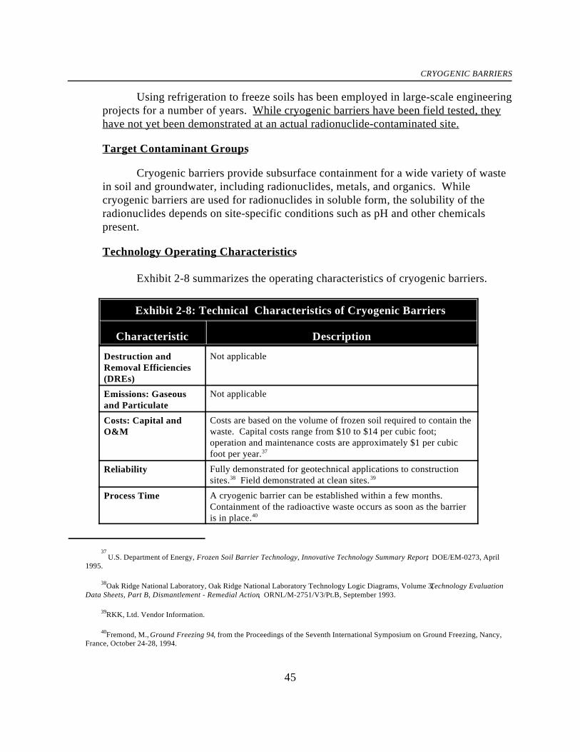
CRYOGENIC BARRIERS
37
U.S. Department of Energy, Frozen Soil Barrier Technology, Innovative Technology Summary Report, DOE/EM-0273, April1995.
Oak Ridge National Laboratory, Oak Ridge National Laboratory Technology Logic Diagrams, Volume 3, Technology Evaluation 38
Data Sheets, Part B, Dismantlement - Remedial Action, ORNL/M-2751/V3/Pt.B, September 1993.
RKK, Ltd. Vendor Information. 39
Fremond, M., Ground Freezing 94, from the Proceedings of the Seventh International Symposium on Ground Freezing, Nancy, 40
France, October 24-28, 1994.
45
Using refrigeration to freeze soils has been employed in large-scale engineeringprojects for a number of years. While cryogenic barriers have been field tested, theyhave not yet been demonstrated at an actual radionuclide-contaminated site.
Target Contaminant Groups
Cryogenic barriers provide subsurface containment for a wide variety of wastein soil and groundwater, including radionuclides, metals, and organics. Whilecryogenic barriers are used for radionuclides in soluble form, the solubility of theradionuclides depends on site-specific conditions such as pH and other chemicalspresent.
Technology Operating Characteristics
Exhibit 2-8 summarizes the operating characteristics of cryogenic barriers.
Exhibit 2-8: Technical Characteristics of Cryogenic Barriers
Characteristic Description
Destruction andRemoval Efficiencies(DREs)
Not applicable
Emissions: Gaseousand Particulate
Not applicable
Costs: Capital andO&M
Costs are based on the volume of frozen soil required to contain thewaste. Capital costs range from $10 to $14 per cubic foot;operation and maintenance costs are approximately $1 per cubicfoot per year.37
Reliability Fully demonstrated for geotechnical applications to constructionsites. Field demonstrated at clean sites.38 39
Process Time A cryogenic barrier can be established within a few months. Containment of the radioactive waste occurs as soon as the barrieris in place.40

CRYOGENIC BARRIERS
Oak Ridge National Laboratory, Oak Ridge National Laboratory Technology Logic Diagrams, Volume 2, Part B, Remedial 41
Action, ORNL/M-2751/V2/Pt.B, September 1993.
U.S. Environmental Protection Agency, Office of Research and Development, Superfund Innovative Technology Evaluation 42
Program: Technology Profiles, Seventh Edition, EPA/540/R-94/526, November 1994.
Cryocell, Responses to Commonly Asked Questions About Frozen Soil Barriers Containing Hazardous Waste. 43
Oak Ridge National Laboratory, Oak Ridge National Laboratory Technology Logic Diagrams, Volume 2, Part B, Remedial 44
Action, ORNL/M-2751/V2/Pt.B, September 1993.
46
Exhibit 2-8: Technical Characteristics of Cryogenic Barriers (Cont.)
Characteristic DescriptionApplicable Media Soil, sediment, leachates, bulk waste, and groundwater
Pretreatment/SiteRequirements
Power for the refrigeration plant to freeze the soil is required. 41
Soil moisture content of 14% to 18% is considered optimal.
Type and Quantity ofResiduals
Generates no waste stream or residues.42
Disposal Needs andOptions
Not applicable. The contaminated media remain on-site.
Post-treatmentConditions
All waste remains on site. Refrigeration plant remains on-site tomaintain frozen barrier.
Ability to MonitorEffectiveness
Target contaminants can be monitored using monitoring wellspositioned internally and externally to the barrier. A fiber opticstemperature sensor system can monitor barrier temperature. 43
Potential radioactive emissions from the contaminated area can bemonitored.
Site Considerations
Design criteria for cryogenic barriers is site-specific and depends on wastetype, topography, soil condition, thermal conductivity, and groundwater movement. Cryogenic barriers are adaptable to any geometry, however drilling technologies maypresent a constraint. Power for the refrigeration plant to freeze the soil is required;remote sites may require electrical power and utility installation. Heat from high-44
level radioactive waste can increase electrical power needs for maintaining frozenbarriers. In extremely dry soils, moisture must be supplemented with injection pipesplaced within the barrier. For applications in humid and high ambient temperature

CRYOGENIC BARRIERS
45
U.S. Department of Energy, Frozen Soil Barrier Technology, Innovative Technology Summary Report, DOE/EM-0273, April1995.
Cryocell, Responses to Commonly Asked Questions About Frozen Soil Barriers Containing Hazardous Waste. 46
47
regions, proper ground insulation and near surface refrigerant piping may be requiredto ensure that surface to 2-foot depths are adequately frozen. 45
2.3.2 NCP Criteria Evaluation
Protection of Human Health and the Environment
Cryogenic barriers protect human health and the environment by reducingvertical and lateral migration of radioactive contaminants. This technology reducesrisk exposure pathways as long as the pipes and refrigeration system remain intact. Because the radioactive waste remains in place, there is a potential risk to humanhealth and the environment from radioactive emissions, particularly for waste locatednear the ground surface. These potential emissions should be carefully monitored.
Compliance with ARARs
At DOE sites with low-level waste, cryogenic barriers must meet theperformance criteria outlined in DOE Order 5820.2A. Compliance with other ARARsmust be determined on a site-specific basis.
Long-Term Effectiveness
Cryogenic barriers do not eliminate the radiotoxicity of the contaminants, theysimply limit their vertical and lateral migration. Demonstration results indicate a non-detectable contaminant diffusion rate through a 15-m cryogenic barrier in thousands ofyears. However, the frozen barrier must be maintained without any penetrations in46
order to be effective in the long-term. Monitoring the performance of cryogenicbarriers with monitoring wells and fiber optics temperature sensory systems isnecessary to ensure the long-term effectiveness of this technology. Also, because theradioactive waste remains on site, continual monitoring around the contaminated areais required to detect potential radioactive emissions.
Reduction of Radiotoxicity, Mobility, or Volume
Although cryogenic barriers do not reduce the radiotoxicity or volume of thecontaminated material, they do reduce the horizontal and vertical mobility ofcontaminants in soil and groundwater.

CRYOGENIC BARRIERS
47
U.S. Department of Energy, Frozen Soil Barrier Technology, Innovative Technology Summary Report, DOE/EM-0273, April1995.
48
Short-Term Effectiveness
Health and safety issues are associated with drilling, prior to installation of therefrigerant piping. If drilling occurs in contaminated areas, site workers can beexposed to radiation from the drilling equipment. The cryogenic barrier effectivelycontains radioactive waste upon implementation and activation. However, because thewaste remains on-site, radioactive emissions may be produced from the contaminatedarea.
Implementability
Site conditions must be evaluated before implementing cryogenic barriers. Standard well drilling techniques are used to drill or drive the freeze pipes into place.This technology requires a power source, since a refrigeration plant is needed tomaintain the refrigerant. Necessary equipment, such as mobile refrigeration units,freeze fittings, insulated piping systems, and drilling equipment, is readily available. The establishment of a complete cryogenic barrier system can be implemented, usinglarge-scale temporary refrigeration equipment, in just a few months.
Cost
Costs are based on the volume of frozen soil required to effectively contain theradioactive waste. Total capital cost for the cryogenic barrier is estimated to rangebetween $10 to $14 per cubic foot. Using more expensive cryogenics (e.g., liquidnitrogen) in areas with low freezing points could increase capital costs. Average47
operation and maintenance costs are approximately $1 per cubic foot per year. Heatfrom high-level radioactive waste may increase electrical power needs andmaintenance costs.
2.3.3 Summary
A cryogenic barrier is a containment technology that prevents vertical andhorizontal migration of contaminants, including radionuclides. The technologyinvolves installing freeze pipes outside and beneath the contaminated zone to form anice barrier. Cryogenic barriers are effective upon implementation and provide long-term reduction in risk exposure pathways, as long as the pipes and refrigeration system

CRYOGENIC BARRIERS
49
remain intact. A monitoring system can be incorporated within and around thecryogenic barriers to ensure effectiveness.
Cryogenic barriers have been fully demonstrated for geotechnical applicationsto construction sites, and have been field demonstrated at clean sites. The waste type,topography, soil condition, thermal conductivity, and groundwater movement of aspecific site must be assessed prior to implementation. In order for cryogenic barriersto be effective, soil moisture must be adequate and a suitable power source must beavailable at the site. The technology’s advantages include in-situ application, whichreduces the potential exposure to radionuclides, and relatively easy barriermaintenance. Disadvantages of cryogenic barriers include the potential for radioactiveemissions from the contaminated area and the need for ongoing refrigeration tomaintain the barrier.
Exhibit 2-9 summarizes the data and analyses presented in this profile and canbe used for technology comparison.
Exhibit 2-9: NCP Criteria for Cryogenic Barriers
NCP Criterion Evaluation Performance Data
Overall Protectiveness `• Eliminates risks of • Useful for reducing migration ofmigration by containing of contaminants.waste.
• Potential radioactiveemissions from thecontaminated area,particularly if waste islocated near the groundsurface.
Compliance withARARs must comply with DOE Order
• Compliance with soil and • DOE sites with low-level wastegroundwater ARARs mustbe determined on a site-specific basis.
5820.2A.
Reduction ofRadiotoxicity,Mobility, or Volume
• Reduces mobility, but not • Process does not remove orradiotoxicity or volume, of reduce contaminants.contaminated media. • Reduces vertical and lateral
migration of contaminants.

CRYOGENIC BARRIERS
50
Exhibit 2-9: NCP Criteria for Cryogenic Barriers (Cont.)
NCP Criterion Evaluation Performance Data
Long-TermEffectiveness andPermanence
• Leaves untreated • Demonstration results show acontaminated media in nondetectable contaminantplace. diffusion rate through a 15-m
• Potential radioactiveemissions from thecontaminated area. • A monitoring system should be
• Long-term barriereffectiveness depends onproper maintenance.
cryogenic barrier in thousands ofyears.
incorporated to evaluate thebarrier’s effectiveness and todetect radioactive emissions.
Short-TermEffectiveness
• Effective in reducing • Requires large-scale temporarycontaminant migration refrigeration equipment foronce the barrier is in place. response in the short-term. Barriers can be fullyimplemented within 3months.
• Potential risk of exposureto site workers if drillingoccurs in contaminatedareas.
Implementability • Equipment and power is • No offsite activity is necessaryneeded to freeze the soil. to treat or store the waste.
• Site-specific • Depends on waste type,characterization is needed. topography, soil condition,
thermal conductivity, andgroundwater movement.
Cost • Costs are mainly • Capital costs are reported toassociated with electrical range from $10 to $14 per cubicpower needs and are foot. O&M costs aredependent on the size of approximately $1 per cubic footthe contaminated area and per year.the heat produced by thecontained waste.
• Heat from high-level radioactivewaste can increase O&M costs.

VERTICAL BARRIERS
U.S. Environmental Protection Agency, Office of Research and Development, Technological Approaches to the Cleanup of 48
Radiologically Contaminated Superfund Sites, EPA/540/2-88/002, August 1988.
Ibid. 49
50
Mauro, M. “Construction of Deep Barrier Walls for Waste Containment.” Environmental Restoration Conference , 1995.
51
2.4 VERTICAL BARRIERS
2.4.1 Technology Characterization
Description
A vertical barrier is a containment technology that is installed around acontaminated zone to help confine radioactive waste and any contaminatedgroundwater that might otherwise flow from the site. Vertical barriers also divertuncontaminated groundwater flow away from a site. Vertical barriers must reachdown to an impermeable natural horizontal barrier, such as a clay zone, in order toeffectively impede groundwater flow. This technology is often used when the wastemass is too large to practically treat and where soluble and mobile constituents pose animminent threat to a drinking water source. Vertical barriers are frequently used inconjunction with a surface cap to produce an essentially complete containmentstructure. Two types of vertical barriers used to contain radioactive waste are slurry48
walls and grout curtains.
Slurry walls are subsurface barriers that consist of a vertically excavated trenchfilled with a slurry. The slurry both hydraulically shores the trench to prevent thecollapse of the side walls during excavation and produces a barrier to groundwaterflow (see Exhibit 2-10). The slurry is generally a mix of bentonite and water orcement, bentonite, and water. When a strong vertical barrier is required, diaphragm49
walls are constructed with pre-cast or cast-in-place concrete panels. Composite slurrywalls, consisting of an impervious artificial barrier in a wall excavated with self-hardening slurry, are more resistant to chemical attacks and also reduce the barrier’shydraulic conductivity. Slurry walls are generally 0.6 to 1.2 meters (2 to 4 feet) thick50

VERTICAL BARRIERS
U.S. Department of Defense, Environmental Technology Transfer Committee, Remediation Technologies Screening Matrix and 51
Reference Guide, Second Edition, October 1994.
52
Mauro, M. “Construction of Deep Barrier Walls for Waste Containment.” Environmental Restoration Conference , 1995.
U.S. Environmental Protection Agency, Office of Research and Development, Technological Approaches to the Cleanup of 53
Radiologically Contaminated Superfund Sites, EPA/540/2-88/002, August 1988.
Oak Ridge National Laboratory, Oak Ridge National Laboratory Technology Logic Diagrams, Volume 3, Technology Evaluation 54
Data Sheets, Part B, Dismantlement - Remedial Action, ORNL/M-2751/V3/Pt.B, September 1993.
55
Heiser, J. “Demonstration of Close-Coupled Barriers for Sub-Surface Containment of Buried Waste” Environmental RestorationConference, 1995.
52
and are typically placed at depths less than 15 meters (50 ft), although slurry walls up51
to 200 feet in depth have been successfully constructed. 52
Grout curtains are narrow, vertical, grout walls installed in the ground. Theyare constructed by pressure-injecting grout directly into the soil at closely spacedintervals around the waste site. The spacing is selected so that each "pillar" of groutintersects the next, thus forming a continuous wall or curtain. Grout curtains may be53
used up-gradient of the contaminated area, to prevent clean water from migratingthrough waste, or down-gradient, to limit migration of contaminants. Grout curtainsare generally used at shallow depths (30 to 40 ft maximum depth). Typical grouting54
materials include hydraulic cements, clays, bentonite and silicates. However, thesematerials may crack or may not be durable or chemically compatible. Polymer groutsare used for barrier applications because they are impermeable to gases and liquids andresist radiation, as well as acidic and alkaline environments. A barrier that is currentlyundergoing field testing consists of a conventional cement grout curtain with a thinlining of polymer grout. Close-coupled barriers such as this can be used for a widerange of waste in addition to radionuclides, and in a variety geohydrologicconditions.55

Compacted Fill
Clay
Top Soil
Membrane
Soil Contaminated with Radioactive WasteClean
Soil
Confining Layer
Surface
Slu
rry
Wall
Slu
rry
Wall
VERTICAL BARRIERS
53
Exhibit 2-10: Vertical BarriersTarget Contaminant Groups
Vertical barriers provide subsurface containment for a wide variety of waste,including radionuclides, metals, and organics.
Technology Operating Characteristics
Exhibit 2-11 summarizes the operating characteristics of vertical barriers.
Exhibit 2-11: Technical Characteristics of Vertical Barriers
Characteristic Description
Destruction andRemoval Efficiencies(DREs)
Not applicable

VERTICAL BARRIERS
U.S. Department of Defense, Environmental Technology Transfer Committee, Remediation Technologies Screening Matrix and 56
Reference Guide, October 1994.
Oak Ridge National Laboratory, Oak Ridge National Laboratory Technology Logic Diagrams, Volume 3, Technology Evaluation 57
Data Sheets, Part B, Dismantlement - Remedial Action, ORNL/M-2751/V3/Pt.B, September 1993.
54
Exhibit 2-11: Technical Characteristics of Vertical Barriers (Cont.)
Characteristic DescriptionEmissions: Gaseousand Particulate
Not applicable
Costs: Capital andO&M
Most costs are capital; O&M costs involve monitoring andmitigation. Slurry walls range from $540 to $750 per square meter.
Grout curtains range from $30 to $40 per square foot.56 57
Reliability Reliable upon implementation, however vertical barriers oftendeteriorate over time.
Process Time Not applicable. The barrier is effective upon implementation.
Applicable Media Soil, sediment, leachates, bulk waste, and groundwater
Pretreatment/SiteRequirements
Detailed knowledge of soil characteristics and site geology.
Type and Quantity ofResiduals
Not applicable
Disposal Needs andOptions
Not applicable
Post-TreatmentConditions
Regulatory compliance procedures would apply (e.g. monitoringand mitigation).Institutional controls, such as deed, site access, and land userestrictions, are usually required.
Ability to MonitorEffectiveness
Can monitor the contamination level of nearby groundwater andthe integrity of the vertical barriers.
Site Considerations
Successful installation of a vertical barrier requires detailed knowledge of thesoil's physical and chemical characteristics and the subsurface geology. Manycommon chemical (particularly organic) contaminants that may be present atradioactive waste sites can destroy certain grout materials or prevent them fromsetting. Therefore, characterization of the site waste, leachate, and barrier materialchemistry, as well as compatibility testing of the barrier material with the likely

VERTICAL BARRIERS
58
Siskind, B. and Heiser, J. “Regulatory Issues and Assumptions Associated with Barriers in the Vadose Zone Surrounding BuriedWaste.” Brookhaven National Laboratory, 1993.
U.S. Environmental Protection Agency, Office of Research and Development, Technological Approaches to the Cleanup of 59
Radiologically Contaminated Superfund Sites, EPA/540/2-88/002, August 1988.
55
chemical environment, is required. Other site conditions that may also affect the58
integrity of the barrier include climate, which influences wet-dry cycling, and tectonicactivity.
2.4.2 NCP Criteria Evaluation
Protection of Human Health and the Environment
In general, vertical barriers protect human health and the environment byreducing exposure pathways due to the migration of contaminants. Their effectivenesslargely depends on the presence of a confining layer of clay or rock, into which thevertical barrier is keyed. Without a confining layer, the vertical barrier will not forman effective barrier because groundwater will flow under the barrier. Possibledeterioration of the barrier walls, caused by chemicals in the waste (e.g., organiccompounds) and wet-dry cycling in soils, could cause leaching of contaminatedgroundwater into the surrounding environment. 59
During trench excavation, if applicable, nearby populations and site workersare at risk of exposure to radioactive contaminants due to fugitive dust and gasemissions. To mitigate these hazards, fugitive dust control techniques and limitingoperations to favorable meteorological conditions should be practiced.
Compliance with ARARs
Compliance with ARARs must be determined on a site-specific basis. At DOEfacilities, vertical barriers must comply with performance criteria outlined in DOEOrder 5820.2A.
Long-Term Effectiveness
Vertical barriers have been used for decades as long-term solutions forcontrolling seepage of contaminated groundwater. However, vertical barriers donothing to eliminate the toxicity associated with radionuclides or any othercontaminants — they simply confine the contaminants to the site, thereby inhibitingcontaminant migration. Slurry walls and grout curtains both have the potential todegrade or deteriorate over time due to certain chemicals contained in the waste and

VERTICAL BARRIERS
60
MWLID Sandia/Westinghouse Hanford, “Verification of Sub-Surface Barriers using Time Domain Reflectometry (TDR) withWaveguides” 1994.
61
U.S. Environmental Protection Agency, Office of Research and Development, Technological Approaches to the Cleanup ofRadiologically Contaminated Superfund Sites, EPA/540/2-88/002, August 1988.
Ibid. 62
63
U.S. Department of Defense, Environmental Technology Transfer Committee, Remediation Technologies Screening Matrix andReference Guide, October 1994.
56
various weathering processes. In contaminated environments, their long-termeffectiveness is very dependent on contaminant types and concentrations. The long-term effectiveness of vertical barriers may be improved through use of such materialsas HDPE membranes and polymer grouts, which have increased chemical resistanceand reduced hydraulic conductivity.
Monitoring the barrier(s) and the surrounding groundwater is necessary toensure long-term effectiveness. Technologies that help monitor subsurface barriersinclude sensors placed within and adjacent to barriers to detect significant changes inmoisture content, and the use of gaseous tracers to locate breaches. 60
Reduction of Radiotoxicity, Mobility, or Volume
Vertical barriers do not reduce the radiotoxicity or volume of contaminatedmaterial, although they reduce the horizontal mobility of contaminants in soil orgroundwater plumes.
Short-Term Effectiveness
As soon as they are in place, vertical barriers can significantly reduce exposurerisks. However, it is difficult to obtain truly low permeabilities in grout curtains thatare constructed of nonconsolidated materials. Also, many chemical contaminants canprevent certain grout materials from setting. These factors may limit the61
effectiveness of grout curtains.
Implementability
Vertical barriers in soil and soil-like materials are relatively easy to install. 62
Because slurry walls have been used for decades, the equipment and methodology arereadily available and well-known. However, the process of designing the proper mixof wall materials to contain specific contaminants is less well developed. Excavationand backfilling of the slurry trench is critical and requires experienced contractors.63

VERTICAL BARRIERS
57

VERTICAL BARRIERS
64
Oak Ridge National Laboratory, Oak Ridge National Laboratory Technology Logic Diagrams, Volume 3, Technology EvaluationData Sheets, Part B, Dismantlement - Remedial Action, ORNL/M-2751/V3/Pt.B, September 1993.
58
Cost
Vertical barrier costs are mostly capital costs; operation and maintenance costsinclude monitoring and mitigation. Estimated costs for the design and installation of astandard slurry wall in soft to medium soil range from $540 to $750 per square meter. The use of an HDPE membrane in a slurry wall will increase the capital cost. Groutcurtains with conventional materials generally cost between $30 to $40 per squarefoot. Use of a close-coupled barrier with a polymer grout lining increases the capitalcost. These costs do not include variable costs required for chemical and radiological
analyses, feasibility, or compatibility testing. Testing costs depend heavily on site-specific factors. Other site-specific factors that significantly impact the final cost ofslurry wall or grout curtain installation include:
• type, activity, and distribution of contaminants;• depth, length, and width of the wall;• geological and hydrological characteristics;• distance from the source of materials and equipment;• requirements for wall protection and maintenance.64
2.4.3 Summary
A vertical barrier is a containment technology used to help confine radioactivewaste and any contaminated groundwater that might otherwise flow from the site. Two types of vertical barriers used to contain radioactive waste are slurry walls andgrout curtains. Both are often used in conjunction with capping to provide morethorough waste containment. Vertical barriers are effective upon implementation. Costs of this technology depend on the barrier materials selected and site-specificconditions. Although installing vertical barriers requires expertise, the process is notcomplex and materials are readily available.
The following factors may limit the applicability and effectiveness of usingvertical barriers:
• vertical barriers must reach down to an impermeable horizontal barrierto effectively impede groundwater flow;
• thorough characterization of the subsurface is required because settlingor unstable ground can limit effectiveness;

VERTICAL BARRIERS
U.S. Environmental Protection Agency, Office of Research and Development, Technological Approaches to the Cleanup of 65
Radiologically Contaminated Superfund Sites, EPA/540/2-88/002, August 1988.
59
• conventional barrier materials do not withstand attack by strong acids,bases, salt solutions, and some organic chemicals;
• vertical barriers can degrade or deteriorate over time.
Exhibit 2-12 summarizes the data and analyses presented in this profile and canbe used for technology comparison.
Exhibit 2-12: NCP Criteria for Vertical Barriers
NCP Criterion Evaluation Performance Data
Overall Protectiveness • Eliminates many risks due to • Successfully diverts uncontaminatedmigration by containing the groundwater flow.waste. • Useful for reducing contaminant
migration.
Compliance withARARs
• Compliance with soil and • DOE sites must comply withgroundwater ARARs must performance criteria in Orderbe determined on a site- 5820.2A.specific basis.
Reduction ofRadiotoxicity,Mobility, or Volume
• Reduces mobility, but not • Process does not remove or reduceradiotoxicity or volume, of contaminants.contaminated media. • Reduces lateral migration of
contaminants.
Long-TermEffectiveness andPermanence
• Leaves untreated • Depends on contaminant types andcontaminated media in place. concentrations.
• Potentially ineffective in the • Possibility of barrier deteriorationlong-term due to potential over the long-term. Possible sitebarrier deterioration. conditions that could affect barrier
integrity include climate and tectonicactivity.
Short-TermEffectiveness
• Potential risks to site • The effectiveness of grout curtainsworkers if extensive may be reduced if constructed of non-excavation is required. consolidated materials or in the
presence of certain chemicals.65

VERTICAL BARRIERS
60
Exhibit 2-12: NCP Criteria for Vertical Barriers (Cont.)
NCP Criterion Evaluation Performance Data
Implementability • Relatively easy to • Excavation and backfilling slurryimplement. trench requires experienced
• Equipment and methodologyare well-known and readily • Thorough characterization of wasteavailable. type, topography, soil condition,
contractors.
thermal conductivity, andgroundwater movement is important.
Cost • Most costs are capital; O&M • Slurry walls: $540 to $750 per squarecosts include monitoring and meter.mitigation.
• Capital cost is dependent on foot.the type of barriers materialsselected.
• Grout curtains: $30 to $40 per square
• HDPE membranes or polymer groutsincreases cost.

SOLIDIFICATION/STABILIZATION
Solidification/Stabilization technologies reduce the mobility of hazardous andradioactive contaminants in the environment through both physical and chemical processes. Stabilization seeks to trap contaminants within their "host" medium (i.e., the soil, sand, and/orbuilding materials that contain them), by inducing chemical reactions between the stabilizingagent and contaminants, thus reducing their mobility. Solidification encapsulates the waste ina monolithic solid of high-structural integrity. Solidification does not involve chemicalinteraction between the contaminants and the solidification agents but are bondedmechanically. Solidification and stabilization techniques are often used together. The intentof solidification and/or stabilization processes would be to limit the spread of radioactivematerial and to trap and contain radon within the monolithic solid. While the contaminantswould not be removed and would remain radioactive, the mobility of the contaminants wouldbe eliminated or reduced.
Solidification/Stabilization has been implemented full-scale and may be employed in-situ or ex-situ. In-situ techniques use auger/caisson systems and injector head systems toapply agents to in-situ soils. Ex-situ techniques differ from in-situ techniques because ex-situprocesses involve digging up the materials and machine-mixing them with the solidifyingagent instead of injecting the agent to the materials in place. Ex-situ processes typicallyrequire disposal of the resultant materials. In-situ and ex-situ techniques can be used alone orcombined with other treatment and disposal methods to yield a product or material suitablefor land disposal or, in other cases, that can be applied to beneficial use. Both techniqueshave been used as final and interim remedial measures.
This profile presents:
• Cement solidification/stabilization (S/S)• Chemical solidification/stabilization (S/S)
There may be one or more sub-options applicable to each process.
The flow diagrams in Exhibit 2-13 and Exhibit 2-14 illustrate the general processinvolved with ex-situ and in-situ Solidification/Stabilization technologies respectively.

Soil Contaminated with Radioactive
Waste
Dry Reagent
Silo
Hopper with Even Feeder
Weight Feeder
Homogenizer
Auger
Solidified Product Containing Radioactive Materials
Liquid Reagent Storage
Pug Mill Dry Reagent Feeder
Stabilized/Solidified Media
ResidualsMixingOff-Gas
Treatment (optional)Solidification/Stabilization
Binding Agent(s)
Water
SOLIDIFICATION/STABILIZATION
62
Exhibit 2-13: Ex-Situ Solidification/Stabilization

CEMENT SOLIDIFICATION/STABILIZATION
63
2.5 CEMENTSOLIDIFCATION/STABILIZATION
Exhibit 2-14: In-Situ Solidification/Stabilization
2.5.1 Technology Characterization
Description
Cement solidification/stabilization (S/S) processes involve the addition ofcement or a cement-based mixture which limits the solubility or mobility of the wasteconstituents. These techniques are accomplished in-situ by either injecting a cement-based agent into the contaminated materials, or ex-situ by excavating the materials,machine-mixing them with a cement-based agent, and depositing the solidified mass ina designated area. The goal of the S/S process is to limit the spread of radioactivematerial via leaching, and to trap and contain radon within a densified soil mass. Thisprocess does not remove or inactivate contaminants, but eliminates or reducescontaminant mobility.
The end product resulting from the solidification process is a monolithic blockof waste with high structural integrity. Types of solidifying/stabilizing agents includethe following: Portland; gypsum; modified sulfur cement, consisting of elementalsulfur and hydrocarbon polymers; and grout, consisting of cement and other drymaterials, such as acceptable fly ash or blast furnace slag. Processes utilizingmodified sulfur cement are typically performed ex-situ.
Target Contaminant Groups
Properly implemented, cement S/S can apply to most contaminants, includingall classes of radioactive waste, organics, inorganics, heavy metals, and mixed waste. This technology, however, may have limited effectiveness against SVOCs andpesticides. In general, in-situ cement S/S can be considered at any site from whichradioactive waste cannot be removed. Type I Portland cement-based grout iscommonly used to solidify most hazardous waste, while Types II and V Portlandcement-based grouts are used for waste containing sulfates or sulfites.
Technology Operating Characteristics
Cement S/S could be considered for a variety of situations but is best suited tohighly porous, coarse-grained, low-level radioactive waste in permeable matrices.

CEMENT SOLIDIFICATION/STABILIZATION
66
U.S. Environmental Protection Agency, Solid Waste and Emergency Response, Innovative Site Remediation Technology,Solidification/Stabilization, Volume 4, EPA 542-B-94-001, June 1994.
U.S. Department of Defense, Environmental Technology Transfer Committee, Remediation Technologies Screening Matrix and 67
Reference Guide, Second Edition, October 1994.
. 68
Ibid.
64
Exhibit 2-15 summarizes the operating characteristics of cementsolidification/stabilization.
Exhibit 2-15: Technical Characteristics of CementSolidification/Stabilization (S/S)
Characteristic Description
Destruction andRemoval Efficiencies(DREs)
Not applicable
Emissions: Gaseousand Particulate
If necessary, a hood can be placed over the system to capturevolatile contaminants released during the injection process.
UnconfinedCompressive Strength
Strengths for modified sulfur cement twice those of Portlandcements have been achieved. Strengths for sulfur cement are inthe range of 27.6 MPA (4000 psi).66
Costs: Capital and For ex-situ solidification/stabilization processes, overall costs fromO&M more than a dozen vendors are under $100 per ton, including
excavation. The in-situ soil mixing/auger techniques average $40- $60 per cubic yard for shallow applications and $150 - $250 percubic yard for deeper applications. 67
Reliability The long-term effects of weathering, groundwater infiltration, andphysical disturbance cannot be predicted accurately.
Process Time The shallow in-situ soil mixing technique for in-situ applicationsprocesses 40 - 80 tons per hour on average, and the deep soilmixing technique averages 20 - 50 tons per hour. 68
Applicable Media Soils, sediments, sludges, refuse

CEMENT SOLIDIFICATION/STABILIZATION
U.S. Environmental Protection Agency, Office of Research and Development, Approaches for the Remediation of Federal Facility 69
Sites Contaminated with Explosive or Radioactive Waste, EPA/625/R-93/013, September 1993.
U.S. Environmental Protection Agency, Solid Waste and Emergency Response, Innovative Site Remediation Technology, 70
Solidification/Stabilization, Volume 4, EPA 542-B-94-001, June 1994.
U.S. Environmental Protection Agency, Office of Emergency and Remedial Response, Summary of Treatment Technology 71
Effectiveness for Contaminated Soil, PB92-963351, June 1990.
65
Exhibit 2-15: Technical Characteristics of CementSolidification/Stabilization (S/S) (Cont.)
Characteristic DescriptionPre-Treatment/Site Before in-situ cement solidification/stabilization is applied at anyRequirements site, extensive laboratory studies should be conducted to
incorporate performance criteria, process criteria, and site-specificcriteria. Laboratory studies also can address design issues such as69
achieving a specific permeability, minimizing volume increase, oreliminating surface berms.Prior to modified sulfur cement S/S, the waste should be dried. 70
Type and Quantity ofResiduals
Radioactive materials are left in place. No residuals are produced.
Disposal Needs andOptions in-situ approach. Excavated and mixed mass can be contained or
The solidified/stabilized mass remains in place when utilizing the
buried on or off site.
Post-Treatment With the in-situ approach or on site burial, all waste will remain atConditions the site. Institutional and engineering controls will most likely be
required. Ex-situ solidification may facilitate the transportation ofoff site disposal of radioactive contaminants with the use ofcontainers, especially where volume reduction or extractiontechniques have been applied, previously.
Ability to MonitorEffectiveness
The level of performance for stabilization process is measured bythe amount of constituents that can be leached from the stabilizedmaterial. Two techniques recognized by USEPA as measure ofleachability are the Extraction Process (EP) Toxicity Test and theToxicity Characteristic Leaching Procedure (TCLP). 71

CEMENT SOLIDIFICATION/STABILIZATION
72
U.S. Environmental Protection Agency, Office of Emergency and Remedial Response, Solification/Stabilization of Organics andInorganics, EPA/540/S-92/015, May 1993.
66
Site Considerations
The in-situ method also may not be suitable if masses are thin, discontinuous,and at or near the surface. Special concerns may be posed by other types of hazardouswaste (e.g., organic chemicals) that may interfere with solidifying the radioactivewaste. Some factors include inorganic acids that will decrease durability for PortlandType I cement; chlorinated organics that may increase set time and decrease durabilityof cement if concentration is too high; and oil and grease that will decrease unconfinedcompressive strength.72
In-situ S/S may not be suitable for some sites because gamma radiation mightnot be reduced sufficiently, and because maintenance of utilities would be difficult. Consideration must also be given to any debris such as barrels, scrap metals, and woodpieces that may interfere with the solidification process. Environmental risks relatedto drilling through the buried waste exist, especially if liquid-filled drums are piercedand their contents are spilled. The fluid inside the containers may contain materialdetrimental to the cementation process. If whole drums can be located, removalshould be considered to eliminate risk of puncture.
Several soil characteristics influence whether the technology will contain thewaste effectively. These characteristics include void volume, which determines howmuch grout can be injected into the site; soil pore size, determines the size of thecement particles that can be injected; and permeability of the surrounding, whichdetermines whether water will flow preferentially around the solidified mass.
2.5.2 NCP Criteria Evaluation
Protection of Human Health and the Environment
Although this technology does not reduce the toxicity or volume ofcontaminants, if successful, it has been proven to greatly reduce the mobility, thusprotecting human health and the environment by reducing risk of exposure. However,process control is relatively poor and it is difficult to verify that the monolith actuallycontains the waste. Since cement solidification may not shield or eliminate radiationeffects, some form of capping or shielding may be appropriate.

CEMENT SOLIDIFICATION/STABILIZATION
PNL-SA-21482 October 1992. 73
U.S. Department of Defense, Environmental Technology Transfer Committee, Remediation Technologies Screening Matrix and 74
Reference Guide, Second Edition, October 1994.
Ibid. 75
67
Compliance with ARARs
The treatment must result in residual soil levels that comply with NRCrequirements and RCRA LDRs. Since no material is actually removed from the siteduring in-situ solidification, the site must be appropriate for leaving the material onsite in a less mobile form. Compliance with other ARARs need to be determined on asite-specific basis.
Long-Term Effectiveness
Leach resistance of some solidified/stabilized waste is relatively high. 73
However, the long-term effects of weathering, groundwater infiltration, and physicaldisturbance associated with uncontrolled future land use can significantly affect theintegrity of the stabilized mass and contaminant mobility in ways that cannot bepredicted.74
Reduction of Radiotoxicity, Mobility, or Volume
While solidification and stabilization reduce the mobility of a contaminant, thevolume of the waste increases, and there is only an incidental effect on toxicity. In-situ processes have demonstrated the capability to reduce the mobility of contaminatedwaste by greater than 95 percent.75
Short-Term Effectiveness
In-situ processes result in risk of exposure since injection is performedvertically over the waste. During ex-situ processes there are potential risks ofexposure to workers during the excavation, mixing, and handling of waste. Also,fugitive dust emissions resulting from excavation could potentially expose workersand the surrounding community.

CEMENT SOLIDIFICATION/STABILIZATION
Ibid. 76
68
Implementability
Cement S/S is well demonstrated and easy to implement. Most reagents andadditives are generally widely available and relatively inexpensive industrialcommodities. However, detailed characterization of the site and the waste matrix isrequired to determine the suitability of in-situ processes.
Cost
Costs can vary based on specific soil conditions, contaminants, and availabilityof solidification agents. Also, ex-situ costs for transportation and offsite disposal ofthe solidified material play a role in the overall cost. Low costs may reflect in-situmixing techniques and high costs may reflect in-drum mixing techniques.
2.5.3 Summary
The following factors may limit the applicability and effectiveness of cement S/S:
In-situ Techniques
• Depth of contaminants may limit some types of application processes.• Future usage of the site may "weather" the materials and affect ability to
maintain immobilization of contaminants.• Some processes result in significant increase in volume (up to double
the original volume).• Certain waste are incompatible with variations of this process.
Treatability studies are generally required. Reagent delivery andeffective mixing are more difficult than for ex-situ applications.
• Like all in-situ treatments, confirmatory sampling can be more difficultthan for ex-situ treatments.76
Ex-situ Techniques
• Environmental conditions may affect the long-term immobilization ofcontaminants.
• Some processes result in a significant increase in volume (up to doublethe original volume).

CEMENT SOLIDIFICATION/STABILIZATION
Ibid. 77
69
• Certain waste are incompatible with different processes. Treatabilitystudies are generally required.
• VOCs are generally not immobilized.• Long-term effectiveness has not been demonstrated for many
contaminant/process combinations.77
Solidification/stabilization technologies are well demonstrated, can be applied to themost common site and waste types, require conventional materials handling equipment, andare available competitively from a number of vendors.
Exhibit 2-16 summarizes the data and analyses presented in this profile and can beused for technology comparison.
Exhibit 2-16: NCP Criteria for Cement Solidification/Stabilization (S/S)
NCP Criterion Evaluation Performance Data
Overall Protectiveness • Limited overall • May not shield or eliminate radiationprotectiveness at site; effects.however, does preventmigration ofcontaminants toexposure pathways.
Compliance withARARs
• Determined on a site- • Determined on a site-specific basis.specific basis.
Reduction of • In-situ processes do not involve removal orRadiotoxicity, Mobility, destruction of contaminants, however,or Volume solidification may be able to reduce the
• Does not reduce toxicityor volume; does reducemobility.
release of radon and associatedradioactivity to acceptable levels at thewaste site without removal of materials foroff site containment.
Long-TermEffectiveness andPermanence
• Technology is not • Cement S/S is acceptable for reducing theproven in the long-term. leachability of radionuclides or heavy
metals. However, the long-term effects ofweathering, groundwater infiltration, andphysical disturbance cannot be predicted.

CEMENT SOLIDIFICATION/STABILIZATION
70
Exhibit 2-16: NCP Criteria for Cement Solidification/Stabilization (S/S) (Cont.)
NCP Criterion Evaluation Performance Data
Short-TermEffectiveness and handling of waste during ex-situ
• Risk exists to both • Fugitive dust generation from excavationworkers and/or thenearby communityduring solidificationprocesses.
processes poses a health and safety risk toworkers and nearby communities. Risk toworkers also results from drilling duringin-situ techniques.
Implementability • Easy to implement. • Based onsite circumstances, technologymay have to be combined with othertreatment methods (e.g., use of soil coveror cap). Sufficient mixing must occurbetween soil and grouting materials to beeffective.
Cost • Relatively low cost • Documented costs range from $40 - $250technology. per cubic yard. Availability of
solidification agent selected and, for ex-situprocesses, transportation and disposal costswill affect the overall cost.

CHEMICAL SOLIDIFICATION/STABILIZATION
71
2.6 CHEMICALSOLIDIFCATION/STABILIZATION
2.6.1 Technology Characterization
Description
Chemical Solidification/Stabilization (S/S) involves adding chemical reagentsto waste in order to limit the waste solubility and mobility. It is accomplished eitherin-situ, by injecting a solidifying/stabilizing agent into contaminated materials, or ex-situ, by excavating and machine-mixing the materials with the solidifying/stabilizingagent and then placing the solidified soil in containers or burying it on site. Onsiteburial of the solidified soil requires a soil cover sufficiently thick to absorb gammaradiation. Chemical S/S agents include thermoplastic polymers (asphalt bitumen,paraffin, polyethylene), thermosetting polymers (vinyl ester monomers, ureaformaldehyde, epoxy polymers), and other proprietary additives. Chemical grouts canalso be used as S/S agents, however little information is available on this process.
The chemical S/S process limits the spread of radioactive material via leaching,and traps and contains radon within a dense soil mass. Rather than inactivatecontaminants, this process eliminates or reduces the contaminants’ mobility.
Target Contaminant Groups
Properly implemented, chemical S/S can apply to many contaminants,including all classes of radioactive waste, organics, inorganics, heavy metals, andmixed waste. This process may not be effective on other organics (e.g., SVOCs andpesticides) that can inhibit the chemical bonding of stabilizers or the mechanicalbonding of solidifying agents.
Technology Operating Characteristics
Exhibit 2-17 summarizes the operating characteristics of chemicalsolidification/stabilization.

CHEMICAL SOLIDIFICATION/STABILIZATION
U.S. Environmental Protection Agency, EPA/540/M5/89/001, 1989. 78
Ibid. 79
Ibid. 80
U.S. Department of Defense, Environmental Technology Transfer Committee, Remediation Technologies Screening Matrix and 81
Reference Guide, Second Edition, October 1994.
72
Exhibit 2-17: Technical Characteristics of ChemicalSolidification/Stabilization
Characteristic Description
Destruction and RemovalEfficiencies (DREs)
Not applicable
TCLP Results Poor for organic waste constituents. Excellent for metals.
Unconfined CompressiveStrength
220 to 1570 psi 78
390 to 860 psi 79
Emissions: Gaseous andParticulate
Volatile compounds can be released if mechanical mixing isinvolved.80
Costs: Capital and O&M For ex-situ processes, overall costs are under $100 per ton,including excavation. The in-situ soil mixing/auger techniquesaverage $40 - $60 per cubic yard for shallow applications and $150- $250 per cubic yard for deeper applications. Most reagents andadditives are also widely available, relatively inexpensive industrialcommodities.81
Reliability The reliability of most chemical stabilizing agents has yet to befully determined. Some testing has been performed on polyethylenewaste.

CHEMICAL SOLIDIFICATION/STABILIZATION
82
U. S. Environmental Protection Agency, Office of Research and Development, Approaches for the Remediation of FederalFacility Sites Contaminated with Explosive or Radioactive Waste, EPA/625/R-93/013, September 1993.
U.S. Department of Defense, Environmental Technology Transfer Committee, Remediation Technologies Screening Matrix and 83
Reference Guide, Second Edition, October 1994.
73
Exhibit 2-17: Technical Characteristics of ChemicalSolidification/Stabilization (Cont.)
Characteristic DescriptionProcess Time A typical full-scale polyethylene extruder can process 900
kilograms of mixed material per hour consisting of 30% binder and70% waste. The extruded material takes only a few hours to cooland to set.82
The shallow soil mixing technique for in-situ applications processes40 to 80 tons per hour on average; the deep soil mixing techniqueaverages 20 to 50 tons per hour. 83
Applicable Media Soils, sediments, sludges, refuse
Pretreatment/SiteRequirements
No pretreatment is required. However, testing must be performedto assess the effectiveness of the chemical mix with thecontaminant.
Disposal Needs and Solidified/stabilized mass remains in place with in-situ approach. Options Excavated and mixed mass must be contained or buried on- or off-
site.
Post-Treatment Conditions With the in-situ approach or on-site burial, all waste will remain atthe site. Institutional controls will probably be required.
Ability to MonitorEffectiveness
Rigorous verification involves digging up the perimeter of thestabilized/solidified area. Additionally, S/S does not lend itself towaste retrieval.
Site Considerations
While chemical S/S can be used in a variety of situations, it is better suited tofine-grained soil with small pores. The in-situ method may not be suitable forresidential sites because gamma radiation may not be sufficiently reduced, andbecause maintenance of utilities would be difficult. The in-situ method also may notbe suitable if masses are thin, discontinuous, and at or near the surface. Specialconcerns can be encountered by the presence of other types of hazardous waste that

CHEMICAL SOLIDIFICATION/STABILIZATION
Ibid. 84
74
may interfere with the solidification process -- organic chemicals could be particularlytroublesome.
2.6.2 NCP Criteria Evaluation
Protection of Human Health and the Environment
This technology provides protectiveness by greatly reducing the mobility ofradioactive materials. The solidified mass, under proper conditions, will remain intactfor long periods of time, although it may not shield or eliminate radiation effects. Some form of capping or shielding may therefore be appropriate.
Compliance with ARARs
During in-situ chemical S/S, no material is actually removed from the site. Thesite must be appropriate for leaving the material on site in a less mobile form. Thistechnology generally meets RCRA LDR requirements for metals, however organics inthe waste may inhibit cementation and chemical bonding processes and result in non-compliance.
Long-Term Effectiveness
Radioactive materials will remain onsite or wherever the solidified mass isdisposed of. The S/S process itself may not provide adequate shielding from all typesof radiation; covering or capping may be required. S/S should greatly reduce oreliminate the threat of groundwater contamination or other migration, although long-term site maintenance and institutional controls would be required. The long-termeffects of weathering, groundwater infiltration, and physical disturbance associatedwith uncontrolled future land use can significantly and unpredictably affect theintegrity of the stabilized mass. 84
Research is underway on the viability and reliability of most chemicalstabilizing agents. Water immersion and temperature fluctuation tests on polyethylenewaste forms showed no significant changes in compressive strength. In addition,exposure tests of radiation up to 10 rad increased cross-linking in the waste forms,8

CHEMICAL SOLIDIFICATION/STABILIZATION
85
U.S. Environmental Protection Agency, Office of Research and Development, Approaches for the Remediation of Federal FacilitySites Contaminated with Explosive or Radioactive Waste, EPA/625/R-93/013, September 1993.
75
thus were stronger, more stable under thermal cycling, more resistant to solvents, andmore resistant to leaching.85
Reduction of Radiotoxicity, Mobility, or Volume
While S/S reduces contaminant mobility, the volume of the waste increases;there is only an incidental effect on toxicity.
Short-Term Effectiveness
Potential risks of exposure to workers exist during waste handling. Also,fugitive dust emissions resulting from excavation could expose workers and thesurrounding community to contaminants. Transportation of waste to offsite disposalfacility for ex-situ treatment also increases exposure risks to workers and community.
Implementability
This process is generally easy to implement (e.g., uses conventional materialsand widely available equipment).
Cost
Costs vary. In-situ chemical processes usually cost less than ex-situ processes. Nonetheless, the range of costs is relatively low compared to other technologies.
2.6.3 Summary
Although chemical S/S may effectively reduce the mobility of radioactivecontaminants, it may not affect volume or toxicity. It is applicable to the mostcommon site and waste types, uses conventional materials handling equipment, and iswidely available. This technology usually requires capping or covering, engineeringcontrols, and/or institutional controls.
Factors that may limit the applicability and effectiveness of in-situ and ex-situS/S include:
In-situ techniques
• depth of contaminants may limit some types of application;

CHEMICAL SOLIDIFICATION/STABILIZATION
U.S. Department of Defense, Environmental Technology Transfer Committee, Remediation Technologies Screening Matrix and 86
Reference Guide, Second Edition, October 1994.
Ibid. 87
Ibid. 88
76
• future site use may "weather" the materials and affect their ability toimmobilize contaminants;
• some processes result in a significant volume increase (up to double theoriginal);
• certain waste are incompatible with process variations — treatabilitystudies are generally required; reagent delivery and effective mixing aremore difficult than for ex-situ applications;
• confirmatory sampling can be more difficult than for ex-situtreatments.86
Ex-situ techniques
• environmental conditions may affect long-term contaminant immobility;• some processes result in a significant volume increase (up to double the
original);• certain waste are incompatible with different processes treatability
studies are generally required;• VOCs are generally not immobilized;• long-term effectiveness has not been demonstrated for many
contaminant/process reagent combinations.87
Additionally, a major factor driving the selection process beyond basic wastecompatibility is the availability of suitable reagents. Chemical S/S processes requirethat potentially large volumes of bulk reagents and additives be transported to projectsites. Transportation costs may therefore dominate project budgets and may quicklybecome uneconomical in cases where materials are not locally available. 88
Exhibit 2-18 summarizes the data and analyses presented in this profile and canbe used for technology comparison.

CHEMICAL SOLIDIFICATION/STABILIZATION
77
Exhibit 2-18: NCP Criteria for Chemical Solidification/Stabilization
NCP Criterion Evaluation Performance Data
OverallProtectiveness
• Limited overall • May not shield or eliminateprotectiveness at site; radiation effects.however, does prevent • Effective in reducingmigration of contaminants leachability of radioactiveto exposure pathways. material. Some organic
constituents of mixed wastecan reduce effectiveness.
Exhibit 2-18: NCP Criteria for Chemical Solidification/Stabilization(Cont.)
NCP Criterion Evaluation Performance Data
Compliance withARARs
• Determined on a site- • Determined on a site-specific basis. specific basis.
Reduction ofRadiotoxicity,Mobility, or Volume
• Does not reduce toxicity or • Does not remove or destroyvolume of contaminants; contaminants.reduces mobility.
• Process can increasevolume of media aftersolidification.
Long-TermEffectiveness andPermanence
• Radioactive materials • Long-term site maintenanceremain on site or wherever of the site and institutionalthe solidified mass is controls may be required.disposed of. • Process can greatly reduce
• Process itself does not the threat of groundwaterprovide adequate shielding contaminants.from all types of radiation. • TCLP results are excellent
• Process leads to effective for metal and radionuclides;long-term reduction in poor for organics.exposure risks viagroundwater.

CHEMICAL SOLIDIFICATION/STABILIZATION
Exhibit 2-18: NCP Criteria for Chemical Solidification/Stabilization(Cont.)
NCP Criterion Evaluation Performance Data
78
Short-TermEffectiveness
• Excavation of waste can • Volatile contaminants canexpose site personnel. be released during mixing.
• Process can be completed • 1800 pounds per hour forwithin short timeframe. polyethylene process; only
• Transportation for off-site a few hours for cooling anddisposal can increase risk to setting of mass.community. • Ex-situ process may require
offsite disposal of solidifiedmass.
Implementability • Easy to implement. • Requires soil cover or cap• Many chemical stabilizing of sufficient thickness.
agents need further testing • Optimal conditions forand development. many chemical agents not
determined.
Cost • Costs depend on the • Costs range from $40 toavailability and/or $250 per ton.transportation of thesolidifying agents.

CHEMICAL SEPARATION
79
CHEMICAL SEPARATIONTECHNOLOGIES
Chemical separation involving the use of solvent/chemical extraction separates andconcentrates radioactive contaminants from soil. The process residuals require furthertreatment, storage, or disposal. Radionuclide contaminants can be extracted by usinginorganic salts, mineral acids, complexing agents, or organic solvents. There are notabledifferences in the extractability rates of each agent due to the types and concentrations ofcontaminants as well as varying conditions within the method. The implementability of thistechnology is controlled by site-specific factors and their applicability must be determined ona site by site basis.


SOLVENT/CHEMICAL EXTRACTIONSOLVENT/CHEMICAL EXTRACTION
Ibid. 89
U.S. Environmental Protection Agency, Office of Research and Development, Technological Approaches to the Cleanup of 90
Radiologically Contaminated Superfund Sites, EPA/540/2-88/002, August 1988.
U.S. Department of Energy, Office of Technology Development, Effective Separation and Processing Integrated Program (ESP- 91
IP), DOE, EM-0126P, 1994.
81
2.7 SOLVENT/CHEMICALEXTRACTION
2.7.1 Technology Characterization
Description
Solvent/chemical extraction is an ex-situ chemical separation technology thatseparates hazardous contaminants from soils, sludges, and sediments to reduce thevolume of hazardous waste that must be treated. Solvent/chemical extraction involvesexcavating and transferring soil to equipment that mixes the soil with a solvent. Thisequipment may handle contaminated soil either in batches, for dry soil, or as acontinuous flow, for pumpable waste. When the hazardous contaminants have beensufficiently extracted, the solvent is separated from the soil and distilled in anevaporator or column. Distilled vapor consists of relatively pure solvent that isrecycled into the extraction process; the liquid residue, which contains concentratedcontaminants, undergoes further treatment or disposal (see Exhibit 2-19). While notall radionuclides and solvent will be removed from the contaminated soil, if it issufficiently clean it can be returned to its original location. Otherwise, it may requireseparate storage or disposal.
Solvent/chemical extraction has been used extensively to extract uranium frommineral ores. However, using this technology to treat soils contaminated withradionuclides or mixed waste requires further development. Solvents that could be89
used to remove radioactive waste include: complexing agents, such as EDTA(ethylenediamine-tetraacetic acid); inorganic salts; organic solvents; and mineral acids,such as sulfuric, hydrochloric, or nitric acid. Each solvent’s effectiveness in removingdifferent contaminants depends on concentrations, pH, and solubility.90,91
While it can sometimes be used as a stand-alone technology, solvent/chemicalextraction is commonly used with other technologies, such as

Soil Contaminated with Radioactive
Waste
Waste Preparation
Extractor Separator
Emissions Control Treated Emissions
Radioactive Liquid Waste
Clean Soil WaterOversized
Rejects
Recycled
Solvent with
Organic Contaminants
SOLVENT/CHEMICAL EXTRACTION
Oak Ridge National Laboratory, Technology Evaluation Data Sheets, Part B, Dismantlement - Remedial Action, ORNL/M- 92
2751/V3/Pt.B, September 1993.
93
U.S. Environmental Protection Agency, Background Information Document for Radiation Site Cleanup Proposed Rule, RevisedDraft, August 1995.
82
solidification/stabilization, incineration, or soil washing, depending on site-specificconditions.
Exhibit 2-19: Solvent Extraction
Target Contaminant Groups
Depending on the solvents used, solvent/chemical extraction may potentiallyextract various radionuclides or mixed waste from contaminated media, using either abatch or continuous flow system. Laboratory experiments with uranium mill tailings92
indicate that inorganic salt extraction of radium and thorium is feasible, while mineralacids have been used to extract radium, thorium, and uranium from mineral ores. Complexing agents have also successfully removed radioisotopes of cobalt, iron,chromium, uranium, and plutonium from nuclear process equipment. Laboratoryexperiments suggest EDTA may be useful in extracting radium from soils andtailings.93

SOLVENT/CHEMICAL EXTRACTION
U.S. Environmental Protection Agency, Office of Research and Development, Technological Approaches to the Cleanup of 94
Radiologically Contaminated Superfund Sites, EPA/540/2-88/002, August 1988.
U.S. Environmental Protection Agency, Emerging Technology Summary: Acid Extraction Treatment System for Treatment of 95
Metal Contaminated Soils, EPA/540/SR-94/513, August 1994.
Oak Ridge National Laboratory, Technology Evaluation Data Sheets, Part B, Dismantlement - Remedial Action, ORNL/M- 96
2751/V3/Pt.B, September 1993.
U.S. Environmental Protection Agency and U.S. Department of Defense, Remediation Technology Screening Matrix and Reference 97
Guide/Version 1, 1993.
U.S. Department of Defense, Environmental Technology Transfer Committee, Remediation Technologies Screening Matrix and 98
Reference Guide, Second Edition, October 1994.
83
Solvent/chemical extraction effectively treated sediments, soils, and sludgescontaining such organic contaminants as PCBs, VOCs, halogenated solvents, andpetroleum waste, as well as organically bound metals. This technology has also beeneffective commercially in treating media containing heavy metals.
Technology Operating Characteristics
Exhibit 2-20 summarizes the operating characteristics of solvent/chemicalextraction.
Exhibit 2-20: Technical Characteristics of Solvent/Chemical Extraction
Characteristic Description
Destruction and RemovalEfficiencies (DREs)
Results from 22 studies indicate that contaminant removal ranges from13% to 100% for soils contaminated with radioactive waste and heavymetals. These results vary significantly depending on the contaminant,the solvent type used, and demonstration conditions. Contaminant94,95
removal is approximately 50% to 95% for petroleum and otherhydrocarbons. 96
Emissions: Gaseous andParticulate
Excavation may cause fugitive dust emissions. 97
Costs: Capital and O&M Cost estimates range from $100 to $400 per ton. 98
Costs are lower if physical separation is used to remove “clean” soilfractions prior to solvent extraction.

SOLVENT/CHEMICAL EXTRACTION
U.S. Environmental Protection Agency, Office of Research and Development, Technological Approaches to the Cleanup of 99
Radiologically Contaminated Superfund Sites, EPA/540/2-88/002, August 1988.
U.S. Department of Energy, Office of Technology Development, Effective Separation and Processing Integrated Program (ESP- 100
IP), DOE, EM-0126P, 1994.
Oak Ridge National Laboratory, Technology Evaluation Data Sheets, Part B, Dismantlement - Remedial Action, ORNL/M- 101
2751/V3/Pt.B, September 1993.
U.S. Department of Defense, Environmental Technology Transfer Committee, Remediation Technologies Screening Matrix and 102
Reference Guide, Second Edition, October 1994.
Ibid, pg. 3-39. 103
U.S. Environmental Protection Agency, Emerging Technology Summary: Acid Extraction Treatment System for Treatment of 104
Metal Contaminated Soils, EPA/540/SR-94/513, August 1994.
Oak Ridge National Laboratory, Technology Evaluation Data Sheets, Part B, Dismantlement - Remedial Action, ORNL/M- 105
2751/V3/Pt.B, September 1993.
U.S. Department of Defense, Environmental Technology Transfer Committee, Remediation Technologies Screening Matrix and 106
Reference Guide, Second Edition, October 1994.
Ibid. 107
Ibid. 108
84
Exhibit 2-20: Technical Characteristics of Solvent/Chemical Extraction (Cont.)
Characteristic DescriptionReliability A fully developed technology. Bench-scale, laboratory-scale, and pilot-
scale tests have been performed for soils contaminated withradionuclides. Several pilot-scale and full-scale tests have been99,100
completed for application to soils contaminated with petroleumhydrocarbons, PCBs, and other organics. Pilot-scale and full-scale101,102
tests on a commercial level have been performed for soils contaminatedwith heavy metals.103,104
Process Time Throughput rate may range from 2 to 5 tons per hour. 105
Applicable Media Soil, sludges, and sediments
Pretreatment/SiteRequirements
Soil excavation, soil characterization (i.e., particle size, partitioncoefficient, action exchange capacity, organic content, moisturecontent, and the presence of metals volatiles, clays, and complexwaste), and treatability studies are required. 106
Type and Quantity ofResiduals
Process liquid residue consisting of contaminant-rich solvent. 107
Disposal Needs andOptions
The process liquid residue concentrated with contaminants mustundergo further treatment, storage, or disposal. Soils that do not meetcleanup requirements must be treated further, stored, or disposed of. 108

SOLVENT/CHEMICAL EXTRACTION
Exhibit 2-20: Technical Characteristics of Solvent/Chemical Extraction (Cont.)
Characteristic Description
Oak Ridge National Laboratory, Technology Evaluation Data Sheets, Part B, Dismantlement - Remedial Action, ORNL/M- 109
2751/V3/Pt.B, September 1993.
110
U.S. Environmental Protection Agenct, Background Information Document for Radiation Site Cleanup Proposed Rule, RevisedDraft, August 1995.
85
Post-treatment Conditions The distilled vapor consisting of relatively pure solvent is recycled intothe extraction process. The process liquid residue may be treated(preferably by ion exchange or precipitation), stored, or disposed of. Ifsufficiently clean, the soil may be returned to the excavation site. Otherwise it is treated further, stored, or disposed of. 109
Ability to MonitorEffectiveness
Data not available
Site Considerations
Soil properties such as particle size, pH, partition coefficient, cation exchangecapacity, organic content, moisture content, and contaminant concentrations andsolubilities are factors that could affect the efficiency and the operability ofsolvent/chemical extraction. Careful treatability studies are encouraged. Soils withhigh clay, silt, or organic content may cause dewatering problems in the contaminatedwaste stream; chemical extraction is not practical for soil with more than 6.7 percentorganic material (humus). 110
Equipment and facilities are needed to perform the solvent/chemical extractionprocess and to store waste residuals. Whether the soil can be returned to the site withno further treatment will depend on cleanup requirements. Facility and process costsvary significantly depending on the pretreatment, extraction, and post-treatmentrequired.
2.7.2 NCP Criteria Evaluation
Protection of Human Health and the Environment
As an ex-situ technology, soil is removed and treated and returned as fill thatmay contain some residuals from the chemical extraction process. Risks from external

SOLVENT/CHEMICAL EXTRACTION
86
exposure or long-term direct contact are thus reduced or eliminated. Liquid processwaste remains contaminated and must be treated further, stored, or disposed of.
Compliance with ARARs
Treatment must result in soil levels that comply with NRC and RCRA LDRrequirements. The requirements of RCRA LDRs may also apply to the residual wasteproduced from this technology. Any aqueous discharges must comply with MCLs,NPDES discharge limits, or total activity annual release limits. Compliance with otherARARs must be determined on a site-specific basis.
Long-Term Effectiveness
Since contaminants are removed from soil, this technology is very effective inthe long-term. Treated media can only be returned to the site if they meet site-specificrequirements. Additional studies are necessary to document the effectiveness ofremoving radioactive and mixed waste from the soil.
Reduction of Radiotoxicity, Mobility, or Volume
By removing contaminants, this technology reduces the overall toxicity of thecontaminated media. It also concentrates the contaminants into a smaller volume,allowing more efficient final disposal. The process liquid residue containingconcentrated waste must be treated further, stored, or disposed of. The treated soilmay also require separate storage or disposal, depending on cleanup standards.
Short-Term Effectiveness
Excavation associated with solvent/chemical extraction poses a potential healthand safety risk to site workers due to fugitive dust emissions and direct contact withcontaminated soil. Personal protective equipment, at a level commensurate with thecontaminants involved, may be required during excavation. With enclosed systemsand use of dust control measures during soil preparation, this technology poses littlethreat to the surrounding community.
Implementability
This technology may be used to remove radionuclides and mixed waste,although this application requires further development. In addition to excavation, soilpretreatment and post-treatment processing may be required. Field trials and carefultreatability studies are necessary to determine any limiting constraints.

SOLVENT/CHEMICAL EXTRACTION
87

SOLVENT/CHEMICAL EXTRACTION
111
Ibid.
88
Cost
Medium to high capital and operating and maintenance costs are associatedwith this technology. Costs range from $100 to $400 per ton. Facility and processcosts vary depending on the pretreatment, extraction, and post-treatment required. Amultiple-stage extraction process would add to the capital and operating costs. Operating and maintenance costs are also associated with storing of the treatmentprocess waste.
2.7.3 Summary
Solvent/chemical extraction has effectively treated media contaminated withradionuclides. Its efficiency depends on many site-specific conditions, and furtherdevelopment and site-specific characterization is needed to ensure effectiveness for alltypes of radioactive materials.
Factors that may limit this technology’s applicability and effectiveness include:
• traces of solvents may remain in treated soils — toxicity of the solvent is animportant consideration;
• some soil types and moisture content levels will adversely impact processperformance;
• multiple solvents may be needed for mixed waste and mixed radionuclides;• chemical extractants tend to dissolve a large portion of the soil matrix — if
more than 2 to 3 percent of the matrix is dissolved, this technology may notbe feasible;
• interference from thorium may limit the application of EDTA in removingradium when both radionuclides are present.111
Exhibit 2-21 summarizes the data and analyses presented in this profile and canbe used for technology comparison.

SOLVENT/CHEMICAL EXTRACTION
89
Exhibit 2-21: NCP Criteria for Solvent/Chemical Extraction
NCP Criterion Evaluation Performance Data
Overall Protectiveness• As an ex-situ treatment
technology, reduces risk dueto long-term exposure.
• Excavation process poses apotential risk to site workers.
• Fully demonstrated for non-radioactive waste.
• Further studies are needed todetermine effectiveness in treatingradioactive and mixed waste.
Compliance with ARARs• The requirements of RCRA • Performance data must be assessed
LDRs , CWA, and NRC may in relation to preremediationapply to the effluent and concentrations and cleanupresidual waste produced standards to determine compliancefrom this technology. with ARARs.
Reduction of Radiotoxicity,Mobility, or Volume
• Removes radionuclides; does • Process removes most types ofnot affect toxicity, mobility, radionuclides from contaminatedor volume. media to varying degrees.
• Process liquid residuals containconcentrated contaminants.
Long-Term Effectiveness andPerformance
• Removes contaminants from • Needs further development to ensuresoils, permanently effectiveness in treating radioactiveaddressing principal threats. waste.
• Process liquid residualscontain concentratedcontaminants.
Short-Term Effectiveness• Potential health and safety • Requires personal protective
risk to workers from equipment during excavation at aexcavation. level commensurate with the
contaminants involved.• With enclosed systems and dust
control measures during soilpreparation, appears to pose littlethreat to the community.
Implementability• Applies to soils, sediments, • Processing pretreatment and post-
and sludges. treatment of the soil may be• Disposal or storage facilities required.
need to be available for • Treatability studies and field trialsprocess liquid residuals. are necessary to identify the
technology’s limitations.
Cost• Medium to high capital and • $100 to $400 per ton.
O&M costs due to off-sitestorage or disposal ofresiduals.

90

PHYSICAL SEPARATION
91
PHYSICAL SEPARATIONTECHNOLOGIES
Physical separation technologies are a class of treatment in which radionuclide-contaminated media are separated into clean and contaminated fractions by taking advantageof the contaminants’ physical properties. These technologies work on the principle thatradionuclides are associated with particular fractions of the media, which can be separatedbased on their size and other physical attributes. In solid media (i.e. soil, sediment) mostradioactive contaminants are associated with smaller particles, known as soil fines (clays andsilts). Radionuclides in liquid media are either solvated by the liquid media (i.e., onemolecule of the radionuclide surrounded by many molecules of the liquid) or are present asmicroscopic particles suspended in the solution. Physical separation of the contaminatedmedia into clean and contaminated fractions reduces the volume of contaminated mediarequiring further treatment and/or disposal.
Physical separation technologies can be applied to a variety of solid and liquid mediaincluding soil, sediment, sludge, groundwater, surface water, and debris. In addition totreating radionuclides, physical separation technologies can be used to treat semivolatileorganic compounds, oils, PCBs, and heavy metals.
The profiles in this Section address the following physical separation technologies: dry soil separation, soil washing, and column and centrifugal flotation.


ExcavatedMaterial
RockCrusher
Array ofGamma RayDetectors
ContaminatedSoil Storage
Further Treatmentand/or Disposal
AutomatedGates
Hot ParticlesDivertedThrough
Gates
CleanMaterialsReturned
to Site
DRY SOIL SEPARATION
112
U.S. Environmental Protection Agency, Approaches for the Remediation of Federal Facility Sites Contaminated with Explosiveor Radioactive Waste, EPA/625/R-93/013, September 1993.
113
Thermo Nutech, Environmental Field Services Group, Statement of Qualifications and Description of Thermo Nutech’sSegmented Gate System, Oakridge, TN, 1996.
93
2.8 DRY SOIL SEPARATION
2.8.1 Technology Characteristics
Description
Dry soil separation separates radioactive particles from clean soil particles. Inthis process, radionuclide-contaminated soil is excavated and screened to remove largerocks. Large rocks are crushed and placed with soil on a conveyor belt, which carriesthe soil under radiation detectors that measure and record the level of radiation in thematerial. Radioactive particles are tracked and mechanically diverted throughautomated gates, which separate the soil into contaminated and clean segments. Volumes of radioactive materials can be further processed and/or disposed of (seeExhibit 2-22). Dry soil separation can substantially reduce the volume of112
radioactive waste (>90%) and has been used on a commercial scale at Johnston Atollin the South Pacific and the Savannah River site in South Carolina. 113
Exhibit 2-22: Dry Soil Separation

DRY SOIL SEPARATION
Ibid. 114
Ibid. 115
U.S. Environmental Protection Agency, Superfund Innovative Technology Evaluation Program, Technology Profiles Seventh 116
Edition, EPA/540/R-94/526, November 1994.
117
Thermo Nutech, Environmental Field Services Group, Statement of Qualifications and Description of Thermo Nutech’sSegmented Gate System, Oakridge, TN, 1996.
118
U.S. Environmental Protection Agency, Superfund Innovative Technology Evaluation Program, Technology Profiles SeventhEdition, EPA/540/R-94/526, November 1994.
94
Target Contaminant Groups
Dry soil separation has been used to sort radioactive particles fromcontaminated soils at Johnston Atoll and the Savannah River site. This techniqueeffectively treats soils contaminated with gamma emitting radionuclides, including Th,U, Cs-137, Co-60, Pu-239, Am-241 and Ra-222. Dry soil separation can effectivelytreat large volumes of contaminated soil and can treat radioactively contaminatedasphalt, concrete, or any solid host matrix transportable by conveyor belts.114
Technology Operating Characteristics
Exhibit 2-23 summarizes the operating characteristics of dry soil separation.
Exhibit 2-23: Technical Characteristics of Dry Soil Separation
Characteristic Description
Destruction and RemovalEfficiencies (DREs)
Volumes of soils contaminated with Pu-239 and Am-241 on JohnstonAtoll were reduced by >90%. Am-241 and Ra-222 concentrations inclean soil fractions were reduced below their respective limits ofdetection at 2pCi/g and 5pCi/g.115,116
A 99% volume reduction of radioactively contaminated material wasdemonstrated at the Savannah River Site. Cs-137 levels in clean soilfractions were reduced by 99% to less than the level of detection at4pCi/g.117,118
Emissions: Gaseous andParticulate
Excavation and processing may cause fugitive gas and dustemissions.

DRY SOIL SEPARATION
119
U.S. Environmental Protection Agency, Approaches for the Remediation of Federal Facility Sites Contaminated with Explosiveor Radioactive Waste, EPA/625/R-93/013, September 1993.
Ibid. 120
Ibid. 121
122
U.S. Environmental Protection Agency, Superfund Innovative Technology Evaluation Program, Technology Profiles SeventhEdition, EPA/540/R-94/526, November 1994.
95
Exhibit 2-23: Technical Characteristics of Dry Soil Separation (Cont.)
Characteristic DescriptionCosts: Capital and O&M The total cost to treat over 100,000 cubic yards of radioactively
contaminated soil on Johnston Atoll was $15 million. Capital costsof $2.4 million were needed to construct the treatment facility. 119
Reliability The system consistently and successfully segregates contaminatedsoil into radioactive and clean segments. Dry soil separationaccounts for every kilogram of excavated soil and produces a veryclean soil fraction, which can be safely returned to the site orpotentially sold as a commodity, due to its uniform size. 120
Process Time The entire cleanup process (excavating and processing over 100,000cubic yards of radionuclide-contaminated soil) on Johnston Atoll isexpected to take 140 weeks. Tons/hour information not available.121
Applicable Media Soil, sand, dry sludge, crushed asphalt or concrete, or any dry hostmatrix that can be transported by conveyor belts. 122
Pretreatment/Site Requirements Soil excavation is required. Large rocks, concrete, or asphalt must becrushed before being placed on the conveyor belt. Soil must becontaminated with gamma emitting radionuclides.
Type and Quantity of Residuals Large quantities of clean soils can be returned to the site or sold forfill. Small quantities of radioactive materials require furthertreatment and/or disposal.
Disposal Needs and Options Large volumes of clean soil can be returned to the site or sold asclean fill.Radioactively contaminated materials may require further treatmentand/or disposal. Contaminated materials may be classified as highlevel or TRU waste, depending on the types of waste present, andcould therefore require special handling and disposal.
Post-Treatment Conditions Clean soil fractions can be returned to the site. Radionuclide-contaminated segments require further treatment and/or disposal.

DRY SOIL SEPARATION
Exhibit 2-23: Technical Characteristics of Dry Soil Separation (Cont.)
Characteristic Description
123
U.S. Environmental Protection Agency, Approaches for the Remediation of Federal Facility Sites Contaminated with Explosive orRadioactive Waste, EPA/625/R-93/013, September 1993.
124
Thermo Nutech, Environmental Field Services Group, Statement of Qualifications and Description of Thermo Nutech’sSegmented Gate System, Oakridge, TN, 1996.
96
Ability to Monitor Effectiveness Because all excavated soil is screened for radioactivity, non-radioactive materials can be returned to the site with no furthermonitoring. Radioactive components require proper treatment123
and/or disposal and monitoring.
Site Considerations
Dry soil separation can be used when gamma emitting radionuclides are presentat a site and radioactivity is distributed in a nonuniform fashion. It can treat any drymaterial that can be crushed to a uniform size, and can be used at any site wherecontaminated materials can be removed or excavated. A commercially availableportable treatment system could be moved to a wide variety of sites. 124
2.8.2 NCP Criteria Evaluation
Protection of Human Health and the Environment
Dry soil separation can substantially reduce the volume of radionuclide-contaminated materials at a site. However, radionuclide-contaminated materials mayrequire special handling, or treatment and/or disposal. Fugitive gas and dust emissionsduring excavation and processing could pose risks to site workers and localcommunities. Compliance with ARARs
The treatment must result in residual soil levels that comply with NRC, RCRA,and any applicable local regulatory requirements. Particulate emissions would beregulated by the Clean Air Act. Contaminated fractions would have to be treatedand/or disposed of according to NRC and/or DOE orders.
Long-Term Effectiveness

DRY SOIL SEPARATION
125
U.S. Environmental Protection Agency, Approaches for the Remediation of Federal Facility Sites Contaminated with Explosiveor Radioactive Waste, EPA/625/R-93/013, September 1993.
126
Thermo Nutech, Environmental Field Services Group, Statement of Qualifications and Description of Thermo Nutech’sSegmented Gate System, Oakridge, TN, 1996.
97
Because all excavated soils are screened and segregated by their radioactivity,clean soils can be returned to the site or commercially sold, in some cases. Volume125
reductions of radionuclide-contaminated soils >90 percent ensure that most of the soilcan be safely reused. However, highly radioactive residual materials require further126
treatment and/or disposal.
Reduction of Radiotoxicity, Mobility, or Volume
This technology effectively separates radioactive soil particles from clean soilparticles, thus reducing the volume of soil requiring further treatment or disposal. Large percentages of the soil can be safely reused. However, excavation andprocessing increase fugitive gas and dust emissions of radionuclide contaminants;remaining radioactive materials require further treatment and/or disposal. Therefore,while dry soil separation reduces the volume of the contaminated soil, the toxicity andmobility of the original contaminants are not addressed by this technology.
Short-Term Effectiveness
This process works best for soils contaminated with gamma emittingradionuclides, and may not adequately separate radioactive materials that are weakgamma emitters. Additionally, fugitive gas and dust generated during excavation andprocessing may pose health and safety risks for workers and the local community.
Implementability
The technology can be implemented without significant difficulties, howeverthe soil must first be excavated. Contaminated soil residuals require further treatmentand/or disposal. Portable treatment plants are commercially available.

DRY SOIL SEPARATION
127
Ibid.
128
U.S. Environmental Protection Agency, Approaches for the Remediation of Federal Facility Sites Contaminated with Explosive orRadioactive Waste, EPA/625/R-93/013, September 1993.
98
Cost
Costs of using this technology can be attributed to leasing capital equipment;operating large capacity systems, or operating the systems for long periods of time;excavation; and disposal of residual radioactive waste.
2.8.3 Summary
Dry soil separation has been applied to radionuclide-contaminated soils atJohnston Atoll and the Savannah River site in South Carolina. In both cases, thistechnology has proven very effective at substantially reducing the volumes ofradionuclide contaminated soils achieving reductions of >90 percent at each site. 127
Further, dry soil separation is economical because it allows large volumes of cleanmaterial to be returned to a site without further processing or monitoring. This128
technology works best, however, with gamma emitting radionuclides. Radioactivefractions require additional treatment and/or disposal. Fugitive gas and dust emissionsalso need to be controlled to minimize health risks to workers and local communities. The following factors may limit the applicability and effectiveness of this process:
• ability to excavate or remove contaminated materials;• ability to control fugitive gas and dust emissions during excavation and
processing;• radionuclide types and distribution in the soil;• ability to crush dry substrates;• additional management of residuals.
Exhibit 2-24 summarizes the data and analyses presented in this profile and canbe used for technology comparison.

DRY SOIL SEPARATION
129
Ibid.
130
U.S. Environmental Protection Agency, Superfund Innovative Technology Evaluation Program, Technology Profiles SeventhEdition, EPA/540/R-94/526, November 1994.
131
Thermo Nutech, Environmental Field Services Group, Statement of Qualifications and Description of Thermo Nutech’sSegmented Gate System, Oakridge, TN, 1996.
U.S. Environmental Protection Agency, Superfund Innovative Technology Evaluation Program, Technology Profiles Seventh 132
Edition, EPA/540/R-94/526, November 1994.
99
Exhibit 2-24: NCP Criteria for Dry Soil Separation
NCP Criterion Evaluation Performance Data
Overall Protectiveness• Substantial volume reductions • Volumes of soils contaminated with
of radioactive material Pu-239 and Am-241 on Johnston Atollpossible. were reduced by >90%. Am-241 and
• Radioactive residuals need Ra-222 concentrations were reducedadditional treatment and/or below their respective limits ofdisposal. detection at 2pCi/g and 5pCi/g.
• Fugitive gas and dustemissions could pose healthrisks to workers and localcommunities.
129,130
• A 99% volume reduction ofradioactively contaminated materialwas demonstrated at the SavannahRiver site. Cs-137 levels werereduced by 99% to less than the levelof detection at 4pCi/g.131,132
Compliance with ARARs• The requirements of RCRA • Performance data, such as removal
LDR, CAA, NRC, and DOE efficiencies, must be assessed inorders may apply to the relation to preremediationresidual waste produced from concentrations and cleanup standardsthis technology. to determine compliance with
ARARs.
Long-Term Effectivenessand Permanence
• Reduces the volume of • Technology achieves consistent andradioactively contaminated successful segregation ofsoils. contaminants from soil, resulting in
• Waste produced in this process significant volume reduction ofrequires further treatment contaminated soils.and/or disposal. • Waste produced in this process
requires further treatment and/ordisposal.
Reduction ofRadiotoxicity, Mobility,or Volume
• Does not reduce toxicity or • Process separates clean andmobility of contaminants in contaminated soil fractions, therebyseparated waste. reducing the volume of soil and
• Reduces the volume of addressing principal threats.radioactively contaminated • Contaminated materials will requiresoils. further treatment and/or disposal.

DRY SOIL SEPARATION
U.S. Environmental Protection Agency, Approaches for the Remediation of Federal Facility Sites Contaminated with Explosive or 133
Radioactive Waste, EPA/625/R-93/013, September 1993.
100
Exhibit 2-24: NCP Criteria for Dry Soil Separation (Cont.)
NCP Criterion Evaluation Performance DataShort-Term Effectiveness • Fugitive gas and dust • Fugitive gas and dust emissions could
emissions could pose health pose health threats to workers andthreats to workers and local local communities.communities.
Implementability • This technology is • Requires soil excavation.commercially available and • A mobile commercial treatmenthas successfully treated system is available.radionuclide-contaminatedsoils.
Cost• Varying costs are associated • Treatment costs at Johnston Atoll
with this technology, were $2.4 million to build the plantdepending on site-specific and a total of $15 million to clean theconditions and requirements. entire site (at least 100,000 cubic
• Costs for treating and/or yards of contaminated soil weredisposing of separated treated).radioactive waste could behigh.
• Costs of this treatment areconsidered low compared tosome alternatives.
133

SOIL WASHING
U.S. Environmental Protection Agency, Innovative Site Remediation Technology, Soil Washing/Soil Flushing, Volume 3, EPA 134
542-B-93-012, November 1993.
101
2.9 SOIL WASHING
2.9.1 Technology Characteristics
Description
Soil washing is a process in which water, with or without surfactants, mixes withcontaminated soil and debris to produce a slurry feed. This feed enters through a scrubbingmachine to remove contaminated fine soil particles (silts and clay) from granular soilparticles. Contaminants are generally bound more tightly to the fine soil particles and not tolarger grained sand and gravel. Separation processes include screening to divide soils intodifferent particle sizes, and chemical extraction of radionuclides. The output streams ofthese processes consist of clean granular soil particles, contaminated soil fines, andprocess/wash water, all of which are tested for contamination. Soil washing is effectiveonly if the process transfers the radionuclides to the wash fluids or concentrates them in afraction of the original soil volume. In either case, soil washing must be used with othertreatment technologies, such as filtration or ion exchange. Clean soil (sand and gravel) canbe returned to the excavation area, while remaining contaminated soil fines and processwaste are further treated and/or disposed of.
Soil washing is most effective when the contaminated soil consists of less than 25 percentsilt and clay and at least 50 percent sand and gravel; soil particles should be between 0.25mm and 2 mm in diameter for optimum performance. When soil particles are too large(greater than 2 mm in diameter), removal of oversized particles may be required; whenparticles are smaller than 0.063 mm in diameter soil washing performance is poor becausethese particles are very difficult to separate into contaminated and uncontaminatedcomponents.
Other factors impacting the effectiveness of soil washing include the cation exchangecapacity of the soil and the use of extractants. If the soil’s cation exchange capacity is toohigh, separating pollutants from the soil particles is difficult. Alternatively, heating thewash water and using surfactants may make metal removal more efficient.134
One type of soil washing system developed specifically by EPA for treating radioactivelycontaminated soils is the VOlume Reduction/Chemical Extraction (VORCE) plant. VORCE pilot plants have been tested at Department of Energy sites in New Jersey and

Soil Homogenizing /
Screening
Emission Control
Wastewater Treatment
Soil Washing Process
• Washing • Rinsing • Size Separation • Gravity Separation • Attrition Scrubbing
Prepared Soil
Blowdown Water
Clean Oversized Particles
Clean Soil Contaminated
Sludges / Fines
Treated Air Emissions
Treated Water Recycled Water
VolatilesVolatiles
Soil Contaminated with Radioactive
Waste
SOIL WASHING
U.S. Department of Energy, Results of a Soil Washing Demonstration Project for Low-Level Radioactively Contaminated Soil, 135
DOE/OR/21949-404, June 1996.
U.S. Environmental Protection Agency, Technological Approaches to the Cleanup of Radiologically Contaminated Superfund 136
Sites, EPA/540/2-88/002, August 1988.
137
U.S. Department of Energy, Results of a Soil Washing Demonstration Project for Low-Level Radioactively Contaminated Soil,DOE/OR/21949-404, June 1996.
102
Tennessee. Initial studies have shown that systems similar to VORCE plants effectivelyreduce the mass of radioactively contaminated soils. EPA believes the pilot operationscould be expanded to treat larger quantities of soil and to become more cost-effective.135
Exhibit 2-25 illustrates the general process involved with soil washing.
Exhibit 2-25: Soil Washing
Target Contaminant Groups
Soil washing has been used in two pilot plant tests, to decontaminate plutonium-contaminated soil at a site in Rocky Flats Colorado and to extract radium from uranium milltailings at a site in Canada. The VORCE plant has been used at sites in Tennessee and136
New Jersey to treat thorium- and cesium-contaminated soils. Soil washing has also been137

SOIL WASHING
U.S. Environmental Protection Agency, Technological Approaches to the Cleanup of Radiologically Contaminated Superfund 138
Sites, EPA/540/2-88/002, August 1988.
U.S. Environmental Protection Agency, Federal Remediation Technologies Roundtable, Synopses of Federal Demonstrations of 139
Innovative Site Remediation Technologies, EPA, 542/B-92/003, August 1992.
140
Argonne National Laboratory, Soil Washing as a Potential Remediation Technology for Contaminated DOE Sites, DE93-009205, March 1993.
141
U.S. Department of Energy, Results of a Soil Washing Demonstration Project for Low-Level Radioactively Contaminated Soil,DOE/OR/21949-404, June 1996.
103
used to treat other radionuclides, including uranium, thorium, and cesium; organics,including polyaromatic hydrocarbons (PAHs), polychlorinated biphenyls (PCBs),pentachlorophenol (penta), creosote, heavy petroleum, cyanides; and heavy metals,including cadmium, chromium, copper, lead, mercury, nickel, and zinc.
Technology Operating Characteristics
Exhibit 2-26 summarizes the operating characteristics of dry soil washing.
Exhibit 2-26: Technical Characteristics of Soil Washing
Characteristic Description
Destruction and RemovalEfficiencies (DREs)
In pilot-plant test runs, plutonium-contaminated soils to 45, 284, 7515,1305, and 675 pCi/g were cleaned to contamination levels of 1, 12, 86,340, and 89 pCi/g respectively, using different processes. 138
At a site in Texas, soil washing combined with ion exchange reduceduranium concentrations from an average of 70 ppm to 20.7 ppm. Thisprocess cleaned the soil sufficiently well that virtually all the soil couldbe returned to the site.139
In an experiment with Pu-contaminated soil, contaminated soil mass wasreduced by 65% and soil exhibiting activity levels in the range of 900 to140,000 pCi/g of Pu was reduced to <6 pCi/g Pu. 140
Treating soils at sites in New Jersey and Tennessee with the VORCEplant reduced the mass of contaminated soils by 63.8% and 70%respectively. The VORCE plant reduced Th-232 concentrations from18.1 pCi/g to <5 pCi/g at the New Jersey site, and reduced Cs-137 levelsfrom 160 pCi/g to <50 pCi/g at the Tennessee site. 141
Emissions: Gaseous andParticulate
Some gaseous emissions may result if VOCs are in waste.Excavation may lead to fugitive gas and dust emissions.

SOIL WASHING
U.S. Environmental Protection Agency, Federal Remediation Technologies Roundtable, Synopses of Federal Demonstrations of 142
Innovative Site Remediation Technologies, EPA, 542/B-92/003, August 1992.
143
U.S. Department of Energy, Results of a Soil Washing Demonstration Project for Low-Level Radioactively Contaminated Soil,DOE/OR/21949-404, June 1996.
U.S. Environmental Protection Agency, Innovative Site Remediation Technology, Soil Washing/Soil Flushing, Volume 3, EPA 144
542-B-93-012, November 1993.
Ibid. 145
146
U.S. Department of Energy, Results of a Soil Washing Demonstration Project for Low-Level Radioactively Contaminated Soil,DOE/OR/21949-404, June 1996.
104
Exhibit 2-26: Technical Characteristics of Soil Washing (Cont.)
Characteristic DescriptionCosts: Capital and O&M Disposal and transportation costs for radioactive soils are about $900 per
ton. Based on pilot testing results, volume reduction at a rate of 1.5 tonesper hour costs approximately $300 per hour.142
Treatment costs for the VORCE plant ranged from $111 to $134 per ton forprocessing between 20 to 100 tons per hour. Total costs could be as high as$280 per ton when waste is transported off site. 143
Reliability The process consistently and successfully segregates contaminated soil intotwo unique streams: washed soil and fines slurry. The washed soil wassafely returned to the site with no further treatment. 144
Process Time A soil washing plant in Bruni, Texas, achieved a cleanup rate of 20 tons ofradionuclide-contaminated soil per hour.145
An expanded VORCE type plant could process 20 to 100 tons ofradionuclide contaminated soil per hour.146
Applicable Media Soil, sediment, sludge
Pretreatment/SiteRequirements
Soil excavation is required, as is mechanical screening, to remove variousoversized materials and separation to generate coarse- and fine-grainedfractions. Site soils should have the proper grain size distribution, claycontent, and cation exchange capacity. Radionuclides at the site largelydetermine the proper soil washing mixture or feasibility of the process.
Type and Quantity ofResiduals
Process wash waters, silt, and clay. Contaminated silt, clay, and washwaters may require further treatment or disposal.

SOIL WASHING
Exhibit 2-26: Technical Characteristics of Soil Washing (Cont.)
Characteristic Description
U.S. Environmental Protection Agency, Technological Approaches to the Cleanup of Radiologically Contaminated Superfund 147
Sites, EPA/540/2-88/002, August 1988.
U.S. Environmental Protection Agency, Innovative Site Remediation Technology, Soil Washing/Soil Flushing, Volume 3, EPA 148
542-B-93-012, November 1993.
U.S. Environmental Protection Agency, Technological Approaches to the Cleanup of Radiologically Contaminated Superfund 149
Sites, EPA/540/2-88/002, August 1988.
Ibid. 150
U.S. Environmental Protection Agency, Innovative Site Remediation Technology, Soil Washing/Soil Flushing, Volume 3, EPA 151
542-B-93-012, November 1993.
105
Disposal Needs and Options Process water is potentially suitable for recycling as wash water, but wouldlikely require further treatment (e.g., ion-exchange) before being recycled. If treated water cannot be reused as wash water it must be discarded inaccordance with applicable discharge requirements. 147
Contaminated silt, clay, and wash waters may require further treatment ordisposal. Contaminated soil fines could be incinerated or disposed of asradioactive waste; wash water can be treated by ion exchange. 148
Post-Treatment Conditions Process wash water may become radioactively contaminated. Treating thiswater through ion exchange will allow water to be reused in some cases. 149
Contaminated silt, clay, and wash waters may require further treatment ordisposal.
Ability to MonitorEffectiveness
Partitioned soil and wash water must be tested for radioactivecontamination; monitoring is not difficult.
Site Considerations
Soil washing is useful in situations where radioactive contaminants are closelyassociated with fine soil particles and soils have the proper particle size distribution. Better success can be obtained with sandy soils and soils with low cation exchangecapacities; humus soils (i.e. soils with high, naturally occurring, organic content or highcation exchange capacities) may be difficult to clean. 150
Whether the segregated uncontaminated washed soil can be returned to the site with nofurther treatment, thus increasing cost-effectiveness, depends on cleanup and land disposalrequirements. Soil character, moisture content, particle size distribution, and contaminantconcentrations and solubilities are factors that impact the efficiency and operation of soilwashing. 151

SOIL WASHING
152
Ibid.
106
2.9.2 NCP Criteria Evaluation
Protection of Human Health and the Environment
Although this technology is not yet fully demonstrated, protectiveness has been achievedin preliminary studies. In some cases the volume of radionuclide-contaminated soil wasreduced 30 to almost 100 percent. However, soil fines generally remain contaminated152
and require further treatment and/or disposal; process wash water may also becontaminated and may require further treatment and/or disposal.
Compliance with ARARs
The treatment must result in residual soil levels that comply with NRC, RCRA, and anyapplicable local regulatory requirements.
Long-Term Effectiveness
Although studies indicate that contaminants are consistently and successfully segregatedfrom soil, more studies are needed to document the effectiveness of segregatingradioactive materials from soil.
Reduction of Radiotoxicity, Mobility, or Volume
This technology effectively separates contaminated soil fines from clean, larger soilparticles, thereby reducing the volume of soil requiring further treatment or disposal. However, the process wash water may contain elevated levels of radionuclidecontaminants and may also require treatment and/or disposal. While soil washing reducesthe volume of the contaminated soil, it does not reduce the toxicity or mobility of theoriginal contaminants, and, therefore, additional management of residuals is required.
Short-Term Effectiveness
Fugitive gas and dust generated during excavation may lead to health and safety risksfor workers.

SOIL WASHING
U.S. Environmental Protection Agency, Technological Approaches to the Cleanup of Radiologically Contaminated Superfund 153
Sites, EPA/540/2-88/002, August 1988.
107
Implementability
This process may not work for humus soil, nor for other than low levels of radionuclidecontamination in soils. Process wash water must be stripped of radioactivecontaminants. Demonstrations indicate the technology can be implemented without153
significant difficulties. However, the soil must first be excavated, residual soil finesrequire further treatment and/or disposal, and the process wash water may also requiretreatment and/or disposal. If onsite plants are not constructed, transportation costs couldincrease the treatment costs significantly.
Cost
Costs of using this technology are attributed to leasing capital equipment; operatinglarge capacity systems, or operating the systems for long periods of time; transportation;and disposal of residual radioactive waste.
2.9.3 Summary
Soil washing has been applied to organic- and heavy metal-contaminated soil, and hasbeen pilot tested with radionuclide-contaminated soil. While this technology is generallyeffective in treating these contaminants in soil, further development is needed to ensureeffectiveness with radionuclide contamination in soil. Soil washing appears to work bestfor soils contaminated with low-level radioactivity. The following factors may limit theapplicability and effectiveness of this process: organic content of soil or high soil cationexchange capacities; additional management of residuals; radionuclide concentrations andtypes in the soil; and soil particle size.
Soil washing costs may be reduced by leasing equipment and processing the soils inlarge quantities or over long periods of time.
Exhibit 2-27 summarizes the data and analyses presented in this profile and can be usedfor technology comparison.

SOIL WASHING
154
U.S. Department of Energy, Results of a Soil Washing Demonstration Project for Low-Level Radioactively Contaminated Soil,DOE/OR/21949-404, June 1996.
108
Exhibit 2-27: NCP Criteria for Soil Washing
NCP Criterion Evaluation Performance Data
Overall Protectiveness • Preliminary studies • The VORCE plant reduced theindicate that mass of contaminated soils byprotectiveness is 63.8 % to 70% and reduced Th-achieved. 232 concentrations from 18.1
pCi/g to <5 pCi/g and Cs-137levels from 160 pCi/g to <50pCi/g.154
Compliance withARARs
• RCRA LDR, CWA, • Performance data, such asand NRC requirements removal efficiencies, must bemay apply to the assessed in relation toeffluent and residual preremediation concentrationswaste produced from and cleanup standards tothis technology. determine compliance with
ARARs.
Long-TermEffectiveness andPermanence
• This technology needs • Demonstrations and studiesfurther development to indicate a consistent andensure effectiveness successful segregation ofwith radioactive contaminants from soil.materials. • Residual contamination is present
• Residual waste is in soil fines and may be presentpresent in soil fines and in process/wash waters.may be present inprocess/wash waters.
Reduction ofRadiotoxicity, Mobility,or Volume
• Does not reduce • Process separates clean (granulartoxicity or mobility of soil and gravel) and contaminatedcontaminants in (clay and silt) soil fractions,residuals. thereby reducing the volume of
soil and addressing principalthreats.
• Process/wash waters may becontaminated and may requirefurther treatment or disposal.
Short-TermEffectiveness
• Technology does not • Potential risk to workers orpose an immediate nearby community due tothreat. excavation and processing.

SOIL WASHING
109
Exhibit 2-27: NCP Criteria for Soil Washing (Cont.)
NCP Criterion Evaluation Performance DataImplementability • Variations of this • Requires excavation and an
technology are widely adequate water supply.available and have been • Numerous commercial soilused successfully to washing systems are available.treat radionuclide-contaminated soils.
Cost • Costs of this technology • Costs can be reduced by leasingvary depending on site- capital equipment. specific conditions and • Costs are reduced with largerrequirements. systems and systems that operate
on-line for extended periods oftime


Soil/Water Separation
Recycled Water
Air
Soil Contaminated with Radioactive
Waste Post-Treatment and/or Disposal of Contaminated Soil
Waste
Mixer
Clean Media
Foam Containing Soil Fine
Flotation Agents cFlotation
Process
FLOTATION
111
2.10 FLOTATION
2.10.1 Technology Characterization
Description
Flotation separates radionuclide-contaminated soil fractions (usually the finesoil particles such as silts and clays) from the clean soil fractions (large granular soilparticles and gravel) in order to reduce the volume of soil requiring treatment ordisposal. During flotation, radionuclide-contaminated soil is pretreated to removecoarse material and then mixed with water to form a slurry. A flotation agent (achemical that binds to the surface of the contaminated soil particles to form a waterrepellent surface) is then added to the solution to make contaminated soil particlesfloat. Small air bubbles are then formed in the solution through either air injection orchemical processes. These air bubbles adhere to the floating particles, transport themto the surface, and produce a foam containing the radionuclide-contaminated soilparticles. The foam is mechanically skimmed from the surface or allowed to overflowinto another vessel, where it is collected for treatment and/or disposal. Afterdewatering and drying and if the soil meets ARARs, the clean soil can then be returnedto the excavation area. Flotation can be performed in a stationary column or rotatingvessel, using centrifugal force to enhance the process (see Exhibit 2-28).
Exhibit 2-28: Flotation

FLOTATION
Organization for Economic Cooperation and Development, Uranium Extraction Technology, OECD, Paris 1983. 155
156
Raicevic, D., Decontamination of Elliot Lake Uranium Tailing, CIM Bulletin, 1970.
U.S. Department of Energy, Heavy Metals Contaminated Soil Project, Resource Recovery Project, and Dynamic Underground 157
Stripping Project: Technology Summary, DOE/EM-0129P, February 1994.
U.S. Environmental Protection Agency, Technological Approaches to the Cleanup of Radiologically Contaminated Superfund 158
Sites, EPA/540/2-88/002, August 1988.
112
Target Contaminant Groups
Contaminants that can be treated using flotation include heavy metals, such aslead and mercury, and radionuclides, such as uranium and plutonium. Flotation isused extensively in the mining industry to concentrate constituents such as uraniumfrom ores. It has also been tested, with various mechanical designs for effectiveness inreducing the volume of soil contaminated with plutonium, uranium, or heavy metals.
Technology Operating Characteristics
Exhibit 2-29 summarizes the operating characteristics of flotation.
Exhibit 2-29: Technical Characteristics of Flotation
Characteristic Description
Destruction and RemovalEfficiencies (DREs)
In tests conducted by the U.S. Bureau of Mines, flotation was95% effective in separating uranium from sandstone orescontaining 0.25% uranium oxide. Radium was reduced in155
uranium mill tailings from 290-230 pCi/g to 50-60 pCi/g byflotation. In bench scale tests with bismuth as a surrogate for156
plutonium oxide, the separation effectiveness ranged from 70 to90%.157
Emissions: Gaseous andParticulate
If VOCs or radon are present in soil, gaseous emissions may begenerated during treatment. In addition, excavation ofcontaminated soil may generate fugitive gas and dust.
Costs: Capital and O&M Capital costs for a flotation unit vary from $25,000 to $160,000,depending on the size of the unit. O&M costs vary from $3 to$15 per 1,000 gallons of treated slurry. The larger the unit, thelower the O&M cost per 1,000 gallons. However, capital costsare lower for the smaller flotation units.158

FLOTATION
U.S. Department of Energy, Heavy Metals Contaminated Soil Project, Resource Recovery Project, and Dynamic Underground 159
Stripping Project: Technology Summary, DOE/EM-0129P, February 1994.
U.S. Environmental Protection Agency, Technological Approaches to the Cleanup of Radiologically Contaminated Superfund 160
Sites, EPA/540/2-88/002, August 1988.
Ibid. 161
113
Exhibit 2-29: Technical Characteristics of Flotation (Cont.)
Characteristic DescriptionReliability Bench scale tests have shown consistent and successful
segregation of radionuclide-contaminated fines from clean,larger, soil-particle fractions. Clean soil may be returned to159
the excavated site, although the fines and wash solution mayrequire further treatment and/or disposal.
Process Time Not documented in the literature reviewed.
Applicable Media Soil, sediment
Pretreatment/SiteRequirements
Soil excavation; potential grinding of soil to reduce particle sizefor treatment.160
Type and Quantity ofResiduals
Foam containing contaminated soil fines.
Disposal Needs and Options Excavated soil requires backfilling. Returned cleaned materialmay contain some residual contamination. Radionuclide-contaminated foam requires further treatment and/or disposal.
Post-Treatment Conditions Residual foam containing radionuclide-contaminated soil finesrequires further treatment and/or disposal.
Ability to MonitorEffectiveness
Clean soil fractions can easily be sampled and analyzed forradionuclide contamination levels.
Site Considerations
Soil-specific site considerations, such as particle size and distribution,radionuclide distribution, soil characteristics (clay, sand, humus, silt), specific gravityand chemical composition, and mineralogical composition, may impact theeffectiveness of flotation. Larger soil particles may have to be ground or removedfrom the soil prior to flotation. In addition, soils with high organic content (i.e., humussoils) may be difficult to treat with this technology. Flotation is most effective atseparating soil particles in the size range of 0.1 - 0.01 mm. The availability ofappropriate flotation agents to bind to the contaminant(s) of concern is also importantto consider. If a flotation agent is not available for a particular contaminant, unlessone is developed the flotation process will be ineffective. To effectively remove161
radionuclide-contaminated soil particles the solution used in the flotation process must

FLOTATION
Ibid. 162
Ibid. 163
114
be treated. For example, treatment of uranium mine tailings in Canada failed toremove significant levels of radium from the tailings because high levels of dissolvedradium had built up in the recycled wash water, reducing the removal efficiency of theprocess.162
2.10.2 NCP Criteria Evaluation
Protection of Human Health and the Environment
This technology has not been fully demonstrated for reducing the volume ofradionuclide-contaminated soil. However, in tests conducted by the U.S. Bureau ofMines flotation removed 95 percent of the uranium from sandstone ores containing0.25 percent uranium oxide. Additional studies with uranium mill tailings showedeffective removal of radium. Given the demonstrated efficiency of this technology,163
it is expected to effectively reduce the volume of contaminated soil, thus reducing thepotential threat to human health.
Compliance with ARARs
The treatment must result in residual soil levels that comply with NRC, RCRA,and any local regulatory requirements.
Long-Term Effectiveness
Although mining industry operations have consistently and successfullysegregated contaminated fines from clean soil (i.e., uranium removal from sandstoneore), additional studies are needed to document the effectiveness of separatingradionuclide-contaminated fines from soil. Additionally, the residual foam generatedby the flotation process requires further treatment and/or disposal.
Reduction of Radiotoxicity, Mobility, and Volume
This technology effectively separates contaminated soil fines from the clean,larger soil particles, thus reducing the volume of material requiring further treatmentand/or disposal. However, the foam generated during this process contains elevatedlevels of contaminants and requires treatment and/or disposal. While flotation reducesthe volume of the contaminated soil, the residual is highly concentrated and requires

FLOTATION
Ibid. 164
Ibid. 165
Ibid. 166
115
additional management, since the toxicity and mobility of the original contaminantsare not addressed by this technology.
Short-Term Effectiveness
The organic content of the soil may reduce this treatment’s effectiveness. Inaddition, clay and silt increase the volume of contaminated material removed in thegenerated foam, thus increasing the volume of material requiring additionaltreatment. Fugitive gas and dust generated during the excavation and grinding of164
contaminated soil may pose a threat to workers’ health and safety.
Implementability
Although many flotation systems are being developed to address radionuclide-contaminated soils, none have been tested beyond the bench scale. Implementation165
of this technology requires intensive knowledge of the soil characteristics, includingparticle size and shape distribution; association of radionuclides with particle size;clay, humus, sand and silt content; and specific gravity, chemical composition, andmineralogical composition. In addition, suitable flotation agents must be available. 166
The residual generated by this technology requires additional treatment and/ordisposal.
Costs
Capital costs for this technology are driven by leasing large capacity flotationequipment; O&M costs are associated with operating the system for extended periodsof time. Treating and disposing of highly concentrated residuals also add to costs.
2.10.3 Summary
Flotation has been used by the mining industry to separate heavy metals andradionuclides from ores, and has been tested at the bench scale for reducing thevolume of radionuclide-contaminated soil. Further development is needed to ensurethis technology’s effectiveness for radionuclide-contaminated soil. In addition, thefollowing factors may limit flotation’s applicability.

FLOTATION
116
• no reduction in the toxicity or mobility of the radioactive contaminants, mayproduce residuals with higher toxicity and mobility;
• management of residual may be required;• availability of a suitable flotation agent;• limited demonstration of technology;• organic content and particle size of soil.
Exhibit 2-30 summarizes the data and analyses presented in this profile and canbe used for technology comparison.
Exhibit 2-30: NCP Criteria for Flotation
NCP Criterion Evaluation Performance Data
Overall Protectiveness • Preliminary studies indicate that • Not yet fully demonstrated.protectiveness is achieved. • Preliminary studies indicate that the
volume of contaminated soil can bereduced by 70 to 90 percent.
Compliance withARARs
• The requirements of RCRA • Performance data such as removalLDR and NRC may apply to the efficiencies must be assessed inresidual waste produced by this relation to preremediationtechnology. concentrations and cleanup standards
to determine compliance withARARs.
Long-TermEffectiveness andPermanence
• This technology needs further • Bench scale tests and studies indicatedevelopment to ensure a consistent and successfuleffectiveness with radionuclide- segregation of contaminants fromcontaminated soils. soil.
• Residual waste is present in soil • Residual contamination present infines. soil fines requires further treatment
and/or disposal.
Reduction ofRadiotoxicity, Mobility,or Volume
• Does not reduce toxicity or • Process separates clean andmobility of contaminants in contaminated soil fractions, thusresiduals. reducing the volume of soil requiring
• Separates contaminated soil treatment.fractions (soil fines) from cleansoil fractions (granular soil andgravel).
Short-TermEffectiveness
• Technology does not pose an • Potential risk to workers and/orimmediate threat. nearby community.
• Potential risk to workers from • Residual waste requires furtherfugitive gas and dust during soil treatment and/or disposal.excavation.

FLOTATION
117
Exhibit 2-30: NCP Criteria for Flotation (Cont.)
NCP Criterion Evaluation Performance DataImplementability • Several variations of this • Requires excavation of soil and may
technology have been require grinding.successfully tested at the bench • Numerous flotation systems arescale. being tested for radionuclide-
• Availability of flotation agents contaminated soil.limits the applicability of thistechnology.
Cost • Varying capital and O&M costs • O&M costs are lower with largermay be associated with this systems, however larger systemstechnology and generally depend increase capital costs.on the size of the flotation unit.

VITRIFICATION
117
VITRIFICATION
Vitrification involves heating contaminated media to extremely high temperatures,then cooling them to form a solid mass. Upon cooling, a dense glassified mass remains,trapping radioactive contaminants. The process can be applied to contaminated soil, sludge,sediment, mine tailings, buried waste, and metal combustibles. Different devices may beused, such as plasma torches or electric arc furnaces. Vitrification technologies may beparticularly useful for treating radioactive or mixed waste. An off-gas system may berequired for emissions during vitrification because some organic contaminants will likely bedestroyed and some inorganics, including low melting point radionuclides, will volatilize dueto the high temperatures involved.
Vitrification processes can be performed both in-situ and ex-situ. This sectiondiscusses both processes in detail. Ex-situ processes addressed include: plasma centrifugalfurnace, arc melter vitrification, graphite DC plasma arc melter, plasma fixed hearth, andthermal plasma processes.


Off-Gas Collection
Hood
ElectrodesOff-Gases to
Treatment
Surface
Porous Cold Cap
(rocks, ceramics)
Clean Soil
Soil Contaminated with Nuclides
Subsidence Due to
Densification
Floating Layer (rocks
ceramics)
IN-SITU VITRIFICATION
U.S. Environmental Protection Agency, Vitrification Technologies for Treatment of Hazardous and Radioactive Waste, 167
EPA/625/R-92/002, May 1992.
119
2.11 IN-SITU VITRIFICATION
2.11.1 Technology Characterization
Description
In-situ vitrification (ISV) uses an electric current to melt soil or other media atextremely high temperatures (1,600 to 2,000 °C or 2,900 to 3,650 °F). 167
Radionuclides and other pollutants are immobilized within the vitrified glass, achemically stable, leach-resistant material similar to obsidian or basalt rock. ISVdestroys or volatilizes most organic pollutants by pyrolysis. A vacuum hood is oftenplaced over the treated area to collect off-gases, which are treated before release. ISVis currently available on a commercial scale. Exhibit 2-31 illustrates the generalprocess involved with In-situ Vitrification.
Exhibit 2-31: In-situ Vitrification

IN-SITU VITRIFICATION
Ibid. 168
Shade, J.W., Thompson, L.E., and Kindle, C.H., In-Situ Vitrification of Buried Waste Sites. 169
Shade, J.W., Thompson, L.E., and Kindle, C.H., In-Situ Vitrification of Buried Waste Sites. 170
Oak Ridge National Laboratory, Technology Evaluation Data Sheets, Part B, Dismantlement - Remedial Action, ORNL/M- 171
2751/V3/Pt.B, September 1993.
172
Thompson, L.E., J.S. Tixier, and J.K. Luey, In-Situ Vitrification: Planned Applications for the Office of EnvironmentalRestoration, Proceedings of ER Ô93 Environmental Remediation Conference, Augusta, Georgia (1993).
120
Target Contaminant Groups
ISV may be applicable to a wide range of organics and inorganics,including radioactive contaminants (i.e., uranium, radium) and asbestos. 168
Testing indicates that the process may be used to treat other buried waste,including containers. Vitrification reduces the volume and mobility of the169
contaminated materials, but does not affect their radioactivity. Additionalprotective measures such as shielding may therefore be required to protect publichealth and the environment.
Technology Operating Characteristics
Exhibit 2-32 summarizes the operating characteristics of in-situvitrification.
Exhibit 2-32: Technical Characteristics of In-situ Vitrification
Characteristic Description
Destruction andRemovalEfficiencies (DREs)
Process reduces the volume and mobility of contaminants but does notaffect their radioactivity. Volatile radionuclides requiring furthertreatment and/or disposal may be released during the process. TCLPtest results show that vitrification reduces leaching significantly. 170
Emissions: Gaseousand Particulate
Process requires air emissions collection system due to volatilizedcontaminants. Cesium-137, Sr-90, and tritium may volatilize undercertain conditions. Combustible gases may also be produced in171
some cases; ignition of these gases could release radionuclides intothe atmosphere. 172

IN-SITU VITRIFICATION
Exhibit 2-32: Technical Characteristics of In-situ Vitrification
Characteristic Description
U.S. Department of Defense, Environmental Technology Transfer Committee, Remediation Technologies Screening Matrix and 173
Reference Guide, Second Edition, NTIS PB95-104782, October 1994.
U.S. Environmental Protection Agency, Vitrification Technologies for Treatment of Hazardous and Radioactive Waste, 174
EPA/625/R-92/002, May 1992.
121
Costs: Capital andO&M
Treatability tests are $25,000 to $30,000, plus analytical fees. Equipment mobilization/demobilization is $200,00 to $300,000. ISVcosts from $300 to $450 per ton.173
Exhibit 2-32: Technical Characteristics of In-situ Vitrification (Cont.)
Characteristic DescriptionReliability ISV is commercially available and operating at several DOE sites,
including Hanford, WA and Oak Ridge, TN.
Process Time Melt rate of 3 - 5 tons per hour.
Applicable Media Soil, sludge, sediment, mine tailings, some buried waste, incineratorash174
Pretreatment/SiteRequirements
ISV requires an on-site electrical distribution system. No excavationis required, but soil parameters must be evaluated. ISV can only treatnear-surface contamination (within 5-7 meters of the surface). Construction of an off-gas collection and treatment system is alsorequired.
Type and Quantityof Residuals
Volume reduction of 20% to 50%; air filter scrubber water maycontain partially oxidized organics and volatilized radionuclides (e.g.,cesium-137).
Disposal Needs andOptions
Vitrified mass remains in place but may require additional radiationbarriers to protect the public and the environment. Trapped volatileradionuclides require treatment and/or disposal.
Post-TreatmentConditions
Subsidence occurs due to volume reduction.
Ability to MonitorEffectiveness
The vitrified mass can be tested for TCLP leaching requirements;radionuclide mobility can be assessed by sampling groundwateraround the perimeter of the vitrified mass; concentrations of volatileradionuclides can be monitored during the vitrification process;radiation levels can be monitored at the site after vitrification.

IN-SITU VITRIFICATION
175
Thompson, L.E., J.S. Tixier, and J.K. Luey, In Situ Vitrification: Planned Applications for the Office of EnvironmentalRestoration, Proceedings of ER Ô93 Environmental Remediation Conference, Augusta, Georgia (1993).
122
Site Considerations
High soil moisture and salt content can increase electrical needs and cost. Void volumes and percentages of metals, rubble, and combustible organics mustbe considered. ISV is most effective for near-surface contamination although newapproaches may increase treatment depths to 10 meters. 175

IN-SITU VITRIFICATION
U.S. Environmental Protection Agency, Vitrification Technologies for Treatment of Hazardous and Radioactive Waste, 176
EPA/625/R-92/002, May 1992..
123
2.11.2 NCP Criteria Evaluation
Protection of Human Health and the Environment
Aside from the high levels of electricity used in the process, ISV isrelatively safe for workers and the public — no material is extracted, thus exposureis minimal. Vitrification does not necessarily provide any additional shieldingfrom radiation, so some form of backfill or cap over the vitrified mass may benecessary to reduce surface doses in the long-term. An off-gas treatment systemmay be necessary to prevent vitrification emissions from escaping into the air;special care may be required to prevent combustible gas buildup duringvitrification.
Compliance with ARARs
If the waste left in place is characterized as a RCRA hazardous waste, thenRCRA requirements (e.g., surface impoundment regulations) are applicable orrelevant and appropriate. Compliance with other ARARs must be determined on asite-specific basis.
Long-Term Effectiveness
The vitrified mass is very resilient to weathering, which makes it effectivefor long-term containment of waste. Since the material remains on-site, however,monitoring is required to determine its effectiveness. Because vitrification affectsonly the volume and mobility of the waste, additional shielding may be required toprotect against radiation exposure.
Reduction of Radiotoxicity, Mobility, or Volume
Radioactive materials remain immobilized in the vitrified/contaminatedmaterials mass, preventing migration of these contaminants. Volume reductionsmay range from 20 to 50 percent for ISV, and vary widely depending on wastetype. The toxicity and volume of the radionuclides are not addressed by this176
technology.

IN-SITU VITRIFICATION
U.S. Department of Defense, Environmental Technology Transfer Committee, Remediation Technologies Screening Matrix and 177
Reference Guide, Second Edition, NTIS PB95-104782, October 1994.
124
Short-Term Effectiveness
Volatile radionuclides (Cs-137, Sr-90, tritium, and others) may be releasedduring vitrification; these substances should be captured by an off-gas system. Ifprecautions are not taken, however, ignition of built-up combustible gases couldrelease radionuclides and other substances into the environment. The radioactivityof the contaminated materials is not reduced by vitrification.
Implementability
ISV is a proven, commercially available technology. An electricaldistribution system, off-gas treatment system, and process control system arerequired for implementation. Since the treatment is entirely in-situ, no offsiteactivity is necessary to manage, treat or store waste. ISV can process 3 to 5 tons ofwaste per hour; waste can be treated to depths of 5 to 7 meters. Equipment trailerscan be moved within 24 hours to a new spot. Depending on the radioactivity of thevitrified mass, protective barriers surrounding the mass may be required.
Cost
Initial setup may require an electrical distribution system, off-gas treatmentsystem, and process control system. At present, these are typically located inmobile trailers that can be moved from site to site. Electrical demands can besubstantial for each application. The high capital and electric costs may be offsetover the site’s life because the long-term stability of the vitrified mass may result inlower monitoring costs compared to other in-situ stabilization techniques. Also,the vitrified material is less likely to require future retreatment. Since thetechnology treats the material in-situ, no offsite transportation, treatment, storage,or disposal costs are added, unless the vitrified mass requires removal at a laterdate. Costs rise if radiation barriers must be built. Cost estimates for in-situvitrification range from $300 - $450 per ton. 177
2.11.3 Summary
ISV volatilizes or destroys some organics and immobilizes nonvolatileradionuclides. The high temperatures rapidly volatilize some organic compoundsand volatile radionuclides, including Cs-137, Sr-90, and 3 tritium. Control of theseoff-gases, as well as the high voltage used, present potential health and safety risks.

IN-SITU VITRIFICATION
125
In general, the process is highly complex and implementation is difficult. Theprocess works best on homogeneous soils since different strata may interfere withthe extent (i.e., depth in soil) to which the process is effective. ISV reduces thevolume and mobility of radionuclides but does not reduce their radioactivity. Therefore, protective barriers that limit exposure to radioactive emissions may stillbe required at some sites. The following factors may impact the applicability andeffectiveness of this process:
• soil moisture and content;• contamination depth;• volatilization of some radionuclides;• radiation emissions require additional management.
Exhibit 2-33 summarizes the data and analyses presented in this profile andcan be used for technology comparison.
Exhibit 2-33: NCP Criteria for In-situ Vitrification
NCP Criterion Evaluation Performance Data
Overall • Limited overall • DemonstratedProtectiveness protectiveness at • Vitrified mass is stable for
site; however geologic time periods.prevents migration • Does not shield or eliminateof contaminants. radiation effects.
Compliance • RCRA • Waste remains in place.with ARARs requirements may
be applicable.• Compliance with
other ARARsdetermined on site-specific basis.

IN-SITU VITRIFICATION
178
U.S. Environmental Protection Agency, Approaches for the Remediation of Federal Facility Sites Contaminated with Explosiveor Radioactive Waste, EPA/625/R-93/013, September 1993.
179
Ibid.
126
Exhibit 2-33: NCP Criteria for In-situ Vitrification (Cont.)
NCP Criterion Evaluation Performance Data
Reduction of • Does not reduce • May result in the removal and/orRadiotoxicity, the radioactivity destruction of organicMobility, or of contaminants. contaminants.Volume • Reduces toxicity • Effectively immobilizes inorganics
and volume of (e.g., radionuclides, heavy metals).organiccontaminants.
• Reduces mobilityof inorganiccontaminants(e.g.,radionuclides,heavy metals).
Long-TermEffectiveness andPermanence
• Needs further • Models predict that vitrified wastedevelopment to could immobilize contaminants forensure 1000 to 1 million years.effectiveness.
178
Short-Term • Requires an off- • Volatile substances (Pb, Cd,Effectiveness gas collection possibly Cs) could contaminate
system to other components of the treatmentprevent release system.of volatileradionuclidesand build-up ofcombustiblegases.
• Relatively shortprocess time.
179
Implementability Difficult to • Electrical distribution and off-gasimplement and control system needed.control. • Treatment of 3 to 5 tons/hour to aMay interfere depth of 5 to 7 meters.with current site • Subsidence occurs due to volumeactivities. reduction.
• Radiation barriers may need to beconstructed.

Exhibit 2-33: NCP Criteria for In-situ Vitrification (Cont.)
NCP Criterion Evaluation Performance Data
Cost • High • High capital costs.

EX-SITU VITRIFICATION
128

EX-SITU VITRIFICATION
Hoffeiner, W., Chrubasik, A., Eschenbach, R.C., Volume Reduction and Vitrification of Nuclear Waste with Thermal Plasma, 178
Proceeds of the 1993 International Conference on Nuclear Waste Management and Environmental Remediation, Volume 3, 1993.
U.S. Department of Energy, Office of Environmental Management Office of Technology Development, Buried Waste 179
Integrated Demonstration, DOE/EM-0149P, March 1994
Hoffeiner, W., Chrubasik, A., Eschenbach, R.C., Volume Reduction and Vitrification of Nuclear Waste with Thermal Plasma, 180
Proceeds of the 1993 International Conference on Nuclear Waste Management and Environmental Remediation, Volume 3, 1993.
U.S. Department of Energy, Office of Environmental Management, Office of Technology Development, Buried Waste 181
Integrated Demonstration, DOE/EM-0149P, March 1994
129
2.12 EX-SITU VITRIFICATION
2.12.1 Technology Characterization
Description
Ex-situ vitrification technologies generally involve applying existingtechnologies (e.g., metals processing) to new purposes. Ex-situ vitrification appliesheat to destroy some contaminants (e.g., organics) and immobilize others (e.g.,radioactive waste) into a dense, glassified mass. Heating devices used includeplasma torches and electric arc furnaces. Ex-situ vitrification is useful for treatingradioactive and mixed wastes. While the final nonleaching glassy solid product canbe stored without further treatment, vitrification does not reduce the waste’sradioactivity. Vitrified waste must therefore be stored in facilities that protect thepublic from radiation exposure. 178
Ex-situ vitrification technologies vary in design and application. Forexample, some processes use a plasma torch technology similar to that used to refinetitanium. In this process, waste is fed into a rotating hearth; the waste and moltenmaterial are held against the side by centrifugal force. During the rotation, thewaste moves through plasma generated by a stationary torch. To remove the moltenmaterial from the furnace, the hearth’s rotation slows and the slag flows through abottom opening. Effluent gases are generally kept in a separate container where179
high temperatures combust/oxidize the contents. 180
Other ex-situ vitrification processes use electricity, such as an arc furnacethat contain carbon electrodes, cooled side walls, a continuous feed system, off-gastreatment system, and slag and metals tapping capability. In this process, waste181
is fed into the top of a refractory chamber where it is heated to temperatures greater

Power Input
Exhaust Gas Air
Pollution Control Devices
Blending
Clean Gas
Vitrified Product
Quench or Slow Cool
Limestone Soda Ash (if needed)
Soil Contaminated
with Radioactive Waste
Solid Product
Vitrification
EX-SITU VITRIFICATION
U.S. Environmental Protection Agency, Superfund Innovative Technology Evaluation Program: Technology Profiles, Seventh 182
Edition EPA/540/R-94/526, November 1994.U.S. Department of Energy, Office of Environmental Management Office of Technology Development, Buried Waste 183
Integrated Demonstration, DOE/EM-0149P, March 1994
130
than 1500°C by carbon electrodes. The weight of the waste pushes the molten slagthrough a bottom opening into a cooling chamber, where slag and molten metalscan be separated. Volatile substances, including some radionuclides, emittedduring the process are treated in an off-gas collection and treatment system. 182
Exhibit 2-34 illustrates the general process associated with Ex-situ Vitrification.
Exhibit 2-34: Ex-situ Vitrification
Target Contaminant Groups
These processes can treat and vitrify hazardous, radioactive (both low-leveland transuranic wastes - elements heavier than uranium), and mixed waste. Ex-183
situ vitrification has been used with radionuclides, combustibles, inorganicmaterials, and metals.

EX-SITU VITRIFICATION
Ibid. 184
Hoffeiner, W., Chrubasik, A., Eschenbach, R.C., Volume Reduction and Vitrification of Nuclear Waste with Thermal Plasma, 185
Proceeds of the 1993 International Conference on Nuclear Waste Management and Environmental Remediation, Volume 3, 1993.Ibid. 186
U.S. Department of Energy, Office of Environmental Management Office of Technology Development, Technology 187
Catalogue, First Edition, DOE/EM-0138P, February 1994.Hoffeiner, W., Chrubasik, A., Eschenbach, R.C., Volume Reduction and Vitrification of Nuclear Waste with Thermal Plasma, 188
Proceeds of the 1993 International Conference on Nuclear Waste Management and Environmental Remediation, Volume 3, 1993.Ibid. 189
131
Technology Operating Characteristics
One electric arc vitrification unit currently in use can process a nominal 1.5tons per hour of buried waste-type feeds and soil. This technology has been usedin the steel industry to process excess of 105 tons per day. Some ex-situ184
vitrification plants are very compact, are flexible in process control, and are highlyautomated. Additionally, material of different forms can be fed into furnaces. 185
For example, liquids may be pumped; shredded waste can be screw fed; and steeldrums can be directly inserted by robotics, opened, and completely melted insidethe furnace.186
Technology Operating Characteristics
Exhibit 2-35 summarizes the operating characteristics of ex-situvitrification.
Exhibit 2-35: Technical Characteristics of Ex-situ Vitrification
Characteristic Description
Destruction andRemoval Efficiencies(DREs)
Ex-situ vitrification significantly reduces the mobility andvolume of radionuclide-contaminated waste (volume reductionsup to 65% with some waste), but does not reduce theirradioactivity; volatile radionuclides trapped during the processrequire further treatment and/or disposal.187
Emissions: Gaseousand Particulate
Since vitrification processes may cause polluted flue gases (i.e.,containing radionuclides), appropriate gas collection systems188
must be used to minimize emissions. Some processes use a wetgas cleaning system, producing extremely clean off-gas. 189
Excavation of contaminated materials could cause fugitive gasand dust emissions of radionuclides.

EX-SITU VITRIFICATION
U.S. Environmental Protection Agency, Superfund Innovative Technology Evaluation Program: Technology Profiles, Seventh 190
Edition , EPA/540/R-94/526, November 1994.
Oak Ridge National Laboratory, Oak Ridge National Laboratory Technology Logic Diagrams, Volume 2, Part B, Remedial 191
Action, ORNL/M-2751/V2/Pt.B, September 1993.
U.S. Department of Defense, Environmental Technology Transfer Committee, Remediation Technologies Screening Matrix and 192
Reference Guide, Second Edition, NTIS PB95-104782, October 1994.
Ibid. 193
U.S. Department of Energy, Office of Environmental Management Office of Technology Development, Buried Waste Integrated 194
Demonstration, DOE/EM-0149P, March, 1994.
U.S. Department of Defense, Environmental Technology Transfer Committee, Remediation Technologies Screening Matrix and 195
Reference Guide, Second Edition, October 1994.
132
Exhibit 2-35: Technical Characteristics of Ex-situ Vitrification (Cont.)
Characteristic DescriptionDestruction and Removal Efficiencies (DREs)
Costs: Capital andO&M
The cost to develop and build an ex-situ system (electric arcfurnace) that can process 5 tons per hour could cost from $50 to$100 million. Operating costs could range from $400 to 500190
per ton, to $1,900 per ton.191,192
Reliability These processes are proven industrial technologies. Testing isrequired to determine thermal properties of waste constituents. TCLP requirements are generally met. Vitrified mass has193
high strength properties; actual values will vary with coolingmethod (e.g., quench or air cooled), use of fluxing agents, andcomposition of soil or other media.
Process Time Some ex-situ vitrification processes can process 3 to 5 tons perday. 194
Applicable Media Buried waste, debris, soils, metals (including radionuclides),combustibles, and sludges
Pretreatment/SiteRequirements
Requires excavation. High energy use requires sufficientelectric or fuel sources. May require addition of suitable glass-making substrates.
Type and Quantity ofResiduals
Some volatile heavy metal and radioactive contaminants mayvolatilize and require treatment in an off-gas system. 195
Vitrified mass contains radioactive material that requires finalhandling and disposal.

EX-SITU VITRIFICATION
Exhibit 2-35: Technical Characteristics of Ex-situ Vitrification (Cont.)
Characteristic DescriptionDestruction and Removal Efficiencies (DREs)
U.S. Department of Energy, Office of Environmental Management, Office of Technology Development, Technology 196
Catalogue, First Edition, DOE/EM-0138P, February 1994.
133
Disposal Needs andOptions
Ex-situ vitrification products are disposable without furtherstabilization treatment, but must be safely stored to preventradiation exposure.
Post-TreatmentConditions
Excavation requires backfilling with suitable materials. Vitirified waste requires proper storage.
Ability to MonitorEffectiveness
Vitrified waste can be tested for TCLP leaching. Radiation canbe monitored during ex-situ vitrification and at the disposal site. Groundwater monitoring is required at the disposal site.
Site Considerations
Ex-situ vitrification applies to a broad range of solid media (e.g., debris,soil, etc.). The composition of the radionuclide-contaminated media may affect thestrength properties of the vitrified material. In some cases glass-making materials(e.g., sands high in boro-silicates) may have to be added to the waste. Ex-situvitrification has been used to treat many different types of radioactive waste,including transuranic (TRU) waste.196
2.12.2 NCP Criteria Evaluation
Protection of Human Health and the Environment
Although these technologies have not been fully demonstrated,protectiveness has been achieved in preliminary studies. Ex-situ vitrificationimmobilizes radioactive waste and volatilizes and/or destroys the organics inmixed waste. Because radioactivity is still present, shielding from vitrified massesis necessary to reduce or eliminate possible exposure. Additionally, someprocesses may produce polluted flue gases which require further treatment.

EX-SITU VITRIFICATION
Hoffeiner, W., Chrubasik, A., Eschenbach, R.C., Volume Reduction and Vitrification of Nuclear Waste with Thermal Plasma, 197
Proceeds of the 1993 International Conference on Nuclear Waste Management and Environmental Remediation, Volume 3, 1993.
Ibid. 198
U.S. Department of Energy, Office of Environmental Management, Office of Technology Development, Buried Waste 199
Integrated Demonstration, DOE/EM-0149P, March 1994.
U.S. Department of Energy, Office of Environmental Management, Office of Technology Development, Technology 200
Catalogue, First Edition, DOE/EM-0138P, February 1994.
134
Excavation of contaminated soils could cause radiation exposure to workers fromfugitive gas and dust emissions. 197
Compliance with ARARs
Ex-situ vitrification treatments must result in residual soil levels that complywith NRC and RCRA requirements. Ex-situ vitrification has been found, in somecases, to fulfill stringent environmental requirements. Compliance with other198
ARARs needs to be determined on a site-specific basis.
Long-Term Effectiveness
Past demonstrations and studies indicate contaminants are consistently andsuccessfully destroyed and/or immobilized in applicable media. Vitrified masseshave high strength and generally meet EPA TCLP testing requirements. Long-term monitoring is required after disposal of vitrified masses.
Reduction of Radiotoxicity, Mobility, or Volume
Many ex-situ vitrification technologies have reduced off-gas flows, highorganic destruction efficiency, high waste volume reduction, and the ability to treatalmost any type of waste. Mobility is greatly reduced for contaminants trapped199
within the vitrified mass, however the radioactivity of radionuclide contaminants isnot reduced. Volume reductions may range as high as 65 percent for ex-situvitrification, varying widely depending on waste type. 200
Short-Term Effectiveness
Excavation and/or handling of contaminated media may increase the risk toworkers and surrounding populations. The high automation typical of ex-situvitrification processes significantly reduces risk to workers and negative

EX-SITU VITRIFICATION
Hoffeiner, W., Chrubasik, A., Eschenbach, R.C., Volume Reduction and Vitrification of Nuclear Waste with Thermal Plasma, 201
Proceeds of the 1993 International Conference on Nuclear Waste Management and Environmental Remediation, Volume 3, 1993.
135
environmental impacts. In some cases, however, polluted flue gases may need201
further treatment.

EX-SITU VITRIFICATION
U.S. Department of Energy, Office of Environmental Management, Office of Technology Development, Minimum Additive 202
Waste Stabilization, Technology Summary, DOE/EM-0124P, February 1994.
Oak Ridge National Laboratory, Oak Ridge National Laboratory Technology Logic Diagrams, Volume 2, Part B, Remedial 203
Action, ORNL/M-2751/V2/Pt.B, September 1993.
U.S. Department of Defense, Environmental Technology Transfer Committee, Remediation Technologies Screening Matrix and 204
Reference Guide, Second Edition, NTIS PB95-104782, October 1994.
136
Implementability
Demonstrations and studies at several sites (Oakridge, TN, Washington,DC) indicate that ex-situ vitrification technologies can be implemented without202
significant difficulties. Contaminated materials (e.g., debris, soils) must first beexcavated, however. Also, a high degree of specialized skill and training isrequired.
Cost
Capital costs for ex-situ vitrification is high due to its heavy use of energyand the need to transport radioactive waste. Due to the stability of the vitrifiedproduct, however, long-term maintenance costs are reduced, even if additionalcontainment shielding is required. Approximate overall costs range from $400 to500 per ton, to $1,900 per ton.
203,204
2.12.3 Summary
Ex-situ vitrification technologies have been demonstrated at several federalfacilities contaminated with radioactive waste. Ex-situ vitrification can treat manydifferent forms of radioactive waste and forms a strong, stable, leach-resistantproduct that is more easily handled. However, vitrification does not affect theradioactivity of the final product; disposal at a site with suitable radiation barriersis thus necessary. The process may also expose workers or local populations toradioactive contaminants during excavation of contaminated sites. Further, volatileradionuclides must be collected and treated during vitrification. Ex-situvitrification technologies are still largely in the developmental stages, thus moreresearch on the treatment of radioactive waste needs to be conducted. Factors thatmay impact the applicability and effectiveness of the process include thefollowing:
• radioactive constituents of waste;• properties of contaminated media;• risks posed to workers and local communities from excavation and
transport of radioactive waste;

EX-SITU VITRIFICATION
137
• disposal options for radioactive vitrified masses.
Exhibit 2-36 summarizes the data and analyses presented in this profile. Itcan be used for technology comparison.
Exhibit 2-36: NCP Criteria for Ex-situ Vitrification
NCP Criterion Evaluation Performance Data
Overall Protectiveness • Reduces volume and • Technologies are in variousmobility of radioactive stages of demonstration.waste but proper disposalrequires adequateradiation shielding. Risks posed to workersand communities must beconsidered.
Compliance withARARs
• Vitrified mass would • Performance data, such ashave to comply with removal efficiencies, mustLNRC and RCRA LDR be assessed in relation torequirements. preremediation
• Compliance with otherARARs must bedetermined on a site-specific basis.
concentrations and cleanupstandards to determinecompliance with ARARs.
Long-TermEffectiveness andPermanence
• Past demonstrations and • Demonstrations and studiesstudies indicate that long- indicate radioactiveterm effectiveness and contaminants arepermanence are achieved consistently andwith these technologies. successfully immobilized in
• Additional shielding toprevent exposure toradiation is requiredduring handling/disposal.
• Polluted flue gases mayneed further treatment.
a vitrified mass. Radioactivity is affected.
Reduction ofRadiotoxicity,Mobility, or Volume
• Reduces toxicity of • Demonstrations and studiescertain contaminants indicate radioactive(e.g., organics) and contaminants aresuccessfully immobilizes consistently andthose that cannot be successfully immobilized indestroyed (e.g., a vitrified mass. radionuclides).
• Does not reduce toxicityof radionuclides.

Ibid. 205
Exhibit 2-36: NCP Criteria for Ex-situ Vitrification (Cont.)
NCP Criterion Evaluation Performance Data
Short-TermEffectiveness
• Excavation and • Potential risk to workers ortransportation of nearby community. contaminants pose animmediate threat.
• Fugitive gas and dustgenerated duringexcavation may exposeworkers and thesurrounding communityto health and safety risks.
• Radioactivity is notshielded in final product.
• Additional containment anddisposal is required.
Implementability • Technologies can be • Demonstrations and studiesimplemented without indicate thatdifficulty. implementation is not
significantly difficult.
Cost • The costs of treating • Costs are consideredradioactively high.contaminated waste usingex-situ vitrificationdepend on excavationcosts, transportationcosts, electricityrequirements, the typesof contaminants to betreated, and disposal fees.
205

Dry Reagent Silo
+
137
SECTION III
LIQUID MEDIA TECHNOLOGY PROFILES


CHEMICAL SEPARATION
139
CHEMICAL SEPARATION
Chemical separation technologies for liquid media involve processes thatseparate and concentrate radioactive contaminants from groundwater, surface, or wastewater. Process residuals such as filters, filter cakes, carbon units, and ion exchangeresins require further treatment, storage, or disposal. Extractability rates of thedifferent chemical separation technologies vary considerably based on the types andconcentrations of contaminants, as well as differences in methodology. Whether thesetechnologies can be implemented is determined by site-specific factors and theirapplicability must be determined on a site-by-site basis.
Technologies in this category include: ion exchange and chemical precipitationusing carbonates, sulfates, sulfides, or lime and other hydroxides.


CHEMICAL SEPARATION
141
3.1 ION EXCHANGE &CHEMICAL PRECIPITATION
3.1.1 Technology Characterization
Chemical separation technologies for groundwater include ion exchangeand chemical precipitation. Chemical separation technologies are generally ex-situand require the construction and operation of a groundwater extraction anddelivery system; they generate a treated effluent and a contaminated residual thatrequires further treatment or disposal.
Because there are many similarities between the two technologies,discussion about them has been combined for the target contaminant groups, siteconsiderations, and NCP criteria evaluation.
Description
Ion exchange, a fully developed chemical separation process, is highlyefficient in reducing radionuclide and inorganic metal levels in liquid wastestreams to levels suitable for effluent discharge. Ion exchange has been identifiedas the Best Available Technology (BAT) for the removal of radium-226, radium-228, and uranium. This technology separates and replaces radionuclides in a wastestream with relatively harmless ions from a synthetic resin or natural zeolite (forstrontium and cesium). Resins consist of an insoluble structure with many iontransfer sites and an affinity for particular kinds of ions. Resins are either acid-cationic (for removing positively charged ions) or base-anionic (for removingnegatively charged ions); resins used for radioactive liquid waste are often eitherhydrogen (H+) or hydroxyl (OH-). Resins must be regenerated by exposing themto a concentrated solution of the original exchange ion, while zeolites are stored assolid waste.
A typical ion exchange unit is in a fixed bed with a vertical cylindricalpressure vessel. It contains one or more meters of exchange resin (either cationicor anionic) which is in contact with water in both a downflow and backwashupflow. Alternatively, some ion exchange units send water through a mixed-bed,which contains both cationic and anionic resins in the same bed.
Ion exchange significantly reduces contaminant mobility by immobilizing itin the exchange media, but does not affect the radiotoxicity of the contaminantitself. It is most effective when the waste stream is in the ionic form; nonionicwaste streams or waste streams with suspended solids must be pretreated. Both

Extraction Well
Surface
Filtration Unit
Column
Ion Exchange Resins
Effluent = Clean Water
Filtration Unit
CHEMICAL SEPARATION
142
concentrated waste removed from the resin and spent resin itself must be treated,stored, or disposed of. Also, this technology’s effectiveness depends on the pH,temperature, and flow rate of the waste material, and the resin’s selectivity andexchange capacity. If more than one radioactive contaminant is present, more thanone treatment process may be required.
Exhibit 3-1 illustrates the general process involved with ion exchange.
Exhibit 3-1: Ion Exchange Diagram
Chemical precipitation converts soluble radionuclides to an insoluble formthrough a chemical reaction or through changing the solvent’s composition to diminishsolubility. Precipitation adds a chemical precipitant to the radionuclide-containingaqueous waste in a stirred reaction vessel. Solids are separated by settling in aclarifier; flocculation, with or without a chemical coagulant or settling aid, may beused to enhance their removal. Commonly used precipitants include carbonates,sulfates, sulfides, lime and other hydroxides. The amounts of radionuclides that canbe removed from a solution depends on the precipitant and dosage used, theconcentration of radionuclides present in the aqueous waste, and the pH of the

Effluent
Reagent Polymer
Sludge Dewatering
pH Adjustment and Reagent Addition
FlocculationClarification
Sludge Thickening
SludgeSolids to Disposal
Thickener Overflow
Filtrate
Oxidation/ Reduction
(for Hydroxide process)
Ground Water
CHEMICAL SEPARATION
143
solution. Maintaining optimum pH levels within a relatively narrow range is usuallynecessary to achieve adequate radionuclide precipitation.
Either batch reactors or continuous flow designs can be used. Batch reactorsare generally favored for flows up to 50,000 gallons per day and usually operate withtwo parallel tanks. Each tank acts as a flow equalizer, reactor, and settler, thuseliminating the need for separate equipment for each step. Continuous systems have achemical feeder, flash mixer, flocculator, settling unit, filtration unit (if used), andcontrol system for feed regulation.
Exhibit 3-2 illustrates the general process involved with chemical precipitation.
Exhibit 3-2: Chemical Precipitation Diagram
Source: Balaso, C.A., et al., 1986. Soluble Sulfide Precipitation Study, Arthur D. Little, Inc., FinalReport to USATHAMA, Report No. AMXTH-TE-CR-87106.

CHEMICAL SEPARATION
U.S. Environmental Protection Agency, EPA/625/R-93/013, Approaches for the Remediation of Federal Facility Sites Contaminated with206
Explosive or Radioactive Waste, 1993.
U.S. Department of Energy, Office of Environmental Restoration, Decommissioning Handbook, DOE, EM-0142P, March 1994.207
Balaso, C.A., et al., 1986. Soluble Sulfide Precipitation Study, Arthur D. Little, Inc., Final Report to USATHAMA, Report No. AMXTH-TE-208
CR-87106.
Oak Ridge National Laboratory, Technology Evaluation Data Sheets, Part B, Dismantlement - Remedial Action, ORNL/M-209
2751/V3/Pt. B, September 1993.
Sorg, Thomas J., “Methods for Removing Uranium From Drinking Water,” July 1988. 210
144
Operating Characteristics
The expected ion exchange removal rates for radium and uranium are 65percent to 97 percent and 65 percent to 99 percent, respectively. The range of removalof beta emitters such as cesium-137 and strontium-89 are 95 percent to 99 percent. 206
When ion exchange was implemented on a waste water stream at Hanford, an initialuranium concentration of 0.1 kg/m was reduced by 94 percent after eight exchange3
cycles (5-7 days per cycle) with an approximate uranium loading of 0.035 kg/kgcommercial resin.207,208
Resins are relatively more expensive than other adsorption reagents such ascarbon, but can achieve higher degrees of selectivity than activated carbon. Cost(capital plus operating) for ion exchange is estimated to be $5 to $10 per 1,000 gallonsof liquid waste. Operating and maintenance costs are also associated with storing the209
treatment process waste.
Chemical precipitation was jar-tested on uranium-contaminated pond water,with the following results: 80 percent removal with a dose of 10 mg/L or more offerric sulfate at pH 10, and with 20 mg/L or more at pH 6; 92 percent to 93 percentremoval with a dose of 20-25 mg/L of ferrous sulfate at pH 10; and 95 percentremoval with a dose of 10 mg/L of alum at pH 10.210
There are no available cost data on chemical precipitation for radionuclides.
Target Contaminant Groups
Chemical separation effectively reduces high levels of radionuclides, especiallyradium, and uranium, and dissolved metals from groundwater, surface water, and otheraqueous waste streams, including extractants resulting from other chemical separationprocesses. Reagents, filters, and resins must be selected on a site-specific basis for theparticular radionuclides present.
Site Considerations

CHEMICAL SEPARATION
145
Characteristics such as contaminant type and concentration should be welldefined to accurately predict the performance of the chemical separation technology. The presence of multiple radionuclides could impact the technology’s effectiveness.
Ion exchange treatment is effective only for liquid waste streams that are inionic form. Nonionic forms (insoluble particles, colloids, and neutral molecules andcomplexes) require pretreatment. Pretreatment may also be required to remove solids,modify the pH of the influent stream for optimum removal efficiencies, or removecompeting ions.
3.1.2 NCP Criteria Evaluation
Protection of Human Health and the Environment
These technologies significantly reduce the volume of contaminants in theliquid medium, the toxicity of the liquid medium, but not the mobility of thecontaminants remaining in the liquid medium. The processes yeild purified liquidmedium and the contaminated process residuals which can be stored, furtherprocessed, or disposed of.
Compliance with ARARs
The requirements of RCRA LDRs may apply to the residual waste produced. Aqueous discharges must comply with MCLs or NPDES discharge limits.
Long-Term Effectiveness
Both technologies reduce contamination in liquid waste streams. Continuedtesting will improve efficiency.
Potential risks are reduced by removing the contaminants of concern and byplacing the treated residuals in a controlled environment. However, the concentratedstream of waste removed from the ion exchange resin and precipitated solids requirestreatment, storage, or disposal. Spent ion exchange resin can be rigorously eluted tolower its radionuclide content before disposal and can be incorporated into cement forstorage or disposal.

CHEMICAL SEPARATION
Oak Ridge National Laboratory, Technology Evaluation Data Sheets, Part B, Dismantlement-Remedial Action, ORNL/M-27511 211
V3/Part B, September 1993.U.S. Department of Defense, Environmental Technology Transfer Committee, Remediation Technologies Screening Matrix and 212
Reference Guide Second Edition, October 1994.
146
Reduction of Radiotoxicity, Mobility, or Volume
These technologies significantly reduce contaminant mobility and the volume itoccupies, but not its radiotoxicity. The processes yield a large volume of purifiedsolution and concentrated residuals that can be stored or disposed of. Residuals fromion exchange include brine waste, caustic or acid solution (depending on type ofregeneration used), and resins containing radionuclides.
Short-Term Effectiveness
A safety consideration for workers during ion exchange is radiolyticbyproducts, including benzene derivatives produced when the resin is placed in aradioactive environment. A small amount of hydrogen gas formed in the presence oforganic materials can be captured by an off-gas treatment system. Toxic hydrogensulfide gas may be generated during sulfide precipitation. This gas can be minimizedby maintaining the proper pH and an off-gas treatment system.
Implementability
These technologies are fully developed and have been applied to waste streamscontaminated with radionuclides and metals. Laboratory-scale tests should beconducted to select the best ion exchange materials and systems for each specificcleanup. A monitoring system can record activity, pH, conductivity, and totalsuspended solids for the liquid being processed. Residuals and spent resins requiredisposal or storage. Chemical precipitation treatability testing should be conducted todetermine the appropriate selection of reagents and dosages.
Cost
Ion exchange cost (capital plus operating) is estimated to be $5 to $10 per1,000 gallons of liquid waste. Operating and maintenance costs are also associatedwith storing the treatment process waste.211
There are no available cost data on radionuclide precipitation. However,capital cost estimates for 75- and 250-liters-per-minute packaged metals precipitationsystems are approximately $85,000 and $115,000, respectively. Operating costs aretypically in a range from $0.08 to $0.18 per 1000 liters of groundwater containing upto 100 mg/L of metals.212

CHEMICAL SEPARATION
147
3.1.3 Chemical Separation Summary
Chemical separation is useful for reducing high levels of inorganic metal andradionuclide contaminants from aqueous waste streams. However, these technologiesgenerate either a concentrated stream of waste removed from the ion exchange resin orprecipitated solids, which require treatment, storage, or disposal. In addition, the ionexchange process works only on liquid waste streams in ionic form; nonionic wastestreams require pretreatment.
The applicability and effectiveness of chemical separation may be affected bythe following factors:
the physical and chemical properties (e.g. temperature, pH, flowrate) of the waste material;
a combination of elements in the waste stream; a media withmore than one radioactive contaminant may require more thanone treatment process;
for ion exchange, the physical and chemical properties (e.g.exchange capacity, ionic selectivity, ionic exchange kinetics) ofthe exchange resin;
efficiency of chemical precipitation depends on adequate solidsseparation;
precipitation reagent addition must be carefully controlled toprevent unacceptable concentrations in treatment effluent.
Treatability studies should be conducted to select the best ion exchange materialsand to determine the best operating parameters for chemical precipitation.
Exhibit 3-3 summarizes the data and analyses presented in this profile and can beused to compare these and any other technologies.
Exhibit 3-3: NCP Criteria for Chemical SeparationNCP Criterion Evaluation Performance DataOverall Protectiveness Protects human health and Fully developed
the environment byreducing contaminantlevels in liquid wastestreams and thus potentialrisks due to externalexposure and directcontact.
Useful for reducing inorganicmetal and radionuclide levels ofliquid waste streams to effluentlevels suitable for discharge.

CHEMICAL SEPARATION
U.S. Environmental Protection Agency, Office of Research and Development, Approaches for the Remediation of Federal Facility 213
Sites Contaminated with Explosive or Radioactive Waste, EPA/625/R-93/613, September 1993.
Sorg, Thomas J. “Method for Removing Uranium From Drinking Water,” July 1988. 214
148
Exhibit 3-3: NCP Criteria for Chemical Separation (Cont.)NCP Criterion Evaluation Performance Data
Compliance with ARARs Requirements of RCRA • Performance data, such asLDRs, CWA, and NRC removal efficiencies, must bemay apply to the effluent assessed in relation to pre-and residual waste. remediation concentrations and
cleanup standards to determinecompliance with ARARs.
Reduction of Radiotoxicity,Mobility, or Volume
• Does not reduce • MCLs, CWA, and NRCradioactivity or toxicity. requirements will also apply to
• Reduces mobility ofcontamination through Ion exchange is expected tostorage or disposal of remove 65-97% radium and 65-residuals 99% uranium.
• Volume occupied by the • Chemical precipitation provedhazardous or radioactive 80% uranium removal usingcomponent is reduced ferric sulfate, 92-93% uranium
treated water.
213
removal using ferrous sulfate; and95% uranium removal usingalum.214
Long-Term Effectivenessand Performance
Demonstrated to reduce • A monitoring system can be usedcontamination of liquid to record activity, pH,waste-streams, including conductivity, and total suspendedremoval of radionuclides solids for the processed liquid.and metals.
Potential threat due tolong-term storage ofwaste.
Continued testing willimprove efficiency.

CHEMICAL SEPARATION
Exhibit 3-3: NCP Criteria for Chemical Separation (Cont.)NCP Criterion Evaluation Performance Data
149
Short-Term Effectiveness Potential health and safety Ion exchange requires an off-gasrisk to workers from off- treatment system for hydrogengases and handling of gas.treatment residuals.
Ion exchange resin placed in ahighly radioactive environmentproduces radiolytic byproducts.
Implementability Applies to liquid waste Pretreatment required foronly. nonionic forms of waste and to
To operate efficiently, from waste.specific conditions forphysical and chemical Laboratory-scale tests should beproperties of the waste conducted to select the bestmaterial must be met. materials and systems specific to
Disposal or storagefacilities are needed for Treatability testing for chemicalresins or residuals. precipitation should be conducted
remove solids or competing ions
each cleanup.
to determine the proper reagentsand dosages for radionuclides.
Cost Capital and O&M costs Capital and operating costs forare encumbered with ion exchange range from $5 tospecific treatment $10 per 1000 gallons.conditions and handling ofresiduals. Chemical precipitation capital
and operating cost estimates arehighly site specific.


PHYSICAL SEPARATION
151
PHYSICAL SEPARATION
Physical separation technologies for liquid media separate contaminated mediainto clean and contaminated fractions by taking advantage of the contaminants’physical properties.
Contaminants are either solvated by the liquid media (i.e., one molecule of thecontaminant surrounded by many molecules of the liquid) or are present asmicroscopic particles suspended in the solution. The physical separation of theradionuclides from the liquid media results in “clean” liquid and a contaminatedresidue that requires further handling, treatment, and/or disposal. These residuals maytake the form of a sludge, filter cake, or carbon adsorption unit. Physical separationtechnologies can be applied to a variety of liquid media, including groundwater,surface water, and slurried sludge or sediment.
This profile addresses the following technologies: membrane filtration (reverseosmosis and microfiltration), carbon adsorption, and aeration.


PHYSICAL SEPARATION
153
3.2 MEMBRANE PROCESSES,CARBON ADSORPTION,
AND AERATION
3.2.1 Technology Characterization
Physical separation technologies for liquid media treatment include membraneprocesses, liquid phase carbon adsorption and aeration. The technologies are ex-situprocesses and require the construction and operation of a ground-water extraction anddelivery system. They generate a treated effluent waste stream of which the volumeand type depend on the technology.
Because there are many similarities among these technologies, discussion aboutthem has been combined for the target contaminant groups, site considerations, andNCP criteria evaluation.
Description
Membrane filtration uses a semipermeable membrane to separate dissolvedradionuclides or solid radionuclide particles in liquid media (e.g., groundwater,surface water) from the liquid media itself. Generally, some form of pretreatment(such as filtration of suspended solids) is required in order to protect the membrane’sintegrity. Water flow rate and pH should be controlled to ensure optimum conditions. The effectiveness can easily be monitored by sampling the effluent and residuals. Two types of membrane processes are reverse osmosis and microfiltration.
Reverse osmosis uses a selectively permeable membrane that allows water topass through it, but which traps radionuclide ions on the other side of the membrane. Normally, osmotic pressures would draw water to the dissolved ions. But highpressure applied to the solution forces water with lower ion concentrations throughthe membrane. Reverse osmosis is affected by the size and charge of the ion beingtreated. Because radium and uranium ions are large and highly charged, reverseosmosis is particularly effective at removing these dissolved radionuclides fromcontaminated solutions.
Micro and ultra filtration rely on the pore size of the membrane, which canbe varied to remove particles and molecules of various sizes. Micro and ultrafiltration processes generally work best for separating very fine particles (0.1-0.001microns) from the liquid. This process is illustrated in Exhibit 3-4.

Soil Contaminated with Radioactive
Waste
Filter Feed Pump
Slurry Pump
Treated water to Discharge or Recharge
Makeup Water
Spray Water Treated
Water
Precoat Slurry Tank
Precoat Filter
Sludge and Spent Precoat Material to
Disposal
PHYSICAL SEPARATION
U.S. Department of Defense, Environmental Technology Transfer Committee, Remediation Technologies Screening Matrix and Reference 215
Guide, Second Edition, October 1994.
Ibid. 216
154
Exhibit 3-4: Microfiltration Diagram
Liquid phase carbon adsorption pumps groundwater through a seriesof vessels containing activated carbon, to which dissolved contaminantsadsorb (see Exhibit 3-5). Activated carbon is an effective adsorbent because215
of its large surface to volume ratio. When the concentration of contaminants inthe effluent exceeds a certain level, the carbon can be regenerated in place;removed and regenerated at an off-site facility; or removed and disposed of. Carbon used for metals-contaminated groundwater probably cannot beregenerated, and should be removed and properly disposed of. The two mostcommon reactor configurations for carbon adsorption systems are the pulsed ormoving bed and the fixed bed. The fixed bed configuration is the most widelyused for adsorption from liquids. 216

Particulate Filter Influent
Spent Carbon
Effluent(Treated Water)
(Contaminated Liquid)
Carbon Bed
PHYSICAL SEPARATION
U.S. Environmental Protection Agency, A Citizen’s Guide to Air Sparging, EPA/542/F-92/010, March 1992 217
.Sorg, T., “Methods for Removing Uranium from Drinking Water”, J. Am. Water Works Assoc. 80(7):105-11, July 1988. 218
Clifford, D., Vijjeswarapu W., and Subramoniuan, S., “Evaluating Various Adsorbents and Membranes for Removing Radium from 219
Groundwater”, J. Am. Water Works Assoc. 80(7):94-104 July 1988.
Ibid. 220
155
Exhibit 3-5: Carbon Adsorption Diagram
Source: U.S. Department of Defense, Environmental Technology Transfer Committee, RemediationTechnologies Screening Matrix and Reference Guide, Second Edition, October 1994.
Aeration injects air into the groundwater, forming bubbles that rise and carrytrapped and dissolved contaminants to the water surface. A diffused bubble aeration217
system has successfully removed radon from drinking water. In this system, an airblower forces air into several treatment tanks. The radon is then stripped from thewater and vented outside the treatment area.
Operating Characteristics
Through membrane processes, uranium concentrations of 300 ug/L werereduced by 99 percent in Florida ground-water and initial radium concentrations of218
11.6, 13.9 and 13 pCi/L were reduced to <0.1, <0.1 and 1.2 pCi/L, respectively at asite in Illinois. Average flow rates during a pilot test ranged between 15-25L/min. 219
Costs for radium removal were estimated at $1.50 to $3.00 per gallon, but did notinclude spent-media disposal costs. Reverse osmosis generates a concentrated waste220
stream containing radionuclides that must be treated further or disposed of.

PHYSICAL SEPARATION
U.S. Environmental Protection Agency, The Superfund Innovative technology Evaluation Capsule; Filter Flow Technology, Inc., 221
Colloid Polishing Filter Method, EPA/540/R-94/501-a, July 1994.
Ibid. 222
Sorg, T. Methods for Removing Uranium from Drinking Water, J. Am. Water Works Assoc. 80(7):105-11, July 1988. 223
U.S. Department of Defense, Environmental Technology Transfer Committee, Remediation Technologies Screening Matrix and 224
Reference Guide, Second Edition, October 1994.
Kinner, N., Malley, J., Clement, J., Quern P. and Schell, G. Radon Removal Techniques for Small Community Public Water Supplies. 225
EPA/600/S-2-90/036, November 1990.
156
Removal efficiencies for microfiltration have been shown to be greater than 99percent for uranium, plutonium, and americium with initial concentrations of 35, 30and 30 pCi/L, respectively. Removal efficiency for gross alpha emitters was 86percent and 43 percent for radium that had an initial concentration of 30 pCi/L. 221
Treatment costs range from $.50 to $15 per 1000 gallons and depend on the volume tobe treated, treatment duration, and contaminant concentrations. Depending on what222
is fed into the system, the micro/ultra filtration process generates three waste streams: a filter cake of solid material, a filtrate of treated effluent, and a liquid concentratewhich contains the dissolved contaminants. The filter cake and/or liquid concentraterequire further treatment or disposal. The process time depends on the volume ofmaterial to be treated, the contaminants present, and the concentrations of thecontaminants.
Carbon adsorption effectively removes contaminants at low concentrations(less than 10 mg/L) from water at nearly any flow rate, and removes higherconcentrations of contaminants from water at low flow rates (2-4L/min.). Pretreatmentfor the removal of solids may be required to prevent the accumulation of suspendedsolids in the column. Activated carbon has been used to adsorb radon and neutralforms of cobalt-60 and ruthenium-106. Activated carbon has also effectively reducedgroundwater uranium concentrations from 26-100 ug/L to < 1 ug/L, the carboncapacity appeared to be limited after several months of operation. Treatment costs223
range from $0.32 to $1.70 per 1000 liters treated, and depend on the type andconcentration of contaminants present and flow rates. Although activated carbon is a224
well-established technology for removing organic compounds, its use in the removalof inorganic contaminants has not been as widespread due to the low capacity and thedifficulty in regenerating spent carbon which subsequently require treatment anddisposal. Also, the presence of iron may promote fouling of the carbon.
Aeration’s overall radon removal efficiency ranged from 90 percent to 99.6percent, with initial radon concentrations in the water ranging from 1,767 pCi/L-86,355 pCi/L. This suggests that radon removal efficiency improves with increased225
air flow rate and/or contact time. Analysis of stack emissions during the aerationprocess indicated that the off-gas would need to be diluted 10 to 10 times to be4 5
similar to radon activities found in ambient air. If precipitation of iron and manganese

PHYSICAL SEPARATION
Ibid. 226
U.S. Environmental Protection Agency, The Superfund Innovative technology Evaluation Capsule; Filter Flow Technology, Inc., 227
Colloid Polishing Filter Method, EPA/540/R-94/501-a, July 1994.
157
occurs during aeration operational problems may result. Raw water quality shouldtherefore be monitored to determine whether pretreatment is required. Treatment costfor this technology was estimated to be $2.14 per 1000 gallon, not including treatmentof gas emissions.226
Target Contaminant Groups
Membrane processes can treat a variety of waste, including metals andorganics, and effectively removes most radionuclides from water. However, tritiumcannot be removed easily because of its chemical characteristics. GAC can be used227
to treat organics, certain inorganics, and radionuclides such as uranium, cobalt-60, andruthenium-106. Aeration effectively removes volatile organics and radon.
Site Considerations
Groundwater characteristics such as contaminant type and concentration shouldbe well-defined in order to accurately predict system performance and costs. Thephysical separation technologies can be considered where radionuclide and heavymetal contaminants are associated with suspended solids in a liquid media, or whereprecipitating agents are available for pretreating the liquid media. Extensivepretreatment may be required to remove contaminants that will damage the membraneor activated carbon, or will precipitate in the aeration system. All technologies requirea groundwater extraction and delivery system and adequate power to maintain thetreatment system. Also, adequate venting and/or an air treatment system are requiredfor aeration.
3.2.2 NCP Criteria Evaluation
Protection of Human Health and the Environment
Since these technologies remove the contaminants from the liquid media, iteliminates the migration and exposure pathways to human and environmentalreceptors, thereby protecting human and environmental health. However, site workersmay be exposed to health risks due to the potential exposure to both untreated ground-water and the residual waste stream (e.g., filter cake, liquid concentrate or spentcarbon). If waste materials are treated off site, health risks may be associated with inthe transport and subsequent treatment and/or disposal. In addition, there is a potentialrisk of exposure to radon gas emissions from the aeration process and/or disposal.

PHYSICAL SEPARATION
158
Compliance with ARARs
The treated effluent must comply with Clean Water Act (CWA) requirementsand any local NPDES requirements prior to discharge to the environment. Airemissions from the aeration process must comply with Clean Air Act (CAA)requirements. Compliance with other ARARs must be determined on a site specificbasis.
Long-Term Effectiveness
Although past applications and pilot scale tests indicate consistent andsuccessful removal of radionuclide, heavy metal, and organic contaminants fromwater, more studies are needed to assess how effectively radionuclides can be removedfrom liquid media. However, since these technologies remove contaminants fromliquid media, they eliminate migration and exposure pathways. Also, the volume ofmaterial requiring additional management (filter cake and liquid concentrate) isusually much lower than the volume of treated media. This volume reduction alsoreduces the potential for exposure to these contaminants. Ongoing monitoring andmaintenance of the treatment system is required to ensure long-term effectiveness.
Reduction of Radiotoxicity, Mobility, or Volume
These technologies effectively remove contaminants from liquid media andconcentrate them in residual filter cakes, liquid concentrates, or spent carbon; theyalso reduce the mobility of these contaminants. However, the contaminants’ toxicity isnot reduced by these technologies and residuals require further treatment and/ordisposal. In the aeration process, mobility of radon is greatly reduced when radon gasemissions are captured through off-gas filtration.
Short-Term Effectiveness
For groundwater treatment, closed systems can be used to prevent any gaseousemissions (with the exception of the aeration process). Depending on thecontaminated volume and how the groundwater is used, prevention measures such asinstitutional controls may be necessary for the duration of the treatment process. Radioactive materials in the waste stream pose a risk to onsite workers or otherreceptors if the materials are transported off site for further treatment and/or disposal. In addition, some contaminants may not be effectively removed by this process andmay remain in the treated effluent.
Implementability

PHYSICAL SEPARATION
Ibid. 228
159
Previous applications and pilot tests indicate that these technologies can bereadily implemented, with limited site preparation. However, extraction and deliverysystems must be in place and adequate power must be available to maintain thetreatment system. Chemical characteristics of the contaminants must be known priorto implementation. In many cases pretreatment may be required to ensure thetreatment’s effectiveness. In addition, residual waste may require further treatmentand/or disposal. Air treatment may be required with aeration to address radonemissions.
Cost
Costs of using these technologies are driven by the capital cost of the equipmentand the cost of utilities during operation. O&M costs decrease as the duration oftreatment increases, indicating minimal maintenance costs. Complications such as228
contaminant fouling of the membrane or the activated carbon result in higher costs. Pretreatment, if necessary, also will affect cost. In addition, further treatment anddisposal of the waste (e.g. filter cake, liquid concentrate, spent carbon, or gasemissions) will raise costs.
3.2.3 Physical Separation Summary
Membrane processes, activated carbon and aeration have been applied toground-water contaminated with heavy metals and organic contaminants and havebeen tested at the pilot scale for radionuclide-contaminated media. In general, thesetechnologies have effectively removed these contaminants in ground-water; howeverfurther development is needed to assess their effectiveness with radionuclide-contaminated liquid media. The following factors may limit the applicability of thisseparation technology:
technologies do not reduce radiotoxicity;
residuals are contaminated and require further treatment and/ordisposal;
pretreatment may be required;
an air treatment system may be required with aeration to addressradon gas emissions.

PHYSICAL SEPARATION
160
Exhibit 3-6 summarizes the data and analyses presented in this profile, and canbe used to compare these and any other technologies.
Exhibit 3-6: NCP Criteria for Physical Separation
NCP Criteria Evaluation Performance Data
Overall Protectiveness Not yet fully demonstrated for Peliminary studies indicateradioactive contamination protectiveness is achieved.
Site workers are at potentialrisk from residual waste. Other receptors are at risk ifthe waste materials aretransported off site fortreatment and/or disposal.
Compliance with ARARs CWA and CAA requirements Performance data, such asmay apply to the residual removal efficiencies, mustwaste be assessed in relation to
preremediationconcentrations and cleanupstandards to determinecompliance with ARARs.
Long-Term Effectivenessand Permanence
Further development is Pilot scale tests and studiesrequired to ensure indicate consistent andeffectiveness with successful separation ofradionuclide-contaminated contaminants from water.water.
Residual waste requires filter cakes, liquidfurther treatment and/or concentrates, spent carbondisposal. or gas emissions.
Residual waste is present in
Reduction ofRadiotoxicity, Mobility, orVolume
.• Does not reduce radioactivity Contaminants areor toxicity. concentrated in residual
Reduces mobility ofcontamination through storageor disposal of residuals
Volume occupied by the contaminants. In the casehazardous or radioactive of aeration, the mobility ofcomponent is reduced the contaminants is
filter cakes and/or liquidconcentrates or spentcarbon, reducing thevolume and mobility of the
reduced when captured inoff-gas filtration system.

PHYSICAL SEPARATION
161
Exhibit 3-6: NCP Criteria for Physical Separation (Cont.)
NCP Criteria Evaluation Performance Data
Short-Term Effectiveness Potential risk to onsite workers Residual waste requiresfrom residual waste. further treatment and/or
disposal.
Implementability Variations of these technologies Numerous treatmenthave been successfully tested at systems are being tested forthe pilot scale. addressing radionuclide-
A groundwater extraction anddelivery system and adequatepower are needed to maintainthe treatment system.
contaminated liquid media.
Cost Capital and O&M costs vary O&M costs decrease as thefor these technologies and duration of treatmentdepend on the type of treatment increases.system and volume ofgroundwater to be treated. Waste disposal and
pretreatment increase costs.

Appendix A
RADIOACTIVE CONTAMINATION:BASIC CONCEPTS & TERMS


A-1
RADIOACTIVE CONTAMINATION:BASIC CONCEPTS & TERMS
Types of Radioactive Waste
Although there are hundreds of known radioactive isotopes, only a small fraction ofthese are likely to be seen at contaminated sites. This effect is due to the fact that manyisotopes are nearly impossible to create without exotic scientific equipment and many othershave extremely short half-lives and therefore do not exist long enough to make it outside thefacility where they were created. Among the radioactive isotopes likely to be encountered indisposal and remediation sites are naturally occurring radioactive material (NORM) such asuranium-238, thorium-232, thorium-230, radium-226, and radon -222; radioactive fissionproducts such as cesium-137 and strontium-90; and products of neutron bombardment such ascobalt-60. The radioactive isotopes in place at one particular site will depend on the source ofthe material spilled or disposed there.
Radioactive isotopes originate from both manufactured and natural sources. Nuclearreactors and particle accelerators, for example, can generate radioactive isotopes by forcefullyde-stabilizing their nuclei in a process known as fissioning (splitting of the atom). Fissioningcan split larger atoms, such as uranium or plutonium, into multiple, smaller, radioactiveelements. Reactors also can create radioactive isotopes from stable elements by causingadditional neutrons to be absorbed into their nuclei, which may result in an unstable (energy-emitting) configuration. This is called neutron activation. Additionally, particle accelerators,cyclotrons, and similar machines can create radioactive isotopes from stable elements bybombarding their nucleus with a variety of particles. This process is often used to createmedical isotopes.
The development and use of radioactive materials inevitably results in the productionof radioactive waste. The treatment and disposal of the potentially harmful waste is a matterof much concern and controversy. Again, the management of this waste had led to thedevelopment of definitions and authorities to assign responsibility for their handling. ExhibitA-1 is a summary of categories and definitions, and the authority from which it is cited. Thetechnologies presented in this Guide are most likely to be applicable to low-level,NARM/NORM, and mixed wastes.

A-2
Exhibit A-1: Statutory and Regulatory Categories of Radioactive Waste
Category ofRadioactive Waste
Definition Citation
High-Level Waste Irradiated reactor fuel; liquid waste resulting from Nuclear Waste Policy Act(HLW) the operation of the first-cycle solvent extraction
system, or equivalent, and the concentrated wastefrom subsequent extraction cycles, or equivalent, in afacility reprocessing irradiated reactor fuel; andsolids into which such liquid waste has beenconverted.
[10 CFR 60]
Low-Level Waste Radioactive waste not classified as high-level waste, Low-Level Radioactive(LLW) transuranic waste, spent fuel, or byproduct materials Waste Policy Act
such as uranium and thorium mill tailings. [10 CFR 61]Class A, B, C, and LLW categorized according to its radionuclide 10 CFR 61Greater-Than-Class- concentration and half-life. In general, Class A wasteC (GTCC) Wastes has the lowest concentrations of particular
radionuclides. Class B and C wastes containradionuclides in higher concentrations. GCC wasteexceeds the concentration limits established forClass C waste.
Transuranic Waste Waste containing elements with atomic numbers 40 CFR 191(TRU Waste) greater than 92 and half-lives greater than 20 years,
in concentrations greater than 100 nCi/g of alpha-emitting isotopes.
AEA Waste Waste containing or contaminated with source, Atomic Energy Actbyproduct, or special nuclear material.
NARM/NORM Waste containing or contaminated with any State authorityWastes radioactive material produced as a result of nuclear
transformations in an accelerator, and any nuclidethat is radioactive in its natural physical state (i.e.,not anthropogenic), excluding source and specialnuclear material.
Mixed Waste Hazardous waste as defined by RCRA containing or Federal Facilitiescontaminated with source, byproduct, or special Compliance Act of 1992nuclear material.

A-3
Nature of Radioactivity
Nearly all elements (e.g., oxygen, carbon) in nature can be found in a variety ofnuclear compositions. Isotopes, which are different forms of an element, have the sameatomic number, but different atomic mass. That is, their nuclei have the same number ofprotons but different numbers of neutrons. Carbon, for example, contains six protons in itsnucleus but may have either six (carbon-12), seven (carbon-13), or eight (carbon-14)neutrons.
Isotopes that are unstable will undergo radioactive decay in order to reach a morestable nuclear configuration. These unstable isotopes are called radioactive isotopes. Radioactive isotopes spontaneously emit energy and particles in the form of alpha (positivelycharged) or beta (negatively charged) particles, and/or gamma rays (which are similar to Xrays in behavior) as part of the radioactive decay process. This emitted or expendedenergy—radiation—and its spontaneous activity (radioactivity) form its potentially creative ordestructive power. Carbon-14, for example, is a radioactive isotope that will decay byemitting a beta particle and form nitrogen-14.
An alpha particle is a positively charged particle, emitted from the nucleus of adecaying radioactive atom (alpha emitters), containing two neutrons and two protons identicalto the nucleus of a helium atom. Because alpha particles are “massive” on an atomic scale,they can be easily shielded and are stopped by a sheet of paper. Thus, they do not penetratehuman skin, but they can be dangerous when the alpha emitting atom is inhaled, or if the atomenters the body through a cut, food, or water, and permitted to decay inside the body. Theexposure to alpha particles usually occurs through internal pathways (ingestion andinhalation).
A beta particle is essentially an electron emitted from the nucleus of a decaying atom. Beta particles are less massive than alpha particles but are also relatively easy to shield. Somebeta particles can penetrate skin. As with alpha emitters, beta emitters cause the most damagewhen the atom is ingested and allowed to decay inside the body. The exposure to betaparticles usually occurs mainly through internal pathways and some may occur throughexternal pathways.
Gamma rays are similar to x rays (although they are produced differently); however,gamma rays are of higher energy and thus have stronger penetrating power. Gamma rays canpenetrate and damage critical organs in the body and are the most difficult of the radiationtypes to shield. The exposure to gamma rays is usually of concern through external pathwaysbut it can also occur through internal pathways.
Included among the naturally occurring radioactive elements are uranium-238, carbon-14, hydrogen-3 (tritium), thorium-230, radium-226, radon-222, and potassium-40. Inaddition, radioactive elements can be created as products of the decay of other radioactive

Pa234m 1.2 min 2.3 MeV
Th234 24 d
0.2,0.1 MeV
Th230 8.0 X 10
4 y
4.6-4.7 MeV
Ra226 1600 y 4.8 MeV
Rn222 3.82 d
5.5 MeV
Po218 3.05 min 6.0 MeV
Pb214
26.8 min 07,1.0 MeV
Bi214 19.7 min
0.4-3.3 MeV
Po214
1.6 X 10⁻⁴ S
7.7 MeV
Pb 210 21 y
<0.1 MeV
Bi210 5.0 d
1.2 MeV
Po210 138 d
5.3 MeV
Pb206
Stable
Beta Decay
Alpha Decay
U238 4.5 X 10
9 y
4.2 MeV
U234
2.5 X 10⁵ y
4.7-4.8 MeV
A-4
isotopes. When the nucleus of uranium-238 decays, for example, it produces thorium-234(radioactive) which, in turn, decays to become protactinium-234. This process of decaycontinues until a stable element is reached. Sequences such as these are called decay chains. The radioactive decay is usually a first order reaction where disintegration of radionuclide isproportional to the activity present. Exhibit A-2 presents the radioactive decay process for theuranium (U) series. Uranium-238 decays to a final stable atom of lead (Pb ). The half-life206
and decay energy for each of the newly formed decay products is shown in Exhibit A-3.
Exhibit A-2: Principal Decay Scheme of the Uranium Series
Each radioactive isotope has a specific rate of decay, known as its half-life, which isthe time required for the isotope to decay to half of its original quantity. Carbon-14 has ahalf-life of 5,730 years, meaning that in that time, one gram of carbon-14 will become one-half gram of C-14 (the other one-half gram would have decayed to nitrogen-14 through beta

Source ICRP 1983.a
Computed as the sum of the products of the energies and yields of individual radiations.b
Half-life expressed in years (y).c
A-5
decay of carbon-14 atoms). In an additional 5,730 years, the amount will be reduced to 0.25grams of carbon-14 (with 0.75 grams having been transformed to nitrogen-14). Half-lives areunique to each radioactive isotope. Exhibit A-3 presents the half-lives and average radiationenergies for alpha, beta and gamma radiation for some of the radionuclides found atSuperfund sites.
Exhibit A-3: Radiological Characteristics of Selected Radionuclides Found at SuperfundSitesa
Radio- Average Radiation Energies (MeV/decay) b
Nuclide Half-life Alpha Beta Gammac
Am-241 4.32x10 y 5.57x10 5.21x10 3.24x10² 0 -2 -2
Am-243 7.38x10 y 5.36x10 2.17x10 5.61x10³ 0 -2 -2
C-14 5.73x10 y -- 4.95x10 --3 -2
Cs-134 2.06x10 y -- 1.64x10 1.55x100 -1 0
Cs-135 2.30x10 y -- 6.73x10 --6 -2
Cs-137 3.00x10 y -- 1.87x10 --1 -1
H-3 1.23x10 y -- 5.68x10 --1 -3
K-40 1.28x10 y -- 5.23x10 1.56x10⁹ -1 -1
Pu-238 8.77x10 y 5.59x10 1.06x10 1.81x101 0 -2 -3
Pu-239 2.41x10 y 5.24x10 6.74x10 8.07x10⁴ 0 -3 -4
Pu-240 6.54x10 y 5.24x10 1.06x10 1.73x10³ 0 -2 -3
Pu-241 1.44x10 y 1.22x10 5.25x10 2.55x101 4 -3 -6
Pu-242 3.76x10 y 4.97x10 8.73x10 1.44x10⁵ 0 -3 -3
Ra-226 1.60x10 y 4.86x10 3.59x10 6.75x10³ 0 -3 -3
Ra-228 5.75x10 y -- 1.69x10 4.14x100 -2 -9
Th-230 7.70x10 y 4.75x10 1.42x10 1.55x10⁴ 0 -2 -3
Th-232 1.41x10 y 4.07x10 1.25x10 1.33x10¹⁰ 0 -2 -3
U-234 2.44x10 y 4.84x10 1.32x10 1.73x10⁵ 0 -2 -3
U-235 7.04x10 y 4.47x10 4.92x10 1.56x10⁸ 0 -2 -1
U-238 4.47x10 y 4.26x10 1.00x10 1.36x10⁹ 0 -2 -3

A-6
Basic Terms, Types and Units of Radiation
Basic Terms
Activity
The number of nuclear transitions occurring in a given quantity of radioactive material perunit time.
Background Radiation
The radiation in man’s natural environment, including cosmic rays and radiation (which mayvary from location) from the naturally radioactive elements, both outside and inside thebodies of humans and animals. It is also called natural radiation.
Decay Constant
The fraction of the amount of a radionuclide that undergoes transition per unit time.
Dose
A general term denoting the quantity of radiation or energy absorbed. For special purposes itmust be appropriately qualified. If unqualified, it refers to absorbed dose.
Ion
Atomic particle, atom, or chemical radical bearing an electric charge, either negative orpositive.
Ionization
The process of adding one or more electrons to, or removing one or more electrons from,atoms or molecules, thereby creating ions. High temperatures, electrical discharges, ornuclear radiations can cause ionization.
Ionizing radiation
Ionizing radiation is radiation with enough energy so that during an interaction with an atom,it can remove tightly bound electrons from their orbits, causing the atom to become chargedor ionized. Examples are gamma rays and neutrons.

A-7

A-8
Isotope
One of several nuclides having the same number of protons in their nuclei, and hence havingthe same atomic number, but differing in the number of neutrons, and therefore, in the massnumber. Almost identical chemical properties exist between isotopes of a particular element. The use of this term as a synonym for nuclide is to be discouraged.
Non-ionizing radiation
Nonionizing radiation is radiation without enough energy to remove tightly bound electronsfrom their orbits around atoms. Examples are microwaves and visible light.
Radiation
Radiation is energy in transit in the form of high speed particles and electromagnetic waves. We encounter electromagnetic waves every day. They make up our visible light, radio andtelevision waves, ultra violet (UV), and microwaves with a spectrum of energies. Theseexamples of electromagnetic waves do not cause ionizations of atoms because they do notcarry enough energy to separate molecules or remove electrons from atoms.
Radioactive Decay
The process by which a spontaneous change in nuclear state takes place. This process isaccompanied by the emission of energy in various specific combinations of electromagneticand corpuscular radiation and neutrinos.
Radioactivity
Radioactivity is the spontaneous transformation of an unstable atom and results in theemission of energy. This process is referred to as a transformation, a decay or adisintegrations of an atom.
Radiotoxicity
Potential of an isotope or mass of radioactive material to cause adverse health effects to livingtissue by absorption of energy from the decay of the radioactive material.

A-9
Common Units of Radiation
Becquerel (Bq)
The Becquerel is a unit used to measure a radioactivity. One Becquerel is that quantity of radioactive material that will have 1 transformations in 1 second. Often radioactivity isexpressed in larger units like: thousands (kBq), millions (MBq) or even billions (GBq) ofbecquerels. As a result of having 1 Becquerel being equal to one transformation per second,there are 3.7 X 10 Bq in 1 curie.10
Curie (Ci)
The curie is a unit used to measure a radioactivity. One curie is that quantity of a radioactivematerial that will have 37,000,000,000 transformations in 1 second. Often radioactivity isexpressed in smaller units like: thousandths (mCi), millionths (uCi) or even billionths (nCi)of a curie. The relationship between becquerels and curies is: 3.7 X 10 Bq in 1 curie.10
Rad (radiation absorbed dose)
The rad is a unit used to measure a quantity called absorbed dose. This relates to the amountof energy actually absorbed in some material and is used for any type of radiation and anymaterial. One rad is defined as the absorption of 100 ergs per gram of material. The unit radcan be used for any type of radiation, but it does not describe the biological effects of thedifferent radiations.
Rem (roentgen equivalent man)
The rem is a unit used to derive a quantity called equivalent dose. This relates the absorbeddose in human tissue to the effective biological damage of the radiation. Not all radiation hasthe same biological effect, even for the same amount of absorbed dose. Equivalent dose isoften expressed in terms of thousandths of a rem, or mrem. To determine equivalent dose(rem), you multiply absorbed dose (rad) by a quality factor (Q) that is unique to the type ofincident radiation.
Roentgen
The roentgen is a unit used to measure a quantity called exposure. This can only be used todescribe an amount of gamma and X rays, and only in air. One roentgen is equal todepositing 2.58 E-4 coulombs per kg of dry air. It is a measure of the ionizations of themolecules in a mass of air. The main advantage of this unit is that it is easy to measuredirectly, but it is limited because it is only for deposition in air, and only for gamma and xrays.

A-10

Appendix B
BIBILOGRAPHY


B-1
BIBILOGRAPHY
GENERAL READING
International Atomic Energy Agency, Proceedings of An International Symposium onGeologic Disposal of Spent Fuel, High Level and Alpha Bearing Wastes, October 1992.
International Atomic Energy Agency, Proceedings of an International Symposium on theConditioning of Radioactive Wastes for Storage and Disposal, June 1982.
International Atomic Energy Agency, Radioactive Waste Management Glossary, December1993.
International Atomic Energy Agency, Report on Radioactive Waste Disposal, TechnicalReport Series n349, January 1993.
International Atomic Energy Agency, Safety Series, “Classification of Radioactive Waste,”n111-G-1.1, May 1984.
International Atomic Energy Agency, Safety Series, “Control of Radioactive Waste Disposalinto the Marine Environment,” n61, September 1983.
International Atomic Energy Agency, Safety Series, “Criteria for Underground Disposal ofSolid Radioactive Wastes,” n60, 1983.
International Atomic Energy Agency, Safety Series, “Design and Operation of RadioactiveWaste Incineration Facilities,” n108, September 1992.
International Atomic Energy Agency, Status of Technology for Volume Reduction andTreatment of Low and Intermediate Level Solid Radioactive Waste, Technical ReportsSeries n360, April 1994.
Oak Ridge National Laboratory, ORNL/M-2751/V1, AND /V2 Part B, Oak Ridge RemedialAction Technology Logic Diagram, 1993.
Oak Ridge National Laboratory, Review, “Strategies for Radwaste Management,” vol 26 no2., 1993, p26.
Rumer, R. and Mitchell, J., Assessment of Barrier Containment Technologies - AComprehensive Treatment for Environmental Remediation Applications, August 1995.
Thermal Process Evaluation for RWMC Wastes, EGG-WTD-9449, January 1991.
U.S. Department of Defense, Defense Environmental Restoration Program, Annual Report toCongress for Fiscal Year 1992, April 1993.
U.S. Department of Energy, DE910295XSP, In-Situ Vitrification of Buried Waste Sites, 1992.

B-2
U.S. Department of Energy, DE92013873, Mixed Waste Technology: Research, Development, Demonstration, Testing, and Evaluation, 1992.
U.S. Department of Energy, DE92018012, An Overview of In-Situ Waste TreatmentTechnologies, 1992.
U.S. Department of Energy, DE93011397, Mixed Waste Integrated Program InterimEvaluation Report on Thermal Treatment Technologies, February 1993.
U.S. Department of Energy, DOE/EM-0121P, Office of Environmental Management, Officeof Technology Development, Supercritical Water Oxidation Program, February 1994.
U.S. Department of Energy, DOE/EM-0123P, Office of Environmental Management, Officeof Technology Development, Rocky Flats Compliance Program, February 1994.
U.S. Department of Energy, DOE/EM-0124P, Office of Environmental Management, Officeof Technology Development, Minimum Additive Waste Stabilization (MAWS), February1994.
U.S. Department of Energy, Office of Environmental Management, Office of TechnologyDevelopment, In-Situ Remediation Integrated Program, DOE/EM-0134P, February 1994.
U.S. Department of Energy, Office of Environmental Management, Office of TechnologyDevelopment, Technology Catalogue, DOE/EM-0138P, February 1994.
U.S. Department of Energy, Office of Environmental Management, Office of TechnologyDevelopment, Uranium in Soils , DOE/EM-0148P, March 1994.
U.S. Department of Energy, Office of Environmental Management, Office of TechnologyDevelopment, Buried Waste Integrated Demonstration, DOE/EM-0149P, March 1994.
U.S. Environmental Protection Agency, Technological Approaches to the Cleanup ofRadiologically Contaminated Superfund Sites, EPA/540/2-88/002, August 1988.
U.S. Environmental Protection Agency, Assessment of Technologies for the Remediation ofRadioactively Contaminated Superfund Sites, EPA/540/2-90/001, January 1990.
U.S. Environmental Protection Agency, The Superfund Innovative Technology EvaluationProgram: Technology Profiles, EPA/540/R-92/077, 6th Edition, 1992.
U.S. Environmental Protection Agency, The Superfund Innovative Technology EvaluationProgram: Technology Profiles, EPA/540/R-94/526, 7th Edition, 1992.

B-3
U.S. Environmental Protection Agency, Approaches for the Remediation of Federal FacilitySites Contaminated with Explosive or Radioactive Waste,, EPA/625/R-93/013, September1993.
Waste Landfill Integrated Demonstration, February 1994
CONTAINMENT TECHNOLOGIES
CAPPING
Frobel, R. “Geomembranes in Surface Barriers” Environmental Restoration Conference,1995.
U.S. Environmental Protection Agency, Office of Research and Development, TechnologicalApproaches to the Cleanup of Radiologically Contaminated Superfund Sites, EPA/540/2-88/002, August 1988.
Oak Ridge National Laboratory, Natural, Physical, and Biological Processes Compromise theLong-term Performance of Compacted Soil Caps. Environmental Restoration Conference,1995.
Oak Ridge National Laboratory, Oak Ridge National Laboratory Technology LogicDiagrams, Volume 2, Part B, Remedial Action, ORNL/M-2751/V2/Pt.B, September 1993.
U.S. Department of Defense, Environmental Technology Transfer Committee, RemediationTechnologies Screening Matrix and Reference Guide, Second Edition, October 1994.
U.S. Department of Energy, “Decision Support System,” Technology Catalog, 1994.
U.S. Environmental Protection Agency. Background Information Document for RadiationSite Cleanup Proposed Rule, Revised Draft, August 1995.
LAND ENCAPSULATION
Argonne National Laboratory. “Encapsulation of Hazardous Ions in Smectite Clays” projectdescription - 1994.
Oak Ridge National Laboratory and Idaho National Engineering Laboratory TechnologyCatalog Site Remediation Profiles: Remote Excavation System - 1993.
Terran Environmental Inc. "In-situ Encapsulation of Buried Waste" Project Description,1994.

B-4
U.S. Environmental Protection Agency, Office of Research and Development, TechnologicalApproaches to the Cleanup of Radiologically Contaminated Superfund Sites, EPA/540/2-88/002, August 1988.
U.S. Environmental Protection Agency, Office of Solid Waste and Emergency Response,Assessment of Technologies for the Remediation of Radioactively ContaminatedSuperfund Sites, EPA/540/2-90/001, January 1990.
CRYOGENIC BARRIERS
Cryocell, Responses to Commonly Asked Questions About Frozen Soil Barriers ContainingHazardous Waste.
Fremond, M., Ground Freezing 94, from the Proceedings of the Seventh InternationalSymposium on Ground Freezing, Nancy, France, October 24-28, 1994.
Oak Ridge National Laboratory, Oak Ridge National Laboratory Technology LogicDiagrams, Volume 2, Part B, Remedial Action, ORNL/M-2751/V2/Pt.B, September 1993.
Oak Ridge National Laboratory, Oak Ridge National Laboratory Technology LogicDiagrams, Volume 3, Part B, Remedial Action, ORNL/M-2751/V3/Pt.B, September 1993.
RKK, Ltd. Vendor Information.
U.S. Environmental Protection Agency, Office of Research and Development, SuperfundInnovative Technology Evaluation Program: Technology Profiles, Seventh Edition,EPA/540/R-94/526, November 1994.
U.S. Department of Energy, Frozen Soil Barrier Technology, Innovative TechnologySummary Report, DOE/EM-0273, April 1995.
VERTICAL BARRIERS
Heiser, J. “Demonstration of Close-Coupled Barriers for Sub-Surface Containment of BuriedWaste.” Environmental Restoration Conference, 1995.
Mauro, M. “Construction of Deep Barrier Walls for Waste Containment.” EnvironmentalRestoration Conference, 1995.
MWLID Sandia/Westinghouse Hanford, “Verification of Sub-Surface Barriers using TimeDomain Reflectometry (TDR) with Waveguides,” 1994.
Oak Ridge National Laboratory, Oak Ridge National Laboratory Technology LogicDiagrams, Volume 3, Technology Evaluation Data Sheets, Part B, Dismantlement -Remedial Action, ORNL/M-2751/V3/Pt.B, September 1993.

B-5
Siskind, B. and Heiser, J. “Regulatory Issues and Assumptions Associated with Barriers inthe Vadose Zone Surrounding Buried Waste.” Brookhaven National Laboratory, 1993.
U.S. Department of Defense, Environmental Technology Transfer Committee, RemediationTechnologies Screening Matrix and Reference Guide, Second Edition, October 1994.
U.S. Environmental Protection Agency, Office of Research and Development, TechnologicalApproaches to the Cleanup of Radiologically Contaminated Superfund Sites, EPA/540/2-88/002, August 1988.
SOLIDIFICATION/STABILIZATION TECHNOLOGIES
CEMENT SOLIDIFICATION/STABILIZATION (S/S)
Oak Ridge National Laboratory, Oak Ridge National Laboratory Technology LogicDiagrams, Volume 3, Part B, Remedial Action, ORNL/M-2751/V3/Pt.B, September 1993.
PNL-SA-21482 October 1992.
U.S. Department of Defense, Environmental Technology Transfer Committee, RemediationTechnologies Screening Matrix and Reference Guide, Second Edition, October 1994.
U.S. Environmental Protection Agency, Office of Emergency and Remedial Response,Summary of Treatment Technology Effectiveness for Contaminated Soil, PB92-963351,June 1990.
U.S. Environmental Protection Agency, Office of Emergency and Remedial Response,Solification/Stabilization of Organics and Inorganics, EPA/540/S-92/015, May 1993.
U.S. Environmental Protection Agency, Office of Air and Radiation,Stabilization/Solidification Processes for Mixed Waste, EPA 402-R-96-014, June 1996.
U.S. Environmental Protection Agency, Office of Research and Development, Approaches forthe Remediation of Federal Facility Sites Contaminated with Explosive or RadioactiveWastes, EPA/625/R-93/013, September 1993.
U.S. Environmental Protection Agency, Office of Solid Waste and Emergency Response, Assessment of Technologies for the Remediation of Radioactively ContaminatedSuperfund Sites, EPA/540/2-90/001, January 1990.
CHEMICAL SOLIDIFICATION/STABILIZATION
U.S. Department of Defense, Environmental Technology Transfer Committee, RemediationTechnologies Screening Matrix and Reference Guide, Second Edition, October 1994.
U.S. Environmental Protection Agency, EPA/540/M5/89/001, 1989.

B-6
U. S. Environmental Protection Agency, Office of Research and Development, Approachesfor the Remediation of Federal Facility Sites Contaminated with Explosive or RadioactiveWastes, EPA/625/R-93/013, September 1993.
CHEMICAL SEPARATION TECHNOLOGIES
SOLVENT/CHEMICAL EXTRACTIONS
Oak Ridge National Laboratory, Technology Evaluation Data Sheets, Part B, Dismantlement -Remedial Action, ORNL/M-2751/V3/Pt.B, September 1993.
U.S. Department of Defense, Environmental Technology Transfer Committee, RemediationTechnologies Screening Matrix and Reference Guide, Second Edition, October 1994.
U.S. Department of Energy, Office of Technology Development, Effective Separation andProcessing Integrated Program (ESP-IP), DOE, EM-0126P, 1994.
U.S. Environmental Protection Agency and U.S. Department of Defense, RemediationTechnology Screening Matrix and Reference Guide/Version 1, 1993.
U.S. Environmental Protection Agency, Emerging Technology Summary: Acid ExtractionTreatment System for Treatment of Metal Contaminated Soils, EPA/540/SR-94/513,August 1994.
U.S. Environmental Protection Agency, Office of Research and Development, TechnologicalApproaches to the Cleanup of Radiologically Contaminated Superfund Sites, EPA/540/2-88/002, August 1988.
U.S. Environmental Protection Agency. Background Information Document for RadiationSite Cleanup Proposed Rule, Revised Draft, August 1995.
ION EXCHANGE & CHEMICAL PRECIPITATION
Oak Ridge National Laboratory, Technology Evaluation Data Sheets, Part B, Dismantlement -Remedial Action, ORNL/M-2751/V3/Pt.B, September 1993.
Sorg, Thomas J., “Methods for Removing Uranium From Drinking Water,” July 1988.
U.S. Department of Energy, Office of Environmental Restoration, DecommissioningHandbook, DOE, EM-0142P, March 1994.
U.S. Environmental Protection Agency, EPA/625/R-93/013, Approaches for the Remediationof Federal Facility Sites Contaminated with Explosive or Radioactive Waste, 1993.

B-7
U.S. Department of Defense, Environmental Technology Transfer Committee, RemediationTechnologies Screening Matrix and Reference Guide, Second Edition, October 1994.
PHYSICAL SEPARATION TECHNOLOGIES
DRY SOIL SEPARATION
Thermo Nutech, Environmental Field Services Group, Statement of Qualifications andDescription of Thermo Nutech’s Segmented Gate System, Oakridge, TN, 1996.
U.S. Environmental Protection Agency, Approaches for the Remediation of Federal FacilitySites Contaminated with Explosive or Radioactive Wastes, EPA/625/R-93/013, September1993.
U.S. Environmental Protection Agency, Superfund Innovative Technology EvaluationProgram, Technology Profiles Seventh Edition, EPA/540/R-94/526, November 1994.
MEMBRANE FILTRATION, CARBON ADSORPTION, AND AERATION
Clifford, D., Vijjeswarapu W., and Subramoniuan, S., Evaluating Various Adsorbents andMembranes for Removing Radium from Groundwater, J. Am. Water Works Assoc.80(7):94-104 July 1988.
Kinner, N., Malley, J., Clement, J., Quern P. and Schell, G. Radon Removal Techniques forSmall Community Public Water Supplies. EPA/600/S-2-90/036, November 1990.
Sorg, T. Methods for Removing Uranium from Drinking Water, J. Am. Water Works Assoc. 80(7):105-11, July 1988.
U.S. Department of Defense, Environmental Technology Transfer Committee, RemediationTechnologies Screening Matrix and Reference Guide, Second Edition, October 1994.
U.S. Environmental Protection Agency, A Citizen’s Guide to Air Sparging, EPA/542/F-92/010, March 1992.
U.S. Environmental Protection Agency, The Superfund Innovative technology EvaluationCapsule; Filter Flow Technology, Inc., Colloid Polishing Filter Method, EPA/540/R-94/501-a, July 1994.

B-8
SOIL WASHING
Argonne National Laboratory, Soil Washing as a Potential Remediation Technology forContaminated DOE Sites, DE93-009205, March 1993.
U.S. Department of Energy, Results of a Soil Washing Demonstration Project for Low-LevelRadioactively Contaminated Soil, DOE/OR/21949-404, June 1996.
U.S. Environmental Protection Agency, Federal Remediation Technologies Roundtable,Synopses of Federal Demonstrations of Innovative Site Remediation Technologies, EPA/542/B-92/003, August 1992.
U.S. Environmental Protection Agency, Innovative Site Remediation Technology, SoilWashing/Soil Flushing, Volume 3, EPA 542-B-93-012, November 1993.
U.S. Environmental Protection Agency, Technological Approaches to the Cleanup ofRadiologically Contaminated Superfund Sites, EPA/540/2-88/002, August 1988.
FLOTATION
Organization for Economic Cooperation and Development, Uranium Extraction Technology,OECD, Paris 1983.
Raicevic, D., Decontamination of Elliot Lake Uranium Tailing, CIM Bulletin, 1970.
U.S. Department of Energy, Heavy Metals Contaminated Soil Project, Resource RecoveryProject, and Dynamic Underground Stripping Project: Technology Summary, DOE/EM-0129P, February 1994.
U.S. Environmental Protection Agency, Technological Approaches to the Cleanup ofRadiologically Contaminated Superfund Sites, EPA/540/2-88/002, August 1988.
VITRIFICATION TECHNOLOGIES
IN-SITU VITRIFICATION
Oak Ridge National Laboratory, Technology Evaluation Data Sheets, Part B, Dismantlement -Remedial Action, ORNL/M-2751/V3/Pt.B, September 1993.
Shade, J.W., Thompson, L.E., and Kindle, C.H., In-Situ Vitrification of Buried Waste Sites
Thompson, L.E., J.S. Tixier, and J.K. Luey, In-Situ Vitrification: Planned Applications forthe Office of Environmental Restoration, Proceedings of ER -93 EnvironmentalRemediation Conference, Augusta, Georgia (1993).

B-9
Tixier, J.S. and Thompson, B.E., In-Situ Vitrification: Providing A Comprehensive Solutionfor Remediation of Contaminated Soils, in Proceedings of the 1993 InternationalConference on Nuclear Waste Management and Environmental Remediation, Vol. 2, ed.Ahlstroem, P.-E., et.al., Prague, Czech Republic, 1993.
U.S. Department of Defense, Environmental Technology Transfer Committee, RemediationTechnologies Screening Matrix and Reference Guide, Second Edition, October 1994.
U.S. Environmental Protection Agency, Approaches for the Remediation of Federal FacilitySites Contaminated with Explosive or Radioactive Wastes, EPA/625/R-93/013, September1993.
U.S. Environmental Protection Agency, EPA, 540/MR-94/520, 1994.
U.S. Environmental Protection Agency, Vitrification Technologies for Treatment ofHazardous and Radioactive Waste, EPA/625/R-92/002, May 1992.
EX-SITU VITRIFICATION
Hoffeiner, W., Chrubasik, A., Eschenbach, R.C., Volume Reduction and Vitrification ofNuclear Waste with Thermal Plasma, Proceeds of the 1993 International Conference onNuclear Waste Management and Environmental Remediation, Volume 3, 1993.
Oak Ridge National Laboratory, Oak Ridge National Laboratory Technology LogicDiagrams, Volume 2, Part B, Remedial Action, ORNL/M-2751/V2/Pt.B, September 1993.
U.S. Department of Defense, Environmental Technology Transfer Committee, RemediationTechnologies Screening Matrix and Reference Guide, Second Edition, October 1994.
U.S. Department of Energy, Office of Environmental Management, Office of TechnologyDevelopment, Buried Waste Integrated Demonstration, DOE/EM-0149P, March 1994.
U.S. Department of Energy, Office of Environmental Management, Office of TechnologyDevelopment, Minimum Additive Waste Stabilization, Technology Summary, DOE/EM-0124P, February 1994.

B-10
U.S. Department of Energy, Office of Environmental Management, Office of TechnologyDevelopment, Technology Catalogue, First Edition, DOE/EM-0138P, February 1994.
U.S. Environmental Protection Agency, Superfund Innovative Technology EvaluationProgram: Technology Profiles, Seventh Edition , EPA/540/R-94/526, November 1994.