United States An Earth Anchor System: Forest Service ... · toggle anchor, was designed and ......
41
United States Department of Agriculture Forest Service Pacific Northwest Research Station General Technical Report PNW-GTR-257 July 1990 An Earth Anchor System: Installation and Design Guide Ronald L. Copstead and Donald D. Studier I This file was created by scanning the printed publication. Text errors identified by the software have been corrected; however, some errors may remain.
Transcript of United States An Earth Anchor System: Forest Service ... · toggle anchor, was designed and ......

United States Department of Agriculture Forest Service Pacific Northwest Research Station
General Technical Report PNW-GTR-257 July 1990
An Earth Anchor System: Installation and Design Guide Ronald L. Copstead and Donald D. Studier
I
This file was created by scanning the printed publication. Text errors identified by the software have been corrected;
however, some errors may remain.

RONALD L. COPSTEAD is a mechanical engineer, USDA Forest Service, Pacific Northwest Research Station, Forestry Sciences Laboratory, 4043 Roosevelt Way, NE, Seattle, Washington 98105; and DONALD D. STUDIER is a civil engineer, USDA Forest Service, Advanced Technical Training Program, Oregon State University, Corvallis, Oregon 97331.
Authors

Abstract Copstead, Ronald L.; Studier, Donald D. 1990. An Earth anchor system: installation and design guide. Gen. Tech. Rep. PNW-GTR-257. Portland, OR: U.S. Department
of Agriculture, Forest Service, Pacific Northwest Research Station. 35 p.
A system for anchoring the guylines and skylines of cable yarding equipment is pre-sented. A description of three types of tipping plate anchors is given. Descriptions of the installation equipment and methods specific to each type are given. Procedures for determining the correct number of anchors to install are included, as are guide-lines for installing the anchors so that they will reliably withstand the forces imposed on them in this application. Charts for determining the number of anchors to install and bridle together are included. Information presented is based on field tests con-ducted under various of conditions in California, Oregon, and Washington.
Keywords: Logging, anchors, cable yarding, machine anchors, soft earth anchoring.
Preface As commercial forests evolve to a more intensively managed resource with younger, smaller diameter trees, new methods and technologies such as the anchoring system described here will be required if we are to sustain or enhance productivity and meet silvicultural and environmental goals.
This guide is one of many outcomes of an effort by the Forest Service to find alter-natives to stumps for anchoring harvesting machinery. A video tape presentation is also available. Additionally, the Agency has staged numerous demonstrations and worked with industry safety and trade organizations, private companies, and inde- pendent contractors and consultants to stimulate development of feasible anchoring alternatives.
Much of this material was originally written as notes distributed during a training workshop on the use of earth anchors held in November 1988 at the Forest Service Technology Development Center in San Dimas, CA. This version supercedes much of the material distributed at that workshop.
Finally, the information here resulted from collaboration of the authors with Briar Cook, program leader, and Bob Simonson, civil engineer, at the San Dimas Center. Inquiries regarding further development of the technology should be directed to them at:
San Dimas Technology Development Center 444 East Bonita Avenue San Dimas, CA 91773 (714) 599-1267
. .

Contents
24
25
26
30
32
1
2
Introduction
Tipping-Plate Anchors
Arrowhead Anchor 2
3
3
3
3
Manta Ray Anchor
Soil Toggle Anchor
Installation Equipment
Impact Hammers
Drive Rods
Augering Equipment
Installation Procedures
4
4
5
5
6
8
8
8
8
Anchors
Rigging and Bridling
Safety
Anchor Design Guide
Determine Logging System Requirements
Investigate Site
Select Anchor and Installation Equipment
Conduct Feasibility Tests
Prepare Detailed Design of Anchorages
Estimate Costs
9
9
13
22
Literature Cited
Additional References
Appendix 1: Charts for Determining Number of Anchors to Install
Appendix 2: Measured Anchor Pullout Forces
Appendix 3: Specifications for Anchors and Installation Equipment
Introduction Skyline logging systems require anchors for tying down tower guylines and securing a skyline at the tailhold. Stumps have been the most convenient, cheapest, and therefore the most widely used anchor. In many areas, sound stumps of adequate size and proper location relative to the landing are becoming scarce. Older, large stumps and their root systems become rotten and their holding capacity is difficult to predict. Quite often, new stumps are smaller than needed for anchoring skyline machinery. .
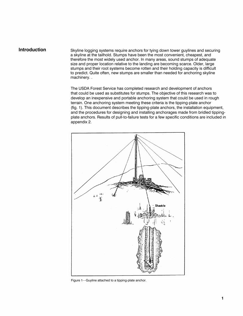
The USDA Forest Service has completed research and development of anchors that could be used as substitutes for stumps. The objective of this research was to develop an inexpensive and portable anchoring system that could be used in rough terrain. One anchoring system meeting these criteria is the tipping-plate anchor (fig. 1). This document describes the tipping-plate anchors, the installation equipment, and the procedures for designing and installing anchorages made from bridled tipping-plate anchors. Results of pull-to-failure tests for a few specific conditions are included in appendix 2.
, ,
Figure 1––Guyline attached to a tipping-plate anchor.
1

Tipping-Plate Anchors
Arrowhead Anchor
"
Holding capacities of these anchors differ greatly with the soil conditions and gen-erally are low enough so that two or more anchois must be bridled to provide a safe anchorage for a guyline or tailhold. Rigging and bridling procedures are important and are described, as are two design procedures for determining the number of anchors required to be bridled together to withstand the load. Both procedures re-quire the installation of single tipping-plate anchors and pulling them to failure or to some predetermined load. Extrapolation of test data from one site to another is not recommended unless a thorough investigation of the soils is made at both sites to determine if they have the same engineering properties.
Two anchors that we tested were the arrowhead anchor (Laconia Malleable Iron Company) and the Manta Ray anchor (Foresight Products, Inc.).1 A third, the soil toggle anchor, was designed and fabricated by the Forest Service and is now being produced by Foresight Products, Inc.
This anchor is shaped like an arrowhead and is cast with ductile iron. Two holes through the anchor allow attachment of, wire rope (fig. 2). The wire rope assembly may be single or double depending on the anchor size. The diameters of available wire rope are 1/8, 3/16, 1/4 and 5/16 inch. The anchor size is specified by the width as measured across the top at the broadest point. Arrowhead anchor sizes, bearing areas, weights, and cable diameters are shown in table 1.
1 The use of trade, firm, or corporation names in this publication is for the information and convenience of the reader. Such use does not constitute an official endorsement or approval by the U.S. Department of Agriculture of any product or service to the exclusion of others that may be suitable.
Figure 2––Arrowhead anchor.
2

Manta Ray Anchor
Soil Toggle Anchor
Installation Equipment
The Manta Ray anchors are 7 inches wide and 12 inches long, are made of mild steel, and weigh 12 pounds (fig. 3). A wire rope 3/4 or 5/8 inch in diameter is per-manently attached to the anchor with a pressed eye; the free end of the wire rope has a pressed eye with thimble.
Two sizes of soil toggle anchors are available (fig. 4). The smaller of the two is designed for 5/8 or 3/4 inch in diameter wire rope and the larger is designed fora 7/8 or 1 inch in diameter wire rope.
Three types of impact hammers can be used for driving Arrowhead and Manta Ray anchors: hydraulic, pneumatic, and gasoline. Hydraulic hammers require a power unit that can deliver a flow of 8 gallons per minute at a pressure of 2000 pounds per square inch. Construction equipment such as hydraulic backhoes, excavators, and yarders used for logging have hydraulic systems meeting these requirements. Unless the equipment can travel over steep and uneven terrain, however, anchor installations will be confined to a 200-foot radius from where the power unit is parked. A portable hydraulic power unit that can be carried into remote areas has been developed that meets the requirements for providing power to impact hammers. Pneumatic hammers require an air supply of at least 100 cubic feet per minute.
The hammers needed to drive anchors weigh between 60 and 90 pounds. The lighter weight hammer is used to drive the anchor in loose soils or when an augered pilot hole is used. A 90-pound hammer may be needed in dense or rocky soils if a pilot hole is not used. Some pnuematic hammers can drill holes with a rock bit and blow out the cuttings.
Gasoline-powered hammers, such as the Swedish-made Pionjar, require no external power supply and are portable. They weigh about 60 pounds and exert an impact force as well as a rotational force on the drive rod. A new model has been developed that devotes all its power to driving only; it may be able to install Arrowhead and Manta Ray anchors faster than previous models could.
Impact Hammers
3
Table 1––Physical characteristics of Laconia Arrowhead anchors made from malleable iron

Drive rods (sometimes called drive gads) transmit the reciprocating force from the impact hammer to the anchor and must be customized to fit the anchor. Most hydrau- lic and pneumatic hammers require a rod 1.125 or 1.25 inches in diameter. Some smaller hammers and the gasoline hammers use a rod 0.875 inch in diameter. The end of the rod that is inserted into the anchor needs to be machined for a tight clear-ance. If the clearance is too small, however, the anchor may become seized on the rod during installation. The rod should also be machined so that the end of the rod does not touch the bottom of the socket in the anchor.
Drive rods can be obtained in 2.5-, 4.0-, and 5.5-foot lengths. The rods used for driving Manta Ray anchors are designed so that sections may be coupled together; rods for other anchors are a fixed length. A disadvantage of using fixed-length rods is that the depth an anchor is driven to is limited by the length of the rods. Also, if a 5.5-foot rod is used to start the driving operation, the operator will be required to hold the hammer about 6 feet above the ground. This may require standing on something to gain the proper working elevation. If the rods are shorter and additional sections can be added as the anchor is driven, the operator is usually working with the hammer below shoulder height, which is easier and safer.
Augering Equipment Many gasoline- and hydraulic-powered portable augers can auger holes 4 to 8 inches in diameter. Auger extension flights can be obtained in several lengths and diameters to suit various conditions. Carbide tips are recommended for most forest soils. Manufacturer's specifications on installation equipment are given in appendix 3.
Figure 3––Manta Ray anchor.
4
Drive Rods

Figure 4––Small and large soil toggle anchors.
Installation Procedures
The installation procedures differ with the type of soil and anchor. For small anchors (such as a 2-inch Arrowhead) in soft soils, the anchor is driven into the ground with a drive rod and a sledge hammer or with a driving device similar to that used for steel fenceposts. The drive rod is inserted into the hole at the top of the anchor; the anchor is positioned so that the cable faces the direction of pull and is driven at the desired angle until it cannot be driven further or the desired depth is reached––which should not be less than 36 inches. The rod is then removed, and the anchor is "set" or "keyed" so that the major plane of the anchor will be about 90 degrees to the angle of pull. This is done by pulling the anchor until the anchor strap has been pulled 8 to 12 inches out of the ground.
Anchors
For the larger Arrowheads (6-inch size or larger) and Manta Rays, a hydraulic, pneu- matic, or gasoline-driven impact hammer is needed to install the anchor. The installa- tion procedure is the same as for the drive rod and sledge hammer, except that the hammer is placed on the drive rod before the rod is inserted into the anchor.
In denser soils, such as dense clays, a pilot hole can be augered before the anchor is driven. With a Manta Ray anchor, for example, a 4-inch pilot hole is augered at least 6 inches deeper than the design depth. This leaves an area at the bottom of the hole for loose soil to accumulate in. After the hole is augered, the anchor is driven by using the pilot hole as a guide. Because the Manta Ray anchor is 7 inches wide, 3 inches of its width is driven through the undisturbed soil. Once the anchor is at the desired depth, the rod is pulled out and the hole is filled with soil and tamped. The anchor must be set as described above.
5

Rigging and Bridling
6
The additional time and equipment required to auger a pilot hole before the anchor is driven is offset by several advantages. With the Arrowhead anchors, retrieving the drive rod after the anchor is driven becomes difficult if a pilot hole is not used. The friction of the soil on the rod is enough to require a mechanical pulling device for retrieval. The time needed to drive an anchor by using a pilot hole is less than with- out a pilot hole. If an obstacle is encountered during the augering process, the auger can be pulled up and moved to a new hole location. If an obstacle is first encountered when the anchor is driven, however, the anchor could become damaged; it would be very difficult to retrieve the anchor to move it to another location.
Most tests that we did by using a pilot hole were with an augered hole. In rocky soils, it may be easier to make a pilot hole by using a rock bit and impact hammer. In soft soils and at shallow depths, driving a pointed rod into the soil may be adequate for a pilot hole.
Both the Arrowhead anchor and the Manta Ray anchor are installed by being driven into the ground. The soil toggle anchor is installed by dropping it down an augered hole. The smaller soil toggle requires a hole 6 inches in diameter, and the larger model requires a hole 8 inches in diameter. The soil toggle has a wing on each end, one blunt and the other sharp (fig. 4). The anchor is placed blunt end down in the hole. This allows the anchor to slide down the hole without catching on a root or other obstacle. After the hole is filled and tamped, the anchor is set. The pointed wing at the top will dig into the side of the hole and cause the anchor to rotate to its load-holding position.
The depth of installation 'for any of the three anchor types should be decided by the type of soil. The minimum depth should be 4 feet for the Arrowhead anchor, 5 feet for the Manta Ray and small soil toggle anchors, and 8 feet for the large soil toggle anchor.
The angle of installation should be decided after the direction of pull relative to the slope of the ground is determined, as discussed below under "Prepare Detailed Design of Anchorages." In general, for upslope and downslope pulls, the anchor should be installed perpendicular to the ground surface. As the angle of pull nears perpendicular to the ground, the anchor should be installed vertically. The objective is to avoid having the direction of pull in line with the direction of installation and to maximize the distance of undisturbed soil between the installed anchor and the ground surface in the direction of pull. Refer to the discussion below and figure 5. It is recommended that a trench be dug along the direction of pull so that the attach-ment cable tends to dig into the side of the installation hole and pulls the anchor toward undisturbed soil.
In most cases, more than one anchor will be needed to obtain the holding capacity required to restrain the skyline or guyline. Multiple anchors will have to be bridled into an anchorage. The individual anchors in a bridled anchorage must be installed far enough apart so that they do not bear on the same soil mass.

7
Figure 5––Angle of installation relative to ground slope. Angles shown should be used only as a guide.
It is important that the blocks of a nonrigid bridle system be kept clean and free of dirt. Small amounts of dirt or other debris jammed between the wire rope and the sheave can cause unequal tension across the block and more tension on one anchor than the other.
In the rigid bridle system, the tieback lines should be the same diameter as the anchor strap. The shackle connecting the eyes of the tieback lines to the eye of the guyline or skyline must be 1/8 inch larger than the larger line, rated for a load equal to or greater than the expected working load, and large enough to accom-modate all the eyes from the tieback lines.
Since the length of the tie-back lines must be individually adjusted, the free end is threaded through the eye of the anchor strap, pulled tight with a hand operated racheting winch, and clamped using three or four wire rope clamps.

Safety
Anchor Design Guide
Determine Logging System Requirements
Investigate Site
8
Although tipping-plate anchors are fairly easy to install by using the procedures outlined above, the work is sometimes physically demanding and requires advance preparation and attention to safety while in the field. The following suggestions will reduce injuries and help to reduce the cost of anchor installation.
• Wear personal protective gear when installing anchors. Earplugs should be worn when impact hammers are in use. Goggles and other types of eye and face pro-tection should be worn at all times because of the chance of injury from flying
particles. • Use proper methods for lifting the auger from the hole or lifting the hammer onto the drive rod to prevent back injuries. • Read instruction manuals before using equipment and test all equipment before
taking it to the field to ensure that it is in good working condition. • Plan each installation and make sure all needed tools, rigging hardware, fuel,
and miscellaneous supplies are available. • Inform each crew member of the procedures and discuss any hazardous
conditions. • Install anchors with the strap facing the direction of pull. The soil toggle is
installed with the blunt end down. • Make sure that the threaded connecting sections of the drive rods used for in-
stalling Manta Ray anchors are well greased with an all-purpose grease so that the 2.5-foot-long sections can be separated easily.
The general procedure for planning anchor installations has six steps:
1. Determine logging system requirements. 2. Investigate site. 3. Select anchor and installation equipment. 4. Conduct feasibility tests. 5. Do a detailed design of anchorages. 6. Estimate costs.
The first step is to review the sale design to determine the logging equipment that will be used. The intent is to determine the maximum loads that may be transmitted to the anchors. These should be estimated by noting the location of the guylines (or the tailhold), which will require tipping-plate anchors, and the breaking strength of the rigging used for these components.
The design load of the anchor will be determined by the breaking strength of the wire rope used for rigging guylines or tailholds. The values used for the breaking strength of the wire rope are published by wire rope manufacturers.
The location of the anchor point will influence what equipment is used to install the anchor. This is discussed below under "Select Anchor and Installation Equipment"
For a particular anchor design, the primary variables influencing its holding capacity are depth of installation, soil strength, and moisture content of the soil.

H
Select Anchor and Installation Equipment
Conduct Feasibility Tests
Before the type and number of anchors are selected, the site conditions must be assessed. This is done by walking the site to estimate potential locations for anchor installations and to determine the characteristics of the soil at these locations. It should be determined whether a hole can be augered with the portable augering equipment. This will determine to a large extent what type of anchor to use. Other factors that should be assessed are the likely seasonal variation in soil moisture and the likelihood of encountering obstacles during the anchor installation.
Portable augering equipment should be used to drill several exploratory holes as deeply as possible at the proposed site. Test holes should be marked so that they can be found later. The date, detailed site description, soil description, and equip-ment used for exploration should be recorded in a drill log.
The soil should be classified according to the Unified Soil Classification System (American Society for Testing Materials 1988a), the standard penetration test (American Society for Testing Materials 1988b) should be performed, and the soil moisture content should be determined. This information can be used as more experience is gained to develop a correlation between holding capacity and soil conditions for particular depths of installation.
After the initial investigation of the site, a preliminary selection of anchor should be made so that feasibility tests can be conducted. This preliminary selection will depend on the results of the initial site investigation and the diameter of wire rope to be anchored. Table 2 can be used in the following way to select the anchor: Start in the left column and find the correct soil condition. Then move horizontally to the center column to see if the wire rope diameter agrees. Move down the column as necessary to find the correct combination. The preliminary selection of anchor type and procedure is given in the right column.
If during a site investigation, for example, cobbles too large for an auger to bring to the surface are found (but a hole 2 inches in diameter can be drilled), then either a Manta Ray or Arrowhead anchor would be selected. If the wire rope diameter is 5/8 inch or larger, the preliminary anchor selection would be the Manta Ray. If the the wire rope diameter is less than 5/8 inch, then both the Manta Ray and Arrow- head could be tested to determine which will provide the greatest holding capacity with the fewest anchors.
The equipment chosen for installing the anchor will depend on the anchor selected and the difficulty of access to the site. Use table 3 as a guide to the recommended installation equipment. Table 8 in appendix 3 gives a detailed list of the recom- mended equipment.
Although we have results from pullout tests (Copstead 1988), specific correlations between holding capacity and measured soil characteristics are not good. Data from some of these tests are shown in appendix 2. Because the tests were done in only a few soil types, and rigorous soil investigations were not always done, the results should be used for preliminary selection only and not for detailed designs. The holding capacity of an anchor in a specific soil type and location should be determined by onsite feasibility tests. Conducting feasibility tests will also uncover any installation problems that could affect installation costs.
9

10
Table 2––Preliminary selection of anchor type
If a few anchors are installed under conditions identical to the conditions expected for the production anchor installation and pulled to failure, and the maximum holding capacity of each anchor is recorded, then the number of anchors required to be bridled together for the production situation can be calculated. Two methods for this calculation are given below in the section "Prepare Detailed Design of Anchorages."

11
Table 3––Installation equipment and access guide

These calculations depend on three assumptions.
1. All pullout tests are conducted under identical conditions so that variation in the results is attributable only to random effects of the test.
2. The anchors used for restraining the skyline or guyline (that is, the production anchors) are installed under the same conditions as were the test anchors.
3. The scheme used to bridle the anchors together is 100 percent efficient. (The concept of bridling efficiency is explained below under "Multiple-anchor holding capacity.")
The procedure for conducting feasibility tests starts with the installation of anchors according to procedures described earlier. The anchor testing equipment is attached to each anchor, and the anchor is pulled to failure or to a load that is sufficient ac-cording to the design methods outlined below. The anchor testing equipment consists of a hydraulic cylinder and equipment to activate it (usually a hydraulic power unit), instruments for measuring loads, and the rigging needed to connect the cylinder to the anchor strap on one side and a fixed reaction point on the other side. The hydraulic cylinder and power unit should be able to exert at least a 50,000-pound force on the anchor strap. The cylinder should be capable of at least a 2-foot stroke.
The minimum instrumentation system required for conducting the feasibility tests is a calibrated pressure gauge connected to the high-pressure side of the hydraulic cylinder. For safety reasons, the gauge should be located near the controls for the hydraulic power unit. The pressure-gauge/hydraulic-cylinder system should be calibrated during feasibility tests over the range of loads expected by using a load measuring device of known accuracy and precision. The pressure indicated on the gauge may depend on the temperature of the hydraulic oil in the system as well as on the pulling force. The measuring system should be calibrated with the same cylinder and setup configuration that will be used during the actual tests.
Another available instrumentation system measures force directly with a mechanical gauge, such as a Dillon dynamometer, or with a strain gauge load cell and electronic indicator. These devices are available with peak indicators so that the maximum force occurring during the test is easily recorded. These systems are easy to calibrate and use and are not sensitive to oil temperature variations as the pressure gauge system is. Force measurement systems can be calibrated independently from the hydraulic cylinder.
What rigging is used for the test depends on the individual situation. Load ratings for the rigging should be equal to or greater than the maximum load the equipment can produce (at least 50,000 pounds) or to the rated breaking strength of the strap attached to the anchor.
12

The procedure for the feasibility tests is to connect and tension all rigging. The rigging usually will have to be repeatedly tensioned and the cylinder restroked, because the deflection of the anchor will usually exceed the 2-foot stroke of the hydraulic cylinder before its failure load or before 50,000 pounds of tension is reached. The maximum load reading (or pressure reading, if a calibrated pressure gauge is used) should be recorded. A gauge incorporating a peak indicator is recommended.
.
Designing an anchorage means determining how many individual anchors need to be bridled together to stabilize the system, how deep and at what angle they are installed, how far apart they should be, and how they are bridled. The detailed design is based mainly on the results of the feasibility tests.
Number of anchors for an anchorage––Tests conducted so far have shown that few, if any, easily installed earth anchors can withstand the high forces in cable-logging systems; therefore, several anchors must be bridled together for each guyline or tailhold. Two methods are given here for determining how many indi-vidual anchors need to be bridled together. For the first, the designer must judge the maximum force the anchored wire rope must withstand––this force is less than the breaking strength of the wire rope. The second method is based on the break-ing strength of the wire rope.
1. Procedure based on estimating the maximum force:
a. Determine the maximum force to be exerted on the anchorage. Lacking any other information, use two-thirds of the breaking strength of the wire rope being anchored.
b. Perform pullout tests of anchors as described above under "Conduct Feasibility Tests." Pullout capacities will be measured and recorded during these tests.
c. Calculate the sample mean and standard deviation of the pullout test results.
d. Calculate two ratios:
e. Using the chart of figure 6, find the number of anchors to use by locating the intersection of the value for Fp/X (along the vertical axis) and S/X (along the hori- zontal axis). The lines extending from the left side of the chart to the right and sloping downward demarcate zones corresponding to the number of anchors re- quired foe an anchorage. If the intersection of the ratios calculated in step c above falls on a line, then the number of anchors to use is given in the zone above the line. This chart has been calculated assuming five tests were done (charts for 8 and 20 tests are in appendix 1).
13
Prepare Detailed Design of Anchorages

Figure 6––Number of anchors to install based on the ratio of expected force, Fp, to mean pullout force, X, and on the ratio of sample standard devidtion, S, to mean pullout force for five feasibility tests. See appendix 1 for charts based on number of feasibility tests greater than five.
The number of anchors in figure 6 is set so that there is a 95-percent chance that 95 percent of the bridled anchor installations at the test site installed identically to the test anchors will fail at a load higher than the maximum force (obtained in step a) exerted on the anchorage.
2. Procedure based on wire rope breaking strength:
a. Determine the maximum force that will be exerted on the anchorage assuming that the guylines or the tailhold will be tensioned to the breaking strength of the wire rope.
b. Perform pullout tests of anchors as described elsewhere in this guide. Pullout
capacities will be measured and recorded during these tests.
c. Calculate the number of anchors required by dividing the force obtained in step (a) by the mean pullout force for the tests in step (b) and rounding up to the nearest integer.
14

Both of the above methods make use of the results of feasibility tests at a site to indicate the probable holding capacity. The two methods usually give similar results. The first method gives the number of anchors required to hold the actual expected force with a predetermined probability of success. The second method uses the difference between the actual force exerted on the rigging and the breaking strength of the rigging as a margin of safety. These methods should be used only as guides to deciding the number of anchors to specify for each anchorage.
The designer will have to judge how well the assumptions stated above are met and take this into account when specifying the anchorage design.
It is important to remember three things when the results from a small number of tests are applied to anchorage design.
1. The tests may show that an anchor is viable for use with logging equipment for the circumstances of the testing, but extrapolating the results to new installation sites should be done very carefully. The best way to assess what the pullout force might be at a new site is to install new test anchors and pull them to failure.
2. Although some results showed that anchors pulled from an angle of 70 to 85 degrees away from the axis of installation had pullout forces at least 15 percent greater than those measured for pulls coincident with the installation axis, this may not be true for all situations. Feasibility tests should be done with the loading angle as close to that expected for the production anchor installation.
3. The effect of soil moisture content on the pullout force has not been established conclusively. Soil moisture content may vary throughout the year so that the pullout capacity for otherwise identical installations may differ throughout the year.
The two methods for determining how many individual anchors need to be bridled together are illustrated in example 1.
15
Example 1 Calculation. Feasibility tests have been done at a site where earth anchors will probably have to be used. The tests gave the following pullout forces in pounds: 34,300 35,800 33,600 34,900 36,000 How many anchors should be installed for each production anchorage if the rated breaking strength of the single-part guylines to be anchored is 192,000 pounds?

Solution Using the first method, we estimate the maximum force exerted on the anchorage will be two-thirds of the rated breaking strength or 128,000 pounds. The sample mean and standard deviation are 34,920 and 1008 pounds, respectively. We then calculate the two ratios: Fp/X = 128,000/34,920 = 3.67 and S/X = 1,008/34,920 = 0.03 .
Because five tests were done, we use the chart for N=5 (fig. 6) and read that four anchors are needed.
Using the second method, we divide the rated breaking strength of the wire rope by the mean of the pullout forces for the feasibility tests: 192,000/34,920 = 5.5 anchors required .
According to the second method, six anchors are needed.
In this example, the first method shows that fewer anchors are required, but the first method will not always result in smaller estimates. Large differences in the test results will cause the number of anchors required by the first method to be higher but will not affect the results given by the second method.
Multiple-anchor holding capacity––One of the assumptions that the calculations in example 1 depend on is that the bridle design is 100 percent efficient. In fact, the holding capacity of a group of anchors is not usually equal to the holding capacity of one anchor multiplied by the number of anchors in the group (Kovacs and Yokel 1979). Kovacs and Yokel (1979) point out:
Many efficiency ("efficiency" is the ratio between the group capacity and the sum of the capacities of the individual piles) formulas are available for the unwary engineer to use in computing the ultimate capacity of a pile [or anchor] group. None of these formulas take into account the factors that actually govern the ultimate capacity of the...group itself. Likewise, there are no hard and fast rules to use when predicting the pullout capacity of multiple anchors.
Two factors affecting the capacity of a multiple-anchor cluster are the degree to which loads are shared among the individual anchors of the cluster and the degree to which individual anchors in a cluster act on separate soil masses. If loads are not adequately shared among clustered anchors, then one anchor may reach its maxi-mum load capability before the others, and the maximum holding capacity of the entire anchorage will be some fraction of the capacity of a 100-percent-efficient anchorage. Because the load capacity of a soil anchor depends partially on the soil mass mobilized, two anchors sharing the same soil mass will have less ultimate capacity than if they operated on separate soil masses.
16
u
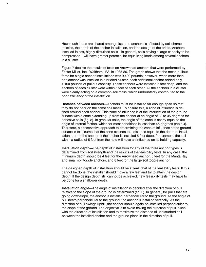
How much loads are shared among clustered anchors is affected by soil charac-teristics, the depth of the anchor installation, and the design of the bridle. Anchors installed in soft, highly disturbed soils––in general, soils having a large capacity to be compressed––will have greater potential for equalizing loads among several anchors in a cluster.
Figure 7 depicts the results of tests on Arrowhead anchors that were performed by Foster-Miller, Inc., Waltham, MA, in 1985-86. The graph shows that the mean pullout force for single-anchor installations was 9,400 pounds; however, when more than one anchor was installed in a bridled cluster, each additional anchor added only 4,100 pounds of pullout capacity. These anchors were installed 5 feet deep, and the anchors of each cluster were within 5 feet of each other. All the anchors in a cluster were clearly acting on a common soil mass, which undoubtedly contributed to the poor efficiency of the installation.
Distance between anchors––Anchors must be installed far enough apart so that they do not bear on the same soil mass. To ensure this, a zone of influence is de- fined around each anchor. This zone of influence is at the intersection of the ground surface with a cone extending up from the anchor at an angle of 28 to 35 degrees for cohesive soils (fig. 8). In granular soils, the angle of the cone is nearly equal to the angle of internal friction, which for most conditions is less than 45 degrees (table 4). Therefore, a conservative approach to determining the zone of influence at the ground surface is to assume that the zone extends to a distance equal to the depth of instal-lation around the anchor. If the anchor is installed 5 feet deep, for example, the soil within a radius of 5 feet from the hole will have an influence on its holding capacity.
Installation depth––The depth of installation for any of the three anchor types is determined from soil strength and the results of the feasibility tests. In any case, the minimum depth should be 4 feet for the Arrowhead anchor, 5 feet for the Manta Ray and small soil toggle anchors, and 8 feet for the large soil toggle anchor.
The designed depth of installation should be at least that of the feasibility tests. If this cannot be done, the installer should move a few feet and try to attain the design depth. If the design depth still cannot be achieved, new feasibility tests may have to be done for a shallower depth.
Installation angle––The angle of installation is decided after the direction of pull relative to the slope of the ground is determined (fig. 5). In general, for pulls that are going downslope, the anchor is installed perpendicular to the ground. As the angle of pull nears perpendicular to the ground, the anchor is installed vertically. As the direction of pull swings uphill, the anchor should again be installed perpendicular to the slope of the ground. The objective is to avoid having the direction of pull in line with the direction of installation and to maximize the distance of undisturbed soil between the installed anchor and the ground plane in the direction of pull.
17

18
The rigging for each individual anchor should be designed to support the expected load so that if an anchor becomes lodged behind a tree root or rock the rigging will not fail.
Bridle design––The primary function of a bridle for anchoring is to prevent soil and mechanical failure by ensuring that loads are shared evenly among component anchors (Foster-Miller, Inc. 1986). The problem is complicated by the different de-flection responses of individual anchors, which can result from differences in installed depth, soil type, and backfilling technique. Bridle performance is most critical in stiff soils where little deflection occurs before anchor or component failure occurs. In soft soils, however, bridle performance may not be as important because anchors may move several feet before full load is attained.
Figure 7––Cluster pullout capacity vs. the number of anchors in a cluster. Tests were performed by Foster-Miller, Inc. (Unpublished data on file with: R. Copstead, Pacific Northwest Research Station, Forestry Sciences Laboratory, 4043 Roosevelt Way N.E. Seattle, WA 98105.)

19
Figure 8––Zone of influence of cohesive soils.
Table 4––Soil parameter correlations for granular soils

Bridling systems are either rigid or nonrigid. Rigid systems are not completely load-sharing because the initial unstretched length of each tieback line is fixed (fig. 9). The nonrigid type uses blocks to equalize the tensions in the tieback lines from each anchor (fig. 10). Thus, each anchor is required to hold its share of the load. An example of the nonrigid type is the "parachute" bridle system (Foster-Miller, Inc. 1984)
20
Figure 9––Example of a rigid bridle.
Figure 10––Example of a nonrigid bridle.

In soft soils, rigid nonload-sharing bridles can be used, because even with dif- ferences in initial tieback line tensions the entire bridle system will move until the anchors have developed sufficient load capacity to resist the imposed load. If one anchor in the rigidly bridled system fails, the system will often adjust and may hold the load long enough for operations to be shut down safely. On the other hand, with a nonrigid bridling system, if one anchor fails, the entire system can fail because of the large resulting deflection. The safety margin of the nonrigidly bridled anchor system cannot exceed the safety margin of the weakest anchor in the system.
Stiff soils cause anchors to reach maximum loads with small deflections. If some anchors in a rigidly bridled system are installed with poor backfill or in softer soil conditions than other anchors in the system, then the bridle will distribute a larger share of the load to the "good" anchors and may cause these anchors to fail before the others. The load would then be transferred to the adjacent anchors, which in turn would be overloaded. A remedy is to tighten the loose tieback lines by hand until the loads equalize or until it is determined that the weak anchors will never equally share the load. Even the most careful adjustment of tieback line lengths on a rigid, nonload-sharing bridle will result in some slack lines because anchors tend to set in slightly different distances. Thus, for the case of very stiff soils, a rigid bridling system requires more attention to initial tieback length adjustment. It may be appropriate to use a nonrigid bridling system in very stiff soils.
The advantages and disadvantages of the two bridle types are summarized in table 5.
21
Table 5––Advantages and disadvantages of bridle designs

Estimate Costs
-
Some examples follow of figuring cost estimates for Manta Ray and soil toggle anchors.
Cost estimate for Installing a Manta Ray anchor––The estimate is based on the following prices and assumptions:
• Crew consists of two people at $18.00 per hour including fringe benefits. • Cost of owning and operating a pickup is $0.50 per mile. • Average travel distance to sale area is 100 miles. • The anchor point is one-fourth of a mile from the road. Two people are needed to
move the auger to the anchor point. One person has to carry the hammer, and one person has to carry the anchors and miscellaneous equipment.
• It takes 2 minutes to auger a pilot hole and 5 minutes to drive the anchor. • It takes 10 minutes to move to the next hole and 30 minutes to move to next
anchor point. • It takes 15 minutes to stake out anchor locations at each anchor point. • Owning and operating cost, including depreciation, for all installation equipment is $9.00 per hour. • Anchors with straps cost $70 each.
Based on the above assumptions, the cost to move all equipment to the first instal-lation point is $370.00. For each anchor add the cost of installation, $82.00. For each additional anchor point, add $12.00 to move equipment and stake out anchor locations.
Cost estimate for installation of soil toggle anchor––The estimate is based on the following prices and assumptions:
• Two people in crew at $18.00 per hour including fringe benefits. • Cost of owning and operating a pickup is $0.50 per mile. • Average travel distance to sale area is 100 miles. • The anchor point is one-fourth of a mile from the road. Two people are needed to
move the auger to the anchor point. For each anchor, two trips are needed to carry the anchor, straps, and miscellaneous equipment.
22

• It takes 2 minutes to auger a 6-foot hole, 7 minutes for a 9-foot hole, 14 minutes for a 12-foot hole, and 23 minutes for a 15-foot hole.
• It takes 10 minutes to move to the next hole and 30 minutes to move to next anchor point.
• It takes 15 minutes to put anchor in hole and backfill. • It takes 30 minutes to stake out anchor locations at each anchor point. • Owning and operating cost, including depreciation, for all installation equipment
is $4.50 per hour. • Anchors with straps cost $150 each.
The cost to move all equipment to the first installation point, based on the above assumptions, is $350.00. For each anchor add the cost of installation which depends on the depth of installation: 6 feet = $188.00,9 feet = $192.00, 12 feet = $197.00, and 15 feet = $200.00. For each additional anchor point, add $41.00 to move equipment and stake out anchor locations.
23

Literature Cited
24
American Society for Testing and Materials. 1988a. Designation D 2487-85: test method for classification of soils for engineering purposes. In: 1988 Annual book of ASTM standards. Philadelphia: American Society for Testing and Materials. Vol. 4.08.
American Society for Testing and Materials. 1988b. Designation D 1586-84: standard method for penetration test and split-barrel sampling of soils. In: 1988 Annual book of ASTM standards. Philadelphia: American Society for Testing and Materials: 216-219. Vol. 4.08.
Copstead, Ronald lo 1988. Results of tests on earth anchors for cable logging systems. In: International mountain logging and Pacific Northwest skyline sym-posium: 1988 December 12-16; Portland, OR. [Place of publication unknown]: [Publisher unknown]: 42-48. Sponsored by: Department of Forest Engineering, College of Forestry, Oregon State University; International Union of Forest Research Organizations, Mountain Logging Section.
Foster-Miller, Inc. 1984. Engineering tradeoff analysis report for SEAS conceptual designs. Rep. FSS-8266-R-016. [Location of publisher unknown]: [Publisher un-known]. Prepared for: U.S. Department of Agriculture, Forest Service; contract 53-91 S8-2-94. 250 p.
Foster-Miller, Inc. 1986. Substitute earth anchoring system (SEAS) bridle test report. Rep. FSS-8266-R-027. [Location of publisher unknown]: [Publisher unknown]. Prepared for: U.S. Department of Agriculture Forest Service; contract 53-91 S8-2-94. 38 p.
Johnson, N.lo; Welch, B.lo 1940. Applications of the non-central t-distribution. Biometrika. March: 362-389.
Kovacs, W.D.; Yokel, F.Y. 1979. Soil and rock anchors for mobile homes––a state- of-the-art report. National Bureau of Standards Building Science Series 107.
Washington, DC: U.S. Department of Commerce. 164 p.
Wallis, W.A. 1947. Use of variables in acceptance inspection for percent defective. In: Selected techniques of statistical analysis for scientific and industrial research and production and management engineering. 1 st ed. New York: McGraw-Hill: 7-93.

Additional References
A.B. Chance Co. 1977. Encyclopedia of anchoring. Bull. 4-7706. [Location of publisher unknown]: [Publisher unknown]. 58 p. Available from: A.B. Chance Co., 210 N. Allen St., Centralia, MO 65240.
Foster-Miller, Inc. 1987. Substitute earth anchoring system (SEAS) anchor selection––preliminary evaluation. Rep. FSS-8266-R-047. [Location of publisher unknown]: [Publisher unknown]. Prepared for: U.S. Department of Agriculture, Forest Service; contract 53-91 S8-2-94. 139 p.
Hanna, Thomas, H. 1982. Foundations in tension––ground anchors. Clausthal, Germany: Trans Tech Publications. 573 p.
Kovacs, Austin; Blouin, S.; McKelvy, B.; Colligan, H. 1975. On the theory of ground anchors. Tech. Rep. 258. Hanover, NH: Cold Regions Research and Engineering Laboratory, U.S. Army Corps of Engineers. 77 p.
Obradovich, John N.; Dulin, Robert O. 1982. A study of available anchor systems and development of concepts suitable for application to meet cable-logging and/or assault vehicle egress requirements. Rep. R 0300.011-2. Fort Belvoir, VA: U.S. Army Mobility Equipment Research and Development Command. 2 vol.
U.S. Department of Agriculture, Forest Service. 1978. Substitute anchor systems––bibliographies and abstracts of reports and lists of patents. Proj. Rec. 7824 1201
for ED&T project 2640. San Dimas, CA: San Dimas Equipment Development Center. 56 p.
25

Appendix 1 : Charts for Determining Number of Anchors to Install
The charts on the following pages (figs. 11, 12, and 13) were constructed according to the following equation:
where Fp = expected load.
x = average pullout force for the feasibility tests.
m = number of anchors.
k = function of the probability level, confidence coeffient, and the number of feasibility tests done and is obtained following the method of Wallis (Wallis 1947), and Johnson and Welch (Johnson and Welch 1940). Also includes a factor to convert the sample standard deviation to an unbiased estimator of standard deviation.
s = sample standard deviation of the pullout force for the feasibility tests. It is calcualted using n - 1 in the denominator.
The charts are calculated with a probability level of 0.95 and a confidence coefficient of 0.95; that is, a 95-percent chance exists that 95 percent of the birdied anchorages (consisting of anchors tested under the same conditions as the feasibility tests and combined with a 1 DO-percent efficient bridling system) will have pullout forces equal to or greater than the expected force. Values of k used for the charts are tabulated below.
26

27
Figure 11––Number of anchors to install based on the ratio of expected force, Fp, to mean pullout force, X, and on the ratio of sample standard deviation, S, to mean pullout force for 8 feasibility tests.

28
Figure 12––Number of anchors to install based on the ratio of expected force, Fp, to mean pullout force, X, and on the ratio of sample standard deviation, 8, to mean pullout force for 17 feasibility tests.

29
Figure 13––Number of anchors to install based on the ratio of expected force, Fp, to mean pullout force, X, and on the ratio of sample standard deviation, S, to mean pullout force for 145 feasibility tests.

Appendix 2: Measured Anchor Pullout Forces
Tables 6 and 7 show results of tests of three types of tipping plates for anchoring in earth (Copstead 1988). The tests were done at simialr installations at several locations in California, Oregon, and Washington. All anchors were 5 feet deep.
30
Table 6––Description of anchor test locations

31
Table 7––Pullout forces, in thousands of pounds, for anchors installed to 5-foot depth
Appendix 3: Specifications for Anchors and Installation Equipment
Plonjar Gas-Powered Impact Hammers
Little Beaver Gas- Powered Earth Drills
32
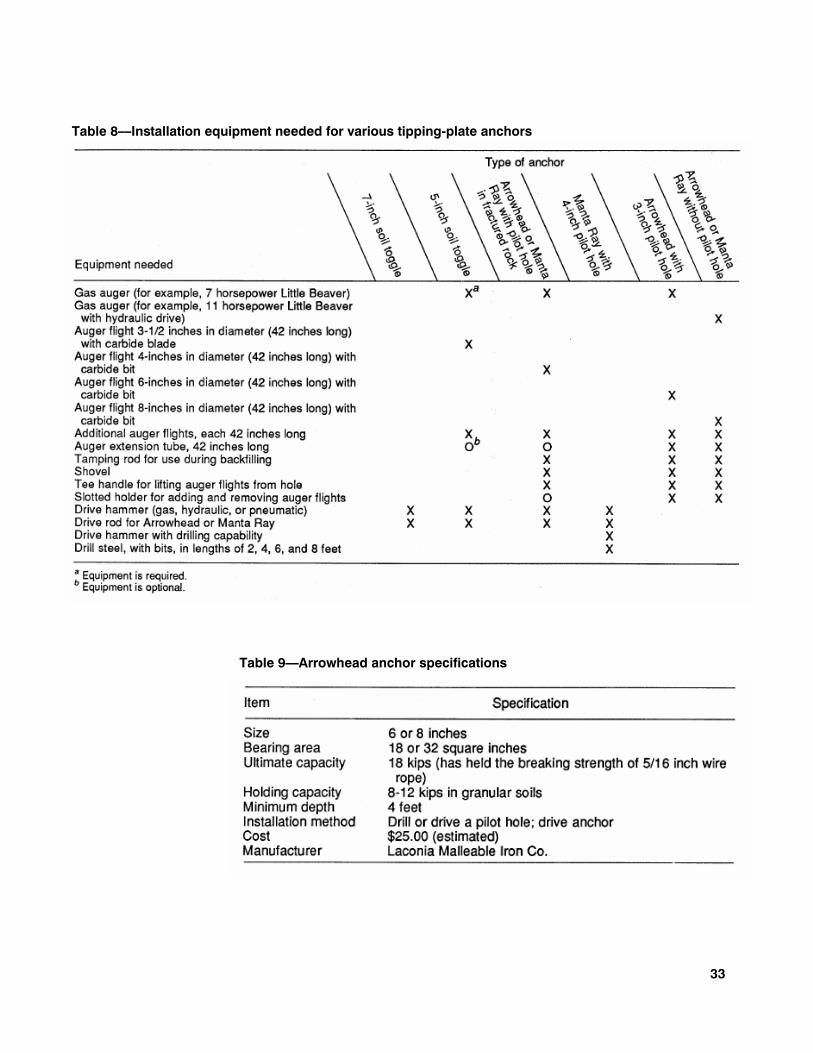
Table 8 shows which equipment is required to install the various anchor types. Tables 9, 10, and 11 give specificatins for Arrowhead. Manta Ray and soil tottle tipping plate anchors. Information is also given on the earth drills and portable gasoline-powered impact hammers that we used. These are typical of the equipment required to install earth anchoras for cable logging.
We have used two models of gasoline-powered impact hammers to install earth anchors. The Pionjar model 120 is a combined rock drill and impact hammer. The operator can switch from drilling to breaking (pounding) by moving a lever. As an impact hammer, the unit is comparable to medium size pneumatic hammers and drills. The Pionjar model 130 is the same as the Pionjar model 120 except that is does not have the rotation mechanism and thus has fewer moving parts; it is also lighter in weight.
Both the Pionjar model 120 and 130 have:
• Handles of vibration-absorbing material to suppress high-frequency vibrations • An adjustable choke and throttle control • An air filter that will allow operation in dusty environments • A power takeoff for attaching accessories (for example, a drill steel grinder for a
winch) • Some specifications for these hammers are given in table 12
We have used two models of Little Beaver earth drills to install earth anchors. The Little Beaver model 7 is a mechanical earth-drilling system that includes power plant, power takeoff, and adaptors for variety of augers. The 11-horsepower hydraulically driven model was used with a handle designed for two operators and should be used for augering holes 6 or 8 inches diameter.
Both models are designed with a 7-foot-long "torque tube" that minimizes the torque felt by the operator while augering holes. Some other features are:
• Reversible blades on augers. • A reversing valve on the hydraulic model so that power unit can be used to help
free a stuck auger • A 10:1 gear reduction transmission (20:1 is also available) causes the auger to
rotate at an easily controllable rate • Eight inches in diameter semipneumatic wheels • A snap-on adaptor for augers ranging from 1-1/2 to 16 inches in diameter
Model 7 (not including torque tube or fuel) weighs 130 pounds; the hydraulically driven unit weights 172 pounds.
33
Table 8––Installation equipment needed for various tipping-plate anchors
Table 8––Installation equipment needed for various tipping-plate anchors
Table 9––Arrowhead anchor specifications

34
Table 10––Manta Ray anchor specifications
Table 11––Soil toggle anchor specifications

35
Table 12––Specifications for Pionjar gasoline-powered impact hammers

Copstead, Ronald L.; Studier, Donald D. 1990. An Earth anchor system: installation and design guide. Gen. Tech. Rep. PNW-GTR-257. Portland, OR: U.S. Department of Agriculture, Forest Service, Pacific Northwest Research Station. 35 p.
A system for anchoring the guylines and skylines of cable yarding equipment is pre-sented. A description of three types of tipping plate anchors is given. Descriptions of the installation equipment and methods specific to each type are given. Procedures for determining the correct number of anchors to install are included, as are guide-lines for installing the anchors so that they will reliably withstand the forces imposed on them in this application. Charts for determining the number of anchors to install and bridle together are included. Information presented is based on field tests con-ducted under various of conditions in California, Oregon, and Washington. Keywords: Logging, anchors, cable yarding, machine anchors, soft earth anchoring.
The Forest Service of the U.S. Department of Agriculture is dedicated to the principle of multiple use management of the Nation's forest resources for sustained yields of wood, water, forage, wildlife, and recreation. Through forestry research, cooperation with the States and private forest owners, and management of the National Forests and National Grasslands, it strives––as directed by Congress––to provide increasingly greater service to a growing Nation.
The U.S. Department of Agriculture is an Equal Opportunity Employer. Applicants for all Department programs will be given equal consideration without regard to age, race, color, sex, religion, or national origin.
Pacific Northwest Research Station 319 S.W. Pine St. P.O. Box 3890 Portland, Oregon 97208

U.S. Department of Agriculture Pacific Northwest Research Station 319 S.W. Pine Street P.O. Box 3890 Portland, Oregon 97208 Official Business Penalty for Private Use, $300
BULK RATE POSTAGE + FEES PAID USDA-FS
PERMIT No. G-40
Do NOT detach Label