Unit7A SS Bear2 - Bearings Design - VTU
7
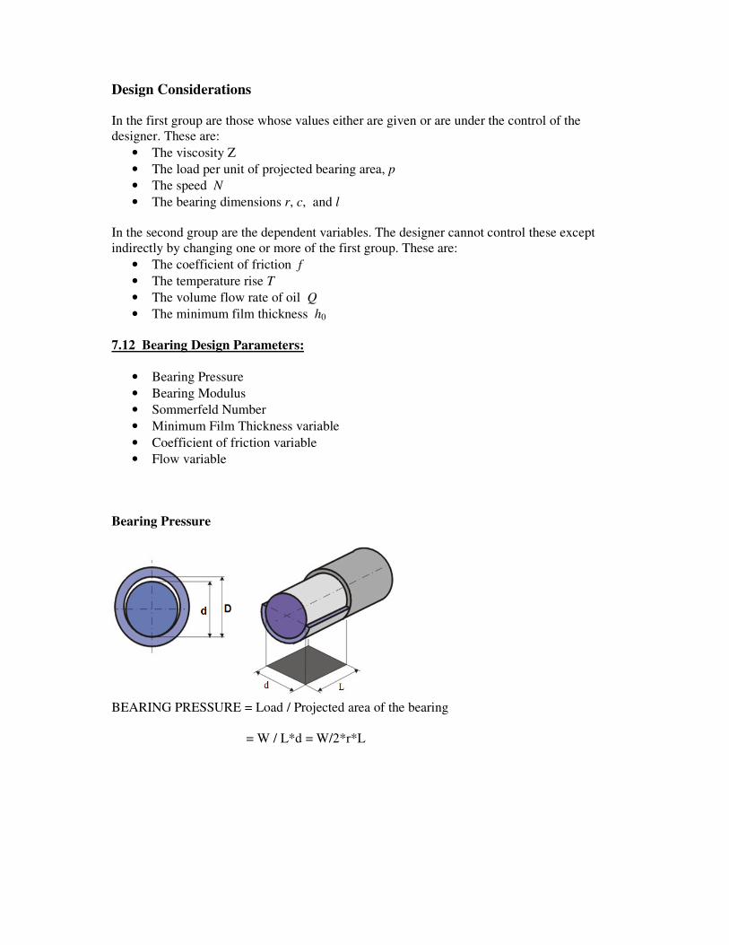
Design Considerations In the first group are those whose values either are given or are under the control of the designer. These are: • The viscosity Z • The load per unit of projected bearing area, p • The speed N • The bearing dimensions r, c, and l In the second group are the dependent variables. The designer cannot control these except indirectly by changing one or more of the first group. These are: • The coefficient of friction f • The temperature rise T • The volume flow rate of oil Q • The minimum film thickness h 0 7.12 Bearing Design Parameters: • Bearing Pressure • Bearing Modulus • Sommerfeld Number • Minimum Film Thickness variable • Coefficient of friction variable • Flow variable Bearing Pressure BEARING PRESSURE = Load / Projected area of the bearing = W / L*d = W/2*r*L
-
Upload
onkar-kakad -
Category
Documents
-
view
27 -
download
1
description
Bearings - VTU
Transcript of Unit7A SS Bear2 - Bearings Design - VTU
Design Considerations
In the first group are those whose values either are given or are under the control of the
designer. These are:
• The viscosity Z
• The load per unit of projected bearing area, p
• The speed N�
• The bearing dimensions r, c, and l
In the second group are the dependent variables. The designer cannot control these except
indirectly by changing one or more of the first group. These are:
• The coefficient of friction f
• The temperature rise T
• The volume flow rate of oil Q
• The minimum film thickness h0
7.12 Bearing Design Parameters:
• Bearing Pressure
• Bearing Modulus
• Sommerfeld Number
• Minimum Film Thickness variable
• Coefficient of friction variable
• Flow variable
Bearing Pressure
BEARING PRESSURE = Load / Projected area of the bearing
= W / L*d = W/2*r*L
If L/d is > 1, the bearing is said to be a long bearing.
If L/d is < 1, the bearing is said to be a short bearing.
If L/d is = 1, the bearing is said to be a Square bearing.
If the length of the bearing is very large compared to its diameter, L/d= ∞, such a bearing is
said to be an idealized bearing with no side leakage.
The load carrying capacity of long bearing is better than that of the short bearings. From the
point of view of reduced side leakage, long bearings are preferable. However, space
requirements, manufacturing tolerances, Heat carrying capacity and shaft deflections are
better met with short bearings.
For general purpose machinery L/d= 1 to 2.
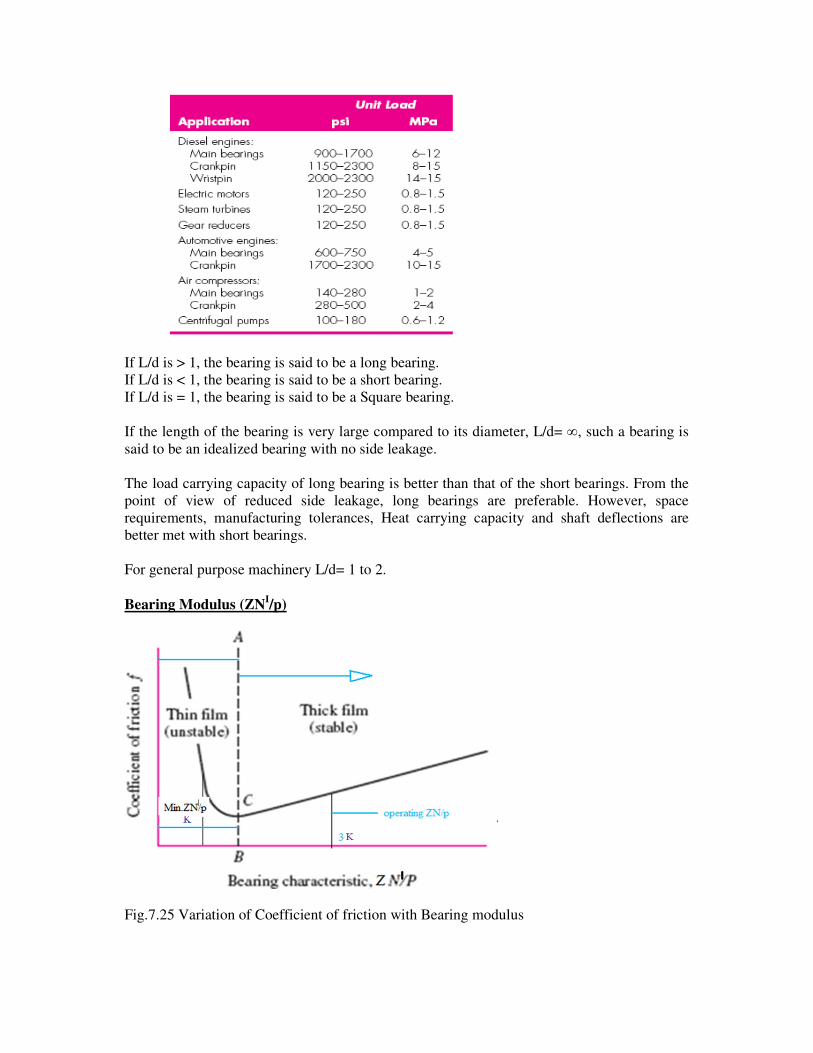
Bearing Modulus (ZNI/p)
Fig.7.25 Variation of Coefficient of friction with Bearing modulus
Bearing Modulus is a dimensionless parameter on which the coefficient friction in a bearing
depends (Fig.7.25). In the region to the left of Point C, operating conditions are severe and
mixed lubrication occurs. Small change in speed or increase in load can reduce ZN′/p and a
small education in ZN′/p can increase the coefficient of friction drastically. This increases
heat which reduces the viscosity of the lubricant. This further reduces ZN′/p leading to further
increase in friction.
This has a compounding effect on the bearing leading to destruction of Oil film and resulting
in metal to metal contact. In order to prevent such conditions, the bearing should operate with
a ZN′/p at least three times the minimum value of the bearing modulus (K).
Suppose we are operating to the right of the line BA and there is an increase in lubricating
temperature. This results in lower viscosity and hence a smaller value of the ZN′/p. The
coefficient of friction decreases, and consequently the lubricating temperature drops. Thus
the region to the right of line BA defines “stable lubrication” because the variations are self
correcting.
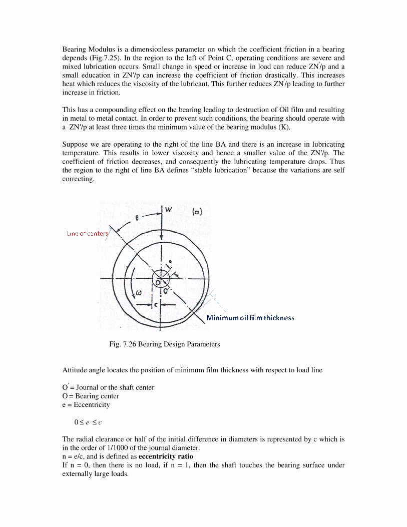
Fig. 7.26 Bearing Design Parameters
Attitude angle locates the position of minimum film thickness with respect to load line
O′
= Journal or the shaft center
O = Bearing center
e = Eccentricity
The radial clearance or half of the initial difference in diameters is represented by c which is
in the order of 1/1000 of the journal diameter.
n = e/c, and is defined as eccentricity ratio
If n = 0, then there is no load, if n = 1, then the shaft touches the bearing surface under
externally large loads.
ce ≤≤0

Using the above figure 7.26, the following relationship can be obtained for ‘h’
h= c(1+ n cosθ)
The maximum and minimum values of ‘h’ are:
hmax= c+e = c(1+n)
hmin = c-e = c(1-n)
The relationship between attitude, radial clearance and minimum oil film thickness is given
by:
n= 1- (ho/c)
Sommerfeld number
The bearing characteristic number, or the Sommerfeld number, is defined by
S= (ZN′/p) (r/c)2
The Sommerfeld number is very important in lubrication analysis because it contains many of
the parameters that are specified by the designer.
The parameter r/c is called the radial clearance ratio.
The relation between Sommerfeld number and Attitude of the bearing is shown in the figure
7.27.
Fig.7.27 Attitude v/s Sommerfeld number
If S=0.15 or greater than 0.15, the bearing is a Lightly loaded bearing.
If S is lesser than 0.15, the bearing is a Heavily loaded bearing.
In Raimondi and Boyd method, the performance of a bearing is expressed in terms of
dimensionless parameters The results of their work is available in the form of charts and
tables.
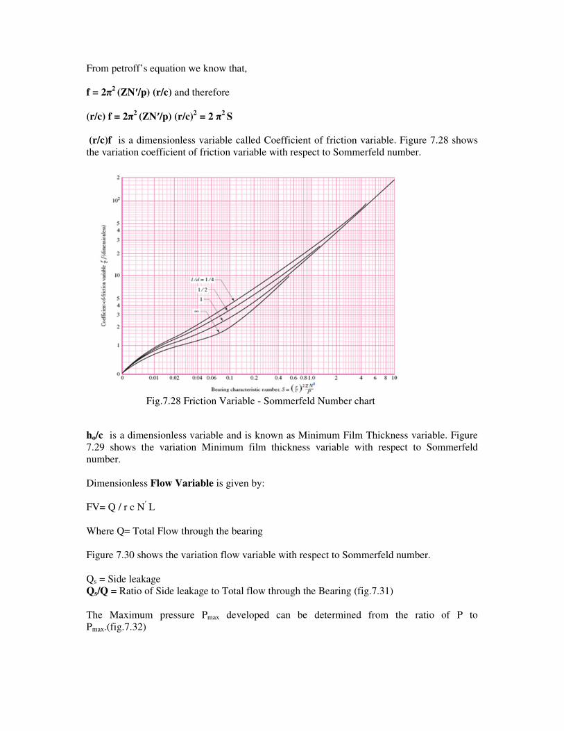
From petroff’s equation we know that,
f = 2π2
(ZN′/p) (r/c) and therefore
(r/c) f = 2π2
(ZN′/p) (r/c)2 = 2 π
2 S
(r/c)f is a dimensionless variable called Coefficient of friction variable. Figure 7.28 shows
the variation coefficient of friction variable with respect to Sommerfeld number.
Fig.7.28 Friction Variable - Sommerfeld Number chart
ho/c is a dimensionless variable and is known as Minimum Film Thickness variable. Figure
7.29 shows the variation Minimum film thickness variable with respect to Sommerfeld
number.
Dimensionless Flow Variable is given by:
FV= Q / r c N′ L
Where Q= Total Flow through the bearing
Figure 7.30 shows the variation flow variable with respect to Sommerfeld number.
Qs = Side leakage
Qs/Q = Ratio of Side leakage to Total flow through the Bearing (fig.7.31)
The Maximum pressure Pmax developed can be determined from the ratio of P to
Pmax.(fig.7.32)
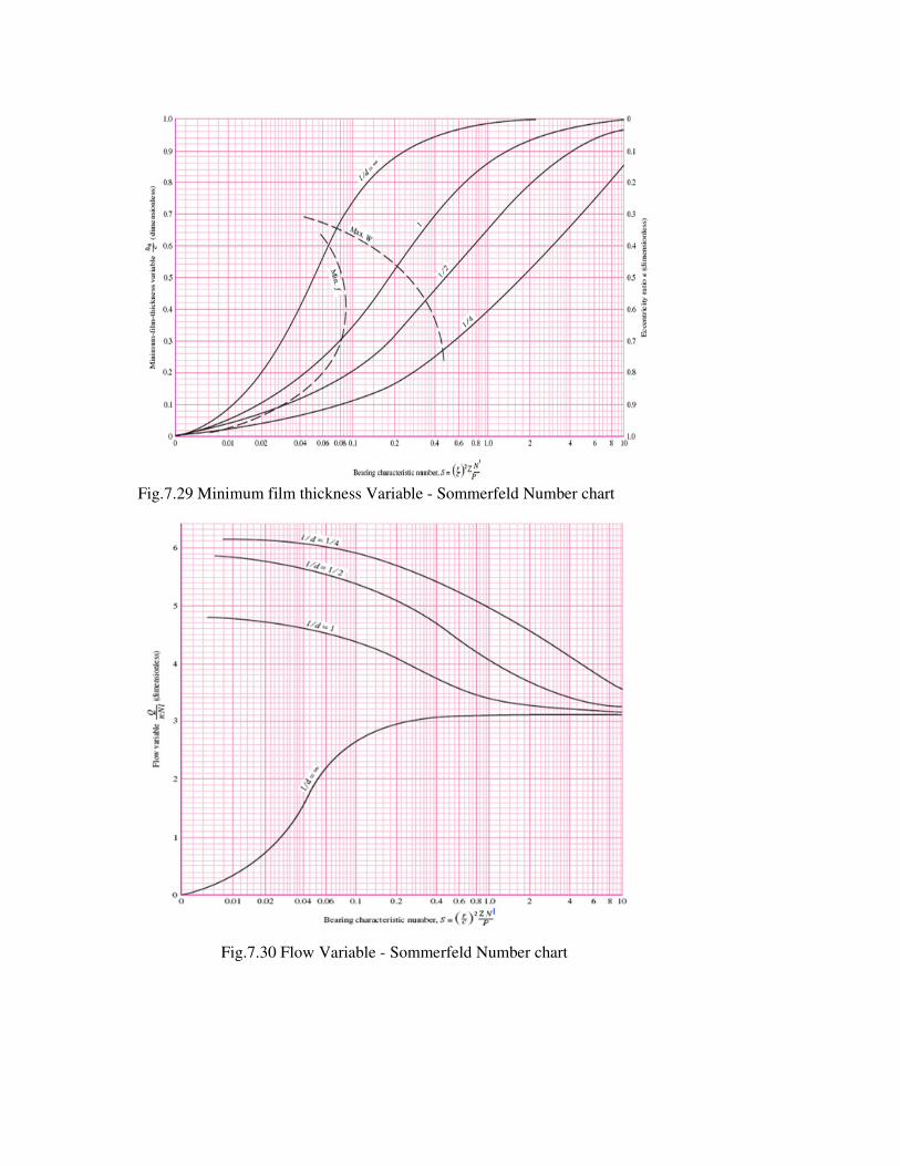
Fig.7.29 Minimum film thickness Variable - Sommerfeld Number chart
Fig.7.30 Flow Variable - Sommerfeld Number chart
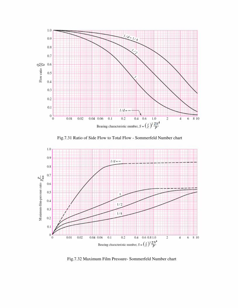
Fig.7.31 Ratio of Side Flow to Total Flow - Sommerfeld Number chart
Fig.7.32 Maximum Film Pressure- Sommerfeld Number chart