UNIT t 1 DC Circuit Unit-01/Lecture- 01 - rgpvonline.com Circuit Unit-01/Lecture- 01 Sources can be...
73
http://www.rgpvonline.com UNIT – 1 DC Circuit Unit-01/Lecture-01 Sources can be either independent or dependent upon some other quantities. i) Independent Sources [RGPV Dec 2014] a) Voltage Source- [RGPV June 2013] Voltage source is defined as the energy source which gives constant voltage across its terminals irrespective of the current drawn through its terminals. The symbols for ideal voltage source is shown in fig. this is connected to load, at any terminals the value of voltage at load terminals remains same. b) Current Source- It is the source which gives constant current at its terminals irrespective of the voltage appearing across its terminals. the symbol for current source is shown in fig (a).this is connected to the load as shown in fig. at any time its value is same irrespective of voltage across its terminals. ii) Dependant Source Dependant source are those source whose value of source depends on voltage or current in the circuit. such sources are indicated by diamond and further classified as :- (i)Voltage dependant voltage source (ii) voltage dependant current source (iii) Current dependant current source (iv) Current dependant voltage source http://www.rgpvonline.com http://www.a2zsubjects.com
Transcript of UNIT t 1 DC Circuit Unit-01/Lecture- 01 - rgpvonline.com Circuit Unit-01/Lecture- 01 Sources can be...
http://www.rgpvonline.com
UNIT – 1
DC Circuit
Unit-01/Lecture-01
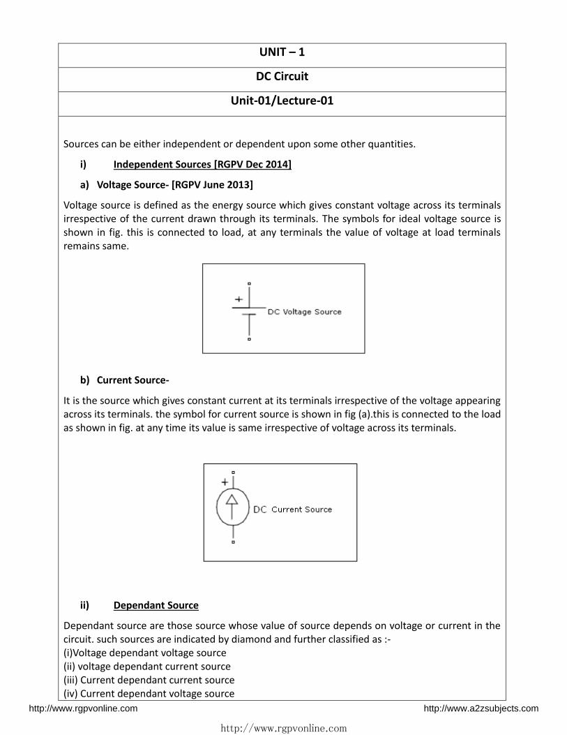
Sources can be either independent or dependent upon some other quantities.
i) Independent Sources [RGPV Dec 2014]
a) Voltage Source- [RGPV June 2013]
Voltage source is defined as the energy source which gives constant voltage across its terminals
irrespective of the current drawn through its terminals. The symbols for ideal voltage source is
shown in fig. this is connected to load, at any terminals the value of voltage at load terminals
remains same.
b) Current Source-
It is the source which gives constant current at its terminals irrespective of the voltage appearing
across its terminals. the symbol for current source is shown in fig (a).this is connected to the load
as shown in fig. at any time its value is same irrespective of voltage across its terminals.
ii) Dependant Source
Dependant source are those source whose value of source depends on voltage or current in the
circuit. such sources are indicated by diamond and further classified as :-
(i)Voltage dependant voltage source
(ii) voltage dependant current source
(iii) Current dependant current source
(iv) Current dependant voltage source
http://www.rgpvonline.com http://www.a2zsubjects.com

http://www.rgpvonline.com
Ohm's law
Ohm's law states that at constant temperature, the current through a conductor between two
points is directly proportional to the potential difference across the two points.
V= I R
Where, I is the current through the conductor in units of amperes,
V is the potential difference measured across the conductor in units of volts, and
R is the resistance of the conductor in units of ohms ( R in this relation is constant,
independent of the current)
Kirchhoff’s Curre t La - [RGPV Feb. 2010]
Algebraic sum of currents at a node is zero conversely algebraic sums of currents flowing
towards a node is equal to algebraic sum of currents flowing away from the node.
At A Node-
I1+I2+I3-I4-I5=0
I1+I2+I3= I4+I5
http://www.rgpvonline.com http://www.a2zsubjects.com

http://www.rgpvonline.com
Kirchhoff’s Voltage La -
Algebraic sum of voltages in a close loop is zero conversely in a close loop algebraic sums of emfs
are equal to algebraic sum of voltage drops.
e-v1-v2=0
e=v1+v2
S.NO RGPV QUESTIONS Year Marks
Q.1 Explain Voltage Source and Current Source June 2013 4
Q.2 “tate a d e plai Ki hoff s u e t a d Voltage la Feb 2010 4
http://www.rgpvonline.com http://www.a2zsubjects.com
http://www.rgpvonline.com
Unit-01/Lecture-02
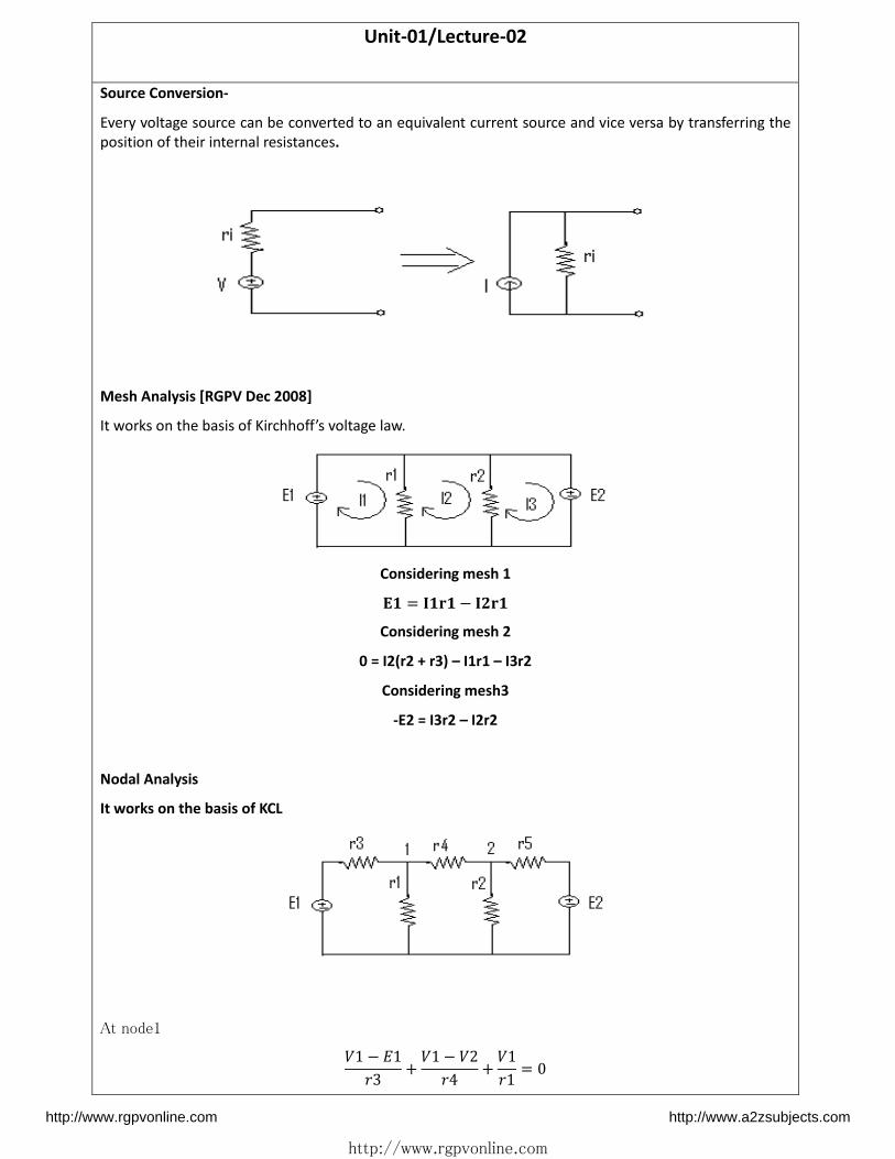
Source Conversion-
Every voltage source can be converted to an equivalent current source and vice versa by transferring the
position of their internal resistances.
Mesh Analysis [RGPV Dec 2008]
It o ks o the asis of Ki hhoff s oltage la .
Considering mesh 1 � = � − �
Considering mesh 2
0 = I2(r2 + r3) – I1r1 – I3r2
Considering mesh3
-E2 = I3r2 – I2r2
Nodal Analysis
It works on the basis of KCL
At node1 − � + − + =
http://www.rgpvonline.com http://www.a2zsubjects.com

http://www.rgpvonline.com
At node 2
− + + − � =
Q. Calculate the current through 5 ohm resistance using loop analysis-
Loop 1 � × + � − � =
Loop 2 � × + � − � + � − � =
Loop 3 � × + � − � = −
⌊ −− −− ⌋ × [��� ]=[− ] I1=11.3A
I2=12A
I3=6.7A
S.NO RGPV QUESTIONS Year Marks
Q.1 Calculate the current through 5 ohm resistance using
loop analysis-
Dec 2013 7
Q.2 State and explain Mesh analysis to solve a network Dec 2008 10
http://www.rgpvonline.com http://www.a2zsubjects.com

http://www.rgpvonline.com
Unit-03/Lecture-03
Superposition Theorem [RGPV June 2013][Dec 2010]
In a linear active bilateral network containing more than one source. The current through any branch is the
algebraic sum of currents flowing thorough the branch when we consider one source at a time while
replacing all other sources by their internal resistances.
Considering current source first Deactivating voltage source by its internal resistance, therefore making it
short at the terminals.
At node 1 + + − =
At node 2 − + − � =
Now considering voltage source and deactivating current source by its internal resistance,
therefore making it open at the terminals.
http://www.rgpvonline.com http://www.a2zsubjects.com

http://www.rgpvonline.com
At node1 − � + + − =
At node 2 − + =
Q. Determine branch current using Superposition Theorem. [RGPV Feb 2010]
Step 1- Considering 12 V source
I = . A
I = . A
I = . A
Step 2- Considering 32 V source
I = . A I = . A
I = . A
I =I -I = . -0.85=0.17A
I =I -I = . -0.93=1.2A
I =I +I = . + . = . A
http://www.rgpvonline.com http://www.a2zsubjects.com
http://www.rgpvonline.com
Unit-01/Lecture-04
The e i ’s theore [RGPV Dec. , Ju e ]
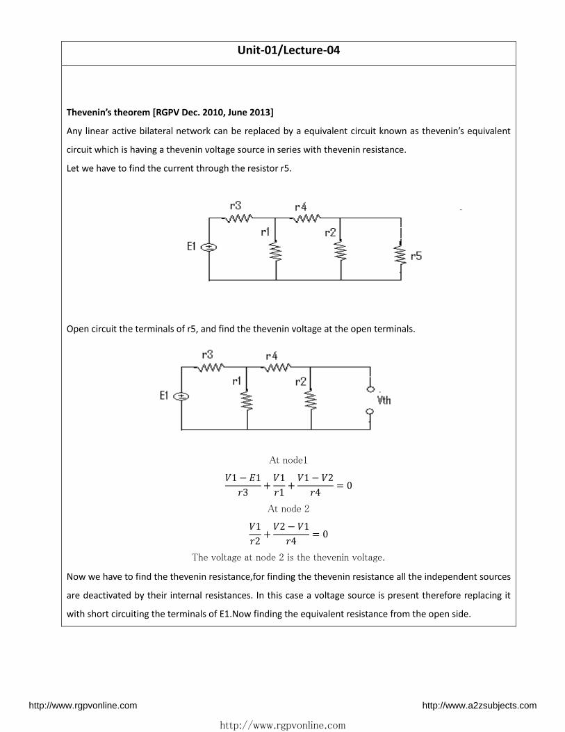
Any linear a ti e ilate al et o k a e epla ed a e ui ale t i uit k o as the e i s e ui ale t
circuit which is having a thevenin voltage source in series with thevenin resistance.
Let we have to find the current through the resistor r5.
Open circuit the terminals of r5, and find the thevenin voltage at the open terminals.
At node1 − � + + − =
At node 2 + − =
The voltage at node 2 is the thevenin voltage.
Now we have to find the thevenin resistance,for finding the thevenin resistance all the independent sources
are deactivated by their internal resistances. In this case a voltage source is present therefore replacing it
with short circuiting the terminals of E1.Now finding the equivalent resistance from the open side.
http://www.rgpvonline.com http://www.a2zsubjects.com
http://www.rgpvonline.com
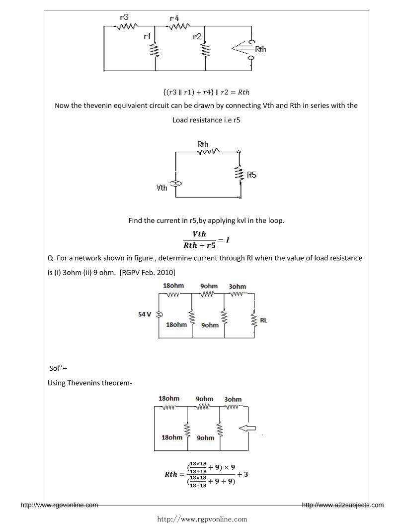
{ ∥ + } ∥ = ℎ
Now the thevenin equivalent circuit can be drawn by connecting Vth and Rth in series with the
Load resistance i.e r5
Find the current in r5,by applying kvl in the loop.
� + = �
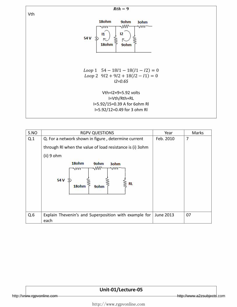
Q. For a network shown in figure , determine current through Rl when the value of load resistance
is (i) 3ohm (ii) 9 ohm. [RGPV Feb. 2010]
Soln –
Using Thevenins theorem-
� = ×+ + ××+ + + +
http://www.rgpvonline.com http://www.a2zsubjects.com
http://www.rgpvonline.com
� =
Vth
− � − � − � = � + � + � − � =
I2=0.65
Vth=I2×9=5.92 volts
I=Vth/Rth+RL
I=5.92/15=0.39 A for 6ohm Rl
I=5.92/12=0.49 for 3 ohm Rl
S.NO RGPV QUESTIONS Year Marks
Q.1 Q. For a network shown in figure , determine current
through Rl when the value of load resistance is (i) 3ohm
(ii) 9 ohm
Feb. 2010 7
Q.6 E plai The e i s a d “upe positio ith e a ple for
each
June 2013
07
Unit-01/Lecture-05 http://www.rgpvonline.com http://www.a2zsubjects.com

http://www.rgpvonline.com
Star Delta Transformation- [RGPV April 2009]
Star to delta
Ra = R1R3/(R1+R2+R3)
Rb= R1R2/(R1+R2+R3)
Rc = R3R2/(R1+R2+R3)
Delta to star
R1 = (RaRb + RbRc + RcRa)/Rc
R2 = (RaRb + RbRc + RcRa)/Ra
R3 = (RaRb + RbRc + RcRa)/Rb
S.NO RGPV QUESTIONS Year Marks
Q.1 Deduce the relation for conversion from Star to Delta
Circuit
April 2009 10
http://www.rgpvonline.com http://www.a2zsubjects.com

http://www.rgpvonline.com
UNIT – 2
1-phase AC Circuits
Unit-02/Lecture-01
Generation of Sinusoidal Waveforms
By application of Electromagnetism, an electric current flowing through a conductor can be used
to generate a magnetic field around itself, and also if a single wire conductor is moved or rotated
within a stationary magnetic field, an EMF , (Electro-Motive Force) will be induced within the
conductor due to this movement.
A relationship exists between Electricity and Magnetism giving us, the effect of Electromagnetic
Induction and it is this basic principal that electrical machines and generators use to generate a
Sinusoidal Waveform for our mains supply.
An AC generator uses the principal of Faraday’s electromagnetic induction to convert a
mechanical energy such as rotation, into electrical energy, a Sinusoidal Waveform. A simple
generator consists of a pair of permanent magnets producing a fixed magnetic field between a
north and a south pole. Inside this magnetic field is a single rectangular loop of wire that can be
rotated around a fixed axis allowing it to cut the magnetic flux at various angles as shown below.
As the coil rotates anticlockwise around the central axis which is perpendicular to the magnetic
field, the wire loop cuts the lines of magnetic force set up between the north and south poles at
different angles as the loop rotates. The amount of induced EMF in the loop at any instant of time
is proportional to the angle of rotation of the wire loop.
As this wire loop rotates, electrons in the wire flow in one direction around the loop. Now when
http://www.rgpvonline.com http://www.a2zsubjects.com

http://www.rgpvonline.com
the wire loop has rotated past the 180o point and moves across the magnetic lines of force in the
opposite direction, the electrons in the wire loop change and flow in the opposite direction. Then
the direction of the electron movement determines the polarity of the induced voltage.
So we can see that when the loop or coil physically rotates one complete revolution, or 360o, one
full sinusoidal waveform is produced with one cycle of the waveform being produced for each
revolution of the coil. As the coil rotates within the magnetic field, the electrical connections are
made to the coil by means of carbon brushes and slip-rings which are used to transfer the
electrical current induced in the coil.
The amount of EMF induced into a coil cutting the magnetic lines of force is determined by the
following three factors.
• Speed – the speed at which the coil rotates inside the magnetic field.
• Strength – the strength of the magnetic field.
• Length – the length of the coil or conductor passing through the magnetic field.
http://www.rgpvonline.com http://www.a2zsubjects.com

http://www.rgpvonline.com
Unit-02/Lecture-02
AC CIRCUITS: [RGPV Dec. 2013]
Definitions
1) AC – The quantity which changes its magnitude and direction w.r.t. time is called an alternating
quantity (voltage or current).
2) Waveform- The shape of the curve obtained by plotting alternating quantity (voltage or current)
along X-axis is known as waveform.
3) Frequency- No. of cycles per second.
4) Time period- It is the time taken by any alternating quantity (voltage or current) to complete
1cycle.
5) Instantaneous Value- It is the value of an alternating quantity ( voltage or current)at a particular
instant of time.
6) Amplitude – It is the maximum value of waveform over a cycle. It is also known as crest value. It
is also called as peak value.
7) Average value- It is the arithmetic average of ac quantity over a complete cycle.
Iavg = Im / (�/2)
8) RMS value- RMS value is the root mean square value of an alternating quantity.RMS value of an
alternating quantity is given by that value of DC which will produce same amount of heat in same
duration of time in the same resistor as produced by AC.
Irms = Im / √
9) Power Factor- It is the Cosine angle between Voltage and current or it can be calculated by ratio
of resistance to impedance.
Relation between RMS value, Average value and Maximum value
Form Factor : It is the ratio between RMS value to average value.
F.F = RMS value / Average value
F.F = 1.11
Peak Factor : It is the ratio between maximum value to RMS value.
P.F = Maximum value / RMS value
P.F = 1.414
http://www.rgpvonline.com http://www.a2zsubjects.com

http://www.rgpvonline.com
Unit-02/Lecture-03
Definitions- [RGPV Feb. 2010]
Active Power : it is the power which is actually consumed in the circuit in any form (heat, light
etc.).it is also known as true power or real power and it is given by P = VICosφ its u it is att. Where φ is the angle between voltage and current.
Reactive Power : It is the power which not actually consumed in the circuit but oscillates from
source to load & load to source in a cycle.and it is given by Q = VISinφ VAR(Volt Ampere Reactive)
Apparent Power : It is the combination of active and reactive power and it is given by vector sum
of active and reactive power.it is given as S = VI its unit is VA(Volt Ampere)
Impedance
Electrical impedance is the measure of the opposition that a circuit presents to a current when a
voltage is applied. The symbol for impedance is usually Z and it may be represented by writing its
magnitude and phase in the form |Z|∠θ. In general, impedance will be a complex number, with
the same units as resistance, for which the SI unit is the ohm (Ω).
Resistance is a measure of the opposition of a circuit to the flow of a steady current; while
impedance takes into account not only the resistance but also dynamic effects (known as
reactance). The reactance forms the imaginary part of complex impedance whereas resistance
forms the real part.
Z=R+jX
Where,
Z is the impedance, measured in ohms.
R is the resistance, measured in ohms.
X is the reactance, measured in ohms.
.
Admittance
http://www.rgpvonline.com http://www.a2zsubjects.com

http://www.rgpvonline.com
The reciprocal of impedance is admittance (i.e., admittance is the current-to-voltage ratio).
Admittance is a measure of how easily a circuit or device will allow a current to flow. The SI unit of
admittance is the siemens (symbol S). Admittance is defined as
Y = 1/ Z
Where,
Y is the admittance, measured in Siemens
Z is the impedance, measured in ohms
The synonymous unit mho, and the symbol ℧.
Resistance is a measure of the opposition of a circuit to the flow of a steady current, while
impedance takes into account not only the resistance but also dynamic effects (known as
reactance). Likewise, admittance is not only a measure of the ease with which a steady current can
flow, but also the dynamic effects of the material's susceptance to polarization:
Y = G + j B ,
where
Y is the admittance, measured in siemens.
G is the conductance, measured in siemens.
B is the susceptance, measured in siemens.
Phasor Diagrams
sinusoidal waveforms of the same frequency can have a Phase Difference between themselves
which represents the angular difference of the two sinusoidal waveforms. Also the terms lead
and lag as well as in-phase and out-of-phase were used to indicate the relationship
of one waveform to the other with the generalized sinusoidal expression given as:
A(t) = Am sin(ωt ± Φ) representing the sinusoid in the time-domain form.
But when presented mathematically in this way it is sometimes difficult to visualise this angular or
phasor difference between two or more sinusoidal waveforms. One way to overcome this problem
is to represent the sinusoids graphically within the spacial or phasor-domain form by using Phasor
Diagrams, and this is achieved by the rotating vector method.
Basically a rotating vector, simply called a Phasor is a scaled line whose length represents an
AC quantity that has both magnitude ( peak amplitude ) and direction ( phase ) which is
frozen at some point in time.
http://www.rgpvonline.com http://www.a2zsubjects.com

http://www.rgpvonline.com
A phasor is a vector that has an arrow head at one end which signifies partly the maximum value
of the vector quantity ( V or I ) and partly the end of the vector that rotates.
A complete sine wave can be constructed by a single vector rotating at an angular velocity of ω =
2πƒ, where ƒ is the frequency of the waveform. Then a Phasor is a quantity that has both
Magnitude and Direction . Generally, when constructing a phasor diagram, angular
velocity of a sine wave is always assumed to be: ω in rad/s. Consider the phasor diagram below.
Concept of Power Factor
power factor comes into picture in AC circuits only. Mathematically it is cosine of the phase
difference between source voltage and current. It refers to the fraction of total power (apparent
power) which is utilized to do the useful work called active power.
Need for Power Factor Improvement
• Real power is given by P = VIcosφ. To transfer a given amount of power at certain voltage, the
electrical current is inversely proportional to cosφ. Hence higher the pf lower will be the current
flowing. A small current flow requires less cross sectional area of conductor and thus it saves
conductor and money.
• From above relation we saw having poor power factor increases the current flowing in conductor
and thus copper loss increases. Further large voltage drop occurs in alternator, electrical
transformer and transmission & distribution lines which gives very poor voltage regulation.
• Further the KVA rating of machines is also reduced by having higher power factor as,Hence, the
http://www.rgpvonline.com http://www.a2zsubjects.com

http://www.rgpvonline.com
size and cost of machine also reduced. So, electrical power factor should be maintained close to
unity.
Unit-02/Lecture-04
AC circuit containing pure resistance-
AC circuit containing pure resistance gives the relation between voltage and current in the ac circuit.
v =VmSin wt
i =Im Sin wt
Instantaneous power p = v*i
= Vrms Irms
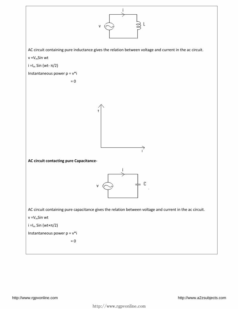
AC circuit contacting pure inductance-
http://www.rgpvonline.com http://www.a2zsubjects.com
http://www.rgpvonline.com
AC circuit containing pure inductance gives the relation between voltage and current in the ac circuit.
v =VmSin wt
i =Im Sin (wt- π/2)
Instantaneous power p = v*i
= 0
AC circuit contacting pure Capacitance-
AC circuit containing pure capacitance gives the relation between voltage and current in the ac circuit.
v =VmSin wt
i =Im Sin (wt+π/2)
Instantaneous power p = v*i
= 0
http://www.rgpvonline.com http://www.a2zsubjects.com

http://www.rgpvonline.com
Q. Obtain resultant voltage when two sources of emf having e1=100sinwt and e2 =100sin(wt-pi/6)
are connected in series. If the resultant voltage is applied to circuit of impedance (8+3j), calculate
the power supplied to the impedance.
Soln- Phasor of two voltages
= √ = .
= √ = .
According to law of parallogarm- = √ + + = √ . + . + . × . =
Current � = √ −
� =
Active power = � ∅ = × × cos − =
http://www.rgpvonline.com http://www.a2zsubjects.com

http://www.rgpvonline.com
S.NO RGPV QUESTIONS Year Marks
Q.1 obtain resultant voltage when two sources of emf having
e1=100sinwt and e2 =100sin(wt-pi/6) are connected in
series. If the resultant voltage is applied to circuit of
impedance (8+3j), calculate the power supplied to the
impedance.
June 2013 7
Q.8 Define the following the following
Average value, RMS value , Power Factor, Active Power,
Reactive power, Apparent Power
Dec 2013 07
Unit-02/Lecture-05-06
AC circuit contacting resistance and inductance in series
AC circuit containing resistance and inductance gives the relation between voltage and current in the ac
circuit.
v =VmSin wt
i =Im Sin (wt-φ)
Z = √ + � )
Instantaneous power p = v*i
= VICosφ
http://www.rgpvonline.com http://www.a2zsubjects.com

http://www.rgpvonline.com
AC circuit contacting resistance and capacitance in series
AC circuit containing resistance and capacitance gives the relation between voltage and current in the ac
circuit.
v =VmSin wt
i =Im Sin (wt+φ)
Instantaneous power p = v*i
= VICosφ
AC circuit contacting resistance, inductance and capacitance in series
AC circuit containing resistance,inductance and capacitance gives the relation between voltage and current
in the ac circuit.
http://www.rgpvonline.com http://www.a2zsubjects.com
http://www.rgpvonline.com
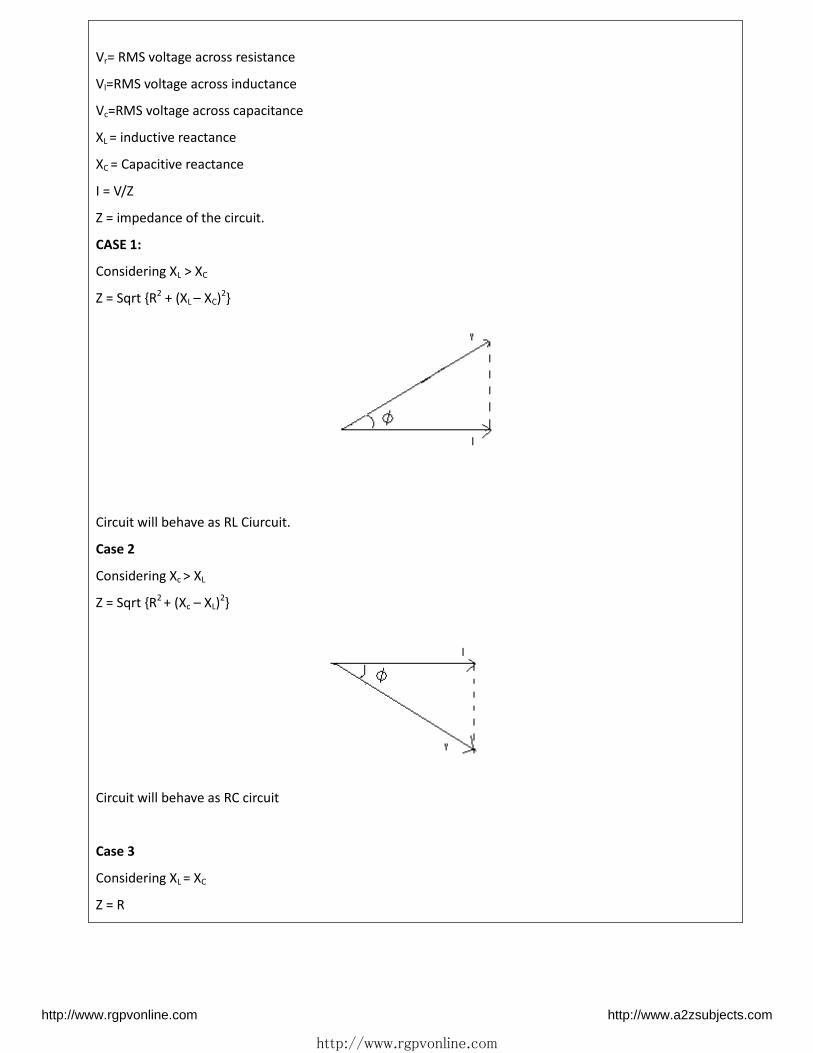
Vr= RMS voltage across resistance
Vl=RMS voltage across inductance
Vc=RMS voltage across capacitance
XL = inductive reactance
XC = Capacitive reactance
I = V/Z
Z = impedance of the circuit.
CASE 1:
Considering XL > XC
Z = Sqrt {R2 + (XL – XC)2}
Circuit will behave as RL Ciurcuit.
Case 2
Considering Xc > XL
Z = Sqrt {R2 + (Xc – XL)2}
Circuit will behave as RC circuit
Case 3
Considering XL = XC
Z = R
http://www.rgpvonline.com http://www.a2zsubjects.com

http://www.rgpvonline.com
Circuit will behave as resistive circuit.current in the circuit will be maximum.
It is also known as resonance condition.
Parallel RLC Circuit
Consider a RLC circuit in which resistor, inductor and capacitor are connected in parallel to each
other. This parallel combination is supplied by voltage supply, VS. This parallel RLC circuit is exactly
opposite to series RLC circuit. In series RLC circuit, the current flowing through all the three
components i.e the resistor, inductor and capacitor remains the same, but in parallel circuit, the
voltage across each element remains the same and the current gets divided in each component
depending upon the impedance of each component. That is why parallel RLC circuit is said to have
dual relationship with series RLC circuit.
http://www.rgpvonline.com http://www.a2zsubjects.com

http://www.rgpvonline.com
Phasor Diagram of Parallel RLC Circuit
Resonance in Parallel RLC Circuit
Like series RLC circuit, parallel RLC circuit also resonates at particular frequency called resonance
frequency i.e. there occurs a frequency at which inductive reactance becomes equal to capacitive
http://www.rgpvonline.com http://www.a2zsubjects.com
http://www.rgpvonline.com
reactance but unlike series RLC circuit, in parallel RLC circuit the impedance becomes maximum
and the circuit behaves like purely resistive circuit leading to unity electrical power factor of the
circuit.
UNIT – 3
3-phase AC Circuit
Unit-03/Lecture-01
http://www.rgpvonline.com http://www.a2zsubjects.com

http://www.rgpvonline.com
Advantages of a three phase system
The three phase power system has been adopted universally for transmission of AC power.
The advantages of a three phase system over a single phase system are:-
Higher power/weight ratio of alternators. A three phase alternator is smaller and lighter
that a single phase alternator of the same power output. Hence, it is also cheaper.
A three phase transmission system requires less copper or aluminium to transmit the
same quantity of power of a specific distance than a single phase system.
Three phase motors are self-starting due to the rotating magnetic field induced by the
three phases. On the other hand, a single phase motor is not self starting, it requires a
capacitor and an auxilliary winding.
In Single phase systems, the instanteous power(power delivered at any instant) is not
constant and is sinusoidal. This results in vibrations in single phase motors.
In a three phase power system, though, the instanteous power is always the same.
Three phase motors have better power factor compared to single phase motors.
Three phase supply can be rectified into dc supply with a lesser ripple factor
Polyphase circuits
Polyphase systems have three or more energized electrical conductors carrying alternating
currents with a definite time offset between the voltage waves in each conductor.
In a polyphase system the phase displacement between the phases is given by ;
Phase diffe e e = ⁰/
Where n is the no. of phases.
For a three phase system
p.d = 360/3
= ⁰
Phase Sequence
Phase rotation, or phase sequence, is the order in which the voltage waveforms of a polyphase
AC source reach their respective peaks. For a three-phase system, there are only two possible
phase sequences: 1-2-3 and 3-2-1, corresponding to the two possible directions of alternator
rotation.
http://www.rgpvonline.com http://www.a2zsubjects.com

http://www.rgpvonline.com
Unit-03/Lecture-02,03&04
3-phase STAR connection
In star connection, there is four wire, three wires are phase wire and fourth is neutral which is
taken from the star point. Star connection is preferred for long distance power transmission
because it is having the neutral point. In this we need to come to the concept of balanced and
unbalanced current in power system.
When equal current will flow through all the three phases, then it is called as balanced current.
And when the current will not be equal in any of the phase, then it is unbalanced current. In this
case, during balanced condition there will be no current flowing through the neutral line and
hence there is no use of the neutral terminal. But when there will be unbalanced current flowing
in the three phase circuit, neutral is having a vital role. It will take the unbalanced current
through to the ground and protect the transformer. Unbalanced current affects transformer and
it may also cause damage to the transformer and for this star connection is preferred for long
distance transmission.
Relation between line voltage and phase voltage, line current and phase current in Star
Connection.
http://www.rgpvonline.com http://www.a2zsubjects.com

http://www.rgpvonline.com
VL = √3 Vph
IL = Iph
3-phase Delta connection
In delta connection, there is three wires alone and no neutral terminal is taken. Normally delta
connection is preferred for short distance due to the problem of unbalanced current in the
circuit. The figure is shown below for delta connection.
Relation between line voltage and phase voltage, line current and phase current in Delta
Connection
VL = Vph
IL=√ Iph
Power in 3-phase system
The net power in the circuit will be same in both star and delta connection. The power in three
phase circuit can be calculated from the equation below, � = × ph � ℎ ∅
http://www.rgpvonline.com http://www.a2zsubjects.com

http://www.rgpvonline.com
Since there is three phases, so the multiple of 3 is made in the normal power equation and the
PF is power factor.
Q. Three coils each having resistance of 10 ohm and inductance of 0.02 H are connected in star
across 415v, 50Hz, three phase supply. Calculate the line current and total power consumed.
Soln-
R=10ohm = × � × × = × � × × . = . ℎ
ℎ = √ = √ = .
� ℎ = � = . = = √ + . = ℎ
Three phase power
= × ℎ� ℎ ∅ = × . × × = .
S.NO RGPV QUESTIONS Year Marks
Q.1 Q. Three coils each having resistance of 10 ohm and
inductance of 0.02 H are connected in star across 415v,
50Hz, three phase supply. Calculate the line current and
total power consumed.
Feb. 2010 4
Q.2 Derive the relation for conversion for star and delta
connection.
Dec 2014 7
http://www.rgpvonline.com http://www.a2zsubjects.com

http://www.rgpvonline.com
UNIT – 4
Magnetic Circuits
Unit-04/Lecture-01
Magnetic Circuit- [RGPV June 2008]
The path followed by magnetic flux in a magnetic core is known as magnet circuit.
Comparison Between Electric & Magnetic Circuit-
Electric Circuit Magnetic Circuit
1 Current- I Flux –Ø
2 Resistance –R Reluctance –S
3 EMF=I. R MMF=S. Ø
4 Resistivity Reluctivity
5 Conductance Permeance
6 Conductivity Permeability
7 Current Density Flux Density
8 Current Actually flows in the circuit. Flux is imaginary
9 Perfect Dielectric is possible There is no perfect dielectric
S.NO RGPV QUESTIONS Year Marks
Q.1 Compare Magnetic and Electric Circuit June 2008 10
http://www.rgpvonline.com http://www.a2zsubjects.com

http://www.rgpvonline.com
Unit-04/Lecture-02-04
Basic Definitions- [June 2013]
1. Flux (Ø)– It is defined as magnetic lines of forces which are set up in a magnetic material.
Ø=MMF / S (Weber)
2. Reluctance(S)- It is defined as the property of magnetic material by which it opposes the flow of
magnetic flux in a magnetic circuit. Unit- = � �
3. Magneto motive Force (MMF) – It drives the magnetic flux to set up in a magnetic circuit. MMF
can be produced when current flown in a coil of one or more number of turns.
MMF= N. I = Ø. S
4. Permeability (µ) – Permeability is the property of magnetic material.The permeability (m) of a
material is a measure of the ease with which magnetic flux lines can be established in the material.
It is similar in many respects to conductivity in electric circuits.It is inversely proportional to
reluctance.
µ= µo µr
5. Magnetic flux density (B)- It is defined as magnetic flux per unit area of cross section of core.
B= Ø/A (Weber/Meter)
6. Magnetic field intensity (H)- It is defined as the magnetomotive force per unit lengthor strength
of a magnetic field. It is also known as magnetic field strength or magnetizing force (H).
H=N.I /L (AT/Meter)
Leakage Flux & Fringing- [RGPV Dec 2014]
There is a tendency of magnetic flux to bulge outward in the air gap due to which area of cross
section in the air gap increases and flux density decreases this phenomenon is known as fringing
The flux which is not mutually linked over the core is known as leakage flux. It is not responsible
for useful flux.
Total flux = Useful flux + Leakage flux
Q. An iron ring of 40 cm mean diameter and circular cross sectional area of 1 cm sqr is excited by
100 turn coil carrying 1 Amp. A saw cut of 0.4pi mm is made radially in the ring. Assuming the
relative permeability of the material of the ring as 10000 determine the flux through the air gap
Soln- [RGPV Feb. 2010]
D=40cm=0.4m
ltotal=pi D =1.25m
http://www.rgpvonline.com http://www.a2zsubjects.com

http://www.rgpvonline.com
lsteel=1.25-0.00125m
lair=0.00125m
N=100
µr=10000
A=0.0001msqr
MMF=NI=100*1
= � +
= � + � �
= .× � × −7 × × − + .× � × −7 × × × −
= × − /
�� = ∅ ∅ = �� = × × − = . ×
Q. A cast steel electromagnet has an air gap of length 3 mm and an iron path of length 40 cm. Find
the number of ATs necessary to produce a flux density of 0.7wb/m sqr in the air gap. Neglect
leakage and fringing. Assume flux density in gap to be equal to flux density in iron. Assume
µr=1000. [RGPV June 2009]
Soln- MMF=NI=HL � = × −
� = × − = . / � = = � � = × � × × . × × − = . × −
S.NO RGPV QUESTIONS Year Marks
Q.1 Explain following terms- Magnetic Flux Density,
Permeability, Magnetic Reluctance , MMF, Flux
June 2008 10
Q.2 An iron ring of 40 cm mean diameter and circular cross
sectional area of 1 cm2 is excited by 100 turn coil
carrying 1 Amp. A saw cut of 0.4pi mm is made radially
in the ring. Assuming the relative permeability of the
material of the ring as 10000 determine the flux
through the air gap
Feb. 2010 7
Q.3 A cast steel electromagnet has an air gap of length 3 mm
and an iron path of length 40 cm. Find the number of
ATs necessary to produce a flux density of 0.7wb/m2 in
the air gap. Neglect leakage and fringing. Assume flux
density in gap to be equal to flux density in iron. Assume
June 2009 10
http://www.rgpvonline.com http://www.a2zsubjects.com

http://www.rgpvonline.com
µr=1000
Q.4 Define magnetic flux and fringing. Dec 2014 2
Unit-04/Lecture-05
http://www.rgpvonline.com http://www.a2zsubjects.com

http://www.rgpvonline.com
Magnetization characteristics of ferromagnetic material
The relationship between the flux density, B and the magnetic field strength, H can be defined by the fact
that the relative permeability, μr is not a constant but a function of the magnetic field intensity thereby giving
magnetic flux density as: B = μ H.
Then the magnetic flux density in the material will be increased by a larger factor as a result of its relative
permeability for the material compared to the magnetic flux density in vacuum, μoH and for an air-cored coil
this relationship is given as:
B = μ H
So for ferromagnetic materials the ratio of flux density to field strength ( B/H ) is not constant but varies with
flux density.
By plotting values of flux density, ( B ) against the field strength, ( H ) we can produce a set of curves
called Magnetisation Curves, Magnetic Hysteresis Curves or more commonly B-H Curves for each type
of core material used as shown below.
Retentivity
The magnetic flux does not completely disappear as the electromagnetic core material still retains some of
its magnetism even when the current has stopped flowing in the coil. This ability for a coil to retain some of
its magnetism within the core after the magnetisation process has stopped is called Retentivity or
remanence, while the amount of flux density still remaining in the core is called Residual Magnetism, BR .
”. Some ferromagnetic materials have a high retentivity (magnetically hard) making them excellent for
producing permanent magnets.
While other ferromagnetic materials have low retentivity (magnetically soft) making them ideal for use in
electromagnets, solenoids or relays. One way to reduce this residual flux density to zero is by reversing the
direction of the current flowing through the coil, thereby making the value of H, the magnetic field strength
negative. This effect is called a Coercive Force, HC .
Magnetic Hysteresis Loop
http://www.rgpvonline.com http://www.a2zsubjects.com

http://www.rgpvonline.com
The Magnetic Hysteresis loop above, shows the behaviour of a ferromagnetic core graphically as the
relationship between B and H is non-linear. Starting with an unmagnetised core both B and H will be at
zero, point 0 on the magnetisation curve.
If the magnetisation current, i is increased in a positive direction to some value the magnetic field
strength H increases linearly with i and the flux density B will also increase as shown by the curve from
point 0 to point a as it heads towards saturation.
Now if the magnetising current in the coil is reduced to zero, the magnetic field circulating around the core
also reduces to zero. However, the coils magnetic flux will not reach zero due to the residual magnetism
present within the core and this is shown on the curve from point a to point b.
To reduce the flux density at point b to zero we need to reverse the current flowing through the coil. The
magnetising force which must be applied to null the residual flux density is called a “Coercive Force”. This coercive force reverses the magnetic field re-arranging the molecular magnets until the core becomes
unmagnetised at point c.
An increase in this reverse current causes the core to be magnetised in the opposite direction and
increasing this magnetisation current further will cause the core to reach its saturation point but in the
opposite direction, point d on the curve.
This point is symmetrical to point b. If the magnetising current is reduced again to zero the residual
magnetism present in the core will be equal to the previous value but in reverse at point e.
Again reversing the magnetising current flowing through the coil this time into a positive direction will cause
the magnetic flux to reach zero, point f on the curve and as before increasing the magnetisation current
further in a positive direction will cause the core to reach saturation at point a.
Then the B-H curve follows the path of a-b-c-d-e-f-a as the magnetising current flowing through the coil
alternates between a positive and negative value such as the cycle of an AC voltage. This path is called
a Magnetic Hysteresis Loop.
The effect of magnetic hysteresis shows that the magnetisation process of a ferromagnetic core and
therefore the flux density depends on which part of the curve the ferromagnetic core is magnetised on as
http://www.rgpvonline.com http://www.a2zsubjects.com

http://www.rgpvonline.com
this depends upon the circuits past history giving the core a form of “memory”. Then ferromagnetic materials have memory because they remain magnetised after the external magnetic field has been removed.
However, soft ferromagnetic materials such as iron or silicon steel have very narrow magnetic hysteresis
loops resulting in very small amounts of residual magnetism making them ideal for use in relays, solenoids
and transformers as they can be easily magnetised and demagnetised.
Since a coercive force must be applied to overcome this residual magnetism, work must be done in closing
the hysteresis loop with the energy being used being dissipated as heat in the magnetic material. This heat
is known as hysteresis loss, the amount of loss depends on the material’s value of coercive force.
By adding additive’s to the iron metal such as silicon, materials with a very small coercive force can be made that have a very narrow hysteresis loop. Materials with narrow hysteresis loops are easily magnetised and
demagnetised and known as soft magnetic materials.
Magnetic Hysteresis Loops for Soft and Hard Materials
Self Inductance The property of an electrical conductor by which a change in current flowing through it, induces an electromotive force in that conductor itself. Mutual Inductance The property of an electrical conductor by which a change in current flowing through it, induces an electromotive force in any nearby conductors.
http://www.rgpvonline.com http://www.a2zsubjects.com
http://www.rgpvonline.com
Unit-04/Lecture-06
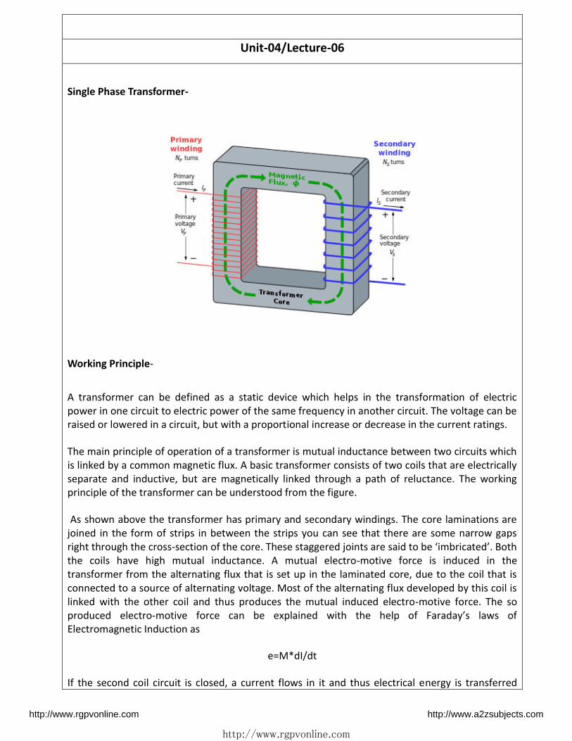
Single Phase Transformer-
Working Principle-
A transformer can be defined as a static device which helps in the transformation of electric
power in one circuit to electric power of the same frequency in another circuit. The voltage can be
raised or lowered in a circuit, but with a proportional increase or decrease in the current ratings.
The main principle of operation of a transformer is mutual inductance between two circuits which
is linked by a common magnetic flux. A basic transformer consists of two coils that are electrically
separate and inductive, but are magnetically linked through a path of reluctance. The working
principle of the transformer can be understood from the figure.
As shown above the transformer has primary and secondary windings. The core laminations are
joined in the form of strips in between the strips you can see that there are some narrow gaps
right through the cross-se tio of the o e. These stagge ed joi ts a e said to e i i ated . Both the coils have high mutual inductance. A mutual electro-motive force is induced in the
transformer from the alternating flux that is set up in the laminated core, due to the coil that is
connected to a source of alternating voltage. Most of the alternating flux developed by this coil is
linked with the other coil and thus produces the mutual induced electro-motive force. The so
produced electro- oti e fo e a e e plai ed ith the help of Fa ada s la s of Electromagnetic Induction as
e=M*dI/dt
If the second coil circuit is closed, a current flows in it and thus electrical energy is transferred
http://www.rgpvonline.com http://www.a2zsubjects.com

http://www.rgpvonline.com
magnetically from the first to the second coil.
The alternating current supply is given to the first coil and hence it can be called as the primary
winding. The energy is drawn out from the second coil and thus can be called as the secondary
winding.
In short, a transformer carries the operations shown below:
1. Transfer of electric power from one circuit to another.
2. Transfer of electric power without any change in frequency.
3. Transfer with the principle of electromagnetic induction.
4. The two electrical circuits are linked by mutual induction.
Unit-04/Lecture-07
Construction of Transformer - [RGPV June 2009]
A transformer consists following parts –
The most important parts of a transformer are the windings (coils) and the core. However for the
large capacity transformers, some other parts such as suitable tank, conservator, bushings,
breather, explosion vent etc. are also used along with the core and windings.
Laminated steel core
The material used for the construction of the transformer core is silicon steel. It is used for its high
permeability and low magnetic reluctance. Due to this the magnetic field produced in the core is
very strong. The core is in the form of stacks of laminated thin steels sheet which are electrically
isolated from each other. The laminations are typically 0.35 mm thick.
Windings of the transformer
In Figure we have shown the primary and secondary windings to be on two different limbs of the
core. But such an arrangement is made practically, then a part of the flux produced in the core will
not be linked to the secondary windings at all. This is called as the leakage flux. In order to avoid
this, the primary and secondary windings are mounted on the same limb of the core as shown in
Fig.
http://www.rgpvonline.com http://www.a2zsubjects.com

http://www.rgpvonline.com
Transformer tank
The whole assembly of large size transformer is placed in a sheet metal tank. Inside the tank the
assembly of the transformer is immersed in oil which acts as an insulator as well as a coolant.
The oil will take out the heart produced by the transformer windings and core and transformer it
to the surface of the transformer tank.
Conservator
In large transformers, some empty space is always provided above the oil level. This space is
essential for letting the oil to expand or contract due to the temperature changes.
When the oil temperature increase, it expands and the air will be expelled out from the
conservator. Whereas when the oil cools, it contracts and the outside air gets sucked inside the
conservator. This process is called as the breathing of the transformer.
However, the outside air which has being drawn in can have the moisture content. When such an
air comes in contact with the oil, the oil will absorb the moisture content and loses its insulating
properties, to some extent. This can be prevented by using a conservator.
The conservator is a cylindrical shaped air tight metal drum placed on the transformer tank. The
conservator is connected to the tank by a pipe.
The oil level in the conservator is such that, always some empty space is available above the oil.
Due to the use of conservator, the main tank will be always full with oil and the surface of oil in the
tank will not be exposed directly to the air.
Breather
The appa atus th ough hi h eathi g of the t a sfo e take pla e is alled as B eathe . The air goes in or out through the breather. To reduce the moisture content of this air, some
drying agent (material that absorbs moisture) such as silica gel or calcium chloride is used in the
breather. The dust particles present in the air are also removed by the breather.
Buccholz relay
There is a pipe connecting the tank and conservator. On this pipe a protective device called
Buccholz is mounted.
When the transformer is about to be faulty and draw large currents, the oil becomes very hot and
decomposes. During this process different types of gases are liberated. The Buccholz relay get
operated by these gases and given an alarm to the operator. If the fault continues to persist, they
the relay will trip off the main circuit breaker to protect the transformer.
S.NO RGPV QUESTIONS Year Marks
Q.4 Explain the construction and function of each parts of
transformer
June 2009 10
http://www.rgpvonline.com http://www.a2zsubjects.com

http://www.rgpvonline.com
Unit-04/Lecture-08
EMF Equation of Transformer-[RGPV June 2008] [RGPV Feb 2010]
Transformer EMF Equation
Let,
NP= Number of turns in primary coil
NS= Number of turns in secondary coil
Ømax = Maximum flux in the core in weber = Bmax. A
f = Frequency of alternating current input in hertz (HZ)
As shown in figure above, the core flux increases from its zero value to maximum value Ømax in
one quarter of the cycle , that is in ¼ frequency second.
Therefore, average rate of change of flux =Ø ax⁄ = 4f ØmaxWb/s
Now, rate of change of flux per turn means induced electro motive force in volts.
Therefore, average electro-motive force induced/turn = 4f Ømaxvolt
If flux Ø varies sinusoidally, then r.m.s value of induced e.m.f is obtained by multiplying the
average value with form factor.
Form Factor = . . . a eA e age a e = 1.11
Therefore, r.m.s value of e.m.f/turn = 1.11 X 4f Ømax= 4.44f Ømax
Now, r.m.s value of induced e.m.f in the whole of primary winding
= (induced e.m.f./turn) X Number of primary turns
Therefore,
EA = 4.44f NpØmax = 4.44fNpBmA
Similarly, r.m.s value of induced e.m.f in secondary is
EB = 4.44f NsØmax = 4.44fNsBmA
http://www.rgpvonline.com http://www.a2zsubjects.com

http://www.rgpvonline.com
In an ideal transformer on no load,
VP = EP and VS = ES , where VSis the terminal voltage
Voltage Transformation Ratio (K)
From the above equations we get
��� = � = ��� =
This constant K is known as voltage transformation ratio.
(1) If NS>NP, that is K>1 , then transformer is called step-up transformer.
(2) If NS< NP, that is K<1 , then transformer is known as step-down transformer.
Again for an ideal transformer,
Input VA = output VA ��� = �
��� = �� =
Hence, currents are in the inverse ratio of the (voltage) transformation ratio.
Types of Transformer-
1. Based on construction-
a. Core Type transformer
b. Shell Type transformer
2. Based on phases-
a. Single phase transformer
b. three phasetransformer
3. Based on operation-
a. Step Up transformer
b. Step Downtransformer
4. Based on location-
a. Power transformer
b. Distribution transformer
Q.1 A single phase transformer is connected across 200V 50 Hz supply. Number of turns in primary
is 500 while in secondary is 1000. Net cross sectional area of core is 80 cm sqr .Calculate [RGPV
Dec. 2013]
I) Transformation ratio
II) Maximum flux density in core
III) EMF induced in secondary winding
Soln-
V=200, f=50 HZ, N1=500, N2=1000, A=0.008 m2
I) K=N2/N1=1000/500=2
II) E1=4.44føN1
http://www.rgpvonline.com http://www.a2zsubjects.com

http://www.rgpvonline.com
200=4.44×50×B×0.008×500
B=0.22 wb/msqr
III) E2=4.44 f øN2
E2/E1=N2/N1
E2=400V
S.NO RGPV QUESTIONS Year Marks
Q.1 Derive EMF Equation of Transformer June 2008
Feb 2010
10
Q.2 A single phase transformer is connected across 200V 50
Hz supply. Number of turns in primary is 500 while in
secondary is 1000 . Net cross sectional area of core is 80
cm sqr .Calculate
I) Transformation ratio
II) Maximum flux density in core
III) EMF induced in secondary winding
Dec. 2013 7
http://www.rgpvonline.com http://www.a2zsubjects.com

http://www.rgpvonline.com
Unit-04/Lecture-09
Transformer Losses- Following losses occurs in a transformer[June 2013]
1. Iron Loss-
Hysteresis loss and eddy current loss both depend upon magnetic properties of the materials used
to construct the core of transformerand its design. So these losses in transformer are fixed and do
not depend upon the load current. So core losses in transformer which is alternatively known as
iron loss in transformer can be considered as constant for all range of load.
a. Eddy Current Loss-[RGPV Dec 2014]
b. Hysteresis Loss
Hysteresis loss in transformer is denoted as,
Eddy current loss in transformer is denoted as,
Where, Kh = Hysteresis constant.
Ke = Eddy current constant.
Kf = form constant.
2. Copper Loss
Copper loss is I2R loss, in primary side it is I12R1 and in secondary side it is I2
2R2 loss, where I1& I2
are primary & secondary current of transformer and R1& R2 are resistances of primary & secondary
winding. As the both primary & secondary currents depend upon load of transformer, copper loss
in transformervary with load.
Efficiency of Transformer- [RGPV Dec 2014] = � ∅ � ∅ + � + � ×
Condition for maximum efficiency-
For maximum efficiency of transformer iron loss must be equal to copper loss. �� = �
http://www.rgpvonline.com http://www.a2zsubjects.com
http://www.rgpvonline.com
All Day Efficiency-[June 2013] =Output in KWH/Input in KWH *100
Voltage Regulation- [RGPV Dec 2014]
The voltage regulation is the percentage of voltage difference between no load and full load
voltages of a transformer with respect to its full load voltage.
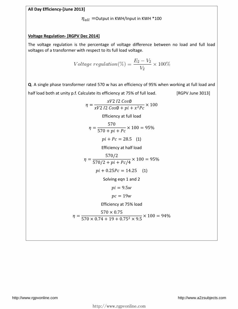
Q. A single phase transformer rated 570 w has an efficiency of 95% when working at full load and
half load both at unity p.f. Calculate its efficiency at 75% of full load. [RGPV June 3013] = � ∅ � ∅ + � + � ×
Efficiency at full load = + � + � × = % � + � = . (1)
Efficiency at half load = // + � + � / × = % � + . � = . (1)
Solving eqn 1 and 2 � = . =
Efficiency at 75% load = × .× . + + . × . × = %
http://www.rgpvonline.com http://www.a2zsubjects.com
http://www.rgpvonline.com
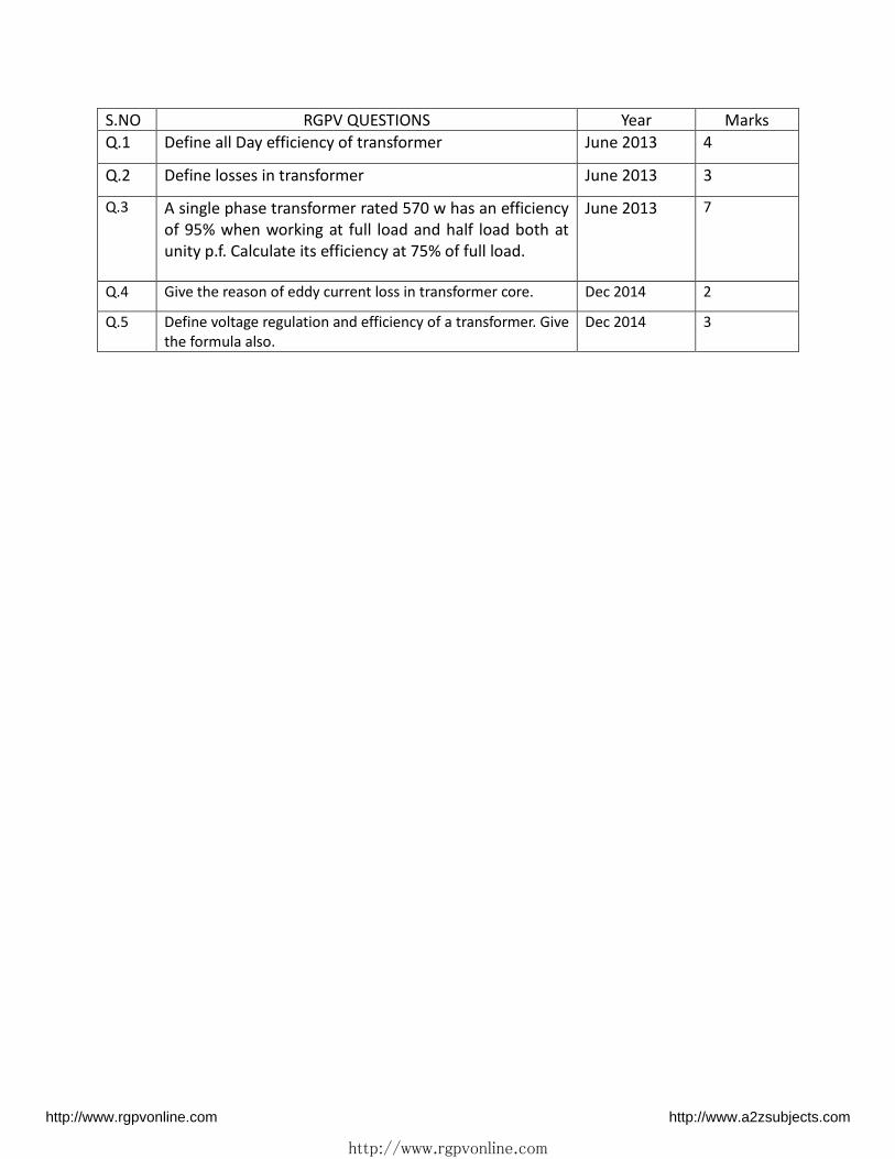
S.NO RGPV QUESTIONS Year Marks
Q.1 Define all Day efficiency of transformer June 2013 4
Q.2 Define losses in transformer June 2013 3
Q.3 A single phase transformer rated 570 w has an efficiency
of 95% when working at full load and half load both at
unity p.f. Calculate its efficiency at 75% of full load.
June 2013 7
Q.4 Give the reason of eddy current loss in transformer core. Dec 2014 2
Q.5 Define voltage regulation and efficiency of a transformer. Give
the formula also.
Dec 2014 3
http://www.rgpvonline.com http://www.a2zsubjects.com
http://www.rgpvonline.com
Unit-04/Lecture-10
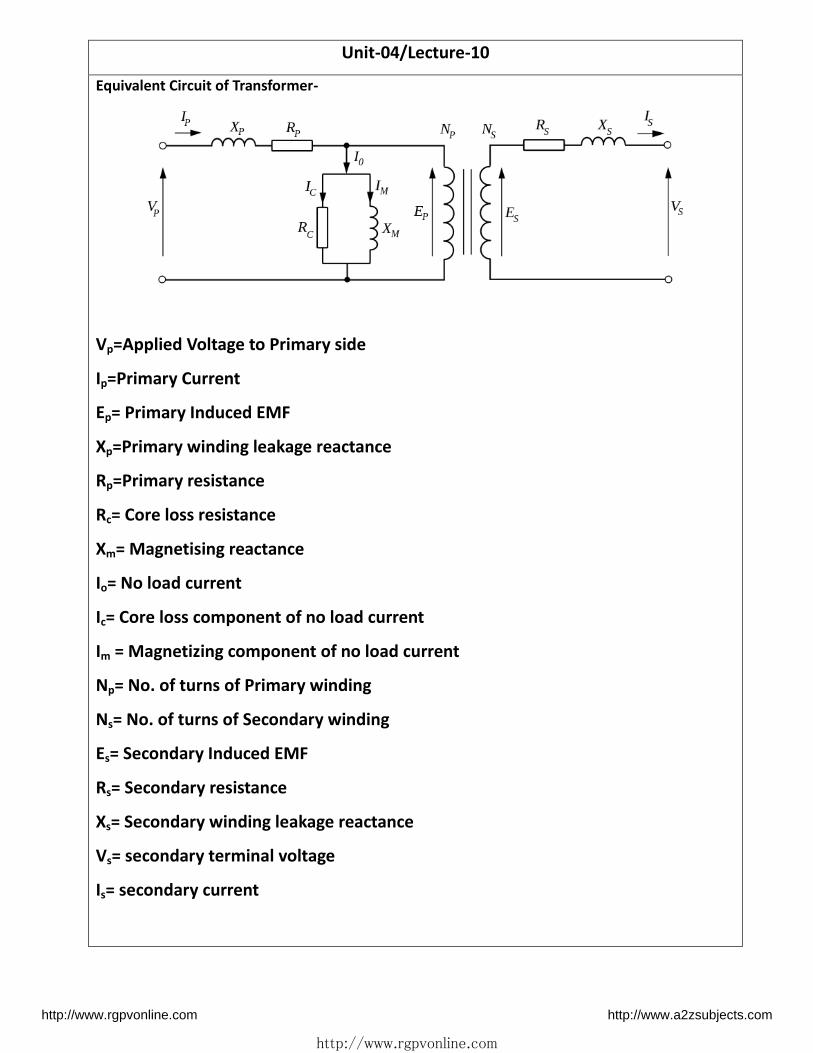
Equivalent Circuit of Transformer-
Vp=Applied Voltage to Primary side
Ip=Primary Current
Ep= Primary Induced EMF
Xp=Primary winding leakage reactance
Rp=Primary resistance
Rc= Core loss resistance
Xm= Magnetising reactance
Io= No load current
Ic= Core loss component of no load current
Im = Magnetizing component of no load current
Np= No. of turns of Primary winding
Ns= No. of turns of Secondary winding
Es= Secondary Induced EMF
Rs= Secondary resistance
Xs= Secondary winding leakage reactance
Vs= secondary terminal voltage
Is= secondary current
http://www.rgpvonline.com http://www.a2zsubjects.com

http://www.rgpvonline.com
Unit-04/Lecture-11
Testing of Transformer:
1. Open Circuit Test-
= � �� ∅� �� ∅� = �
IC = IoCos∅o
Im = IoSin∅o � = �
= ��
Zo = √ +
http://www.rgpvonline.com http://www.a2zsubjects.com

49
http://www.rgpvonline.com
Unit-04/Lecture-11
Testing of Transformer:
2. Short Circuit Test-
� � = �� �
� � = �� �
Xsc = √ −
Q. The following readings were obtained for O.C. and O.C. tests on 8KVA, 400/120V, 50 Hz
transformer. [RGPV Dec. 2010]
O.C. test (LV side) 120V, 4A, 75W
S.C.test (HV side) 9.5V, 20A, 110W
i) Find equivalent circuit par meters referred to H.V. side
ii) Efficiency at half load and 0.8 p.f. lagging
Soln- = � = . = . ℎ
= � = = . ℎ
= √ − = . ℎ
= � ∅ � ∅ + � + � ×
http://www.rgpvonline.com http://www.a2zsubjects.com

50
http://www.rgpvonline.com
= × × . × .× × . × . + + . × × = . %
S.NO RGPV QUESTIONS Year Marks
Q.1 The following readings were obtained for O.C. and O.C.
tests on 8KVA, 400/120V, 50 Hz transformer.
O.C. test (LV side) 120V, 4A, 75W
S.C.test (HV side) 9.5V, 20A, 110W
i) Find equivalent circuit par meters referred to H.V. side
ii) Efficiency at half load and 0.8 p.f. lagging
Dec. 2010 10
Q.2 The results of test performed on single phase, 20 KVA,
2200/220 volt, 50 Hz Transformer are as follows-
O.C. test (LV side) 220V, 4.2A, 148W
S.C. test (HV side) 86V, 10.5A, 360W
Determine:
The regulation and efficiency at 0.8 p.f. lagging at full
load.
Dec 2014 7
http://www.rgpvonline.com http://www.a2zsubjects.com

51
http://www.rgpvonline.com
Unit-02/Lecture-12
Phasor Diagrams of Transformer-
As load power factor is unity, the voltage V2 and I2 are in phase. Steps to draw the phasor diagram
are,
. Co side flu Φ as efe e e
2. E1 lags Φ o. Reverse E1 to get -E1.
3. E1 and E2 are inphase
4. Assume V2 in a particular direction
5. I2 is in phase with V2.
6. Add I2 R2 and I2 X2 to to get E2.
7. Reverse I2 to get I2'.
8. Add Io and I2' to get I1.
9. Add I1 R1 and to -E1 to get V1.
Angle between V1 and I1 is Φ1 a d osΦ1 is primary power factor. Remember that I1X1 leads I1
direction by 90o and I2 X2 leads I2 by 90o as current through inductance lags voltage across
inductance by 90o. The phasor diagram is shown in the Fig. below
Phasor diagram for unity power factor load
Lagging Power Factor Load[ RGPV April 2009, Dec 2014]
As load power factor is lagging osΦ2, the current I2 lags V2 a gle Φ2. So only changes in
drawing the phasor diagram is to draw I2 lagging V2 Φ2 in step 5 discussed earlier. Accordingly
direction of I2 R2, I2 X2, I2', I1, I1 R1 and I1X1 will change. Remember that whatever may be the power
factor of load, I2X2 leads I2 by 90o and I1X1 leads I1 by 90o.
The complete phasor diagram is shown in the Fig. below
http://www.rgpvonline.com http://www.a2zsubjects.com
52
http://www.rgpvonline.com
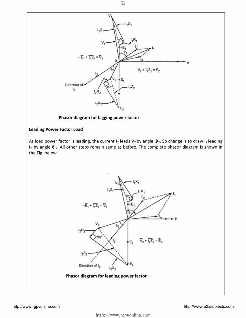
Phasor diagram for lagging power factor
Leading Power Factor Load
As load power factor is leading, the current I2 leads V2 a gle Φ2. So change is to draw I2 leading
I2 a gle Φ2. All other steps remain same as before. The complete phasor diagram is shown in
the Fig. below
Phasor diagram for leading power factor
http://www.rgpvonline.com http://www.a2zsubjects.com

53
http://www.rgpvonline.com
S.NO RGPV QUESTIONS Year Marks
Q.1 Draw the complete phasor diagram of a single phase
transformer for an inductive load. Also write the
notations used for all voltages and currents used in the
phasor diagram.
Dec 2014 3
http://www.rgpvonline.com http://www.a2zsubjects.com

54
http://www.rgpvonline.com
UNIT – 5
Electrical MACHINES
Unit-05/Lecture-01
D.C Machines- [RGPV June 2008]
D.C Machine is an electromechanical energy conversion device that converts mechanical energy
into electrical energy and vice versa. These are broadly classified into two parts say dc
generator and dc motor.
An Electric motor is a machine which converts electric energy into mechanical energy. Its action
is based on the principle that when a current-carrying conductor is placed in a magnetic field, it
experiences a mechanical force whose direction is given by Fleming s Left-hand Rule and whose
magnitude is given by F= Bil Newton.
Construction wise, there is no basic difference between a d.c. generator and a d.c. motor. In
fact, the same d.c. machine can be used interchangeably as a generator or as a motor. D.C.
motors are also like generators, shunt-wound or series-wound or compound-wound.
The same d.c.machine can be used, at least theoretically, interchangeably as a generator or as a
motor. When operating as a generator, it is driven by a mechanical machine and it develops
voltage which in turn produces a current flow in an electric circuit. When operating as a motor,
it is supplied by electric current and it develops torque which in turn produces mechanical
rotation.Commutator converts ac into dc in dc generator and dc to ac in dc motor.
http://www.rgpvonline.com http://www.a2zsubjects.com

55
http://www.rgpvonline.com
Classification of D.C. Machines-
1. DC Generator
a) Separately excited dc Generator
b) Self-excited dc Generator
i) DC Series Generator
ii) DC Shunt Generator
iii) DC Compound Generator
2. DC Motor
a) Separately excited dc Motor
b) Self-excited dc Motor
i) DC Series Motor
ii) DC Shunt Motor
iii) DC Compound Motor
EMF Equation- � = �∅���
Φ= flux/pole in weber
Z = total number of armature conductors
= No. of slots ×No. of conductors/slot
http://www.rgpvonline.com http://www.a2zsubjects.com

56
http://www.rgpvonline.com
P = No. of generator poles
A = No. of parallel paths in armature
N = armature rotation in revolutions per minute (r.p.m.)
E = e.m.f. induced in any parallel path in armature.
S.NO RGPV QUESTIONS Year Marks
Q.1 Write the principle of operation of DC motor. June 2008 10
http://www.rgpvonline.com http://www.a2zsubjects.com

57
http://www.rgpvonline.com
,.
Unit-05/Lecture-02- 03
Construction of DC Motor-[June 2008]
Sectional Diagram of a DC Machine
Figure shows a sectional view of a 4-pole D.C machine. The length of the machine is
perpendicular to the paper. Stator has got 4 numbers of projected poles with coils wound over
it. These coils may be connected in series in order that consecutive poles produce opposite
polarities (i.e., N-S-N-S) when excited from a source.
1) Yoke of DC Motor-
The magnetic frame or the yoke of dc motor made up of cast iron or steel and forms an integral
part of the stator or the static part of the motor. The outer frame or yoke serves double http://www.rgpvonline.com http://www.a2zsubjects.com

58
http://www.rgpvonline.com
purpose :
i) It provides mechanical support for the poles and acts as a protecting cover for the whole
machine.
ii) It carries the magnetic flux produced by the poles.
In small generators where cheapness rather than weight is the main consideration, yokes are
made of cast iron. But for large machines usually cast steel or rolled steel is employed.
2) Poles of DC Motor-
The magnetic poles of DC motor are structures fitted onto the inner wall of the yoke with
screws. The construction of magnetic poles basically comprises of two parts namely, the pole
core and the pole shoe stacked together under hydraulic pressure and then attached to the
yoke. These two structures are assigned for different purposes, the pole core is of small cross
sectional area and its function is to just hold the pole shoe over the yoke, whereas the pole
shoe having a relatively larger cross-sectional area spreads the flux produced over the air gap
between the stator and rotor to reduce the loss due to reluctance.
3) Field Winding of DC Motor-
The field winding of dc motor are made with field coils (copper wire) wound over the slots of
the pole shoes in such a manner that when field current flows through it, then adjacent poles
have opposite polarity are produced.When current is passed through these coils, they electro-
magnetise the poles which produce the necessary flux that is cut by revolving armature
conductors
4) Armature Core –
It houses the armature conductors or coils and causes them to rotate and hence cut the
magnetic flux of the field magnets. In addition to this, its most important function is to provide
a path of very low reluctance to the flux through the armature from a N-pole to a S-pole. It is
cylindrical or drum-shaped and is built up of usually circular sheet steel discs or laminations
approximately 0.5 mm thick.
http://www.rgpvonline.com http://www.a2zsubjects.com
59
http://www.rgpvonline.com
5) ArmatureWinding of DC Motor-
The armature winding of dc motor is attached to the rotor, or the rotating part of the machine,
and as a result is subjected to altering magnetic field in the path of its rotation which directly
esults i ag eti losses. Fo this easo the oto is ade of a atu e o e, that s ade ith
several low-hysteresis silicon steel laminations, to reduce the magnetic losses like hysteresis and
eddy current loss respectively. These laminated steel sheets are stacked together to form the
cylindrical structure of the armature core.
6) Commutator of DC Motor- [RGPV Dec 2014]
The commutator of dc motor is a cylindrical structure made up of copper segments stacked
together, but insulated from each other by mica. The function of the commutator is to facilitate
collection of current from the armature conductors; it rectified i.e. converts the alternating
current induced in the armature conductors into unidirectional current in the external load
circuit. It is of cylindrical structure and is built up of wedge-shaped segments of high-
conductivity hard-drawn or drop forged copper. The number of segments is equal to the
number of armature coils. Each commutator segment is connected to the armature conductor
by means of a copper lug or strip. As far as the dc motor is concerned, Its main function is to
commute or relay the supply current from the mains to the armature winding housed over a
rotating structure through the brushes of dc motor.
7) Brushes of DC Motor-[RGPV Dec 2014]
The brushes of dc motor whose function is to collect current from commutator are made with
carbon or graphite structures, making sliding contact over the rotating commutator. The
brushes are used to relay the electric current from external circuit to the rotating commutator
form where it flows into the armature winding. So, the commutator and brush unit of the dc
motor is concerned with transmitting the power from the static electrical circuit to the
mechanically rotating region or the rotor.The number of brushes per spindle depends on the
magnitude of the current to be collected from the commutator
S.NO RGPV QUESTIONS Year Marks
Q.1 Write the constructional details of DC motor June 2008 10
Q.2 Write the necessity and material used for the following
in a d.c. machine
i) Commutator
ii) Brush
Dec 2014 2
http://www.rgpvonline.com http://www.a2zsubjects.com

60
http://www.rgpvonline.com
Unit-05/Lecture-04
Induction Machine- [June 2009] [June 2008]
The three phase induction motor is the most widely used electrical motor. Almost 80% of the
mechanical power used by industries is provided by three phase induction motors because of
its simple and rugged construction, low cost, good operating characteristics, absence of
commutator and good speed regulation. In three phase induction motor the power is
transferred from stator to rotor winding through induction. The Induction motor is also called
asynchronous motor as it runs at a speed other than the synchronous speed.
Construction of Induction Machine-
Like any other electrical motor induction motor also have two main parts namely rotor and
stator
1. Stator: As its name indicates stator is a stationary part of induction motor. A stator
winding is placed in the stator of induction motor and the three phase supply is given to it.
2. Rotor: The rotor is a rotating part of induction motor. The rotor is connected to the
mechanical load through the shaft.
The rotor of the three phase induction motor are further classified as
1. Squirrel cage rotor,
2. Slip ring rotor or wound rotor or phase wound rotor.
Depending upon the type of rotor construction used the three phase induction motor are
classified as:
1. Squirrel cage induction motor,
2. Slip ring induction motor or wound induction motor or phase wound induction motor.
S.NO RGPV QUESTIONS Year Marks
Q.1 Explain working principle of three phase induction
motor
June 2009 10
http://www.rgpvonline.com http://www.a2zsubjects.com

61
http://www.rgpvonline.com
Unit-05/Lecture-05-06
Rotating Magnetic field in an Induction Machine- [June 2007] [June 2009][Dec. 2010]
The principle of operation of the induction machine is based on the generation of a rotating
magnetic field.A three-phase balanced winding in the stator of the Induction motor (IM) is
shown in Fig. (schematic form). In a three-phase balanced winding, the number of turns in
three windings, is equal, with the angle between the adjacent phases, say R & Y, is 1200
(electrical). Same angle of 1200 (elec.) is also between the phases, Y & B.
A three-phase balanced voltage, with the phase sequence as R-Y-B, is applied to the above
winding. In a balanced voltage, the magnitude of the voltage in each phase,
assumed to be in star in this case, is equal, with the phase angle of the voltage between
the adjacent phases, say R & Y, being 1200
The three phases of the stator winding (balanced) carry balanced alternating (sinusoidal)
currents as shown
Fig.: The relative location of the magnetic axis of three phases
Let the maximum value of flux due to any one of the three phases be Φm. The resultant flux
Φr, at any instant, is given by the vector sum of the individual fluxes, ΦA, ΦBand ΦCdue to
three phases.
The resultant is 1.5Φm and has rotated clockwise through an additional angle 60º or through
an angle of 1800 from the start.
http://www.rgpvonline.com http://www.a2zsubjects.com

62
http://www.rgpvonline.com
Hence, the resultant flux is of constant value = 1.5 Φm i.e. 1.5 times the maximum value of the
flux due to any phase. The resultant flux rotates around the stator at synchronous speed given
by Ns = 120 f/P.
Principle of operation of Induction motor:
The balanced three-phase winding of the stator is supplied with a balanced three phase voltage.
The current inthe stator winding produces a rotating magnetic field, the magnitudeof which
remains constant. The axis of the magnetic field rotates at a synchronous speed, a function of
the supply frequency (f), and number of poles (p) in the stator winding. The magnetic flux lines
in the air gap cut both stator and rotor (being stationary, as the motor speed is zero) conductors
at the same speed. The emfs in both stator and rotor conductors are induced at the same
frequency, i.e. line or supply frequency, with No. of poles for both stator and rotor windings
(assuming wound one) being same. The stator conductors are always stationary, with the
frequency in the stator winding being same as line frequency. As the rotor winding is short-
circuited at the slip-rings, current flows in the rotor windings. The electromagnetic torque in the
motor is in the same direction as that of the rotating magnetic field, due to the interaction
between the rotating flux produced in the air gap by the current in the stator winding, and the
u e t i the oto i di g. This is as pe Le z s la , as the de eloped to ue is i su h direction that it will oppose the cause, which results in the current flowing in the rotor winding.
This is i espe ti e of the oto t pe used − age o ound one, with the cage rotor, with the bars
short-circuited by two end-rings, is considered equivalent to a wound one The current in the
rotor bars interacts with the air-gap flux to develop the torque, irrespective of the no. of poles
for which the winding in the stator is designed. Thus, the cage rotor may be termed as universal
one.
The induced emf and the current in the rotor are due to the relative velocity between the rotor
conductors and the rotating flux in the air-gap, which is maximum, when the rotor is stationary.
As the rotor starts rotating in the same direction, as that of the rotating magnetic field due to
production of the torque as stated earlier, the relative velocity decreases, along with lower
values ofinduced emf and current in the rotor. If the rotor speed is equal that of the rotating
magnetic field, which is termed as synchronous speed, and also in the same direction, the
relative velocity is zero, which causes both the induced emf and current in the rotor to be
reduced to zero. Under this condition, torque will notbe produced. So, for production of
positive (motoring) torque, the rotor speed must always be lower than the synchronous speed.
The rotor speed is never equal to the synchronous speed in an IM.
http://www.rgpvonline.com http://www.a2zsubjects.com

63
http://www.rgpvonline.com
S.NO RGPV QUESTIONS Year Marks
Q.1 Explain rotating magnetic field in a three phase
induction motor
June 2009
June 2007
10
Q.2 Derive the e.m.f. equation of a 3 phase Induction motor. Dec 2014 7
Unit-05/Lecture-07
Synchronous Machine-[RGPV Dec 2014]
A synchronous electric motor is an AC motor in which, at steady state, the rotation of the shaft
is synchronized with the frequency of the supply current; the rotation period is exactly equal to
an integral number of AC cycles. Synchronous motors contain electromagnets on the stator of
the motor that create a magnetic field which rotates in time with the oscillations of the line
current. The rotor turns in step with this field, at the same rate. The synchronous motor and
induction motor are the most widely used types of AC motor. The difference between the two
types is that the synchronous motor rotates in exact synchronism with the line frequency.
Some characteristic features of a synchronous motor are
i) It runs either at synchronous speedor not at all i.e.while running it maintains a constant
speed. The only way tochange its speed is to vary the supplyfrequency.
ii) It is not inherently self-starting. It has to be run up to synchronous (or near
synchronous) speed by some means, before it can be synchronized to thesupply.
iii) It is capable of being operated undera wide range of power factors, both lagging and
leading. Hence, it can be usedfor power correction purposes, in addition to supplying
torque to drive loads.
Construction of Synchronous Machine-
Stator-
The exterior frame, made of steel, either cast or a weldment, supports the laminated stator
core and has feet, or flanges, for mounting to the foundation. Frame vibration from core
magnetic forcing or rotor unbalance is minimized by resilient mounting the core anor by
designing to avoid frame resonance with forcing frequencies. If bracket type bearings are
employed, the frame must support the bearings, oil seals, and gas seals when cooled with
hydrogen or gas other than air.
http://www.rgpvonline.com http://www.a2zsubjects.com

64
http://www.rgpvonline.com
Rotor-
Synchronous rotors are designed primarily for applications requiring highly efficient motors.
Each pole assembly is made from high strength steel laminations with a DC field winding
encircling the pole body. The field winding consists of a rectangular section of insulated copper
wire wound directly on an insulated pole body and bonded by a high temperature, high
strength insulating epoxy resin.
EMF Equation-
E=√ × � × � ×
Q) Calculate the no load terminal voltage of a 3- phase 4 pole star connected alternator running
at 1500rpm having the following data:[RGPV Feb. 2010]
Sinusoidally distributed two per pole=66mwb,
Total no of armature slots=72
No.of conductors per slot=10
Distribution factor =0.96
Assume full pitch winding.
Soln-
P=4
Ns=1500 ∅ = × −
Kd=0.96
Conductor per slot=10
Total no. Of conductors=72× =
Ns=120f/P
1500=120f/4
F=50 Hz
N=720/2 � = √ × � × × ∅ × � × � = √ × . × × × − × × . � = .
S.NO RGPV QUESTIONS Year Marks
Q.1 Q) Calculate the no load terminal voltage of a 3- phase 4
pole star connected alternator running at 1500rpm
having the following data:
Sinusoidally distributed two per pole=66mwb,
Total no of armature slots=72
No.of conductors per slot=10
Distribution factor =0.96
Assume full pitch winding.
Feb. 2010 7
Q.2 Why synchronous machine is called as synchronous.
Define synchronous speed.
Dec 2014 2
http://www.rgpvonline.com http://www.a2zsubjects.com
65
http://www.rgpvonline.com
Unit-05/Lecture-08
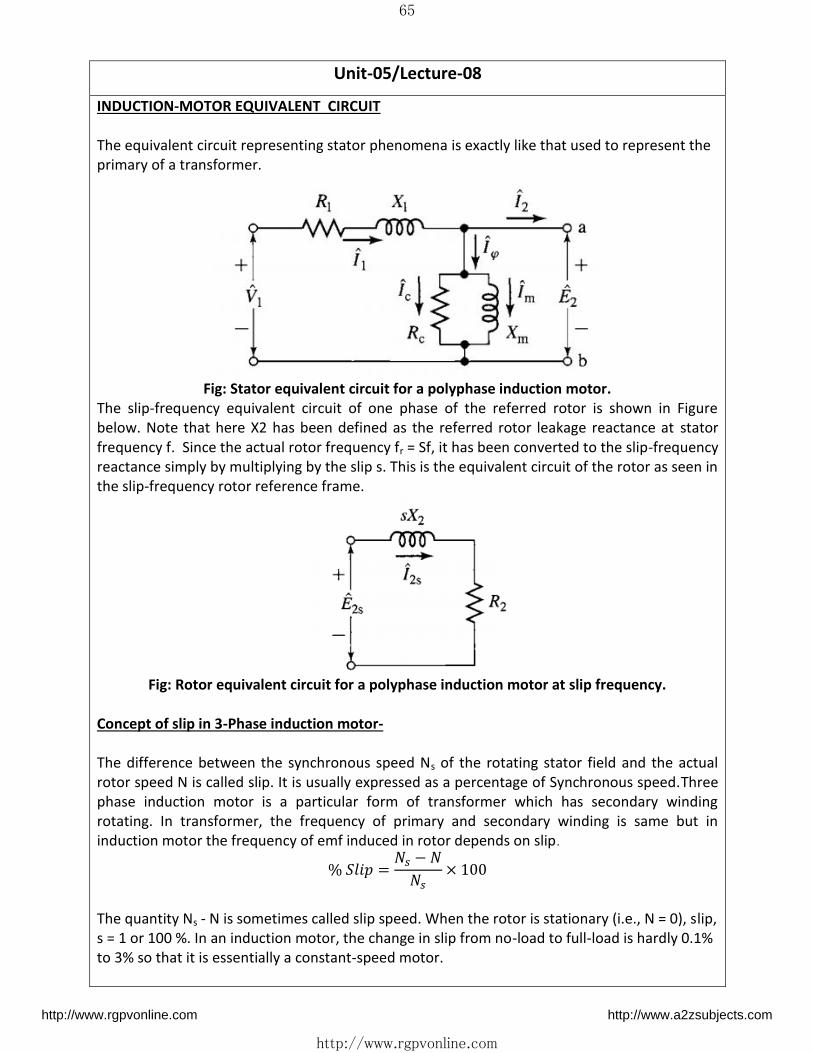
INDUCTION-MOTOR EQUIVALENT CIRCUIT
The equivalent circuit representing stator phenomena is exactly like that used to represent the
primary of a transformer.
Fig: Stator equivalent circuit for a polyphase induction motor.
The slip-frequency equivalent circuit of one phase of the referred rotor is shown in Figure
below. Note that here X2 has been defined as the referred rotor leakage reactance at stator
frequency f. Since the actual rotor frequency fr = Sf, it has been converted to the slip-frequency
reactance simply by multiplying by the slip s. This is the equivalent circuit of the rotor as seen in
the slip-frequency rotor reference frame.
Fig: Rotor equivalent circuit for a polyphase induction motor at slip frequency.
Concept of slip in 3-Phase induction motor-
The difference between the synchronous speed Ns of the rotating stator field and the actual
rotor speed N is called slip. It is usually expressed as a percentage of Synchronous speed.Three
phase induction motor is a particular form of transformer which has secondary winding
rotating. In transformer, the frequency of primary and secondary winding is same but in
induction motor the frequency of emf induced in rotor depends on slip. % � = � − �� ×
The quantity Ns - N is sometimes called slip speed. When the rotor is stationary (i.e., N = 0), slip,
s = 1 or 100 %. In an induction motor, the change in slip from no-load to full-load is hardly 0.1%
to 3% so that it is essentially a constant-speed motor.
http://www.rgpvonline.com http://www.a2zsubjects.com

66
http://www.rgpvonline.com
Unit-05/Lecture-09
Torque-Slip Characteristics-[RGPV Dec 2014]
If a curve is drawn between the torque and slip for a particular value of rotorresistance R2, the
graph thus obtained is called torque-slip characteristic.
= ∅ �+
The torque-slip or torque-speed characteristic, as per the equation of torque, is shown in Figure
below. The slip is = − = −
The range of speed is between 0.0 (standstill) and (synchronous speed). The range of slip is
between 0.0 ( = ) and 1.0 ( = )
It may be observed from the torque-slip characteristic (Fig. 32.1), or described earlier, that the
output torque developed increases, if the slip increases from 0.0 to , or the motor speed
decreases from to This ensures stable operation of IM in this region (0.0 < s < ), for
constant load torque. But the output torque developed decreases, if the slip increases
from to 1.0, or the motor speed decreases from to zero (0.0). This results in unstable
operation of IM in this region ( < s <1.0 ), for constant load torque. However, for fan type
loads with the torque as ( ), stable operation of IM is achieved in this region ( < s < 1.0)
http://www.rgpvonline.com http://www.a2zsubjects.com
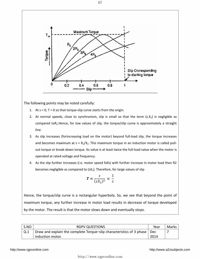
67
http://www.rgpvonline.com
The following points may be noted carefully:
1. At s = 0, T = 0 so that torque-slip curve starts from the origin.
2. At normal speeds, close to synchronism, slip is small so that the term (s.X2) is negligible as
compared toR2.Hence, for low values of slip, the torque/slip curve is approximately a straight
line.
3. As slip increases (forincreasing load on the motor) beyond full-load slip, the torque increases
and becomes maximum at s = R2/X2. This maximum torque in an induction motor is called pull-
out torque or break-down torque. Its value is at least twice the full-load value when the motor is
operated at rated voltage and frequency.
4. As the slip further increases (i.e. motor speed falls) with further increase in motor load then R2
becomes negligible as compared to (sX2). Therefore, for large values of slip � ∝ ∝
Hence, the torque/slip curve is a rectangular hyperbola. So, we see that beyond the point of
maximum torque, any further increase in motor load results in decrease of torque developed
by the motor. The result is that the motor slows down and eventually stops.
S.NO RGPV QUESTIONS Year Marks
Q.1 Draw and explain the complete Torque–slip characteristics of 3 phase
induction motor.
Dec
2014
7
http://www.rgpvonline.com http://www.a2zsubjects.com
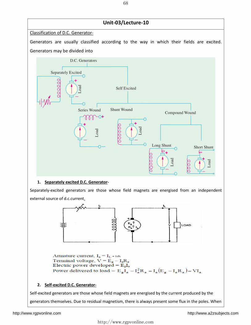
68
http://www.rgpvonline.com
Unit-03/Lecture-10
Classification of D.C. Generator-
Generators are usually classified according to the way in which their fields are excited.
Generators may be divided into
1. Separately excited D.C. Generator-
Separately-excited generators are those whose field magnets are energised from an independent
external source of d.c.current.
2. Self-excited D.C. Generator-
Self-excited generators are those whose field magnets are energised by the current produced by the
generators themselves. Due to residual magnetism, there is always present some flux in the poles. When
http://www.rgpvonline.com http://www.a2zsubjects.com

69
http://www.rgpvonline.com
the armature is rotated, some e.m.f. and hence some induced current is produced which is partly or fully
passed through the field coils thereby strengthening the residual pole flux. There are three types of self-
excited generators named according to the manner in which their field coils (or windings) are connected
to the armature
i) D.C. Series Generator –In this case, the field windings are joined in series with the armature
conductors.
ii) D.C. Shunt Generator –The field windings are connected across or in parallel with the armature
conductors and have the full voltage of the generator applied across them
http://www.rgpvonline.com http://www.a2zsubjects.com

70
http://www.rgpvonline.com
Unit-05/Lecture-11
iii) D.C. Compound Generator –
It is a combination of a few series and a few shunt windings and can be either short-shunt. In a
compound generator, the shunt field is stronger than the series field. When series field aids the shunt
field, generator is said to be commutatively-compounded. On the other hand if series field opposes the
shunt field, the generator is said to be differentially compounded.
or long-shunt
Armature current, � = �� + � ℎ
Terminal Voltage, = � − � − �
Classification of D.C. Motor- 1) Separately excited D.C. Motor-
2)Self excited D.C.Motor-[RGPV Dec 2014] i) D.C. Series Motor –
Armature current, � = ��
Terminal Voltage, = � + �
http://www.rgpvonline.com http://www.a2zsubjects.com

71
http://www.rgpvonline.com
Unit-05/Lecture-12
Q. A 4 pole wave connected D.C generator has 900 armature conductors and flux per pole of
0.04wb. At what speed it must be run to generate 500 V. [RGPV Dec. 2010]
Soln- � = ∅ = . = � =
For wave winding
A=2 � = �∅��� = × . × � × / × � =
Q. A 4 pole d.c. shunt generator with a lap o wound armature having 390 conductors has to
supplya load of 500 lamps each of 100w at 250v,Allowing 10v for the voltage drop in the
connecting leads between the generator and the load and brush drop of 2v calculate the speed
at which the generator should be driven .∅ =30mwb,Ra=0.05ohm Rsh=65ohm.
Soln- [RGPV Feb 2010]
V=250V
Lamp load
Load Power=500*100 = kW �� = �� = = � ℎ = ℎ = + =
Ia=Il+Ish = 200+4 = 204A
Eg=V+Iara+Vb+Vload
Eg=250+204×0.05+2+10=272.72Volts � = �∅��� � = . × × / × × − × � =
S.NO RGPV QUESTIONS Year Marks
Q.1 What do you mean by separately excited and self-
excited generator, Sketch following
Shunt Wound, Series Wound, Compound wound
Dec 2013 7
Q.2 A 4 pole wave connected D.C generator has 900
armature conductors and flux per pole of 0.04wb. At
what speed it must be run to generate 500 V
Dec. 2010 7
http://www.rgpvonline.com http://www.a2zsubjects.com
72
http://www.rgpvonline.com
Q.3 A 4 pole d.c. shunt generator with a lap o wound
armature having 390 conductors has to supply a load of
500 lamps each of 100w at 250v,Allowing 10v for the
voltage drop in the connecting leads between the
generator and the load and brush drop of 2v calculate
the speed at which the generator should be driven
.∅ =30mwb,Ra=0.05ohm Rsh=65ohm.
Feb 2010 10
Q.4 Classify self excited D.C. motor. Dec 2014 3
Unit-05/Lecture-13
Losses in a Electrical Machine 1) Copper losses- These losses are the losses due to armature and field copper
windings. Thus copper losses consists of Armature copper loss, Field copper loss
and loss due to brush contact resistance
a) Armature Cu loss- Armature copper loss = Ia2Ra (Where Ia is Armature current and Ra is
Armature resistance)
This loss is about 30 to 40% of full load losses.
b) Field Cu loss- Field copper loss = If2Rf (where If is field current and Rf is field resistance)
In case of shunt wounded field, this loss is practically constant.
Field copper loss is about 20 to 30% of full load losses.
c) Loss due to brush contact resistance- Brush contact resistance also contributes to this type of
loss. Generally this loss is included into armature copper loss.
2) Iron Losses- As iron core of the armature is continuously rotating in a
magnetic field, there are some losses taking place in the core. Therefore
iron losses are also known as Core losses. This loss consists of Hysteresis
loss and Eddy current loss.
a) Hysteresis loss- Hysteresis loss is due to reversal of magnetization of the armature core.
When the core passes under one pair of poles, it undergoes one complete cycle of
magnetic reversal.
b) Eddy current loss- When the armature core rotates in the magnetic field, an emf is also
induced in the core (just like it induces in armature conductors), according to the
Faraday's law of electromagnetic induction. Though this induced emf is small, it causes a
large current to flow in the body due to low resistance of the core. This current is known
as eddy current. The power loss due to this current is known as eddy current loss.
http://www.rgpvonline.com http://www.a2zsubjects.com

73
http://www.rgpvonline.com
3) Mechanical losses- Mechanical losses consist of the losses due to friction
in bearings and commutator. Air friction loss of rotating armature also
contributes.
These losses are about 10 to 20% of full load losses. a) Friction losses
b) Windage losses
http://www.rgpvonline.com http://www.a2zsubjects.com