UNIT PLAN Exemplary - ricreport.orgricreport.org/spa/Technology Education...
44
UNIT PLAN Exemplary
Transcript of UNIT PLAN Exemplary - ricreport.orgricreport.org/spa/Technology Education...

UNIT PLAN
Exemplary
Exit Portfolio.Implemented Unit Plan Scoring Rubric.doc 2/23/2011
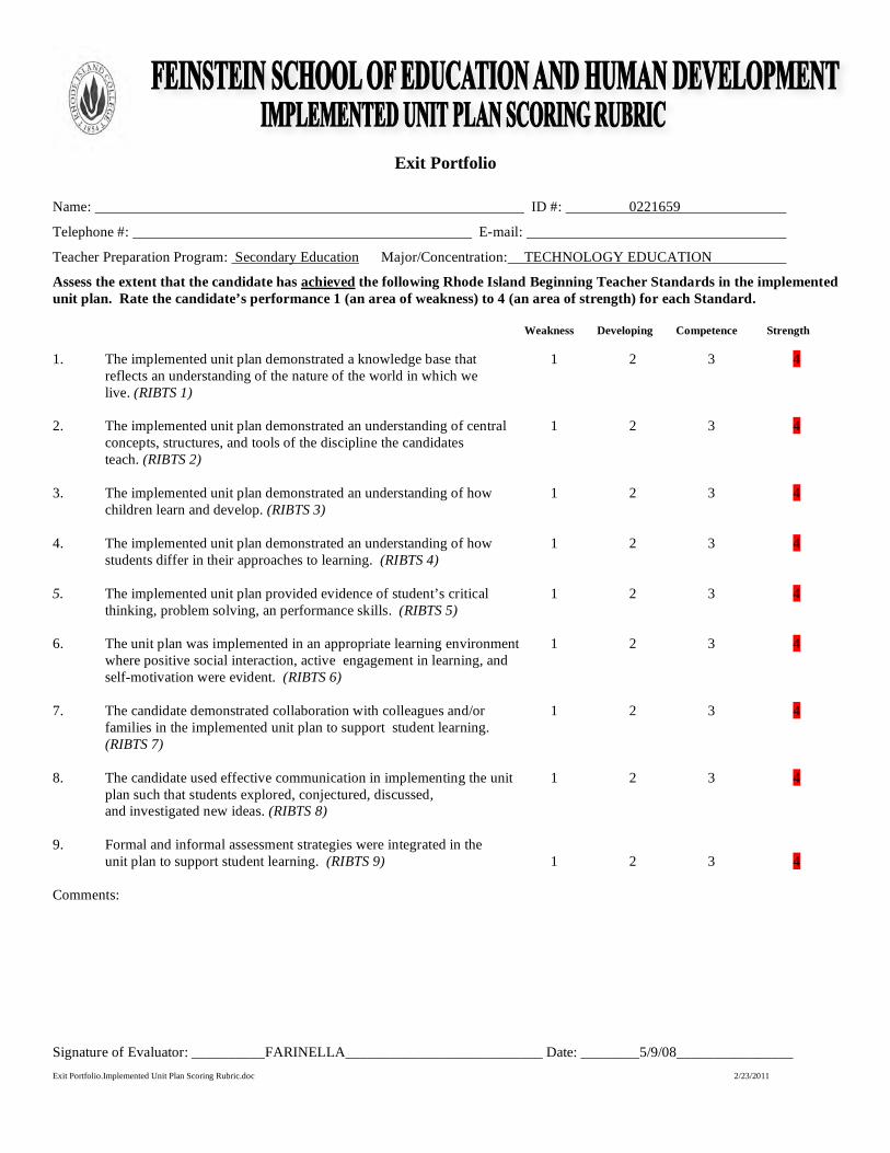
Exit Portfolio
Name: ID #: 0221659
Telephone #: E-mail:
Teacher Preparation Program: Secondary Education Major/Concentration: TECHNOLOGY EDUCATION
Assess the extent that the candidate has achieved the following Rhode Island Beginning Teacher Standards in the implemented unit plan. Rate the candidate’s performance 1 (an area of weakness) to 4 (an area of strength) for each Standard.
Weakness Developing Competence Strength
1. The implemented unit plan demonstrated a knowledge base that 1 2 3 4reflects an understanding of the nature of the world in which we live. (RIBTS 1)
2. The implemented unit plan demonstrated an understanding of central 1 2 3 4concepts, structures, and tools of the discipline the candidates teach. (RIBTS 2)
3. The implemented unit plan demonstrated an understanding of how 1 2 3 4
children learn and develop. (RIBTS 3)
4. The implemented unit plan demonstrated an understanding of how 1 2 3 4students differ in their approaches to learning. (RIBTS 4)
5. The implemented unit plan provided evidence of student’s critical 1 2 3 4thinking, problem solving, an performance skills. (RIBTS 5)
6. The unit plan was implemented in an appropriate learning environment 1 2 3 4where positive social interaction, active engagement in learning, andself-motivation were evident. (RIBTS 6)
7. The candidate demonstrated collaboration with colleagues and/or 1 2 3 4families in the implemented unit plan to support student learning. (RIBTS 7)
8. The candidate used effective communication in implementing the unit 1 2 3 4plan such that students explored, conjectured, discussed, and investigated new ideas. (RIBTS 8)
9. Formal and informal assessment strategies were integrated in the unit plan to support student learning. (RIBTS 9) 1 2 3 4
Comments:
Signature of Evaluator: __________FARINELLA___________________________ Date: ________5/9/08________________
Exit Portfolio.Implemented Unit Plan Scoring Rubric.doc 2/23/2011
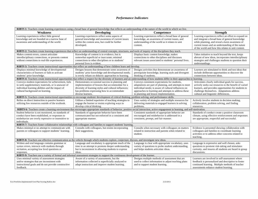
Performance Indicators
RIBTS 1: Teachers create learning experiences using a broad base of general knowledge that reflects an understanding of the nature of the world in which we live. Weakness Developing Competence Strength
Learning experiences reflect little general knowledge and are founded on a narrow base of awareness and understanding of the world.
Learning experiences reflect some aspects of general knowledge and awareness of current issues within the content area, but could be further developed.
Learning experiences reflect a broad base of general knowledge, an awareness of current issues, and understanding of the world as it relates to unit content.
Learning experiences reflect an effort to expand on and integrate a broad base of general knowledge while planning, and reveal a keen awareness of current issues and an understanding of the nature of the world and how this relates to unit content.
RIBTS 2: Teachers create learning experiences that reflect an understanding of central concepts, structures, and tools of inquiry of the disciplines they teach. Makes content errors, cannot articulate interdisciplinary connections, or presents content without connections to real-life experiences.
Knowledge of content is in evidence, but is somewhat superficial or inaccurate; minimal connections to other disciplines or to students’ personal lives is evident.
Displays basic content knowledge, makes connections to other disciplines and discusses relevant issues associated to students’ personal lives.
Takes initiative to teach beyond the text, keeps abreast of new ideas, incorporates interdisciplinary strategies and challenges students to question their understandings.
RIBTS 3: Teachers create instructional opportunities that reflect an understanding of how children learn and develop. Displays minimal knowledge of developmental characteristics of learners or fails to activate students’ prior knowledge.
Designs lessons that demonstrate some awareness of students’ prior knowledge and developmental needs; is overly reliant on didactic approaches to learning.
Designs activities that demonstrate an awareness of prerequisite knowledge, learning style and divergent thinking of students.
Learners are stimulated to think and test ideas that include deliberate opportunities to discover the connections between ideas.
RIBTS 4: Teachers create instructional opportunities that reflect a respect for the diversity of learners and an understanding of how students differ in their approaches to learning. Conveys modest expectations for achievement, fails to seek supplementary materials, or is unaware of individual learning abilities and the impact of cultural background on learning.
Demonstrates occasional success in planning and implementation of lessons that accommodate for a diversity of learning styles and cultural influences; has problems expressing how to accommodate diverse learners.
Conveys consistent expectations for students, adaptations are part of planning, and attempts to meet individual needs; is aware of cultural influences on approaches to learning and attempts to address these in planning and lesson implementation.
Articulates clearly individual goals for success, actively seeks out resources to the benefit of varied learners, and provides opportunities for students to challenge themselves. Adaptations address cultural and linguistic differences.
RIBTS 5: Teachers create instructional opportunities to encourage students' development of critical thinking, problem solving, and performance skills. Relies on direct instruction to passive learners utilizing few resources outside of the textbook.
Utilizes a limited repertoire of teaching strategies to engage the learner or resists exploring ways to develop critical thinking.
Uses variety of strategies and multiple resources for delivering materials to engaged learners in solving problems.
Actively involve students in decision making, collaboration, problem solving, and finding resources.
RIBTS 6: Teachers create a learning environment that encourages appropriate standards of behavior, positive social interaction, active engagement in learning, and self-motivation. Student behavior is not monitored, no standards of conduct have been established, or responses to misbehavior are overly repressive or insensitive to individuals.
Standards of appropriate behavior have been communicated but not enforced in a consistent and appropriate manner.
Consistent standards of appropriate behavior are encouraged and misbehavior is addressed in a consistent, prompt, and fair manner.
Standards of conduct create a positive classroom climate, using effective reinforcement and responses are appropriate, respectful and successful.
RIBTS 7: Teachers foster collaborative relationships with colleagues and families to support students' learning. Makes minimal or no attempt to communicate with parents or colleagues to support students’ learning.
Consults with colleagues, but resists incorporating their suggestions.
Consults when necessary with colleagues on matters related to instruction and parents when related to student.
Evidence is presented showing collaboration with colleagues and families to coordinate learning activities or to address other concerns related to teaching.
RIBTS 8: Teachers use effective communication as the vehicle through which students explore, conjecture, discuss, and investigate new ideas. Written and oral language contains grammar or syntax errors, interacts with students through recitation, accepting low level questions or responses.
Language and vocabulary is appropriate much of the time in an attempt to promote deeper understanding but is inconsistent in allowing students to express ideas.
Language is clear with appropriate vocabulary, uses variety of questions to probe student understanding, and helps students articulate ideas.
Language is expressive and well chosen, asks questions to promote risk-taking and stimulates curiosity, and insures all students are heard in group discussions.
RIBTS 9: Teachers use a variety of formal and informal assessment strategies to support the continuous development of the learner. Uses minimal variety of assessment strategies and/or strategies that are inconsistent with instructional goals and do not provide constructive feedback.
Aware of a variety of assessments, but the information collected is superficially analyzed to adapt instruction and improve student learning.
Designs multiple methods of assessment that are used to collect information to adjust teaching plans and to support student learning.
Learners are involved in self-assessment where feedback is personalized and descriptive to foster continued learning. Multiple methods of teacher assessments enhance student learning.
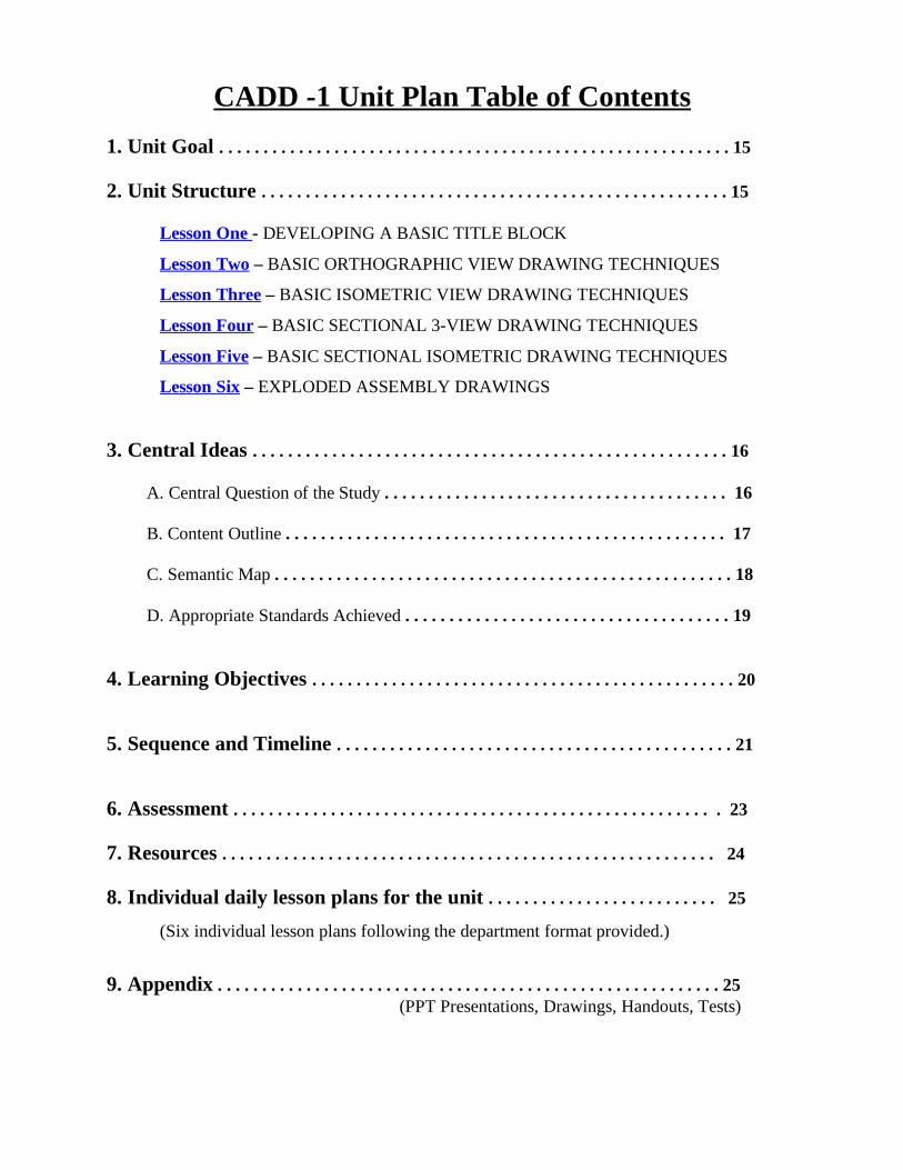
CADD -1 Unit Plan Table of Contents 1. Unit Goal . . . . . . . . . . . . . . . . . . . . . . . . . . . . . . . . . . . . . . . . . . . . . . . . . . . . . . . . . . 15 2. Unit Structure . . . . . . . . . . . . . . . . . . . . . . . . . . . . . . . . . . . . . . . . . . . . . . . . . . . . . 15
Lesson One - DEVELOPING A BASIC TITLE BLOCK
Lesson Two – BASIC ORTHOGRAPHIC VIEW DRAWING TECHNIQUES
Lesson Three – BASIC ISOMETRIC VIEW DRAWING TECHNIQUES
Lesson Four – BASIC SECTIONAL 3-VIEW DRAWING TECHNIQUES
Lesson Five – BASIC SECTIONAL ISOMETRIC DRAWING TECHNIQUES
Lesson Six – EXPLODED ASSEMBLY DRAWINGS
3. Central Ideas . . . . . . . . . . . . . . . . . . . . . . . . . . . . . . . . . . . . . . . . . . . . . . . . . . . . . . 16
A. Central Question of the Study . . . . . . . . . . . . . . . . . . . . . . . . . . . . . . . . . . . . . . . 16 B. Content Outline . . . . . . . . . . . . . . . . . . . . . . . . . . . . . . . . . . . . . . . . . . . . . . . . . . 17 C. Semantic Map . . . . . . . . . . . . . . . . . . . . . . . . . . . . . . . . . . . . . . . . . . . . . . . . . . . . 18 D. Appropriate Standards Achieved . . . . . . . . . . . . . . . . . . . . . . . . . . . . . . . . . . . . . 19
4. Learning Objectives . . . . . . . . . . . . . . . . . . . . . . . . . . . . . . . . . . . . . . . . . . . . . . . . 20 5. Sequence and Timeline . . . . . . . . . . . . . . . . . . . . . . . . . . . . . . . . . . . . . . . . . . . . . 21 6. Assessment . . . . . . . . . . . . . . . . . . . . . . . . . . . . . . . . . . . . . . . . . . . . . . . . . . . . . . . 23 7. Resources . . . . . . . . . . . . . . . . . . . . . . . . . . . . . . . . . . . . . . . . . . . . . . . . . . . . . . . . 24 8. Individual daily lesson plans for the unit . . . . . . . . . . . . . . . . . . . . . . . . . . 25
(Six individual lesson plans following the department format provided.)
9. Appendix . . . . . . . . . . . . . . . . . . . . . . . . . . . . . . . . . . . . . . . . . . . . . . . . . . . . . . . . . 25
(PPT Presentations, Drawings, Handouts, Tests)
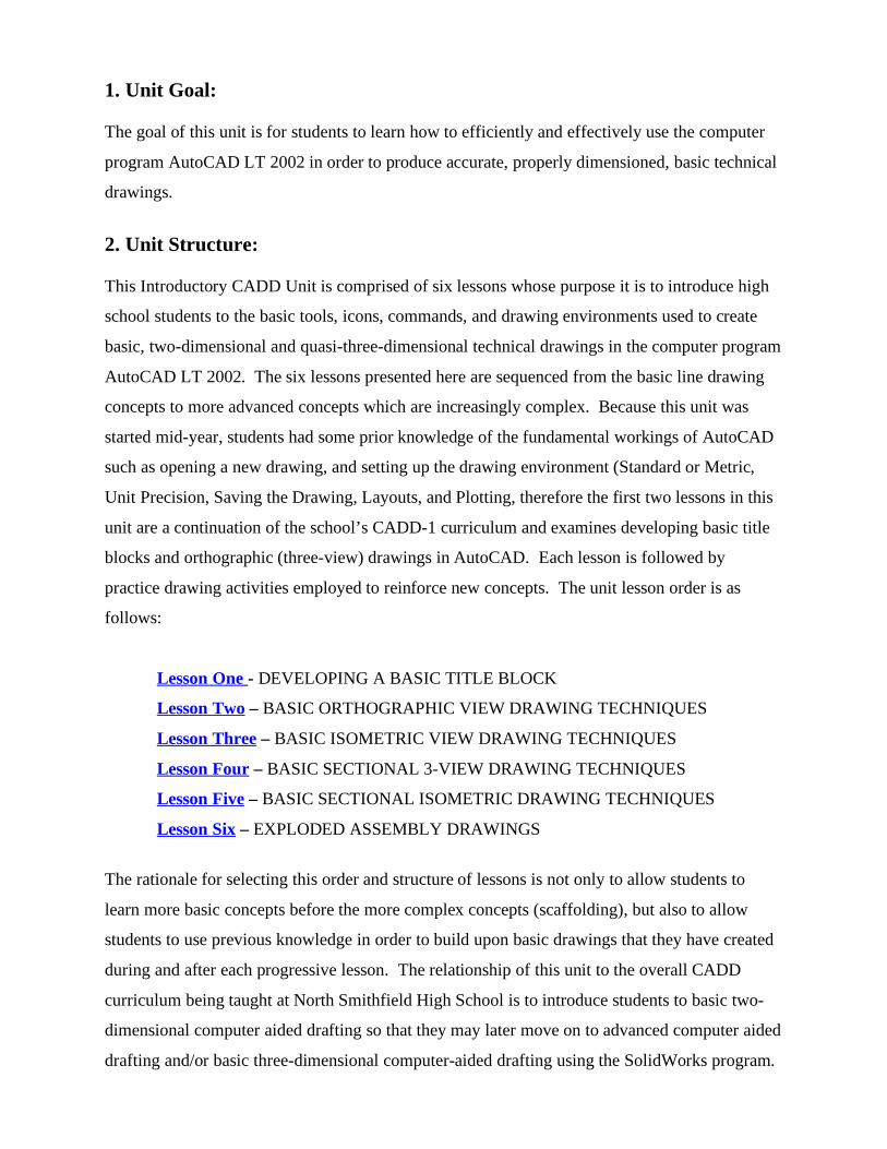
1. Unit Goal:
The goal of this unit is for students to learn how to efficiently and effectively use the computer
program AutoCAD LT 2002 in order to produce accurate, properly dimensioned, basic technical
drawings.
2. Unit Structure:
This Introductory CADD Unit is comprised of six lessons whose purpose it is to introduce high
school students to the basic tools, icons, commands, and drawing environments used to create
basic, two-dimensional and quasi-three-dimensional technical drawings in the computer program
AutoCAD LT 2002. The six lessons presented here are sequenced from the basic line drawing
concepts to more advanced concepts which are increasingly complex. Because this unit was
started mid-year, students had some prior knowledge of the fundamental workings of AutoCAD
such as opening a new drawing, and setting up the drawing environment (Standard or Metric,
Unit Precision, Saving the Drawing, Layouts, and Plotting, therefore the first two lessons in this
unit are a continuation of the school’s CADD-1 curriculum and examines developing basic title
blocks and orthographic (three-view) drawings in AutoCAD. Each lesson is followed by
practice drawing activities employed to reinforce new concepts. The unit lesson order is as
follows:
Lesson One - DEVELOPING A BASIC TITLE BLOCK
Lesson Two – BASIC ORTHOGRAPHIC VIEW DRAWING TECHNIQUES
Lesson Three – BASIC ISOMETRIC VIEW DRAWING TECHNIQUES
Lesson Four – BASIC SECTIONAL 3-VIEW DRAWING TECHNIQUES
Lesson Five – BASIC SECTIONAL ISOMETRIC DRAWING TECHNIQUES
Lesson Six – EXPLODED ASSEMBLY DRAWINGS
The rationale for selecting this order and structure of lessons is not only to allow students to
learn more basic concepts before the more complex concepts (scaffolding), but also to allow
students to use previous knowledge in order to build upon basic drawings that they have created
during and after each progressive lesson. The relationship of this unit to the overall CADD
curriculum being taught at North Smithfield High School is to introduce students to basic two-
dimensional computer aided drafting so that they may later move on to advanced computer aided
drafting and/or basic three-dimensional computer-aided drafting using the SolidWorks program.
3. Central Ideas:
At the end of this unit, students will be able to recognize the advantages of Computer Aided
Drafting and Design over traditional hand drafting, and they will be able to create, dimension,
layout, and plot basic two-dimensional and quasi-three-dimensional technical drawings using the
computer program AutoCAD LT 2002. The common theme that ties this unit together is the
sequential use of the basic tools, icons, and commands which build upon each other in a
progressive manner in order to create said drawings.
A. Central Question:
What tools and techniques can be employed using the computer program AutoCAD LT 2002 in
order to create basic technical drawings more effectively and efficiently than traditional hand
drawing?
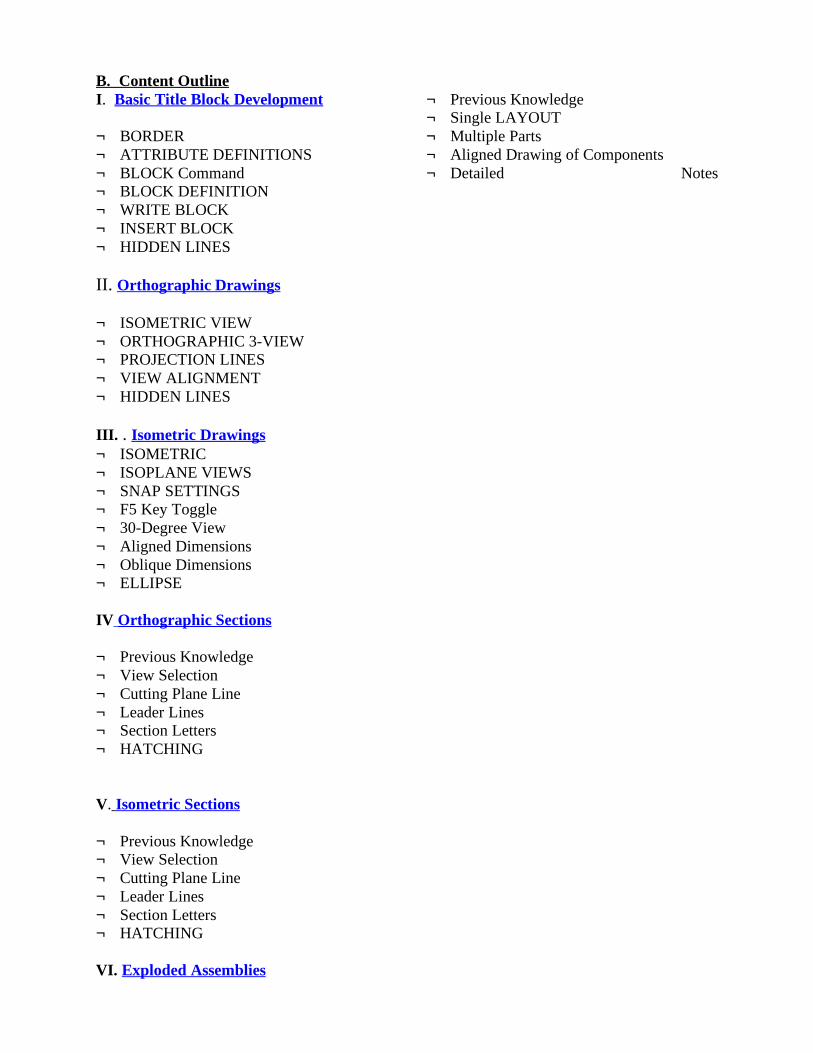
B. Content Outline I. Basic Title Block Development ¬ BORDER ¬ ATTRIBUTE DEFINITIONS ¬ BLOCK Command ¬ BLOCK DEFINITION ¬ WRITE BLOCK ¬ INSERT BLOCK ¬ HIDDEN LINES II. Orthographic Drawings ¬ ISOMETRIC VIEW ¬ ORTHOGRAPHIC 3-VIEW ¬ PROJECTION LINES ¬ VIEW ALIGNMENT ¬ HIDDEN LINES III. . Isometric Drawings ¬ ISOMETRIC ¬ ISOPLANE VIEWS ¬ SNAP SETTINGS ¬ F5 Key Toggle ¬ 30-Degree View ¬ Aligned Dimensions ¬ Oblique Dimensions ¬ ELLIPSE IV Orthographic Sections ¬ Previous Knowledge ¬ View Selection ¬ Cutting Plane Line ¬ Leader Lines ¬ Section Letters ¬ HATCHING V. Isometric Sections ¬ Previous Knowledge ¬ View Selection ¬ Cutting Plane Line ¬ Leader Lines ¬ Section Letters ¬ HATCHING VI. Exploded Assemblies
¬ Previous Knowledge ¬ Single LAYOUT ¬ Multiple Parts ¬ Aligned Drawing of Components ¬ Detailed Notes
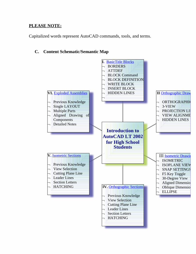
PLEASE NOTE:
Capitalized words represent AutoCAD commands, tools, and terms.
C. Content Schematic/Semantic Map
VI. Exploded Assemblies
¬ Previous Knowledge¬ Single LAYOUT¬ Multiple Parts¬ Aligned Drawing of
Components¬ Detailed Notes
V. Isometric Sections
¬ Previous Knowledge¬ View Selection¬ Cutting Plane Line¬ Leader Lines¬ Section Letters¬ HATCHING IV. Orthographic Sections
¬ Previous Knowledge¬ View Selection¬ Cutting Plane Line¬ Leader Lines¬ Section Letters¬ HATCHING
III Isometric Drawings¬ ISOMETRIC¬ ISOPLANE VIEWS ¬ SNAP SETTINGS¬ F5 Key Toggle¬ 30-Degree View¬ Aligned Dimensions¬ Oblique Dimensions¬ ELLIPSE
II Orthographic Drawings
¬ ORTHOGRAPHIC ¬ 3-VIEW¬ PROJECTION LINES¬ VIEW ALIGNMENT¬ HIDDEN LINES
I. BasicTitle Blocks¬ BORDERS¬ ATTDEF¬ BLOCK Command¬ BLOCK DEFINITION¬ WRITE BLOCK¬ INSERT BLOCK¬ HIDDEN LINES¬
Introduction toAutoCAD LT 2002
for High School Students
D. Appropriate Standards Achieved: Standards for Technology Literacy (STL) set forth by the International Technology Education Association (ITEA): Standard Eight – Students will develop an understanding of the Attributes of Design. Requirements for a design include such factors as the desired elements and feature of a product or system or the limits that are placed on the design. Standard Nine – Students will develop an understanding of Engineering Design. Expressing ideas to others verbally and through sketches and models is an important part of the design process. Standard Twelve – Students will develop the ability to use and maintain technological products and systems: Use computers and calculators to access, retrieve, organize process, maintain, interpret, and evaluate data and information in order to communicate. Standard Seventeen – Students will develop an understanding of and be able to select and use information and communication technologies: The use of symbols, measurements, and drawings promotes a clear communication by providing a common language to express ideas. Rhode Island Teacher Standards (RIBTS): RIBTS 5.3 – Make instructional decisions about when to provide information, when to clarify, when to pose a question, and when to let a student struggle to solve a problem. RIBTS 5.5 – Use tasks that engage students in exploration, discovery, and hands-on activities
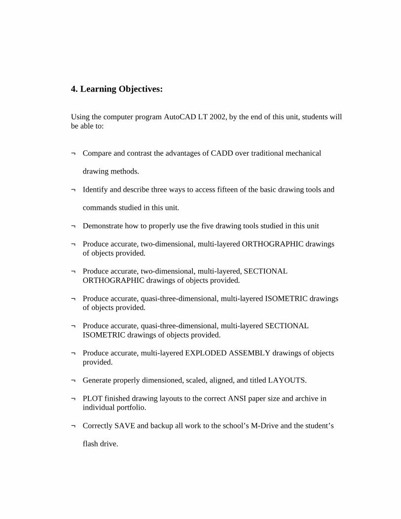
4. Learning Objectives: Using the computer program AutoCAD LT 2002, by the end of this unit, students will be able to: ¬ Compare and contrast the advantages of CADD over traditional mechanical
drawing methods.
¬ Identify and describe three ways to access fifteen of the basic drawing tools and
commands studied in this unit.
¬ Demonstrate how to properly use the five drawing tools studied in this unit
¬ Produce accurate, two-dimensional, multi-layered ORTHOGRAPHIC drawings of objects provided.
¬ Produce accurate, two-dimensional, multi-layered, SECTIONAL
ORTHOGRAPHIC drawings of objects provided. ¬ Produce accurate, quasi-three-dimensional, multi-layered ISOMETRIC drawings
of objects provided.
¬ Produce accurate, quasi-three-dimensional, multi-layered SECTIONAL ISOMETRIC drawings of objects provided.
¬ Produce accurate, multi-layered EXPLODED ASSEMBLY drawings of objects
provided.
¬ Generate properly dimensioned, scaled, aligned, and titled LAYOUTS.
¬ PLOT finished drawing layouts to the correct ANSI paper size and archive in individual portfolio.
¬ Correctly SAVE and backup all work to the school’s M-Drive and the student’s
flash drive.
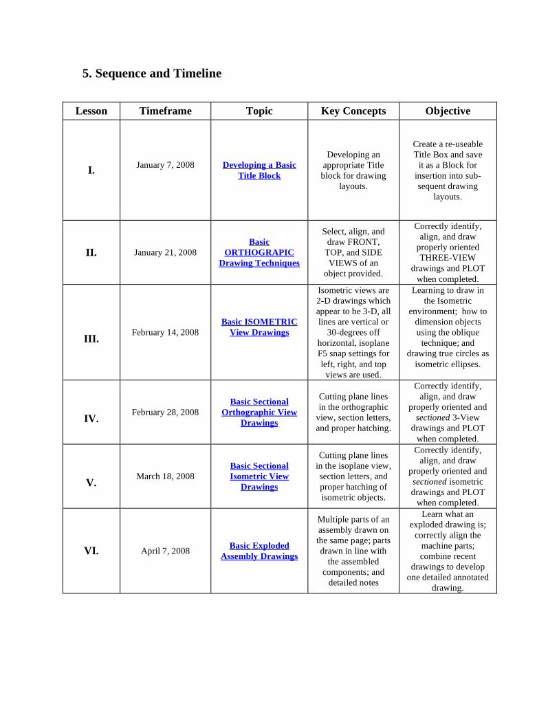
5. Sequence and Timeline
Lesson Timeframe Topic Key Concepts Objective
I.
January 7, 2008
Developing a Basic Title Block
Developing an
appropriate Title block for drawing
layouts.
Create a re-useable Title Box and save
it as a Block for insertion into sub- sequent drawing
layouts.
II.
January 21, 2008
Basic ORTHOGRAPIC
Drawing Techniques
Select, align, and draw FRONT,
TOP, and SIDE VIEWS of an
object provided.
Correctly identify, align, and draw
properly oriented THREE-VIEW
drawings and PLOT when completed.
III.
February 14, 2008
Basic ISOMETRIC View Drawings
Isometric views are 2-D drawings which appear to be 3-D, all lines are vertical or
30-degrees off horizontal, isoplane F5 snap settings for left, right, and top
views are used.
Learning to draw in the Isometric
environment; how to dimension objects using the oblique
technique; and drawing true circles as
isometric ellipses.
IV.
February 28, 2008
Basic Sectional Orthographic View
Drawings
Cutting plane lines in the orthographic
view, section letters, and proper hatching.
Correctly identify, align, and draw
properly oriented and sectioned 3-View
drawings and PLOT when completed.
V. March 18, 2008
Basic Sectional Isometric View
Drawings
Cutting plane lines in the isoplane view, section letters, and proper hatching of isometric objects.
Correctly identify, align, and draw
properly oriented and sectioned isometric drawings and PLOT
when completed.
VI. April 7, 2008 Basic Exploded Assembly Drawings
Multiple parts of an assembly drawn on the same page; parts drawn in line with
the assembled components; and
detailed notes
Learn what an exploded drawing is;
correctly align the machine parts; combine recent
drawings to develop one detailed annotated
drawing.
A. How will the unit accommodate for multicultural or family diversity? Although TECH-ED classes tend to be populated predominately by male students, female
students are strongly encouraged to enroll in these courses. The teacher shall discuss the
roles and employment opportunities for both males and females in the field of Computer
Aided Drafting and Design such as in the recent I-Way Bridge Project in Providence, RI
which employed engineer Ms. Patricia D. Steere, head of bridge design for The Maguire
Group. Also, regarding multi-cultural diversity, according to the 2007 Information
Works Report, this school’s population is very ethnically homogeneous (Ninety-eight
percent White and zero percent ESL population). Students will be exposed to the work of
male and female engineers and designers of ethnically diverse backgrounds during class
discussions.
B. Daily Activities/Prep for Teacher and Student
TEACHER STUDENTS Instructional routine PowerPoint Presentations Discussion Smart Board Demonstration L-Drive Uploads Individual Student Help
Drawing Assignments Projects Periodic Quizzes Portfolio Maintenance L-Drive Downloads Flash Drive Archiving
6. Assessment Students will be assessed in several ways. Initially, the teacher must make formative
assessments of students’ prior knowledge and possible misconceptions of mathematical,
geometric, and drafting concepts by way of introductory question and answer sessions. It
must first be determined if students: are able to properly dimension objects; perform
fractional mathematic calculations; are familiar with Standard and Metric forms of
measurement; understand shape and angle terminology; and possess a rudimentary
understanding of basic mechanical drawing concepts.
Subsequently, students will be formatively assessed by submitting both softcopy and
hardcopy versions of completed drawings which will count as class work assignments.
The hardcopy drawings will be archived in their individual three-ring binders for
submission to their Performance Based Graduation Requirement Portfolio (PBGR
Portfolio). These drawings must be accurate two-dimensional and quasi-three-
dimensional technical drawings plotted on the correct ANSI-size sheet of paper. The
softcopy drawings will be checked for flaws and accuracy by the teacher and receive a
grade. For each mistake five points is deducted. In some cases the students have the
opportunity to redraw and resubmit each corrected drawing at least twice and receive five
points less than the high score of the first redrawn submission, and ten points less for the
second submission.
Students will also be assessed for class participation. Taking part in class discussions
will count towards class participation. Students will have the opportunity to volunteer to
input data into teacher’s master workstation during the Smart Board CADD
demonstrations. Class attendance is considered an important part of class participation as
this is when students are actually completing practice drawing assignments during class
time.
Finally, students will be assessed by way of quizzes and exams administered in class.
Quizzes and exams will be both paper-based and computer-based. The traditional paper-
based test will help assess students’ general knowledge and comprehension of the
AutoCAD LT program’s workings. The computer-based quizzes are designed to assess
students’ performance using AutoCAD LT by measuring students’ abilities to apply,
analyze, synthesize, and evaluate how to use the various tools and techniques of actually
creating accurate technical drawings within a specified, finite time limit of an exam.
7. Resources Teacher Resources AutoCAD LT 2002 Software loaded on Workstation server

Computer Workstations for each student
Flash Drive on which to save CAD files
Handouts with isometric drawing models
Interactive Smart Board
L-Drive for uploading files
Laser Jet or Inkjet Printer
PowerPoint Presentations
Wooden 3-D Isometric Object Models
Texts:
AutoCAD LT 2002: Autodesk Getting Started (San Rafael, CA Autodesk, Inc. 2002), original owner’s manual for AutoCAD LT 2002 software package. Cheryl R. Schrock, AutoCAD Pocket Reference 2007 (New York: Industrial Press, 2007). David Byrnes and M. Middlebrook, AutoCAD 2007 for Dummies, (New Jersey: Wiley Pub 2006). Ted Saufley and Paul B. Schreiner, AutoCAD LT 2002: Fundamentals and Applications, Tinley Park, IL: Goodheart-Wilcox Publications, 2002). Randy H. Shih, AutoCAD LT 2002 Tutorial with Multi-Media CD (Kansas: Schroff Development Corporation Publications, 2002). Standards for Technological Literacy: Content for the Study of Technology (Reston, VA International Technology Educator’s Association, 2000). Student Resources
Flash Drive on which to save CADD files
Handouts with isometric drawing models
L-Drive Access
Three-ring Portfolio Binder
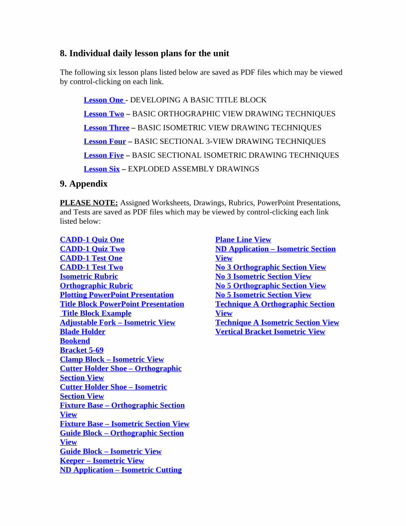
8. Individual daily lesson plans for the unit The following six lesson plans listed below are saved as PDF files which may be viewed by control-clicking on each link.
Lesson One - DEVELOPING A BASIC TITLE BLOCK
Lesson Two – BASIC ORTHOGRAPHIC VIEW DRAWING TECHNIQUES
Lesson Three – BASIC ISOMETRIC VIEW DRAWING TECHNIQUES
Lesson Four – BASIC SECTIONAL 3-VIEW DRAWING TECHNIQUES
Lesson Five – BASIC SECTIONAL ISOMETRIC DRAWING TECHNIQUES
Lesson Six – EXPLODED ASSEMBLY DRAWINGS
9. Appendix PLEASE NOTE: Assigned Worksheets, Drawings, Rubrics, PowerPoint Presentations, and Tests are saved as PDF files which may be viewed by control-clicking each link listed below: CADD-1 Quiz One CADD-1 Quiz Two CADD-1 Test One CADD-1 Test Two Isometric Rubric Orthographic Rubric Plotting PowerPoint Presentation Title Block PowerPoint Presentation Title Block Example Adjustable Fork – Isometric View Blade Holder Bookend Bracket 5-69 Clamp Block – Isometric View Cutter Holder Shoe – Orthographic Section View Cutter Holder Shoe – Isometric Section View Fixture Base – Orthographic Section View Fixture Base – Isometric Section View Guide Block – Orthographic Section View Guide Block – Isometric View Keeper – Isometric View ND Application – Isometric Cutting
Plane Line View ND Application – Isometric Section View No 3 Orthographic Section View No 3 Isometric Section View No 5 Orthographic Section View No 5 Isometric Section View Technique A Orthographic Section View Technique A Isometric Section View Vertical Bracket Isometric View
Teacher Name: Thomas Petteruti
Cooperating Teacher: Timothy McGee
Unit Title: CADD One — Introduction to Two Dimensional Drawing in AutoCAD
Grade Level: High School Tech Ed
Name of Lesson: Developing a basic Title Block in AutoCAD LT 2002
Introduction:
Once students are able to set up their drawings as layouts and plot them in AutoCAD LT 2002, the next
step they can undertake is the task of developing a basic Title Block. Title Blocks not only lend a more
professional appearance to the drawings, but they also contain important parameters and information
about the drawing itself. Once the border and title block are developed for one drawing, they can be
reused and modified for other drawings.
Lesson Goal:
The purpose of this lesson is to introduce high school students to the process used to develop and save a
re-useable, basic border and title block for two-dimensional line drawing layouts in the computer
program AutoCAD LT 2002.
Instructional Objectives (behavioral terminology, calls for measurable behavior) Cognitive
(Knowing,), Affective (Feeling) & Psychomotor (Doing) domains
As a result of participating in this lesson students will be able to:
1. Develop title box definitions with appropriate prompts such as NAME, DRAWTNG, SUBJECT, and
DATE.
2. Select the newly created title box in a window and change its properties to that of a BLOCK.
3. Save the newly created title block as a TEMPLATE in order to use it over again for insertion as a
BLOCK into previously completed drawing layouts.
Standards Achieved:
STL: (Standards for Technology Literacy ITEA K-12 Standards)
Standard Eight — Students will develop and understanding of the Attributes of Design. Requirements
for a design include such factors as the desired elements and feature of a product or system or the limits
that are placed on the design.
Standard Nine — Students will develop an understanding of Engineering Design. Expressing ideas to
others verbally and through sketches and models is an important part of the design process.
Standard Twelve — Students will develop the ability to use and maintain technological products and
systems: Use computers and calculators to access, retrieve, organize process, maintain, interpret, and
evaluate data and information in order to communicate.
Standard Seventeen — Students will develop an understanding of and be able to select and use
information and communication technologies: The use of symbols, measurements, and drawings
promotes a clear communication by providing a common language to express ideas.
RIBTS: (Rhode Island Teacher Standards)
RIBTS 5.3 — Make instructional decisions about when to provide information, when to clarify, when to
pose a question, and when to let a student struggle to solve a problem.
RIBTS 5.5 — Use tasks that engage students in exploration, discovery, and hands-on activities
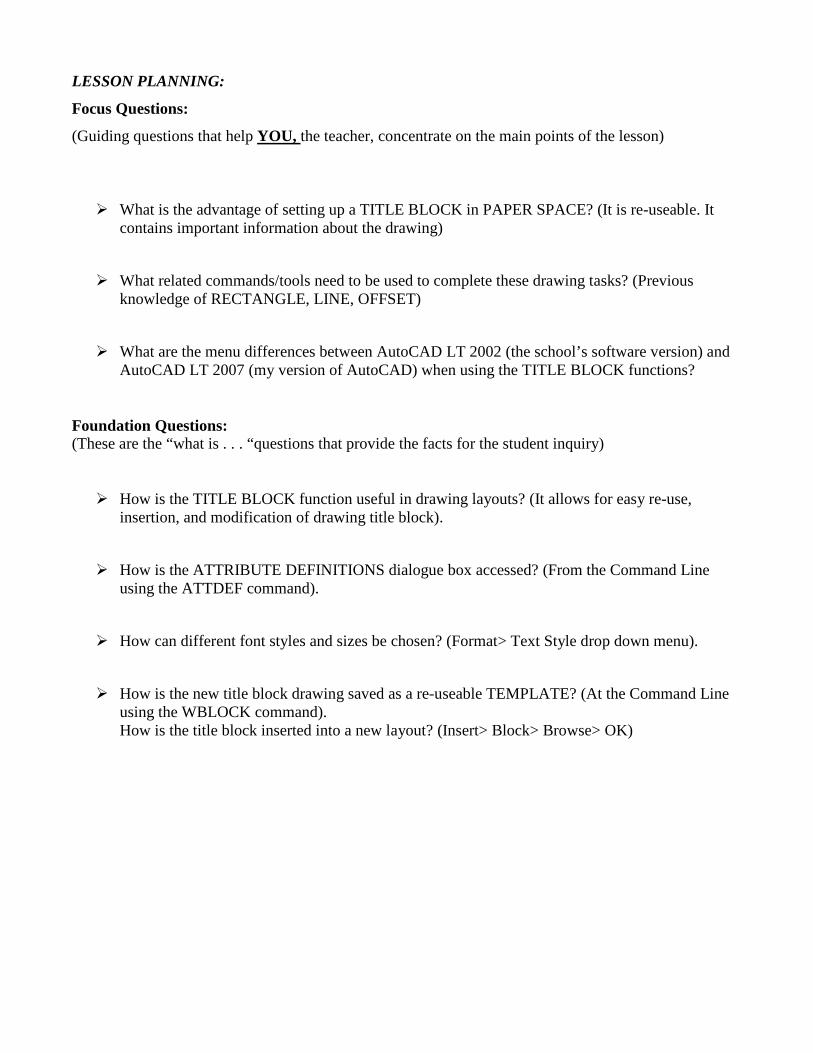
LESSON PLANNING:
Focus Questions:
(Guiding questions that help YOU, the teacher, concentrate on the main points of the lesson)
� What is the advantage of setting up a TITLE BLOCK in PAPER SPACE? (It is re-useable. It contains important information about the drawing)
� What related commands/tools need to be used to complete these drawing tasks? (Previous knowledge of RECTANGLE, LINE, OFFSET)
� What are the menu differences between AutoCAD LT 2002 (the school’s software version) and AutoCAD LT 2007 (my version of AutoCAD) when using the TITLE BLOCK functions?
Foundation Questions: (These are the “what is . . . “questions that provide the facts for the student inquiry)
� How is the TITLE BLOCK function useful in drawing layouts? (It allows for easy re-use, insertion, and modification of drawing title block).
� How is the ATTRIBUTE DEFINITIONS dialogue box accessed? (From the Command Line using the ATTDEF command).
� How can different font styles and sizes be chosen? (Format> Text Style drop down menu).
� How is the new title block drawing saved as a re-useable TEMPLATE? (At the Command Line using the WBLOCK command). How is the title block inserted into a new layout? (Insert> Block> Browse> OK)
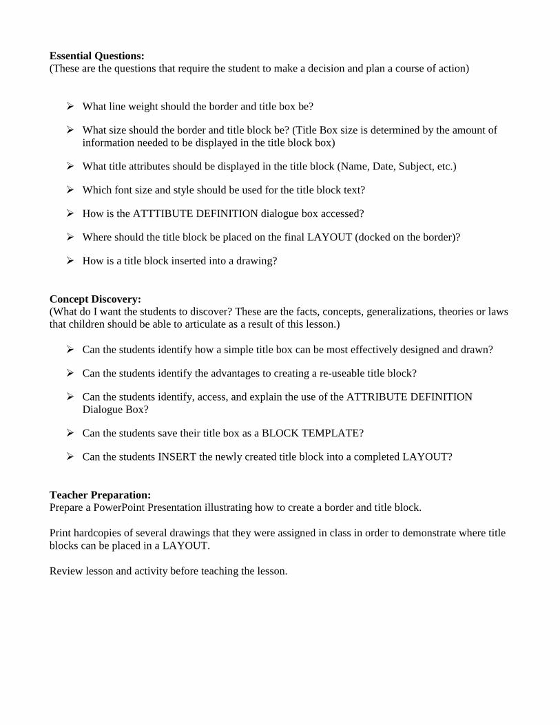
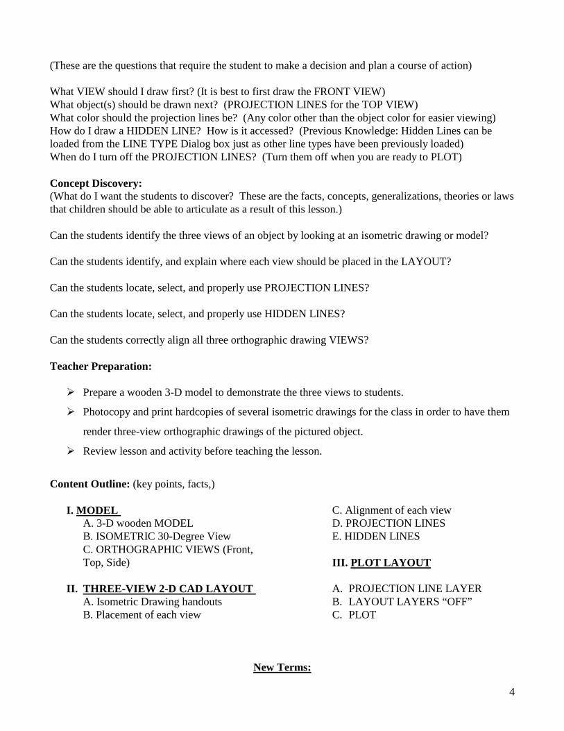
Essential Questions: (These are the questions that require the student to make a decision and plan a course of action)
� What line weight should the border and title box be?
� What size should the border and title block be? (Title Box size is determined by the amount of information needed to be displayed in the title block box)
� What title attributes should be displayed in the title block (Name, Date, Subject, etc.)
� Which font size and style should be used for the title block text?
� How is the ATTTIBUTE DEFINITION dialogue box accessed?
� Where should the title block be placed on the final LAYOUT (docked on the border)?
� How is a title block inserted into a drawing?
Concept Discovery: (What do I want the students to discover? These are the facts, concepts, generalizations, theories or laws that children should be able to articulate as a result of this lesson.)
� Can the students identify how a simple title box can be most effectively designed and drawn?
� Can the students identify the advantages to creating a re-useable title block?
� Can the students identify, access, and explain the use of the ATTRIBUTE DEFINITION Dialogue Box?
� Can the students save their title box as a BLOCK TEMPLATE?
� Can the students INSERT the newly created title block into a completed LAYOUT?
Teacher Preparation: Prepare a PowerPoint Presentation illustrating how to create a border and title block.
Print hardcopies of several drawings that they were assigned in class in order to demonstrate where title blocks can be placed in a LAYOUT.
Review lesson and activity before teaching the lesson.
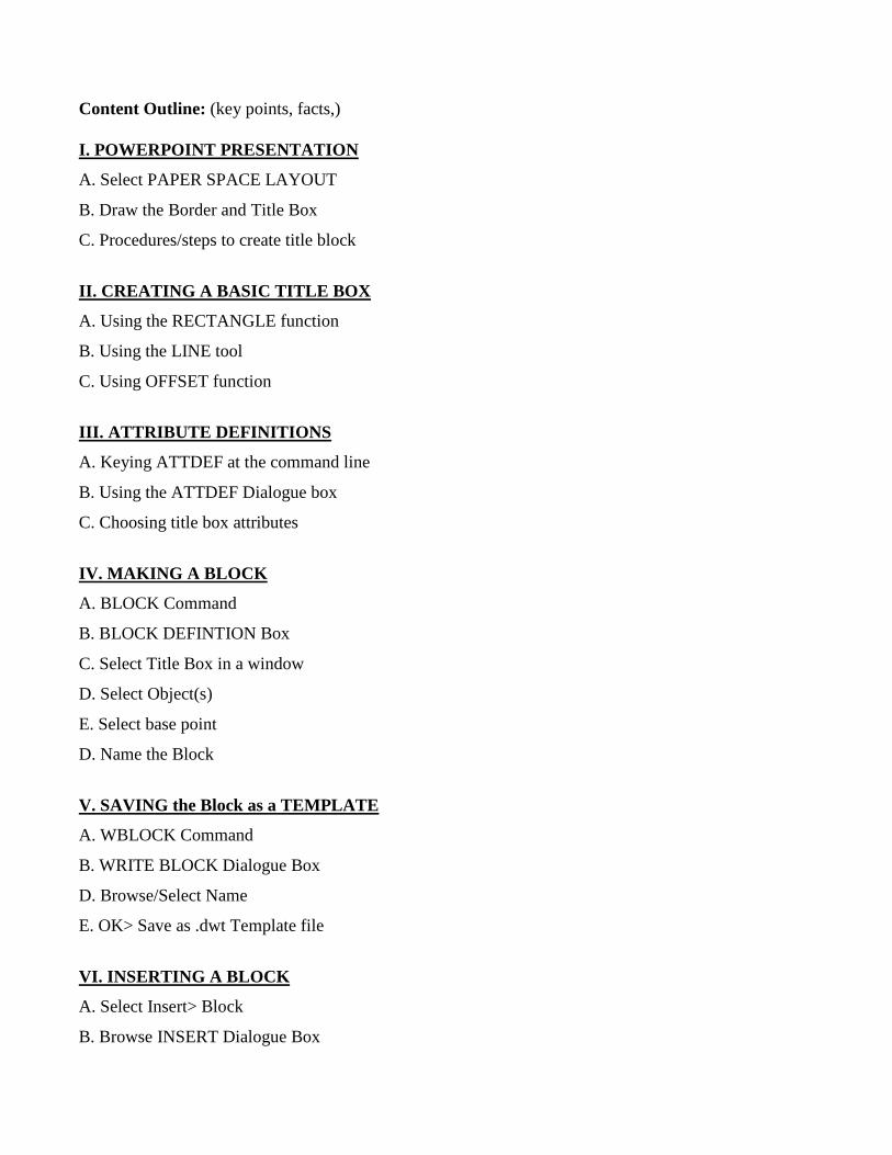
Content Outline: (key points, facts,)
I. POWERPOINT PRESENTATION
A. Select PAPER SPACE LAYOUT
B. Draw the Border and Title Box
C. Procedures/steps to create title block
II. CREATING A BASIC TITLE BOX
A. Using the RECTANGLE function
B. Using the LINE tool
C. Using OFFSET function
III. ATTRIBUTE DEFINITIONS
A. Keying ATTDEF at the command line
B. Using the ATTDEF Dialogue box
C. Choosing title box attributes
IV. MAKING A BLOCK
A. BLOCK Command
B. BLOCK DEFINTION Box
C. Select Title Box in a window
D. Select Object(s)
E. Select base point
D. Name the Block
V. SAVING the Block as a TEMPLATE
A. WBLOCK Command
B. WRITE BLOCK Dialogue Box
D. Browse/Select Name
E. OK> Save as .dwt Template file
VI. INSERTING A BLOCK
A. Select Insert> Block
B. Browse INSERT Dialogue Box
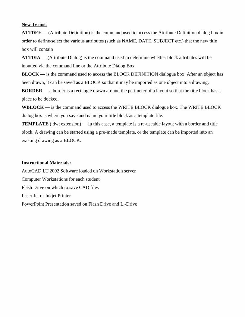
New Terms:
ATTDEF — (Attribute Definition) is the command used to access the Attribute Definition dialog box in
order to define/select the various attributes (such as NAME, DATE, SUBJECT etc.) that the new title
box will contain
ATTDIA — (Attribute Dialog) is the command used to determine whether block attributes will be
inputted via the command line or the Attribute Dialog Box.
BLOCK — is the command used to access the BLOCK DEFINITION dialogue box. After an object has
been drawn, it can be saved as a BLOCK so that it may be imported as one object into a drawing.
BORDER — a border is a rectangle drawn around the perimeter of a layout so that the title block has a
place to be docked.
WBLOCK — is the command used to access the WRITE BLOCK dialogue box. The WRITE BLOCK
dialog box is where you save and name your title block as a template file.
TEMPLATE (.dwt extension) — in this case, a template is a re-useable layout with a border and title
block. A drawing can be started using a pre-made template, or the template can be imported into an
existing drawing as a BLOCK.
Instructional Materials:
AutoCAD LT 2002 Software loaded on Workstation server
Computer Workstations for each student
Flash Drive on which to save CAD files
Laser Jet or Inkjet Printer
PowerPoint Presentation saved on Flash Drive and L.-Drive
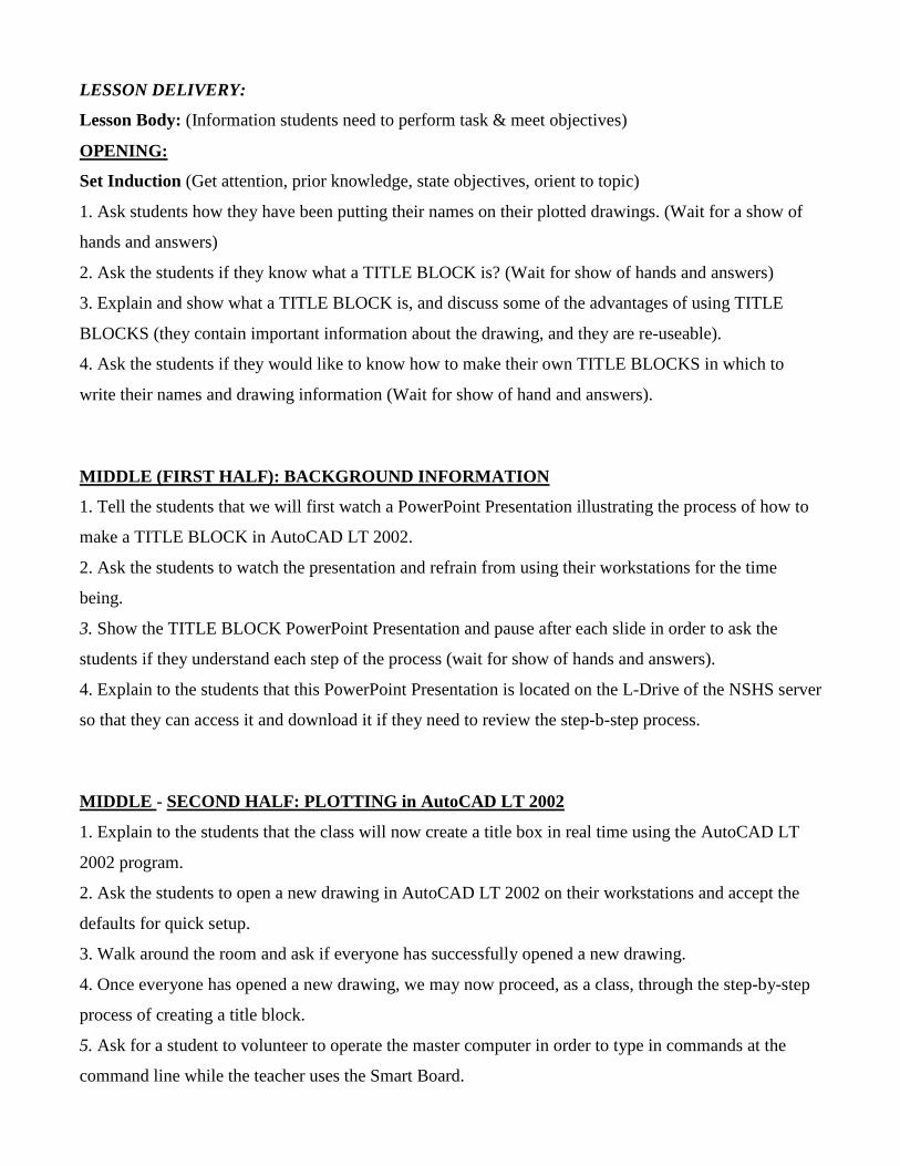
LESSON DELIVERY:
Lesson Body: (Information students need to perform task & meet objectives)
OPENING:
Set Induction (Get attention, prior knowledge, state objectives, orient to topic)
1. Ask students how they have been putting their names on their plotted drawings. (Wait for a show of
hands and answers)
2. Ask the students if they know what a TITLE BLOCK is? (Wait for show of hands and answers)
3. Explain and show what a TITLE BLOCK is, and discuss some of the advantages of using TITLE
BLOCKS (they contain important information about the drawing, and they are re-useable).
4. Ask the students if they would like to know how to make their own TITLE BLOCKS in which to
write their names and drawing information (Wait for show of hand and answers).
MIDDLE (FIRST HALF): BACKGROUND INFORMATION
1. Tell the students that we will first watch a PowerPoint Presentation illustrating the process of how to
make a TITLE BLOCK in AutoCAD LT 2002.
2. Ask the students to watch the presentation and refrain from using their workstations for the time
being.
3. Show the TITLE BLOCK PowerPoint Presentation and pause after each slide in order to ask the
students if they understand each step of the process (wait for show of hands and answers).
4. Explain to the students that this PowerPoint Presentation is located on the L-Drive of the NSHS server
so that they can access it and download it if they need to review the step-b-step process.
MIDDLE - SECOND HALF: PLOTTING in AutoCAD LT 2002
1. Explain to the students that the class will now create a title box in real time using the AutoCAD LT
2002 program.
2. Ask the students to open a new drawing in AutoCAD LT 2002 on their workstations and accept the
defaults for quick setup.
3. Walk around the room and ask if everyone has successfully opened a new drawing.
4. Once everyone has opened a new drawing, we may now proceed, as a class, through the step-by-step
process of creating a title block.
5. Ask for a student to volunteer to operate the master computer in order to type in commands at the
command line while the teacher uses the Smart Board.
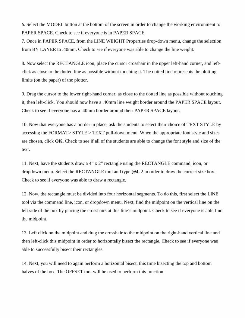
6. Select the MODEL button at the bottom of the screen in order to change the working environment to
PAPER SPACE. Check to see if everyone is in PAPER SPACE.
7. Once in PAPER SPACE, from the LINE WEIGHT Properties drop-down menu, change the selection
from BY LAYER to .40mm. Check to see if everyone was able to change the line weight.
8. Now select the RECTANGLE icon, place the cursor crosshair in the upper left-hand corner, and left-
click as close to the dotted line as possible without touching it. The dotted line represents the plotting
limits (on the paper) of the plotter.
9. Drag the cursor to the lower right-hand corner, as close to the dotted line as possible without touching
it, then left-click. You should now have a .40mm line weight border around the PAPER SPACE layout.
Check to see if everyone has a .40mm border around their PAPER SPACE layout.
10. Now that everyone has a border in place, ask the students to select their choice of TEXT STYLE by
accessing the FORMAT> STYLE > TEXT pull-down menu. When the appropriate font style and sizes
are chosen, click OK. Check to see if all of the students are able to change the font style and size of the
text.
11. Next, have the students draw a 4” x 2” rectangle using the RECTANGLE command, icon, or
dropdown menu. Select the RECTANGLE tool and type @4, 2 in order to draw the correct size box.
Check to see if everyone was able to draw a rectangle.
12. Now, the rectangle must be divided into four horizontal segments. To do this, first select the LINE
tool via the command line, icon, or dropdown menu. Next, find the midpoint on the vertical line on the
left side of the box by placing the crosshairs at this line’s midpoint. Check to see if everyone is able find
the midpoint.
13. Left click on the midpoint and drag the crosshair to the midpoint on the right-hand vertical line and
then left-click this midpoint in order to horizontally bisect the rectangle. Check to see if everyone was
able to successfully bisect their rectangles.
14. Next, you will need to again perform a horizontal bisect, this time bisecting the top and bottom
halves of the box. The OFFSET tool will be used to perform this function.
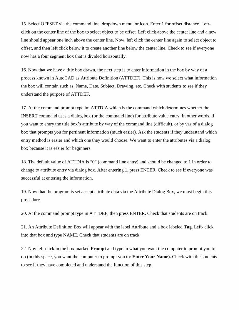
15. Select OFFSET via the command line, dropdown menu, or icon. Enter 1 for offset distance. Left-
click on the center line of the box to select object to be offset. Left click above the center line and a new
line should appear one inch above the center line. Now, left click the center line again to select object to
offset, and then left click below it to create another line below the center line. Check to see if everyone
now has a four segment box that is divided horizontally.
16. Now that we have a title box drawn, the next step is to enter information in the box by way of a
process known in AutoCAD as Attribute Definition (ATTDEF). This is how we select what information
the box will contain such as, Name, Date, Subject, Drawing, etc. Check with students to see if they
understand the purpose of ATTDEF.
17. At the command prompt type in: ATTDIA which is the command which determines whether the
INSERT command uses a dialog box (or the command line) for attribute value entry. In other words, if
you want to entry the title box’s attribute by way of the command line (difficult). or by vas of a dialog
box that prompts you for pertinent information (much easier). Ask the students if they understand which
entry method is easier and which one they would choose. We want to enter the attributes via a dialog
box because it is easier for beginners.
18. The default value of ATTDIA is “0” (command line entry) and should be changed to 1 in order to
change to attribute entry via dialog box. After entering 1, press ENTER. Check to see if everyone was
successful at entering the information.
19. Now that the program is set accept attribute data via the Attribute Dialog Box, we must begin this
procedure.
20. At the command prompt type in ATTDEF, then press ENTER. Check that students are on track.
21. An Attribute Definition Box will appear with the label Attribute and a box labeled Tag. Left- click
into that box and type NAME. Check that students are on track.
22. Nov left-click in the box marked Prompt and type in what you want the computer to prompt you to
do (in this space, you want the computer to prompt you to: Enter Your Name). Check with the students
to see if they have completed and understand the function of this step.
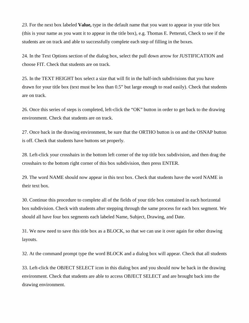
23. For the next box labeled Value, type in the default name that you want to appear in your title box
(this is your name as you want it to appear in the title box), e.g. Thomas E. Petteruti, Check to see if the
students are on track and able to successfully complete each step of filling in the boxes.
24. In the Text Options section of the dialog box, select the pull down arrow for JUSTIFICATION and
choose FIT. Check that students are on track.
25. In the TEXT HEIGHT box select a size that will fit in the half-inch subdivisions that you have
drawn for your title box (text must be less than 0.5” but large enough to read easily). Check that students
are on track.
26. Once this series of steps is completed, left-click the “OK” button in order to get back to the drawing
environment. Check that students are on track.
27. Once back in the drawing environment, be sure that the ORTHO button is on and the OSNAP button
is off. Check that students have buttons set properly.
28. Left-click your crosshairs in the bottom left corner of the top title box subdivision, and then drag the
crosshairs to the bottom right corner of this box subdivision, then press ENTER.
29. The word NAME should now appear in this text box. Check that students have the word NAME in
their text box.
30. Continue this procedure to complete all of the fields of your title box contained in each horizontal
box subdivision. Check with students after stepping through the same process for each box segment. We
should all have four box segments each labeled Name, Subject, Drawing, and Date.
31. We now need to save this title box as a BLOCK, so that we can use it over again for other drawing
layouts.
32. At the command prompt type the word BLOCK and a dialog box will appear. Check that all students
33. Left-click the OBJECT SELECT icon in this dialog box and you should now be back in the drawing
environment. Check that students are able to access OBJECT SELECT and are brought back into the
drawing environment.
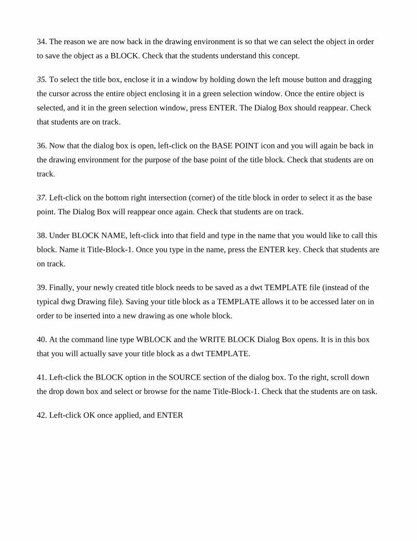
34. The reason we are now back in the drawing environment is so that we can select the object in order
to save the object as a BLOCK. Check that the students understand this concept.
35. To select the title box, enclose it in a window by holding down the left mouse button and dragging
the cursor across the entire object enclosing it in a green selection window. Once the entire object is
selected, and it in the green selection window, press ENTER. The Dialog Box should reappear. Check
that students are on track.
36. Now that the dialog box is open, left-click on the BASE POINT icon and you will again be back in
the drawing environment for the purpose of the base point of the title block. Check that students are on
track.
37. Left-click on the bottom right intersection (corner) of the title block in order to select it as the base
point. The Dialog Box will reappear once again. Check that students are on track.
38. Under BLOCK NAME, left-click into that field and type in the name that you would like to call this
block. Name it Title-Block-1. Once you type in the name, press the ENTER key. Check that students are
on track.
39. Finally, your newly created title block needs to be saved as a dwt TEMPLATE file (instead of the
typical dwg Drawing file). Saving your title block as a TEMPLATE allows it to be accessed later on in
order to be inserted into a new drawing as one whole block.
40. At the command line type WBLOCK and the WRITE BLOCK Dialog Box opens. It is in this box
that you will actually save your title block as a dwt TEMPLATE.
41. Left-click the BLOCK option in the SOURCE section of the dialog box. To the right, scroll down
the drop down box and select or browse for the name Title-Block-1. Check that the students are on task.
42. Left-click OK once applied, and ENTER
CLOSURE: (wrap up, questions, restate objectives, summary)
� Briefly review the topics covered in the PowerPoint Presentation, and remind the students that the presentation is located on the L-drive if they need to access it.
� Conduct a brief question and answer session regarding the steps for creating a title block.
� Inform/remind the students that, for three of their previously completed drawings and all of their subsequent drawings, they must TNSERT a TITLE BLOCK in the LAYOUT before they PLOT them, and then store the hardcopies in a binder so that they can be submitted for a “homework” grade.
ASSESSMENT:
� Identify where the page border should be placed (within the page limit dotted line indicator).
� Create a page border and identify its main purpose (a place at which to dock the title block)
� Draw a rectangular title box divided into four segments.
� Identify ATTDIA command and its function (it allows you to access the attribute dialogue box)
� Identify and explain how to access and use the Attribute Definition Dialogue Box.
� Save the newly created title block as a TEMPLATE.
� Insert the title block into three previous drawings and all subsequent drawings.
� Plot three previously completed drawings for individual student portfolio.
� Save completed drawing on hard drive and flash drive.
� The three drawings will be graded and be counted as homework assignments.
� This title block development process will be covered on the next exam.
Follow-up, Future Investigation, & Reference
Sources: AutoCAD LT 2002: Autodesk Getting Started (San Rafael, CA Autodesk, Inc 2002), original manual that comes with the AutoCAD LT 2002 software package.
Cheryl R. Schrock, AutoCAD Pocket Reference 2007 (New York: Industrial Press, 2007), 6-2 to 6-12.
David Byrnes and Mark Middlebrook, AutoCAD 2007 for Dummies, (New Jersey: Wiley Publishing 2006) 105-116.
Randy H. Shih, AutoCAD LT 2002 Tutorial with Multi-Media CD, (Kansas: Schroff Development Corporation Publications, 2002).
Cooperating Teacher(s) Approval:
Name: ____________________________ Date: ____________
Name: ____________________________ Date: ____________
12
11116 211
16
514
458 15
8
2 916
1516
1516
R38
114
1116
12
1116
158
716
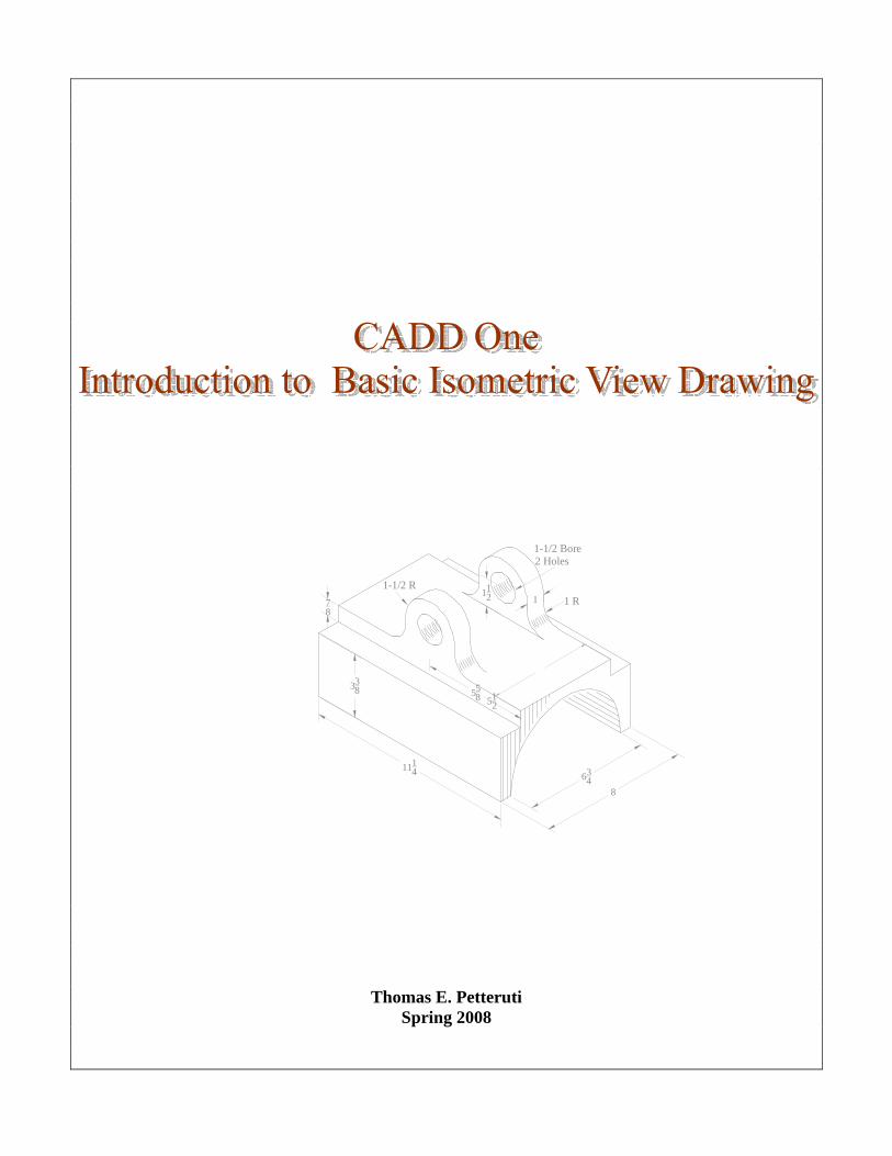
Thomas E. Petteruti
Spring 2008
2
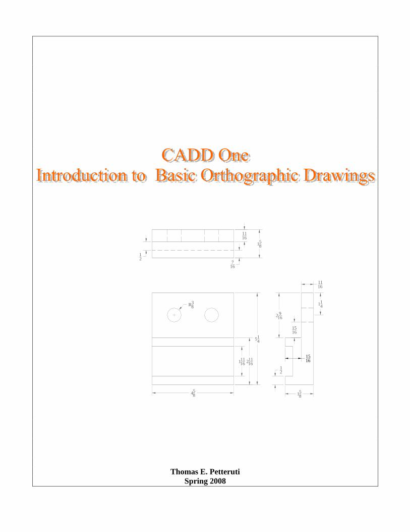
Teacher Name: Thomas Petteruti Cooperating Teacher: Timothy McGee Unit Title: CADD One – Introduction to Two Dimensional Drawing in AutoCAD Grade Level: High School Tech Ed
Name of Lesson: Basic Three-View Drawing in AutoCAD LT 2002 Introduction: After becoming acclimated with many of the basic single-view, two-dimensional drawing functions, tools, menus, and icons in AutoCAD LT 2002, students will next be introduced to applying these tools and techniques to basic three-view ORTHOGRAPHIC drawings of objects. Lesson Goal: The purpose of this lesson is to introduce high school students to the basic techniques used for completing two-dimensional, three-view drawings in the computer program AutoCAD LT 2002. Instructional Objectives (behavioral terminology, calls for measurable behavior) Cognitive (Knowing), Affective (Feeling) & Psychomotor (Doing) domains As a result of participating in this lesson students will be able to: 1. Correctly identify the FRONT, SIDE, and TOP views of an isometric drawing and/or actual object. 2. Select the proper placement for each view in the layout. 3. Properly position the projection lines in order to align the three views correctly. 4. Students will be able plot the three-view layout to an 8.5” x 11.0” piece of paper on the lab’s standard LaserJet printer. Standards Achieved: STL: (Standards for Technology Literacy ITEA K-12 Standards) Standard Eight – Students will develop and understanding of the Attributes of Design. Requirements for a design include such factors as the desired elements and feature of a product or system or the limits that are placed on the design. Standard Nine – Students will develop an understanding of Engineering Design. Expressing ideas to others verbally and through sketches and models is an important part of the design process.

3
Standard Twelve – Students will develop the ability to use and maintain technological products and systems: Use computers and calculators to access, retrieve, organize process, maintain, interpret, and evaluate data and information in order to communicate. Standard Seventeen – Students will develop an understanding of and be able to select and use information and communication technologies: The use of symbols, measurements, and drawings promotes a clear communication by providing a common language to express ideas. RIBTS: (Rhode Island Teacher Standards) RIBTS 5.3 – Make instructional decisions about when to provide information, when to clarify, when to pose a question, and when to let a student struggle to solve a problem. RIBTS 5.5 – Use tasks that engage students in exploration, discovery, and hands-on activities LESSON PLANNING: Focus Questions: (Guiding questions that help YOU, the teacher, concentrate on the main points of the lesson)
� Would an actual three-dimensional model be helpful in explaining FRONT, SIDE, and TOP VIEWS? (Students can examine model to determine various views)
� What related commands/tools need to be used to complete these drawing tasks? (Previous knowledge)
� What new knowledge and drawing techniques do students need to know? (The use of PROJECTION LINES and HIDDEN LINES)
� What are the menu differences between AutoCAD LT 2002 (the school’s software version) and AutoCAD LT 2007 (my version of AutoCAD) when using the MODEL SPACE/LAYOUT functions?
Foundation Questions: (These are the “what is . . .” questions that provide the facts for the student inquiry)
� How do you determine which view is the FRONT, TOP, or SIDE? (Having an actual 3-D model will help determine the necessary views according to detail and orientation).
� Where does each view reside in the layout? (TOP is upper left, FRONT is lower left, and SIDE is lower right on the layout)
� What are HIDDEN LINES? (They are dotted lines that are used to indicate holes, objects, or structures that are visible in some views of the object but not visible in other views of the object)
� Are HIDDEN LINES a part of the plotted drawing? (Yes, they are to be plotted) � What are PROJECTION LINES? (They are horizontal and vertical lines that are used to help
draw all three views in line with each other) � Are PROJECTION LINES a part of the plotted drawing? (No, they can be drawn on a separate
layer and turned “off” when plotting) Essential Questions:
4
(These are the questions that require the student to make a decision and plan a course of action) What VIEW should I draw first? (It is best to first draw the FRONT VIEW) What object(s) should be drawn next? (PROJECTION LINES for the TOP VIEW) What color should the projection lines be? (Any color other than the object color for easier viewing) How do I draw a HIDDEN LINE? How is it accessed? (Previous Knowledge: Hidden Lines can be loaded from the LINE TYPE Dialog box just as other line types have been previously loaded) When do I turn off the PROJECTION LINES? (Turn them off when you are ready to PLOT) Concept Discovery: (What do I want the students to discover? These are the facts, concepts, generalizations, theories or laws that children should be able to articulate as a result of this lesson.) Can the students identify the three views of an object by looking at an isometric drawing or model? Can the students identify, and explain where each view should be placed in the LAYOUT? Can the students locate, select, and properly use PROJECTION LINES? Can the students locate, select, and properly use HIDDEN LINES? Can the students correctly align all three orthographic drawing VIEWS? Teacher Preparation:
� Prepare a wooden 3-D model to demonstrate the three views to students.
� Photocopy and print hardcopies of several isometric drawings for the class in order to have them
render three-view orthographic drawings of the pictured object.
� Review lesson and activity before teaching the lesson.
Content Outline: (key points, facts,)
I. MODEL A. 3-D wooden MODEL B. ISOMETRIC 30-Degree View C. ORTHOGRAPHIC VIEWS (Front,
Top, Side) II. THREE-VIEW 2-D CAD LAYOUT
A. Isometric Drawing handouts B. Placement of each view
C. Alignment of each view D. PROJECTION LINES
E. HIDDEN LINES III. PLOT LAYOUT A. PROJECTION LINE LAYER B. LAYOUT LAYERS “OFF” C. PLOT
New Terms:
5
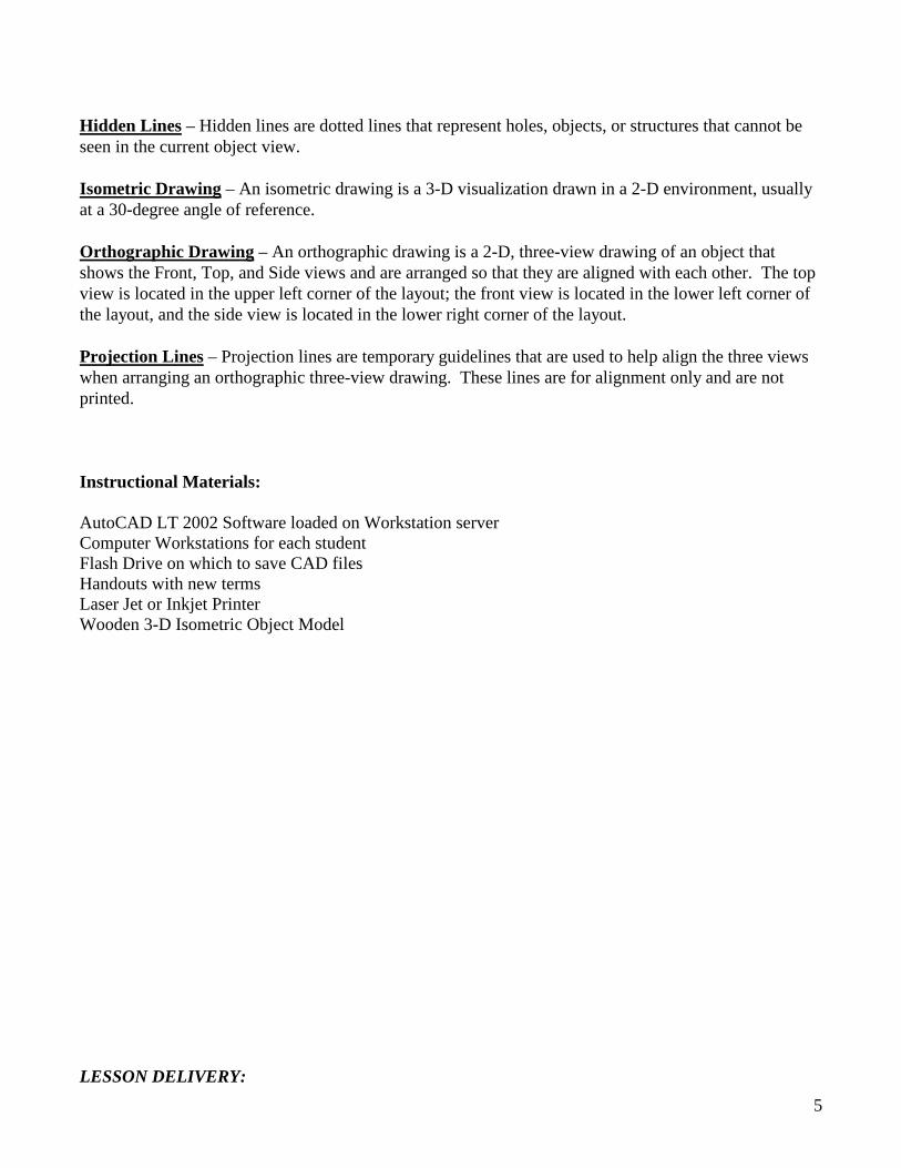
Hidden Lines – Hidden lines are dotted lines that represent holes, objects, or structures that cannot be seen in the current object view. Isometric Drawing – An isometric drawing is a 3-D visualization drawn in a 2-D environment, usually at a 30-degree angle of reference. Orthographic Drawing – An orthographic drawing is a 2-D, three-view drawing of an object that shows the Front, Top, and Side views and are arranged so that they are aligned with each other. The top view is located in the upper left corner of the layout; the front view is located in the lower left corner of the layout, and the side view is located in the lower right corner of the layout. Projection Lines – Projection lines are temporary guidelines that are used to help align the three views when arranging an orthographic three-view drawing. These lines are for alignment only and are not printed. Instructional Materials: AutoCAD LT 2002 Software loaded on Workstation server Computer Workstations for each student Flash Drive on which to save CAD files Handouts with new terms Laser Jet or Inkjet Printer Wooden 3-D Isometric Object Model LESSON DELIVERY:
6
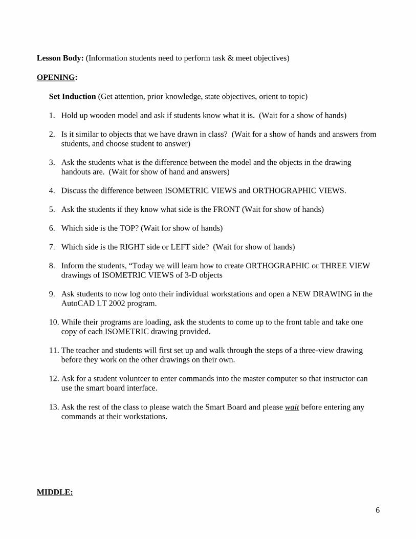
Lesson Body: (Information students need to perform task & meet objectives) OPENING:
Set Induction (Get attention, prior knowledge, state objectives, orient to topic)
1. Hold up wooden model and ask if students know what it is. (Wait for a show of hands) 2. Is it similar to objects that we have drawn in class? (Wait for a show of hands and answers from
students, and choose student to answer)
3. Ask the students what is the difference between the model and the objects in the drawing handouts are. (Wait for show of hand and answers)
4. Discuss the difference between ISOMETRIC VIEWS and ORTHOGRAPHIC VIEWS.
5. Ask the students if they know what side is the FRONT (Wait for show of hands)
6. Which side is the TOP? (Wait for show of hands)
7. Which side is the RIGHT side or LEFT side? (Wait for show of hands)
8. Inform the students, “Today we will learn how to create ORTHOGRAPHIC or THREE VIEW
drawings of ISOMETRIC VIEWS of 3-D objects 9. Ask students to now log onto their individual workstations and open a NEW DRAWING in the
AutoCAD LT 2002 program.
10. While their programs are loading, ask the students to come up to the front table and take one copy of each ISOMETRIC drawing provided.
11. The teacher and students will first set up and walk through the steps of a three-view drawing
before they work on the other drawings on their own. 12. Ask for a student volunteer to enter commands into the master computer so that instructor can
use the smart board interface.
13. Ask the rest of the class to please watch the Smart Board and please wait before entering any commands at their workstations.
MIDDLE:
7
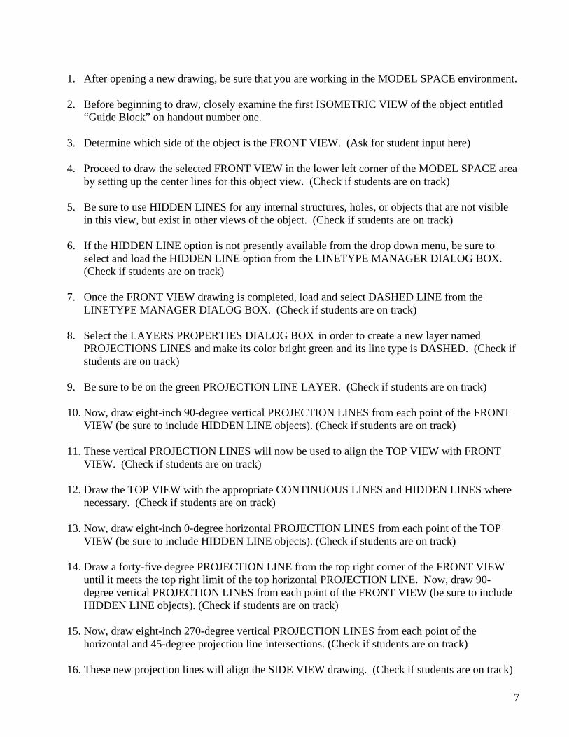
1. After opening a new drawing, be sure that you are working in the MODEL SPACE environment. 2. Before beginning to draw, closely examine the first ISOMETRIC VIEW of the object entitled
“Guide Block” on handout number one.
3. Determine which side of the object is the FRONT VIEW. (Ask for student input here)
4. Proceed to draw the selected FRONT VIEW in the lower left corner of the MODEL SPACE area by setting up the center lines for this object view. (Check if students are on track)
5. Be sure to use HIDDEN LINES for any internal structures, holes, or objects that are not visible
in this view, but exist in other views of the object. (Check if students are on track)
6. If the HIDDEN LINE option is not presently available from the drop down menu, be sure to select and load the HIDDEN LINE option from the LINETYPE MANAGER DIALOG BOX. (Check if students are on track)
7. Once the FRONT VIEW drawing is completed, load and select DASHED LINE from the
LINETYPE MANAGER DIALOG BOX. (Check if students are on track)
8. Select the LAYERS PROPERTIES DIALOG BOX in order to create a new layer named PROJECTIONS LINES and make its color bright green and its line type is DASHED. (Check if students are on track)
9. Be sure to be on the green PROJECTION LINE LAYER. (Check if students are on track)
10. Now, draw eight-inch 90-degree vertical PROJECTION LINES from each point of the FRONT
VIEW (be sure to include HIDDEN LINE objects). (Check if students are on track)
11. These vertical PROJECTION LINES will now be used to align the TOP VIEW with FRONT VIEW. (Check if students are on track)
12. Draw the TOP VIEW with the appropriate CONTINUOUS LINES and HIDDEN LINES where
necessary. (Check if students are on track)
13. Now, draw eight-inch 0-degree horizontal PROJECTION LINES from each point of the TOP VIEW (be sure to include HIDDEN LINE objects). (Check if students are on track)
14. Draw a forty-five degree PROJECTION LINE from the top right corner of the FRONT VIEW
until it meets the top right limit of the top horizontal PROJECTION LINE. Now, draw 90-degree vertical PROJECTION LINES from each point of the FRONT VIEW (be sure to include HIDDEN LINE objects). (Check if students are on track)
15. Now, draw eight-inch 270-degree vertical PROJECTION LINES from each point of the
horizontal and 45-degree projection line intersections. (Check if students are on track)
16. These new projection lines will align the SIDE VIEW drawing. (Check if students are on track)
8
17. Draw the SIDE VIEW in line with the vertical PROJECTIONS LINES. (Check if students are
on track)
18. You should now a have a properly aligned THREE-VIEW ORTHOGRAPHIC drawing! (Check if students are on track)
19. Enter the proper dimensions for each view, set up a LAYOUT in PAPER SPACE, and PLOT
this drawing. CLOSURE: (wrap up, questions, restate objectives, summary)
� Conduct a brief question and answer session regarding the THREE-VIEW drawing process.
� Inform/remind the students that they must PLOT all subsequent completed drawings for the
remainder of this class and in subsequent classes, store them in a binder, and submit them for a “homework” grade.
ASSESSMENT:
� Identify and name ISOMETRIC type drawing and its features. � Distinguish between and describe the THREE VIEWS of an ORTHOGRAPIC drawing. � Identify and explain how to access and use PROJECTION LINES. � Complete and plot twenty ORTHOGRAPHIC drawings for individual student portfolio. � Save completed drawing on hard drive and flash drive. � The twenty drawings will be graded and be counted as homework assignments.
Follow-up, Future Investigation, & Reference
Sources:
AutoCAD LT 2002: Autodesk Getting Started (San Rafael, CA Autodesk, Inc. 2002), original owner’s manual for AutoCAD LT 2002 software package. Cheryl R. Schrock, AutoCAD Pocket Reference 2007 (New York: Industrial Press, 2007), 6-2 to 6-12. David Byrnes and Mark Middlebrook, AutoCAD 2007 for Dummies, (New Jersey: Wiley Publishing 2006) 105-116. Randy H. Shih, AutoCAD LT 2002 Tutorial with Multi-Media CD (Kansas: Schroff Development Corporation Publications, 2002).
Cooperating Teacher(s) Approval:
Name: ________________________ Date: ____/_____/______
Name: ________________________ Date: ____/_____/_____
1114
558
78
338
1-1/2 R
8
634
112
512
1
1-1/2 Bore2 Holes
1 R
Thomas E. Petteruti Spring 2008

2
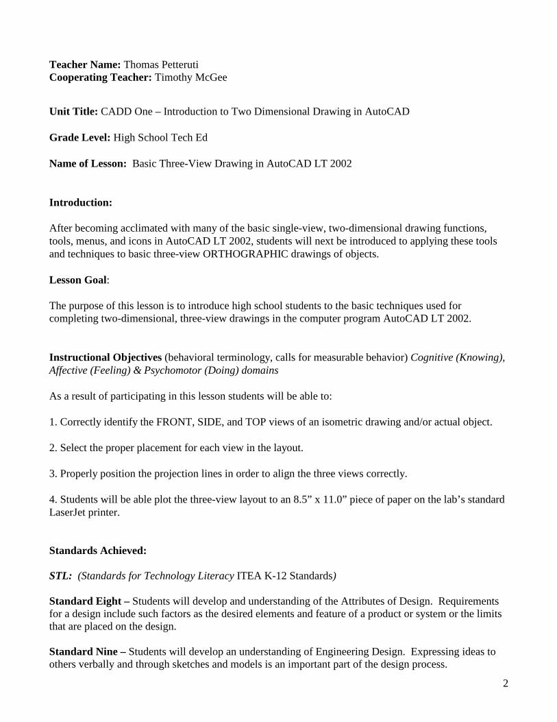
Teacher Name: Thomas Petteruti Cooperating Teacher: Timothy McGee School: North Smithfield High School Unit Title: CADD One – Introduction to Two Dimensional Drawing in AutoCAD Grade Level: High School Tech Ed Grades Nine through Twelve
Name of Lesson: Isometric-View Drawing in AutoCAD LT 2002 Introduction: After becoming acclimated with orthographic three-view drawing functions, tools, menus, and icons in AutoCAD LT 2002, students will next be introduced to applying these drawings and corresponding dimensions in order to render more advanced isometric-view drawings of objects in order to convey a three-dimensional ISOMETRIC effect. Lesson Goal: The purpose of this lesson is to introduce high school students to the basic techniques used for completing isometric view drawings in the computer program AutoCAD LT 2002. Isometric view drawings are used to illustrate objects at a thirty-degree angle in a three-dimensional-like rendering. The assigned isometric view drawings are based upon orthographic drawings and dimensions previously completed by the students, which helps in understanding the various parameters and dimensions of the ISOMETRIC view more clearly. Instructional Objectives (behavioral terminology, calls for measurable behavior) Cognitive (Knowing), Affective (Feeling) & Psychomotor (Doing) domains As a result of participating in this lesson students will be able to: 1. Correctly identify an ISOMETRIC VIEW drawing. 2. Determine the best POSITION (thirty-degree angle showing the most detail) at which view and draw the object. 3. Identify and select the correct SNAP TYPE and STYLE SETTING associated with Isometric view drawing (the ISOMETRIC SNAP TYPE SETTING). 4. Identify the three ISOMETRIC PLANES: LEFT, RIGHT, and TOP. 5. Identify and select the correct FUNCTION KEY (F5) for setting the desired ISOMETRIC PLANE crosshair cursor setting.
3
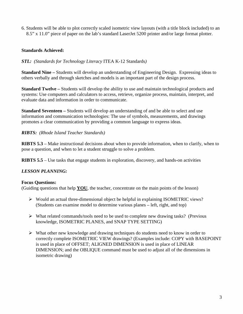
6. Students will be able to plot correctly scaled isometric view layouts (with a title block included) to an 8.5” x 11.0” piece of paper on the lab’s standard LaserJet 5200 printer and/or large format plotter. Standards Achieved: STL: (Standards for Technology Literacy ITEA K-12 Standards) Standard Nine – Students will develop an understanding of Engineering Design. Expressing ideas to others verbally and through sketches and models is an important part of the design process. Standard Twelve – Students will develop the ability to use and maintain technological products and systems: Use computers and calculators to access, retrieve, organize process, maintain, interpret, and evaluate data and information in order to communicate. Standard Seventeen – Students will develop an understanding of and be able to select and use information and communication technologies: The use of symbols, measurements, and drawings promotes a clear communication by providing a common language to express ideas. RIBTS: (Rhode Island Teacher Standards) RIBTS 5.3 – Make instructional decisions about when to provide information, when to clarify, when to pose a question, and when to let a student struggle to solve a problem. RIBTS 5.5 – Use tasks that engage students in exploration, discovery, and hands-on activities LESSON PLANNING: Focus Questions: (Guiding questions that help YOU, the teacher, concentrate on the main points of the lesson)
� Would an actual three-dimensional object be helpful in explaining ISOMETRIC views? (Students can examine model to determine various planes – left, right, and top)
� What related commands/tools need to be used to complete new drawing tasks? (Previous
knowledge, ISOMETRIC PLANES, and SNAP TYPE SETTING)
� What other new knowledge and drawing techniques do students need to know in order to correctly complete ISOMETRIC VIEW drawings? (Examples include: COPY with BASEPOINT is used in place of OFFSET; ALIGNED DIMENSION is used in place of LINEAR DIMENSION; and the OBLIQUE command must be used to adjust all of the dimensions in isometric drawing)
4
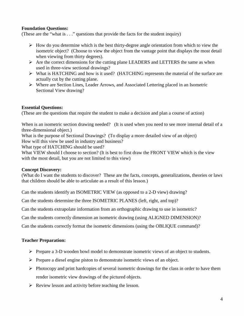
Foundation Questions: (These are the “what is . . .” questions that provide the facts for the student inquiry)
� How do you determine which is the best thirty-degree angle orientation from which to view the isometric object? (Choose to view the object from the vantage point that displays the most detail when viewing from thirty degrees).
� Are the correct dimensions for the cutting plane LEADERS and LETTERS the same as when used in three-view sectional drawings?
� What is HATCHING and how is it used? (HATCHING represents the material of the surface are actually cut by the cutting plane.
� Where are Section Lines, Leader Arrows, and Associated Lettering placed in an Isometric Sectional View drawing?
Essential Questions: (These are the questions that require the student to make a decision and plan a course of action) When is an isometric section drawing needed? (It is used when you need to see more internal detail of a three-dimensional object.) What is the purpose of Sectional Drawings? (To display a more detailed view of an object) How will this view be used in industry and business? What type of HATCHING should be used? What VIEW should I choose to section? (It is best to first draw the FRONT VIEW which is the view with the most detail, but you are not limited to this view) Concept Discovery: (What do I want the students to discover? These are the facts, concepts, generalizations, theories or laws that children should be able to articulate as a result of this lesson.) Can the students identify an ISOMETRIC VIEW (as opposed to a 2-D view) drawing?
Can the students determine the three ISOMETRIC PLANES (left, right, and top)?
Can the students extrapolate information from an orthographic drawing to use in isometric?
Can the students correctly dimension an isometric drawing (using ALIGNED DIMENSION)?
Can the students correctly format the isometric dimensions (using the OBLIQUE command)?
Teacher Preparation:
� Prepare a 3-D wooden bowl model to demonstrate isometric views of an object to students.
� Prepare a diesel engine piston to demonstrate isometric views of an object.
� Photocopy and print hardcopies of several isometric drawings for the class in order to have them
render isometric view drawings of the pictured objects.
� Review lesson and activity before teaching the lesson.
5
Content Outline: (key points, facts,)
I. MODELS A. 3-D wooden bowl MODEL B. Diesel Engine Piston C. Sheets containing Isometric Drawings II. SECTION-VIEW LAYOUT
A. Isometric drawing handouts B. Placement of CUTTING PLANE C. Aligning/Choosing Section View
D. Leader and Letter Placement E. HATCHING III. PLOT LAYOUT A. Viewport B. Proper Scale C. Title Block D. PLOT
New Terms:
Cutting Plane – The cutting plane is an imaginary plane that is used to “cut” and object into sections. Hatching – Hatching is an artistic technique used to create tonal or shading effects by drawing closely spaced parallel lines. Different hatching patterns are used to represent various materials. Leader Arrows – Leader arrows are used in sectional drawings in order to indicate the direction of the view looking toward the cutting plane. Section Line – Section lines are used to indicate cutting plane. Instructional Materials: AutoCAD LT 2002 Software loaded on Workstation/Network server Interactive Smart Board Computer Workstations for each student Flash Drive on which to save CAD files Handouts with new two dimensional isometric and orthographic drawings LaserJet Printer Wooden, sectioned, 3-D Bowl Model Diesel Engine Piston “C” sized section view piston drawing Isometric section view drawings Three-view section view drawings LESSON DELIVERY: Lesson Body: (Information students need to perform task & meet objectives) OPENING:
Set Induction (Get attention, prior knowledge, state objectives, orient to topic)
6
1. Discuss the difference between ISOMETRIC VIEWS and ORTHOGRAPHIC VIEWS.
2. Ask if anybody knows what a SECTIONAL VIEW of an object is. (Wait for a show of hands and then pick a student to explain.)
3. Using the sectioned wooden model and the diesel piston, explain and demonstrate what a
sectional view of an object is, and how and why these views are used.
4. Ask if anybody has any questions or if they would like to view the object more closely. (Wait for a show of hands).
5. Inform the students, “Today we will be introduced to a new method of viewing objects and learn
how to create SECTIONAL VIEW drawings using the computer program AutoCAD LT 2002.”
6. Show the piston and its interior, and the “C” size sheet drawing of the piston section view.
MIDDLE:
1. Open an AutoCAD drawing containing both orthographic and isometric views of an object
already drawn in class. 2. Ask the students which view in the ORTHOGRAPHIC drawing has the most detail (the front
view) and wait for a show of hands and response.
3. Explain the concept of an “imaginary cutting plane” slicing through the top view of the object at its centerline.
4. Point out the cutting plane line, leaders, and letters (the letter “A”) which denote the direction of
view (from the front) in relation to the top view. (see this link for PDF of drawing)
5. Ask the students if they understand the imaginary cutting plane concept and its corresponding, angle of view as indicated by the leader arrows and letters. (Wait for a show of hands and response)
6. Prompt students to compare the sectional view drawing to the wooden model and piston model.
(Wait for show of hands and input)
7. Explain that only the surfaces of the object that come into direct contact with the cutting plane must be filled with the proper HATCH pattern.
8. Demonstrate how to access the various HATCH patterns via the drop-down menu, command
line, and icon. (Check with students in order to ensure that they comprehend)
7
9. Point out the various hatch types and their corresponding material types (steel, brass, concrete, etc
10. Demonstrate the proper procedure for applying HATCH patterns to the cutting plane surfaces.
CLOSURE: (wrap up, questions, restate objectives, summary)
� Conduct a brief question and answer session regarding the SECTIONAL-VIEW drawing process. � Ask the students to use their previous knowledge in selecting the proper View port, Scale, and
Title Block in order to properly set up a Plotting Layout.
� Inform/remind the students that they must PLOT all subsequent completed drawings for the remainder of this class and in subsequent classes, store them in a binder, and submit them for a “homework” grade.
ASSESSMENT:
� Identify and name ISOMETRIC SECTIONAL VIEW drawing and its features. � Identify and describe the concept of the CUTTING PLANE in an ISOMETRIC SECTIONAL
VIEW drawing. � Identify and explain the proper placement and dimensions of CUTTING PLANE LINES,
LEADERS, and ARROWS in an ISOMETRIC SECTIONAL VIEW drawing. � Complete and plot twenty ISOMETRIC SECTIONAL VIEW drawings for individual student
portfolio. � Save completed drawing on hard drive and flash drive. � The twenty drawings will be graded and be counted as homework assignments.
Follow-up, Future Investigation, & Reference
Sources:
AutoCAD LT 2002: Autodesk Getting Started (San Rafael, CA Autodesk, Inc. 2002), original owner’s manual for AutoCAD LT 2002 software package. Cheryl R. Schrock, AutoCAD Pocket Reference 2007 (New York: Industrial Press, 2007), 6-2 to 6-12. David Byrnes and Mark Middlebrook, AutoCAD 2007 for Dummies, (New Jersey: Wiley Publishing 2006) 105-116. Randy H. Shih, AutoCAD LT 2002 Tutorial with Multi-Media CD (Kansas: Schroff Development Corporation Publications, 2002).
8
Raymond C. Scott, Ronald L. Foy and Mark Schwendau, Drafting Fundamentals (Peoria, IL Bennett and McKnight Publishing Company, 1985), 230- 251.
Cooperating Teacher(s) Approval:
Name: ________________________ Date: ____/_____/______
Name: ________________________ Date: ____/_____/_____