Unit IV Epicyclic gear boxes - Sri Venkateswara College of ... plan/III YEAR CLASS... · Unit IV...
34
Unit IV Epicyclic gear boxes
Transcript of Unit IV Epicyclic gear boxes - Sri Venkateswara College of ... plan/III YEAR CLASS... · Unit IV...

Unit IV
Epicyclic gear boxes

Gear train • It is defined as two or more gears are made to mesh with each
other then power is transmitted from one shaft to another.
• The nature of the train used depends upon the velocity ratio and
the relative position of the axes of shafts.
Types of gear trains
• Simple gear train
• compound gear train
• reverted gear train
• Epicyclic gear train

Simple gear train
• when there is only one gear on each shaft is called simple gear
train
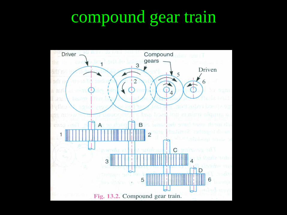
compound gear train
• when there are more than one gear on a shaft is called compound
gear train
Reverted gear train
• When the axes of the first gear and the last gear are co-axial then
the gear train is known as reverted gear train.
Epicyclic gear train
• The axes of the shafts over which the gears are mounted, may
move relative to a fixed axis.

Simple gear train
compound gear train

Reverted gear train

Epicyclic gear train
Epicyclic gear train
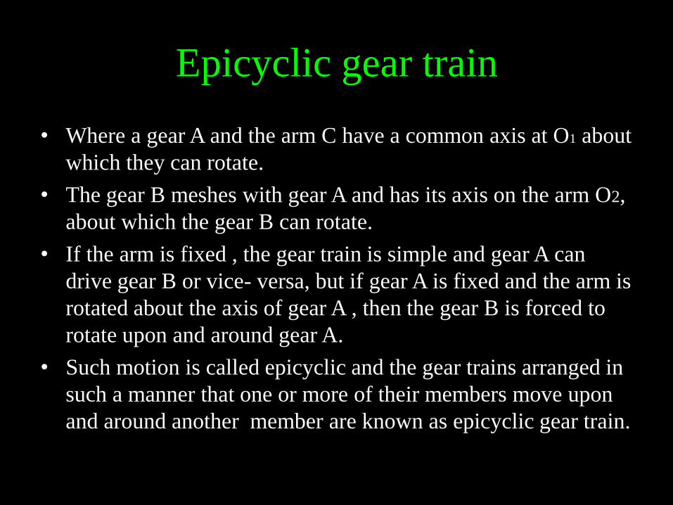
• Where a gear A and the arm C have a common axis at O1 about
which they can rotate.
• The gear B meshes with gear A and has its axis on the arm O2,
about which the gear B can rotate.
• If the arm is fixed , the gear train is simple and gear A can
drive gear B or vice- versa, but if gear A is fixed and the arm is
rotated about the axis of gear A , then the gear B is forced to
rotate upon and around gear A.
• Such motion is called epicyclic and the gear trains arranged in
such a manner that one or more of their members move upon
and around another member are known as epicyclic gear train.

Advantages of epicyclic gear
• Planetary gears are in constant mesh so that neither dog- clutches
nor sliding gears with (or) without synchromesh devices are
employed.
• Gear ratio changes are made with either external contracting band
brakes (or) multi- plate clutches of relatively small dimensions.
• The load on the gears is distributed over several gear wheels,
instead of only a pair of gears.
• The epicyclic gear train can be made smaller in the overall
dimensions than for the 3 (or) 4 speed gear box gears and gear
housing.
• As the epicyclic gears work within an annulus (or) ring gear with
its external surface of cylindrical form, a more compact unit is
obtained, which operates about a common central axis.


Automobile epicyclic gear


Wilson gear box

construction • The gearbox comprises of three subassemblies, the running
gear, the brake harness and the control mechanism housed in an oil tight container.
• This consists of a four epicyclic trains of gear inter connected, so that different ratios and a reverse can be obtained.
• The direct drive is achieved by engaging the clutch.
• One train of epicyclic gearing is used for all the various ratios, its sun S1 being secured to a shaft D coupled permanently to the engine and its arm R1 to the shaft E which is coupled permanently to the driving road wheels and the various ratios are obtained by driving the annulus A1 at different speeds in relation to the engine speed

FIRST GEAR
• First gear is obtained by applying a brake to the first gear
train annulus A1. So that it is held stationary.
• The engine will then, be turning the sun gear S1. So that the planet
gears will be rolling round inside the annulus A1 carrying their
arm R1 round with them.
• As this arm R1 fixed to the output shaft its motion I imported to it.
• If A1 – fixed , S1 – driving, R1 – driven Where S1= 25 teeth
A1= 100 teeth
First Gear ratio:
• Engine speed = 1000 rpm = sun S1 speed
• Arm R1 speed = wheel speed = 1000 x S1/ (A1 +S1)
= 1000 x 25 / (100 + 25) = 1000 x1/5
= 200
• Gear ratio: Driving/ Driven =1000: 200 = 5: 1

SECOND GEAR • Second gear is obtained by holding the second gear train
annulus A2 stationary by its brake.
• The main sun gear S2 still turned by the engine cause the
planet gear to revolve and their arm R2.
• But this arm R2 is connected to the first gear train annulus
A1 which therefore turns, speeding up the rotation of the planet
gear and arm R1 and it turning the output shaft faster than was
the case in first gear, i.e. less reduction.
• Second Gear ratio:
• Engine speed = 1000 rpm = sun gear S1
• Annulus speed = 100 rpm
• Arm R1 speed = wheel speed = 1000 x 1/5 + (100 – ( 100 x 1/5)
= 280 rpm
• Gear ratio: Driving/ Driven =1000: 280 = 3.57: 1

Third gear

THIRD GEAR
• Third gear is obtained by holding the third gear sun wheel S3 by
brake drum holding. Which is interconnected further the annulus
A3 is an integral part of the second gear planet arm R2 which is in
turn connected to the first gear annulus A1.
• The third gear arm R3 is connected to the second gear
annulus A2 so driving it in same direction as the engine. i.e.
increasing its speed so the drive is taken back through the second
gear planets and arm R2 and the first gear train annulus A1 both of
which are speeded up.
• The result is to speed up the first gear train arm R1 which
are connected to output shaft.
• In other words by interconnecting the second and third arms,
an increase of speed is obtained at the first gear train annulus,
which increases the speed of the arm R1.

Third Gear ratio
• Engine speed = 1000 rpm = sun gear S1
• Annulus speed = 200 rpm
• Arm R1 speed = wheel speed = 1000 x 1/5 + (200 – ( 200 x 1/5)
= 360 rpm
• Gear ratio: Driving/ Driven =1000: 360 = 2.78: 1
Reversed Gear ratio
• Engine speed = 1000 rpm = sun gear S1
• Annulus speed = – 400 rpm
• Arm R1 speed = wheel speed = 1000 x 1/5 +(– 400 – (– 400 x
1/5)
= –120 rpm


Cotal Electro Magnetically operated planetary gear box

Explanation • The transmission employs four magnetic clutches.
• Clutch 1 being secured to driving pinion A1 & clutch 4 to driven
shaft B.
• 2 & 3 are secured to transmission housing.
• Between 1 & 2 there is an armature C. It has ring gear R2 with a dual
planet pinions.
• 1 is energized then R2 is rotated by A1.
• Energizing clutch 2 the ring gear is held from rotation.
• Since sun gear is rigidly secured to driving pinion A1, when clutch 1
is energized the planetary train is locked & power is transmitted
through it directly.
• When 2 is energized then power is transmitted from A1 to planet
carrier A2 at reduced speed.
• Carrier A2 is secured to carrier A3.
• Sun S3 of this second train is secured to armature H.

Contd…
• H can be held by clutch 3 (or) rotated by clutch 4.
• When held stationary, planetary train is active, and gives increased
speed since planet carrier is driver & ring gear is driven.
• When it is locked, motion is transmitted directly.
• Thus two trains – each with 2 ratios – each ratio can combine with
either ratio – total of 4 ratios.
• 1st speed clutches 2 & 4 energized. Reduction ratio 2.17 in first
train & direct drive in rear train.
• 2nd speed clutches 2 & 3 . Step down of 2.17 from first and step up
of 0.72 from second.
• Over all ratio is 2.17 x 0.72 = 1.56.
• Direct drive – clutches 1 & 4 energized – both trains locked.
• When 1 & 3 energized, forward train is locked and rear function –
over drive of 0.72 : 1.
• Reverse gear is at the forward end of gear box.

Hydraulic control system for automatic transmission

Explanation
• The hydraulic control system of the automatic transmission is
shown in figure. Which is a simplified diagram illustrating
the basic principles.
• Hydraulic fluid is drawn from input and ensures that pressure is
available as soon as the engine starts.
• The rear pump is driven from the output shaft so that pressure
is generated in this pump as soon as the vehicle moves, and
this feature provides a means of preventing the reverse and
park mechanisms being engaged whilst the vehicle is in motion.
• Non-return valves ensure that hydraulic pressure can be
available from either pump and the joint delivery is regulated
to a suitable pressure by a pressure relief valve.
• The fluid at regulated pressure is fed to the converter which
is kept full of fluid and a small flow from the converter is
used for lubrication of the gearbox

Contd….
• The main fluid supply is fed to the manual selector valve
which is controlled by a steering-column selector lever, and this
may be moved to any of five positions.
• This valve may direct fluid under pressure to the reverse
brake when a reverse ratio is obtained. In the low selection, fluid is
applied to both the forward and low brakes and maintains the
transmission in low gear.
• Neutral selection is obtained by removal of pressure from all
friction elements, and the park position engages a mechanical
lock preventing rotation of the output shaft.
• When the Drive selection is made the manual selector applies fluid under pressure to the Forward and Low brakes and also to the governor valve.
• The governor valve is moved by the combination of an accelerator pedal movement together with the position of a centrifugal governor.

Contd…
• At low road speeds the governor valve is blocked and the
transmission is retained in low gear.
• At a higher road speed the governor valve moves to apply
fluid at pressure to the multi-plate clutch so as to engage
Intermediate gear.
• As the multi-plate clutch begins to take up the drive the
pressure in the clutch rises and becomes sufficient to operate
the relay valve and cut off the fluid supply to the low friction
brake band.
• This relay valve carries out the transition from Low to
Intermediate clutch.
• This relay valve corresponds to the more usual shift although
in this case the valve is moved by spring force in opposition to
hydraulic pressure.

Contd… • The change into direct drive is effected by the application
of fluid pressure to the single-plate clutch by the governor
valve.
• The other friction elements remain in the same condition
as for the Intermediate gear so that no transition from one
element to another is needed.
• No smoothing device is incorporated for the take-up of this
clutch, which relies on the capacity of the clutch piston to
give a steady build-up of pressure.
• Gear changes to lower ratios operate in the reverse
sequence.

FORD T-MODEL

Working FORT T - MODEL • An example of the “all-spur” type of planetary transmission is
the ford model T, with which millions of cars have been
equipped.
• A sectional view of this transmission is shown in figure.
• Here, instead of power being applied through one of the sun
pinions, it is applied to the planet carrier.
• The flywheel rim A serves as planet carrier and driving
member, having lateral studs secured into it which carry triple
planetary pinions.
• Gear B is the driven member, being keyed to the hub of clutch
drum C, which in turn is secured to driven shaft D.
• By applying a brake band to drum E, gear F is held stationary,
pinion G rolls on it, and the smaller pinion H causes gear B to
turn slowly in the same direction as pinion carrier A.

Contd…
• By applying a brake band to drum I, gear J is held stationary;
pinion H turns gear B slowly in the reverse direction.
• For the high gear or direct drive, the friction clutch locks clutch
drum C to the engine crankshaft, and the gear rotates as a unit.
• The three pedals control the transmission and brakes. When
the left pedal is push down all the way, the car is low gear.
• To remain in low gear, you must continue pushing on the left
pedal. (It’s been said that you push a Model T up a hill in low
gear with your left foot!).
• If the left pedal is pushed to the halfway position, the car is in
neutral.
• When the left pedal is completely released (not depressed at
all) , the car is in high gear.

Contd…
• If the car is in neutral (either by depressing the left pedal
halfway or by moving the lever to the left of the pedals to an
upright position) the middle pedal can be pushed to engage
reverse gear.
• The right pedal is a brake that acts on the transmission
when pushed. Operating the brake and transmission sounds
more difficult.
• After some practice, most drivers don’t give it a second
thought.
• Interestingly, the Model T has a planetary transmission
that’s the forerunner of the transmission. It’s very similar to an
automatic transmission expect you use foot pedal pressure to
operate the bands rather then hydraulic pressure and it doesn’t
have a torque converter.

Contd… • The lever at the right and under the steering wheel is the hand
throttle. It controls the speed, much like the control found on the
tractor or riding mover.
• Model T’s were made from 1908 until 1927. Over 15 million
Model T’s were produced.
• Far more were produced than any other car until the
Volkswagen Beetle overtook its production in the 1970’s, at a time
when two- car families become the norm.
• The impact of the Model T’s in its day is hard far us to imagine,
but in the early 1920s, half of all cars on the road worldwide
were Model T’s.
• A Model T in good mechanical condition will cruise all day at 30 to
35 mph. Most can go 45 to 50 mph but the engine is working pretty
hard at these speeds, so most drivers go this fast only briefly.