Unit III- Medium Access Control
142
Unit III- Medium Access Control Note: Material for this presentations are taken from Internet and books and only being used for students reference and not for commercial purpose
Transcript of Unit III- Medium Access Control
Unit III- Medium Access Control
Note: Material for this presentations are taken from Internet and books and only being used for students reference and not for commercial purpose
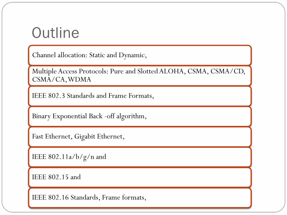
Outline
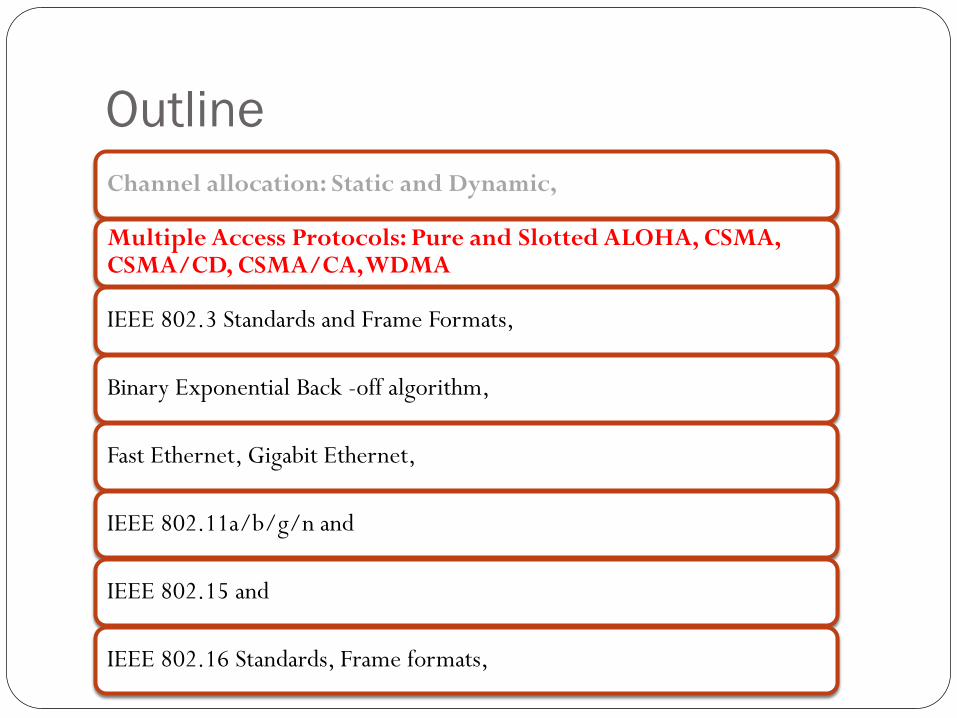
Channel allocation: Static and Dynamic,
Multiple Access Protocols: Pure and Slotted ALOHA, CSMA, CSMA/CD, CSMA/CA, WDMA
IEEE 802.3 Standards and Frame Formats,
Binary Exponential Back -off algorithm,
Fast Ethernet, Gigabit Ethernet,
IEEE 802.11a/b/g/n and
IEEE 802.15 and
IEEE 802.16 Standards, Frame formats,
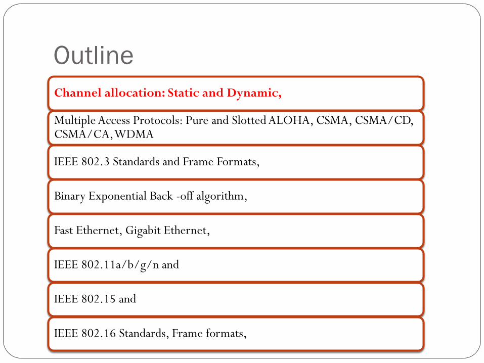
Outline
Channel allocation: Static and Dynamic,
Multiple Access Protocols: Pure and Slotted ALOHA, CSMA, CSMA/CD, CSMA/CA, WDMA
IEEE 802.3 Standards and Frame Formats,
Binary Exponential Back -off algorithm,
Fast Ethernet, Gigabit Ethernet,
IEEE 802.11a/b/g/n and
IEEE 802.15 and
IEEE 802.16 Standards, Frame formats,
Multiple access protocols
In LANs, Wi-Fi, satellite networks the access to the shared
media should be controlled.
If more than 2 nodes send at the same time →collision
All collided packets are lost → waste of bandwidth
Ideally, the MAC protocol for a broadcast channel with the
bit-rate R bps should satisfy:
if only 1 node is sending than the throughput is R
when M nodes have data to send than the throughput is R/M
decentralized protocol – no master
simple & inexpensive to implement
The Channel Allocation Problem
5
To allocate a single broadcast channel among competing users,
we can use:
• Static Channel Allocation in LANs and MANs
• Dynamic Channel Allocation in LANs and MANs
Static Channel Allocation in LANs and MANs
6
Frequency Division Multiplexing (FDM) is an example of static channel allocation where the bandwidth is divided among a number of N users.
When there is only a small and constant number of users, each of which has a heavy (buffered) load of traffic (e.g., carriers' switching offices), FDM is a simple and efficient allocation mechanism.
However, when the number of senders is large and continuously varying or the traffic is bursty, FDM presents some problems.
• 1) when fewer than N users are currently interested in communicating, a large piece of valuable spectrum will be wasted.
• 2) when more users wants to communicate, those who have not been assigned a frequency will be denied permission.
• 3) even assuming that the number of users could somehow be held constant at N, each user traffic usually changes dynamically over time.
Dynamic Channel Allocation in LANs and MANs
7
Station Model: N independent stations (terminals) exists.
Single Channel Assumption: A single channel is available for all communication (send and receive)
Collision Assumption: If two frames are transmitted simultaneously, they overlap in time and the resulting signal is garbled (collision). no errors other than those generated by collisions assumed to exist.
(a) Continuous Time: Frame transmission can begin at any instant. (b) Slotted Time: Frame transmissions always begin at the start of a slot where the time is divided into discrete slots.
(a) Carrier Sense: Stations can tell if the channel is in use before trying to use it. (b) No Carrier Sense: Stations cannot sense the channel before trying to use it.
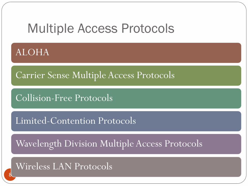
Multiple Access Protocols
8
ALOHA
Carrier Sense Multiple Access Protocols
Collision-Free Protocols
Limited-Contention Protocols
Wavelength Division Multiple Access Protocols
Wireless LAN Protocols
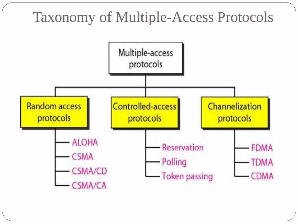
Taxonomy of Multiple-Access Protocols
Outline
Channel allocation: Static and Dynamic,
Multiple Access Protocols: Pure and Slotted ALOHA, CSMA, CSMA/CD, CSMA/CA, WDMA
IEEE 802.3 Standards and Frame Formats,
Binary Exponential Back -off algorithm,
Fast Ethernet, Gigabit Ethernet,
IEEE 802.11a/b/g/n and
IEEE 802.15 and
IEEE 802.16 Standards, Frame formats,
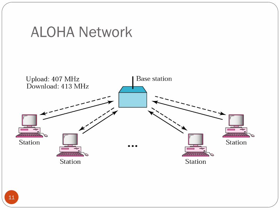
ALOHA Network
11
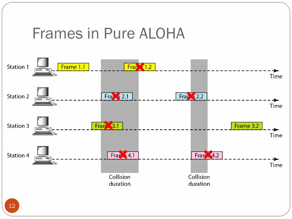
Frames in Pure ALOHA
12
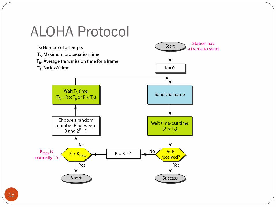
ALOHA Protocol
13
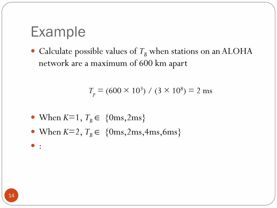
Example
14
Calculate possible values of TB when stations on an ALOHA
network are a maximum of 600 km apart
Tp = (600 × 103) / (3 × 10⁸) = 2 ms
When K=1, TB {0ms,2ms}
When K=2, TB {0ms,2ms,4ms,6ms}
:
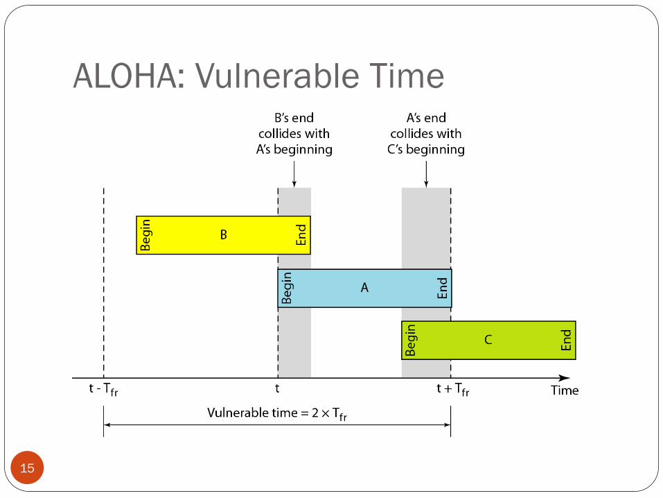
ALOHA: Vulnerable Time
15
ALOHA: Throughput
16
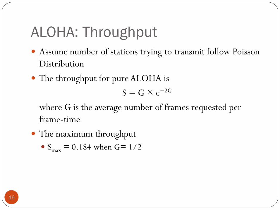
Assume number of stations trying to transmit follow Poisson
Distribution
The throughput for pure ALOHA is
S = G × e−2G
where G is the average number of frames requested per
frame-time
The maximum throughput
Smax = 0.184 when G= 1/2
Example
17
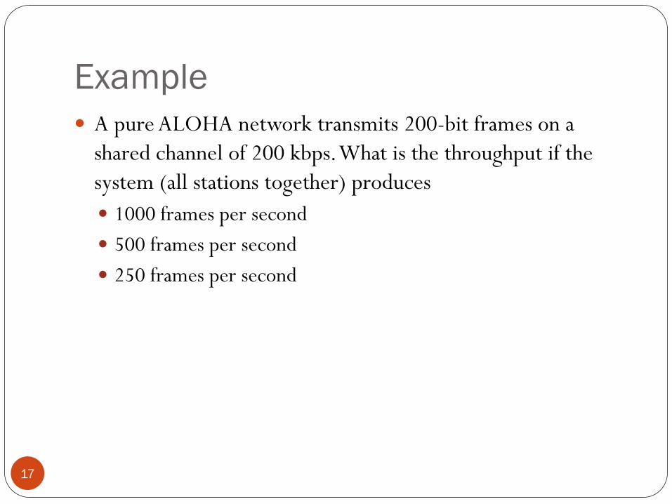
A pure ALOHA network transmits 200-bit frames on a
shared channel of 200 kbps. What is the throughput if the
system (all stations together) produces
1000 frames per second
500 frames per second
250 frames per second
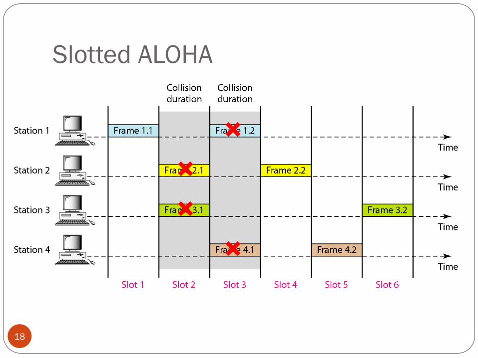
Slotted ALOHA
18
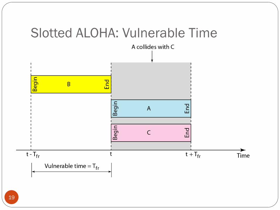
Slotted ALOHA: Vulnerable Time
19
Slotted ALOHA: Throughput
20
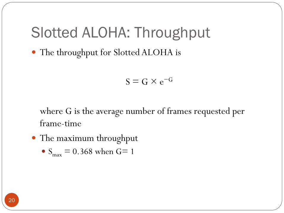
The throughput for Slotted ALOHA is
S = G × e−G
where G is the average number of frames requested per
frame-time
The maximum throughput
Smax = 0.368 when G= 1
Example
21
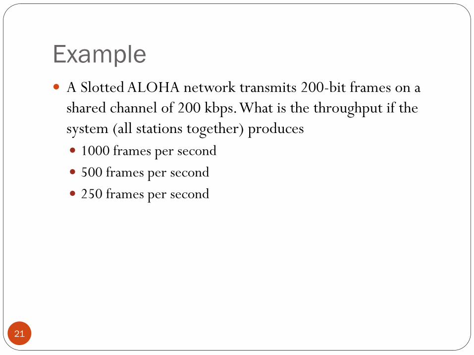
A Slotted ALOHA network transmits 200-bit frames on a
shared channel of 200 kbps. What is the throughput if the
system (all stations together) produces
1000 frames per second
500 frames per second
250 frames per second
CSMA
22
Carrier Sense Multiple Access
"Listen before talk"
Reduce the possibility of collision
But cannot completely eliminate it
Persistence Methods
23
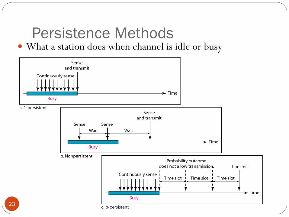
What a station does when channel is idle or busy
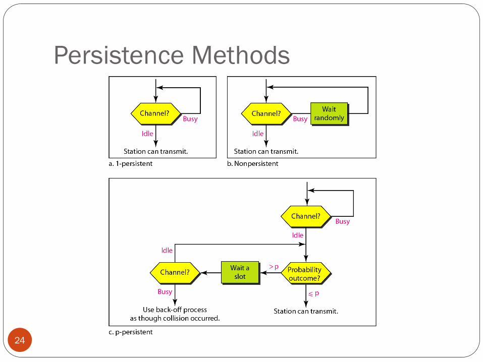
Persistence Methods
24
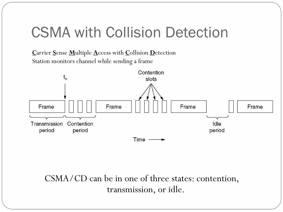
CSMA with Collision Detection
CSMA/CD can be in one of three states: contention, transmission, or idle.
Carrier Sense Multiple Access with Collision Detection
Station monitors channel while sending a frame
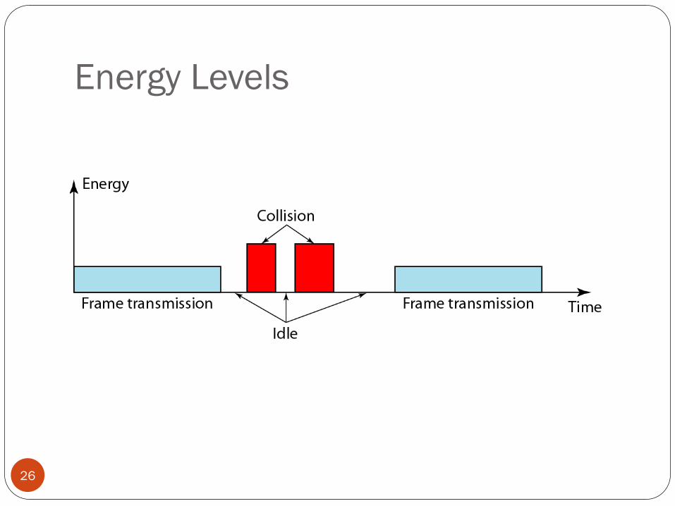
Energy Levels
26
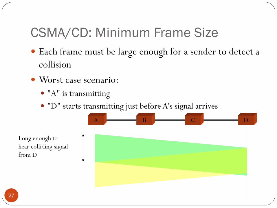
CSMA/CD: Minimum Frame Size
27
Each frame must be large enough for a sender to detect a
collision
Worst case scenario:
"A" is transmitting
"D" starts transmitting just before A's signal arrives
A B C D
Long enough to
hear colliding signal
from D
Example
28
A CSMA/CD network has a bandwidth of 10 Mbps. If the
maximum propagation time is 25.6 μs, what is the minimum
size of the frame?
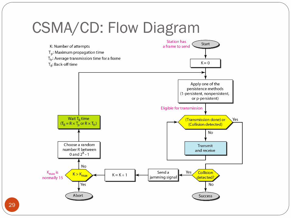
CSMA/CD: Flow Diagram
29
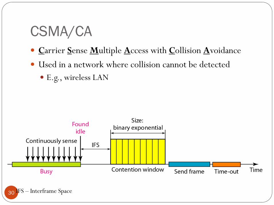
CSMA/CA
30
Carrier Sense Multiple Access with Collision Avoidance
Used in a network where collision cannot be detected
E.g., wireless LAN
IFS – Interframe Space
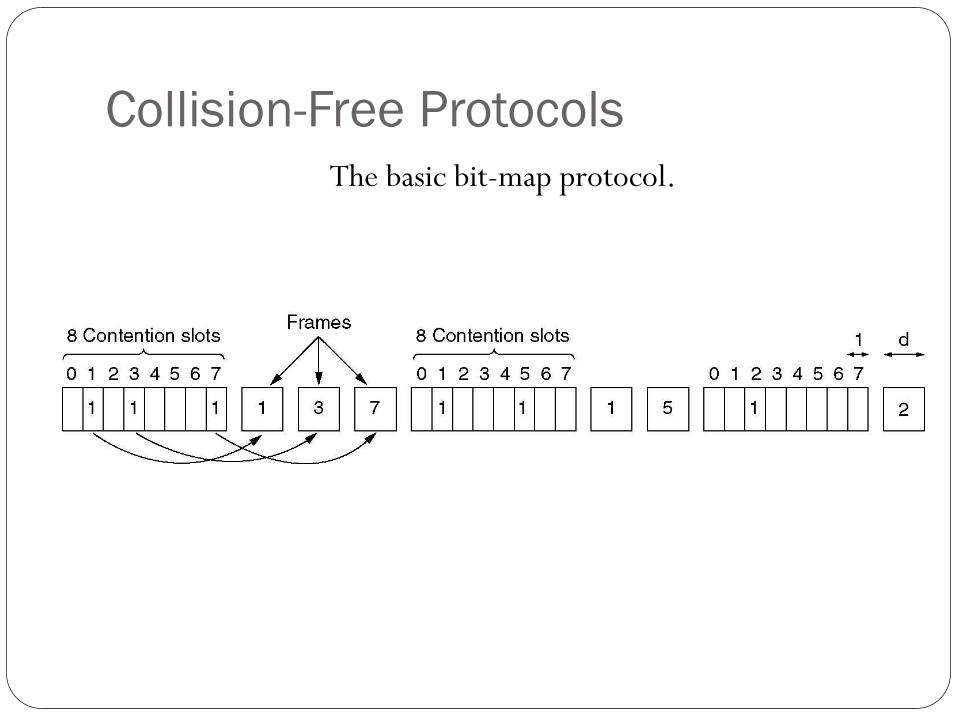
Collision-Free Protocols
The basic bit-map protocol.
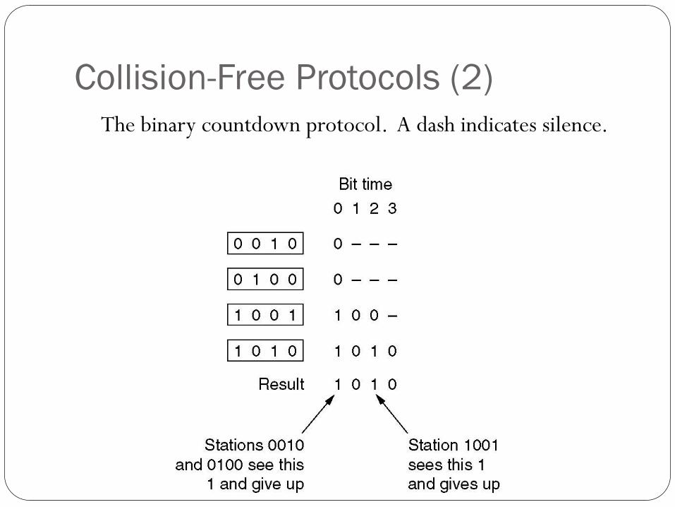
Collision-Free Protocols (2)
The binary countdown protocol. A dash indicates silence.
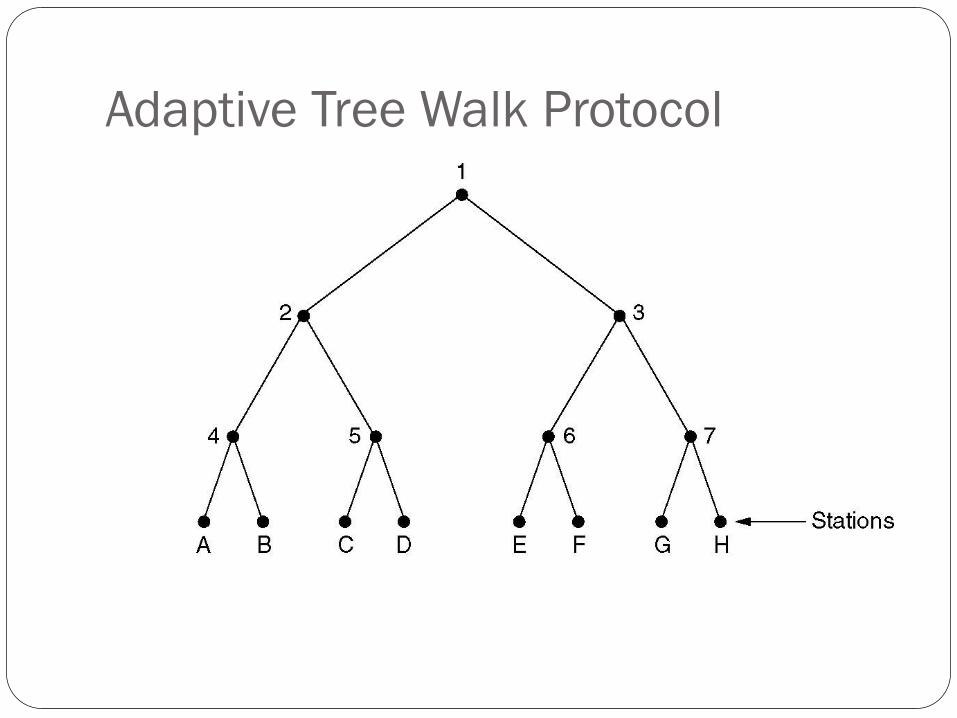
Adaptive Tree Walk Protocol
The tree for eight stations.
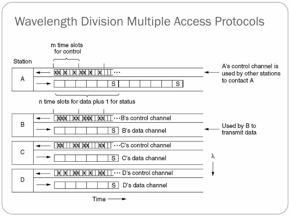
Wavelength Division Multiple Access Protocols
Wavelength division multiple access.
Outline
Channel allocation: Static and Dynamic,
Multiple Access Protocols: Pure and Slotted ALOHA, CSMA, CSMA/CD, CSMA/CA, WDMA
IEEE 802.3 Standards and Frame Formats,
Binary Exponential Back -off algorithm,
Fast Ethernet, Gigabit Ethernet,
IEEE 802.11a/b/g/n and
IEEE 802.15 and
IEEE 802.16 Standards, Frame formats,
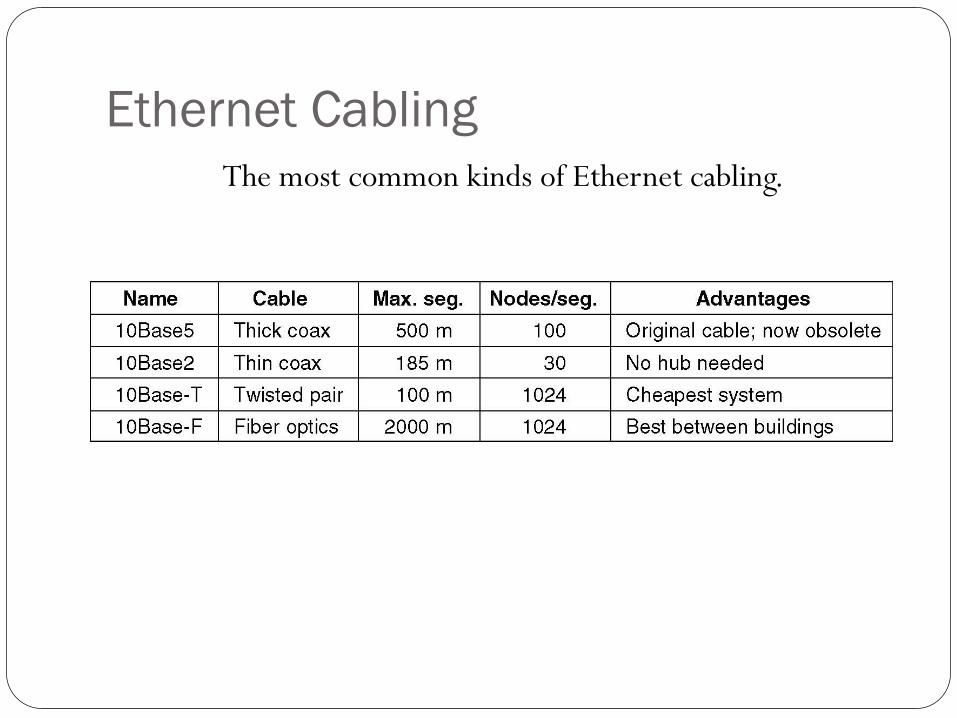
Ethernet Cabling
The most common kinds of Ethernet cabling.
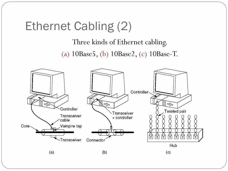
Ethernet Cabling (2)
Three kinds of Ethernet cabling.
(a) 10Base5, (b) 10Base2, (c) 10Base-T.
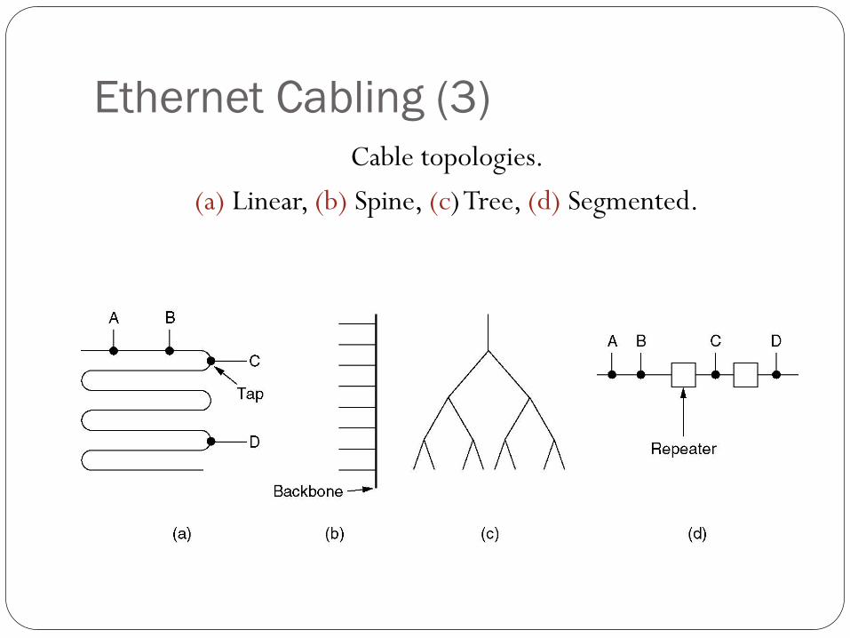
Ethernet Cabling (3)
Cable topologies.
(a) Linear, (b) Spine, (c) Tree, (d) Segmented.
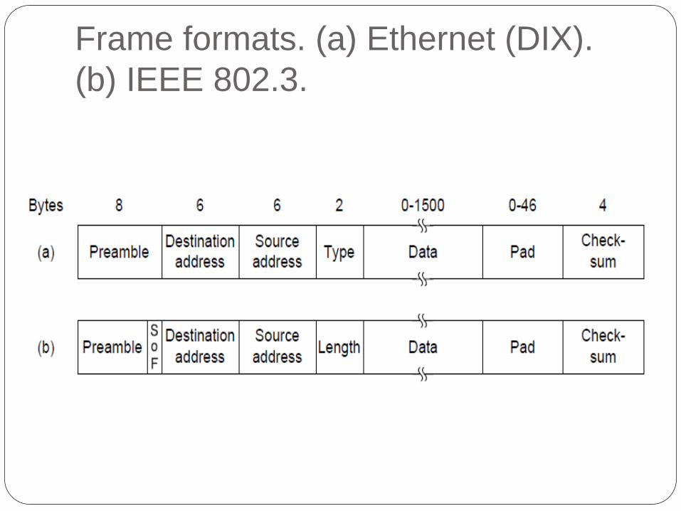
Frame formats. (a) Ethernet (DIX).
(b) IEEE 802.3.
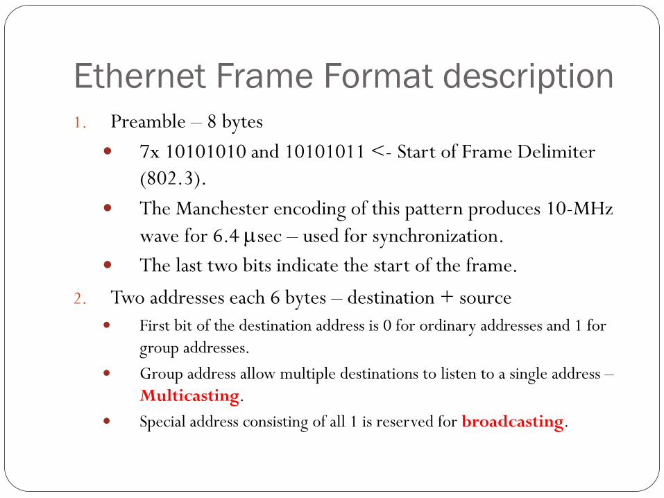
Ethernet Frame Format description 1. Preamble – 8 bytes
7x 10101010 and 10101011 <- Start of Frame Delimiter
(802.3).
The Manchester encoding of this pattern produces 10-MHz
wave for 6.4 msec – used for synchronization.
The last two bits indicate the start of the frame.
2. Two addresses each 6 bytes – destination + source
First bit of the destination address is 0 for ordinary addresses and 1 for
group addresses.
Group address allow multiple destinations to listen to a single address –
Multicasting.
Special address consisting of all 1 is reserved for broadcasting.
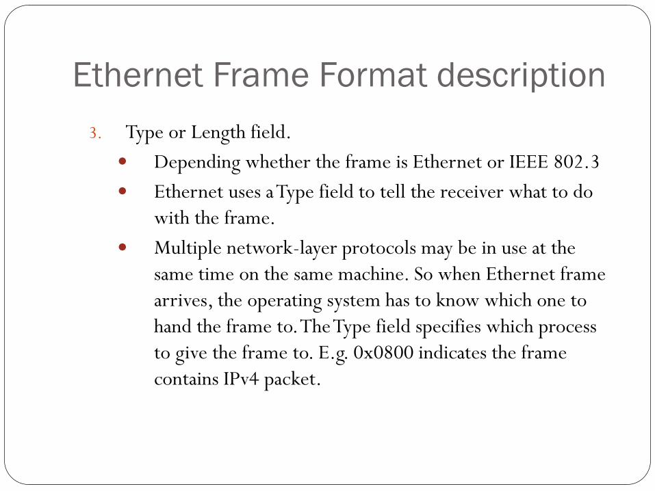
Ethernet Frame Format description
3. Type or Length field.
Depending whether the frame is Ethernet or IEEE 802.3
Ethernet uses a Type field to tell the receiver what to do
with the frame.
Multiple network-layer protocols may be in use at the
same time on the same machine. So when Ethernet frame
arrives, the operating system has to know which one to
hand the frame to. The Type field specifies which process
to give the frame to. E.g. 0x0800 indicates the frame
contains IPv4 packet.
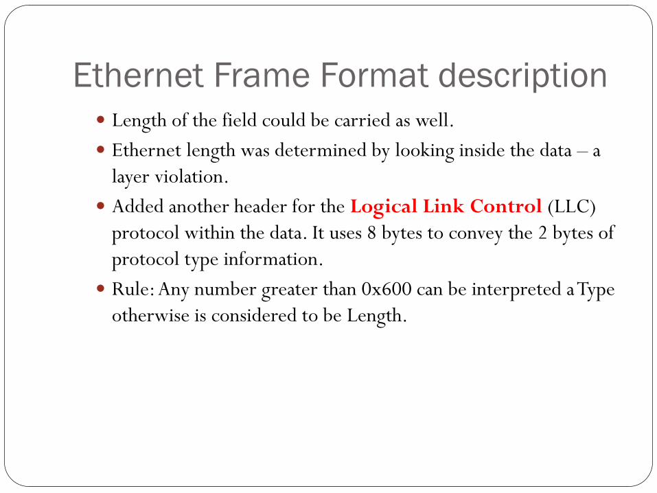
Ethernet Frame Format description Length of the field could be carried as well.
Ethernet length was determined by looking inside the data – a
layer violation.
Added another header for the Logical Link Control (LLC)
protocol within the data. It uses 8 bytes to convey the 2 bytes of
protocol type information.
Rule: Any number greater than 0x600 can be interpreted a Type
otherwise is considered to be Length.
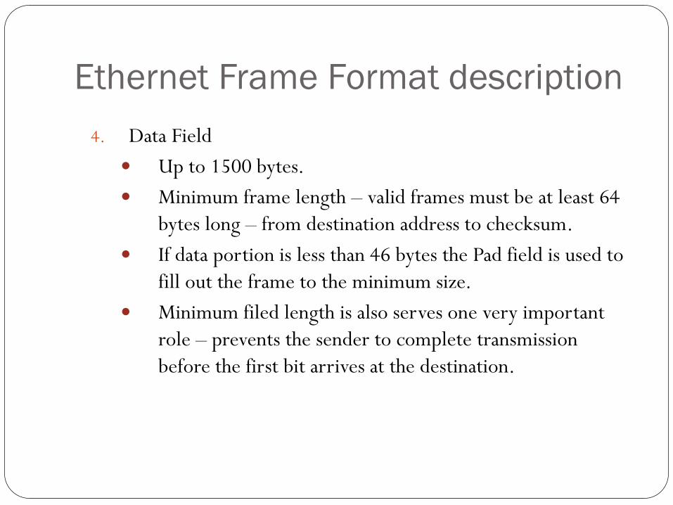
Ethernet Frame Format description
4. Data Field
Up to 1500 bytes.
Minimum frame length – valid frames must be at least 64
bytes long – from destination address to checksum.
If data portion is less than 46 bytes the Pad field is used to
fill out the frame to the minimum size.
Minimum filed length is also serves one very important
role – prevents the sender to complete transmission
before the first bit arrives at the destination.
Outline
Channel allocation: Static and Dynamic,
Multiple Access Protocols: Pure and Slotted ALOHA, CSMA, CSMA/CD, CSMA/CA, WDMA
IEEE 802.3 Standards and Frame Formats,
Binary Exponential Back -off algorithm,
Fast Ethernet, Gigabit Ethernet,
IEEE 802.11a/b/g/n and
IEEE 802.15 and
IEEE 802.16 Standards, Frame formats,
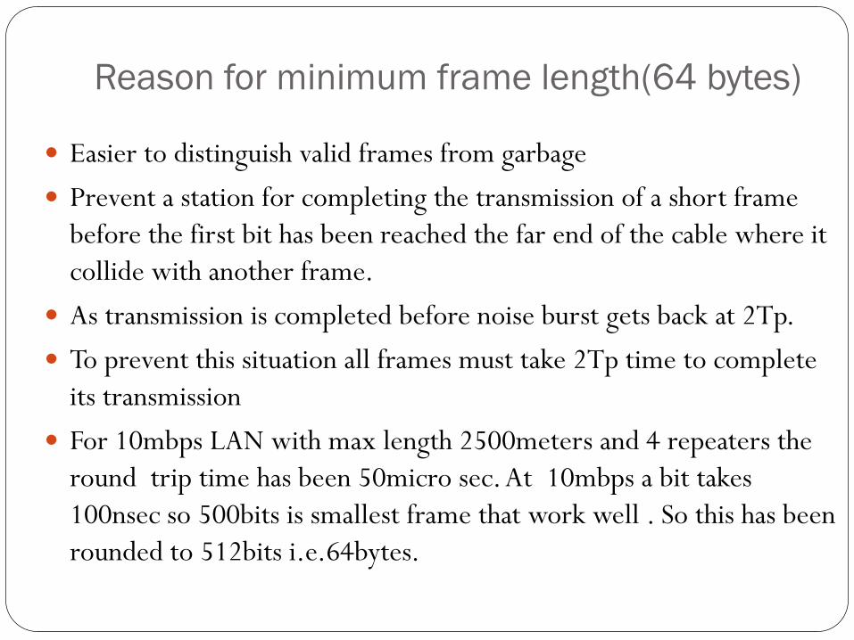
Reason for minimum frame length(64 bytes)
Easier to distinguish valid frames from garbage
Prevent a station for completing the transmission of a short frame
before the first bit has been reached the far end of the cable where it
collide with another frame.
As transmission is completed before noise burst gets back at 2Tp.
To prevent this situation all frames must take 2Tp time to complete
its transmission
For 10mbps LAN with max length 2500meters and 4 repeaters the
round trip time has been 50micro sec. At 10mbps a bit takes
100nsec so 500bits is smallest frame that work well . So this has been
rounded to 512bits i.e.64bytes.
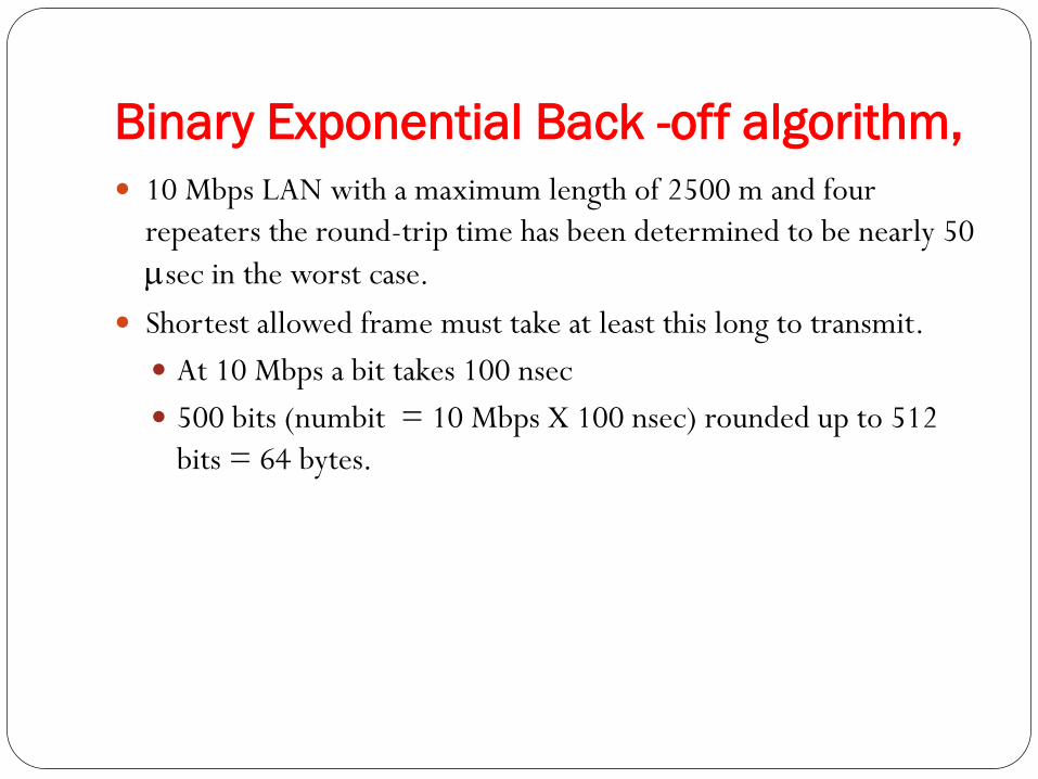
Binary Exponential Back -off algorithm,
10 Mbps LAN with a maximum length of 2500 m and four
repeaters the round-trip time has been determined to be nearly 50
msec in the worst case.
Shortest allowed frame must take at least this long to transmit.
At 10 Mbps a bit takes 100 nsec
500 bits (numbit = 10 Mbps X 100 nsec) rounded up to 512
bits = 64 bytes.
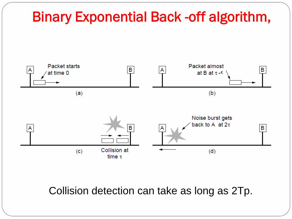
Binary Exponential Back -off algorithm,
Collision detection can take as long as 2Tp.
Binary exponential backoff algo
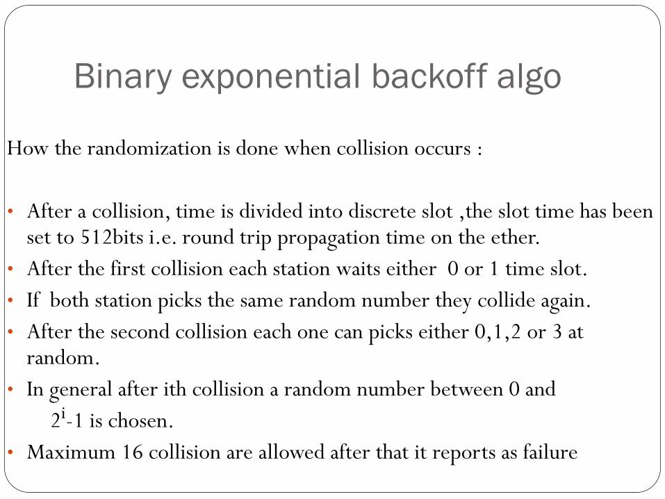
How the randomization is done when collision occurs :
• After a collision, time is divided into discrete slot ,the slot time has been set to 512bits i.e. round trip propagation time on the ether.
• After the first collision each station waits either 0 or 1 time slot.
• If both station picks the same random number they collide again.
• After the second collision each one can picks either 0,1,2 or 3 at random.
• In general after ith collision a random number between 0 and
2i-1 is chosen.
• Maximum 16 collision are allowed after that it reports as failure
Outline
Channel allocation: Static and Dynamic,
Multiple Access Protocols: Pure and Slotted ALOHA, CSMA, CSMA/CD, CSMA/CA, WDMA
IEEE 802.3 Standards and Frame Formats,
Binary Exponential Back -off algorithm,
Fast Ethernet, Gigabit Ethernet,
IEEE 802.11a/b/g/n and
IEEE 802.15 and
IEEE 802.16 Standards, Frame formats,
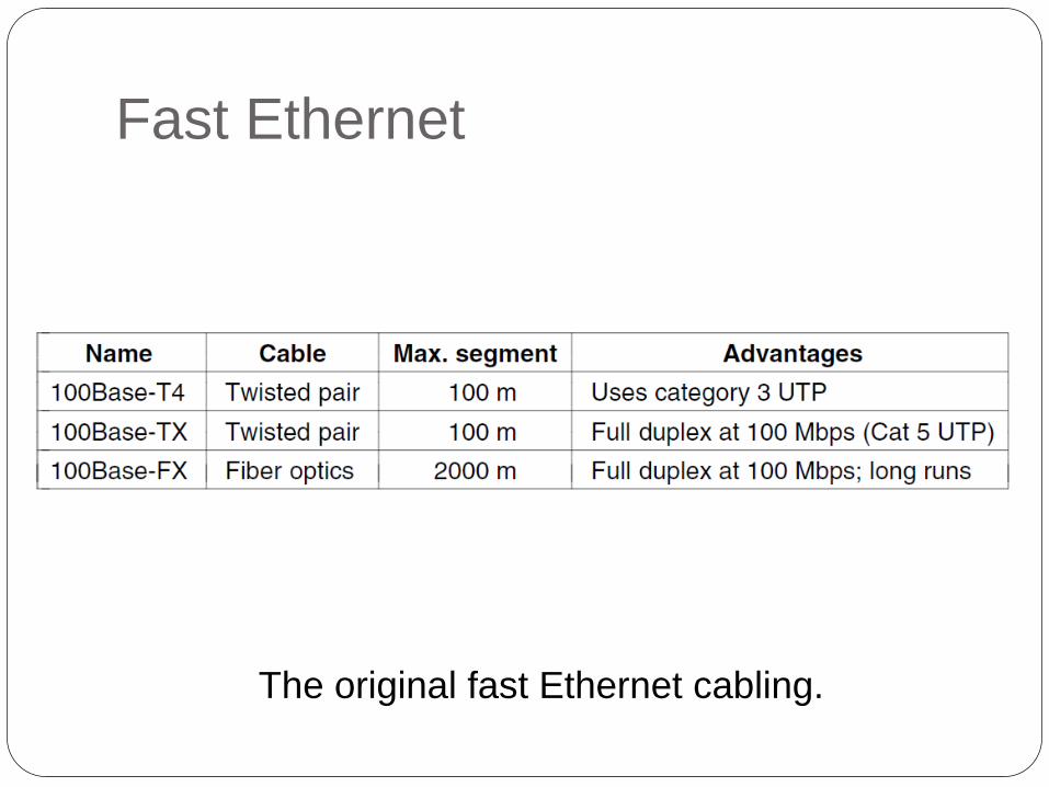
Fast Ethernet
The original fast Ethernet cabling.
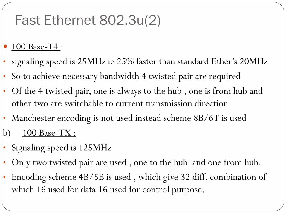
Fast Ethernet 802.3u(2)
100 Base-T4 :
• signaling speed is 25MHz ie 25% faster than standard Ether’s 20MHz
• So to achieve necessary bandwidth 4 twisted pair are required
• Of the 4 twisted pair, one is always to the hub , one is from hub and
other two are switchable to current transmission direction
• Manchester encoding is not used instead scheme 8B/6T is used
b) 100 Base-TX :
• Signaling speed is 125MHz
• Only two twisted pair are used , one to the hub and one from hub.
• Encoding scheme 4B/5B is used , which give 32 diff. combination of
which 16 used for data 16 used for control purpose.
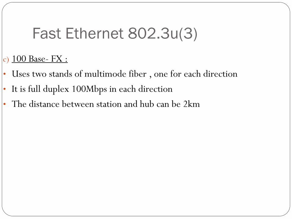
Fast Ethernet 802.3u(3)
c) 100 Base- FX :
• Uses two stands of multimode fiber , one for each direction
• It is full duplex 100Mbps in each direction
• The distance between station and hub can be 2km
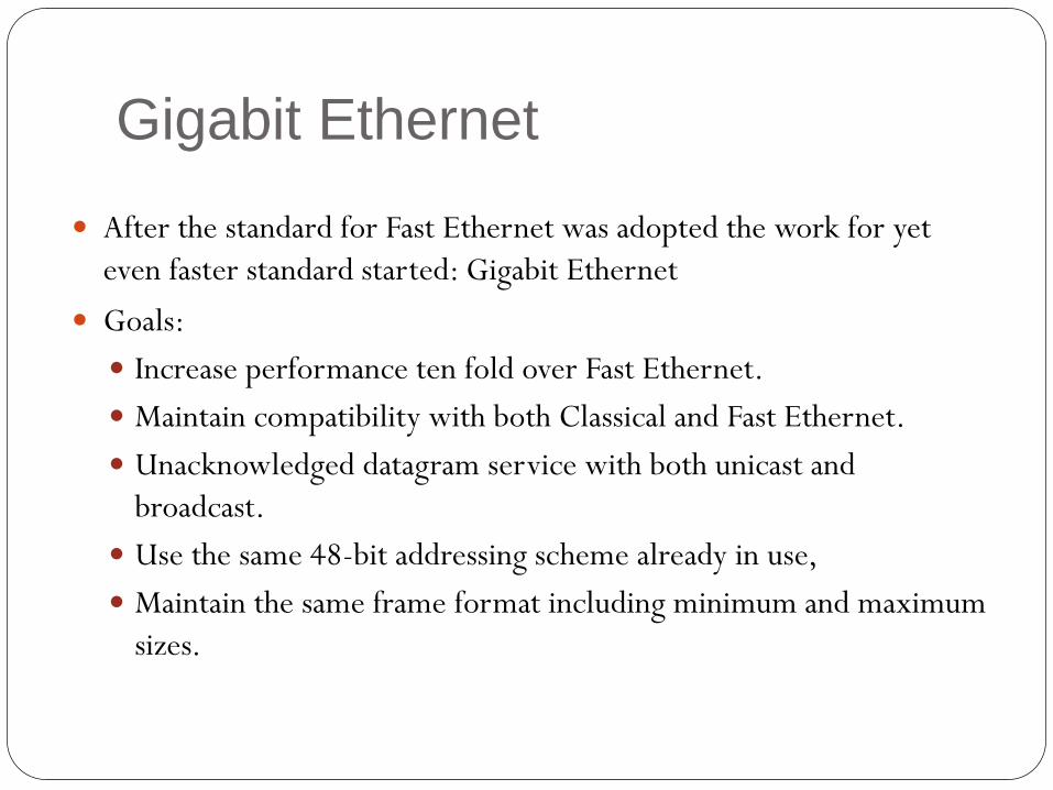
Gigabit Ethernet
After the standard for Fast Ethernet was adopted the work for yet
even faster standard started: Gigabit Ethernet
Goals:
Increase performance ten fold over Fast Ethernet.
Maintain compatibility with both Classical and Fast Ethernet.
Unacknowledged datagram service with both unicast and
broadcast.
Use the same 48-bit addressing scheme already in use,
Maintain the same frame format including minimum and maximum
sizes.
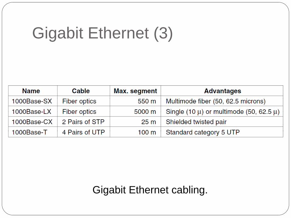
Gigabit Ethernet (3)
Gigabit Ethernet cabling.

Gigabit Ethernet (4)
Gigabit support both copper and fiber cabling
Signaling at 1Gbps over fiber means that light source has to be turned on and off in under 1nsec
LED’s can not operate at this speed so lasers are used
Three fiber diameters are permitted : 10,50 and 62.5 microns
Two wavelengths are permitted : 0.85 and 1.3 microns
On fiber new encoding scheme 8B/10B is used ie each 8bits is encoded as 10 bits on fiber
1024 possible code words for each input is possible so two rules are available to make the decision
1> No codeword have more than 4 identical bits in a row
2> No codeword may have more than six 0s or six 1s
Outline
Channel allocation: Static and Dynamic,
Multiple Access Protocols: Pure and Slotted ALOHA, CSMA, CSMA/CD, CSMA/CA, WDMA
IEEE 802.3 Standards and Frame Formats,
Binary Exponential Back -off algorithm,
Fast Ethernet, Gigabit Ethernet,
IEEE 802.11a/b/g/n
IEEE 802.15 and
IEEE 802.16 Standards, Frame formats,
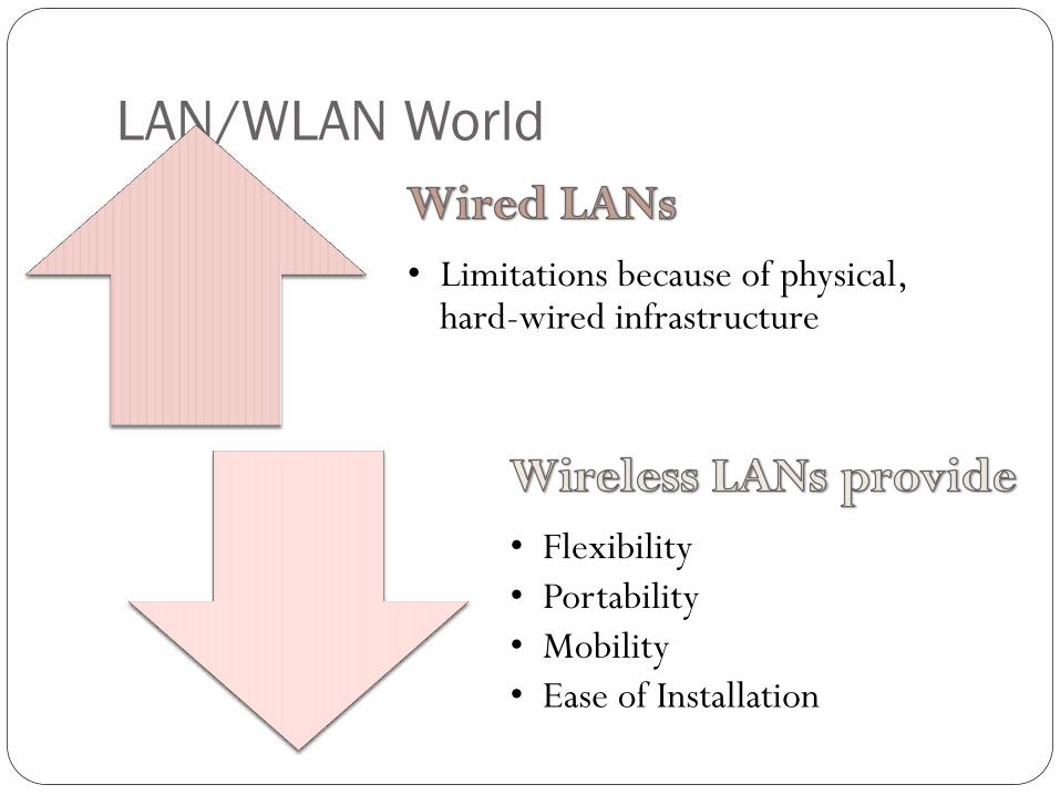
LAN/WLAN World
• Limitations because of physical, hard-wired infrastructure
• Flexibility
• Portability
• Mobility
• Ease of Installation
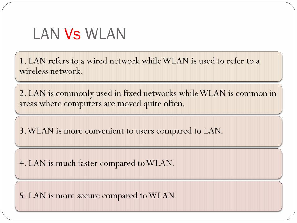
LAN Vs WLAN
1. LAN refers to a wired network while WLAN is used to refer to a wireless network.
2. LAN is commonly used in fixed networks while WLAN is common in areas where computers are moved quite often.
3. WLAN is more convenient to users compared to LAN.
4. LAN is much faster compared to WLAN.
5. LAN is more secure compared to WLAN.
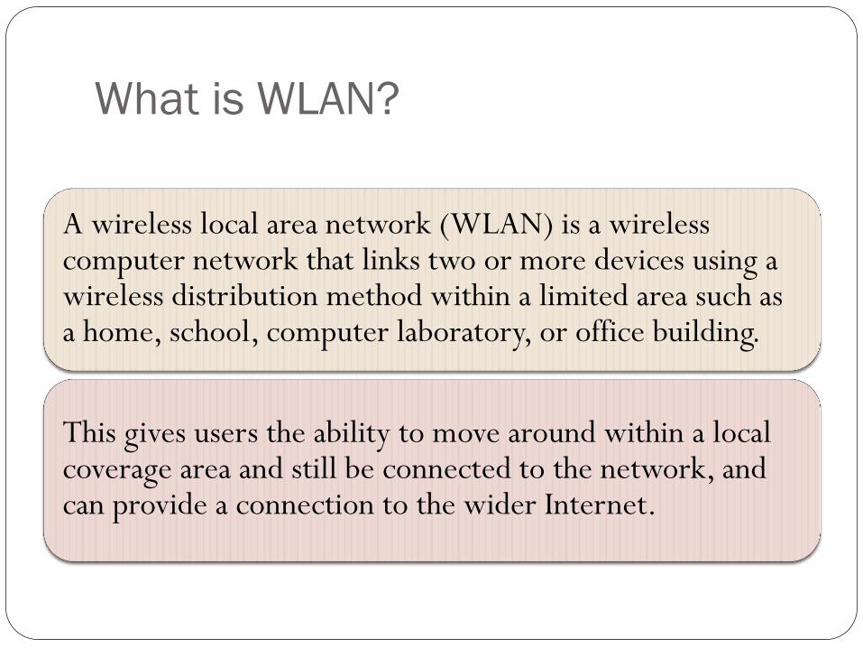
What is WLAN?
A wireless local area network (WLAN) is a wireless computer network that links two or more devices using a wireless distribution method within a limited area such as a home, school, computer laboratory, or office building.
This gives users the ability to move around within a local coverage area and still be connected to the network, and can provide a connection to the wider Internet.
AP AP
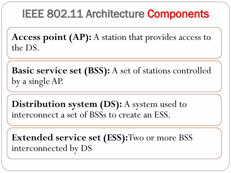
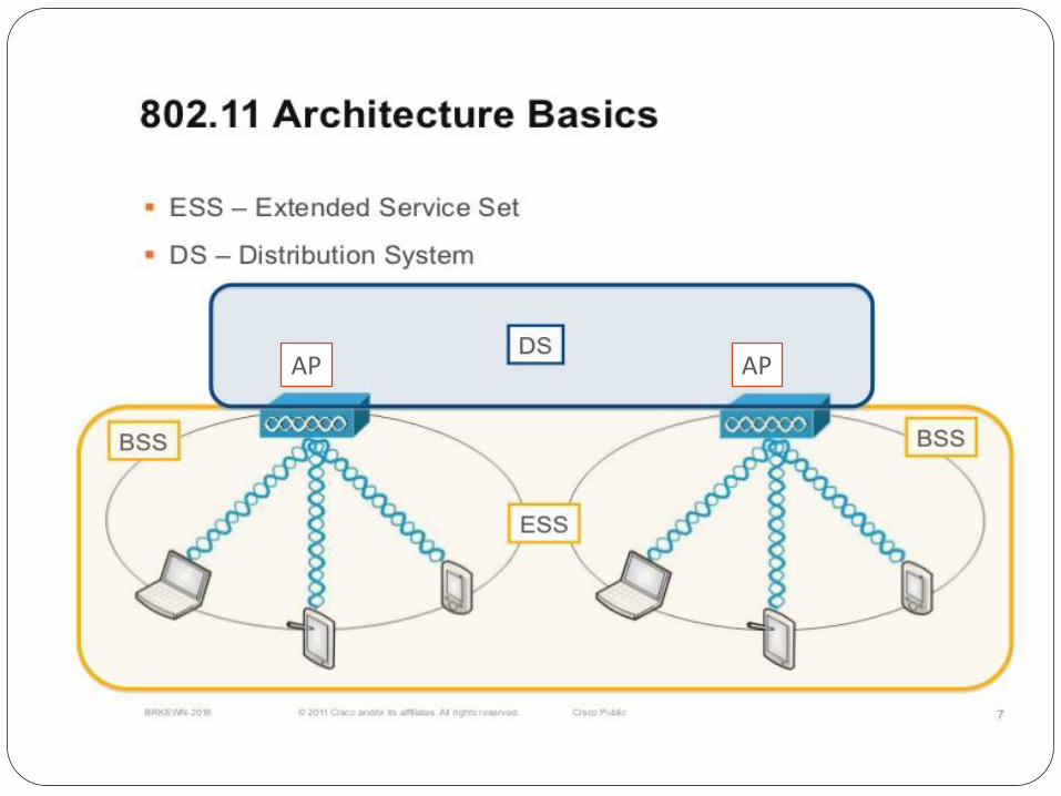
IEEE 802.11 Architecture Components
Access point (AP): A station that provides access to the DS.
Basic service set (BSS): A set of stations controlled by a single AP.
Distribution system (DS): A system used to interconnect a set of BSSs to create an ESS.
Extended service set (ESS):Two or more BSS interconnected by DS
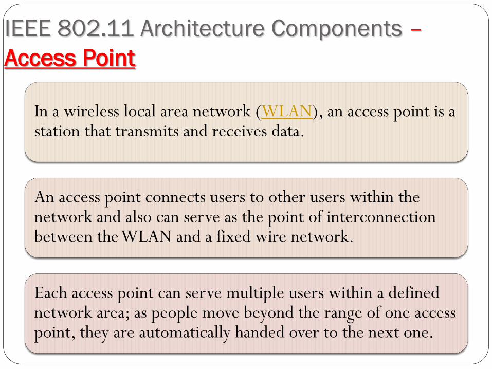
IEEE 802.11 Architecture Components –
Access Point
In a wireless local area network (WLAN), an access point is a station that transmits and receives data.
An access point connects users to other users within the network and also can serve as the point of interconnection between the WLAN and a fixed wire network.
Each access point can serve multiple users within a defined network area; as people move beyond the range of one access point, they are automatically handed over to the next one.
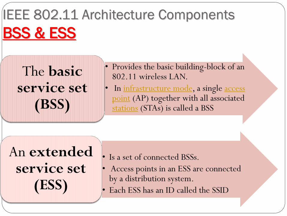
IEEE 802.11 Architecture Components
BSS & ESS
• Provides the basic building-block of an 802.11 wireless LAN.
• In infrastructure mode, a single access point (AP) together with all associated stations (STAs) is called a BSS
The basic service set
(BSS)
• Is a set of connected BSSs.
• Access points in an ESS are connected by a distribution system.
• Each ESS has an ID called the SSID
An extended service set
(ESS)
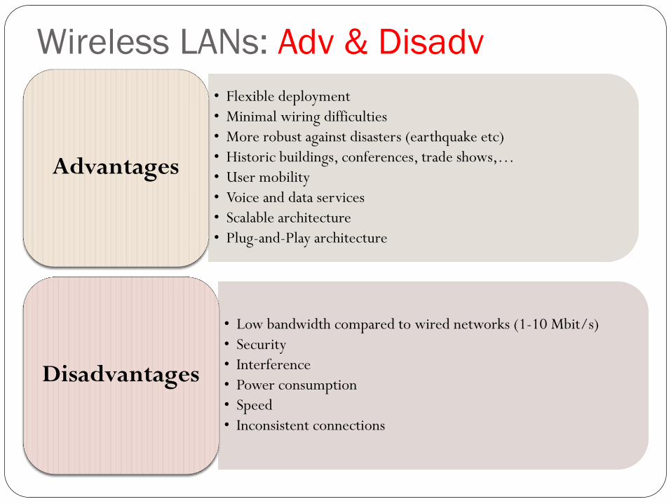
Wireless LANs: Adv & Disadv
• Flexible deployment
• Minimal wiring difficulties
• More robust against disasters (earthquake etc)
• Historic buildings, conferences, trade shows,…
• User mobility
• Voice and data services
• Scalable architecture
• Plug-and-Play architecture
Advantages
• Low bandwidth compared to wired networks (1-10 Mbit/s)
• Security
• Interference
• Power consumption
• Speed
• Inconsistent connections
Disadvantages
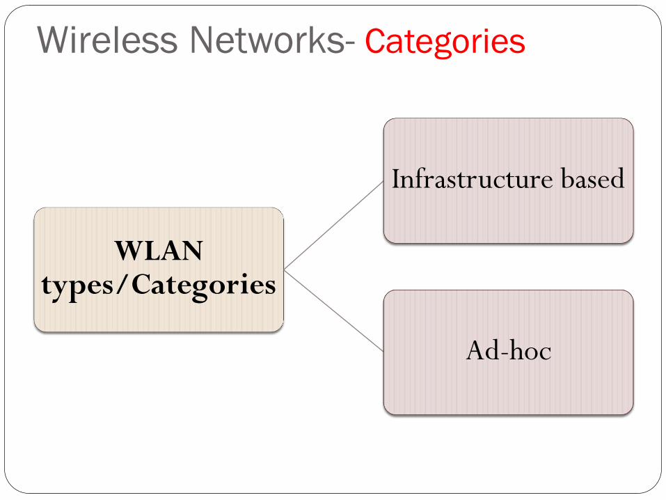
Wireless Networks- Categories
WLAN types/Categories
Infrastructure based
Ad-hoc
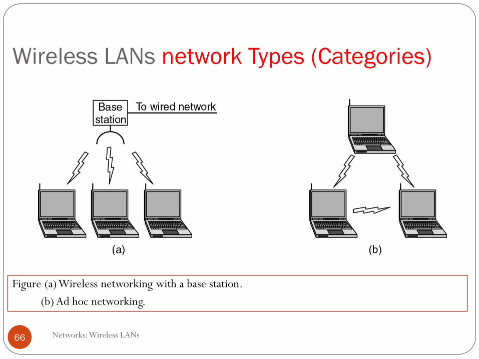
Wireless LANs network Types (Categories)
Networks: Wireless LANs 66
Figure (a) Wireless networking with a base station.
(b) Ad hoc networking.
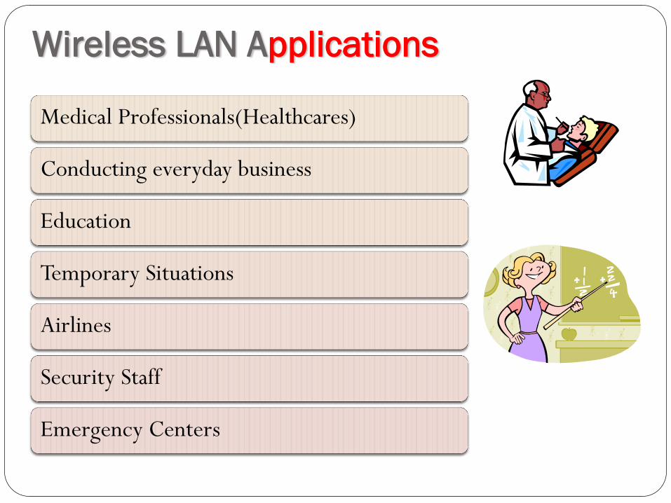
Wireless LAN Applications
Medical Professionals(Healthcares)
Conducting everyday business
Education
Temporary Situations
Airlines
Security Staff
Emergency Centers
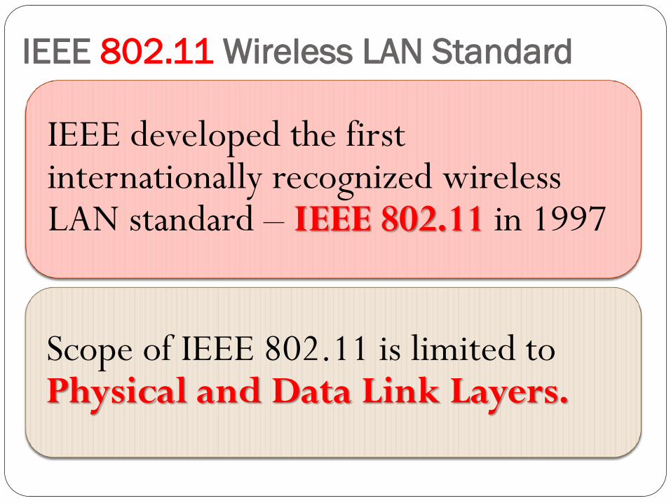
IEEE 802.11 Wireless LAN Standard
IEEE developed the first internationally recognized wireless LAN standard – IEEE 802.11 in 1997
Scope of IEEE 802.11 is limited to Physical and Data Link Layers.
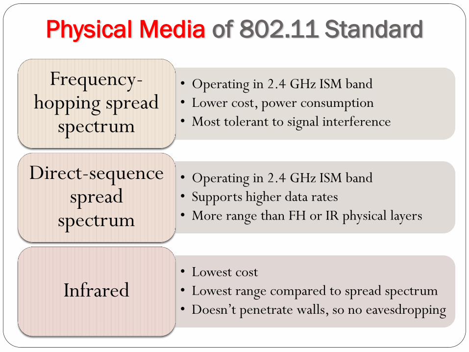
Physical Media of 802.11 Standard
• Operating in 2.4 GHz ISM band
• Lower cost, power consumption
• Most tolerant to signal interference
Frequency-hopping spread
spectrum
• Operating in 2.4 GHz ISM band
• Supports higher data rates
• More range than FH or IR physical layers
Direct-sequence spread
spectrum
• Lowest cost
• Lowest range compared to spread spectrum
• Doesn’t penetrate walls, so no eavesdropping Infrared
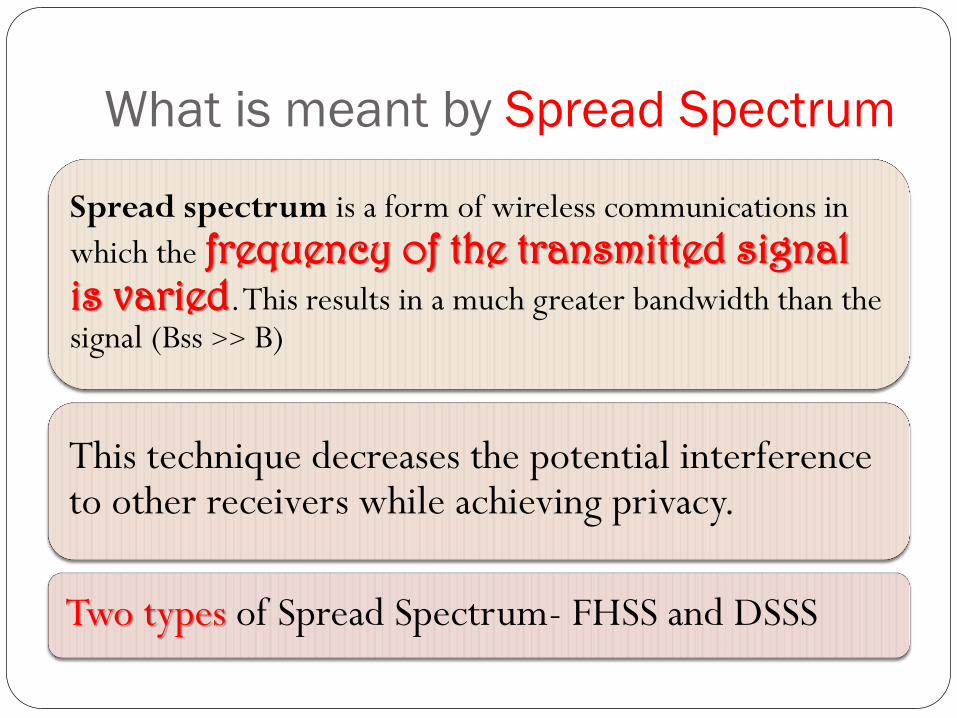
What is meant by Spread Spectrum
Spread spectrum is a form of wireless communications in
which the frequency of the transmitted signal is varied. This results in a much greater bandwidth than the signal (Bss >> B)
This technique decreases the potential interference to other receivers while achieving privacy.
Two types of Spread Spectrum- FHSS and DSSS
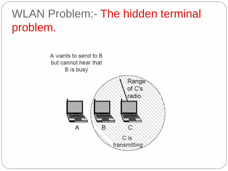
WLAN Problem:- The hidden terminal
problem.
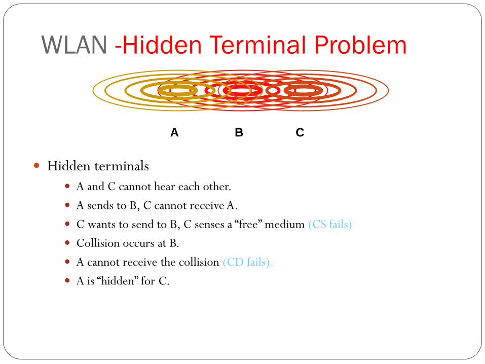
WLAN -Hidden Terminal Problem
Hidden terminals
A and C cannot hear each other.
A sends to B, C cannot receive A.
C wants to send to B, C senses a “free” medium (CS fails)
Collision occurs at B.
A cannot receive the collision (CD fails).
A is “hidden” for C.
B A C
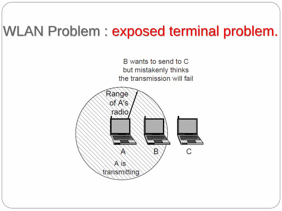
WLAN Problem : exposed terminal problem.
WLAN Problem- Solution
MAC Layer

IEEE 802.11 Medium Access Control
MAC layer covers three functional areas:
Reliable data
delivery
Access control
Security
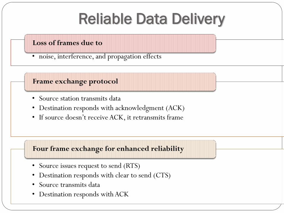
Reliable Data Delivery
• noise, interference, and propagation effects
Loss of frames due to
• Source station transmits data
• Destination responds with acknowledgment (ACK)
• If source doesn’t receive ACK, it retransmits frame
Frame exchange protocol
• Source issues request to send (RTS)
• Destination responds with clear to send (CTS)
• Source transmits data
• Destination responds with ACK
Four frame exchange for enhanced reliability
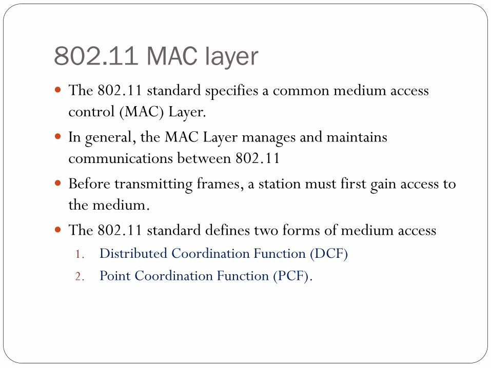
802.11 MAC layer The 802.11 standard specifies a common medium access
control (MAC) Layer.
In general, the MAC Layer manages and maintains
communications between 802.11
Before transmitting frames, a station must first gain access to
the medium.
The 802.11 standard defines two forms of medium access
1. Distributed Coordination Function (DCF)
2. Point Coordination Function (PCF).
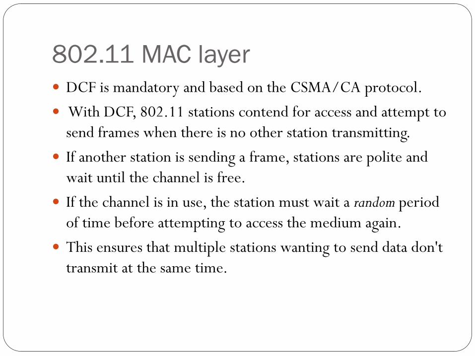
802.11 MAC layer DCF is mandatory and based on the CSMA/CA protocol.
With DCF, 802.11 stations contend for access and attempt to
send frames when there is no other station transmitting.
If another station is sending a frame, stations are polite and
wait until the channel is free.
If the channel is in use, the station must wait a random period
of time before attempting to access the medium again.
This ensures that multiple stations wanting to send data don't
transmit at the same time.
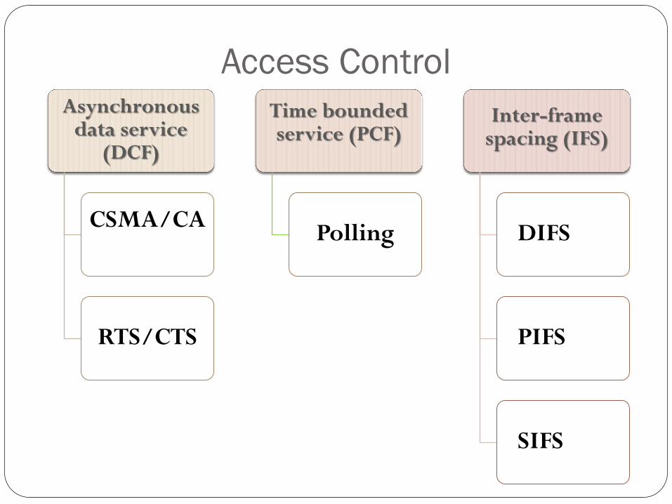
Access Control Asynchronous
data service (DCF)
CSMA/CA
RTS/CTS
Time bounded service (PCF)
Polling
Inter-frame spacing (IFS)
DIFS
PIFS
SIFS
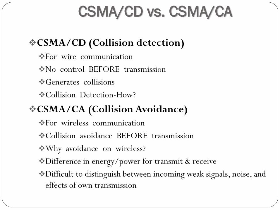
CSMA/CD vs. CSMA/CA
CSMA/CD (Collision detection)
For wire communication
No control BEFORE transmission
Generates collisions
Collision Detection-How?
CSMA/CA (Collision Avoidance)
For wireless communication
Collision avoidance BEFORE transmission
Why avoidance on wireless?
Difference in energy/power for transmit & receive
Difficult to distinguish between incoming weak signals, noise, and
effects of own transmission
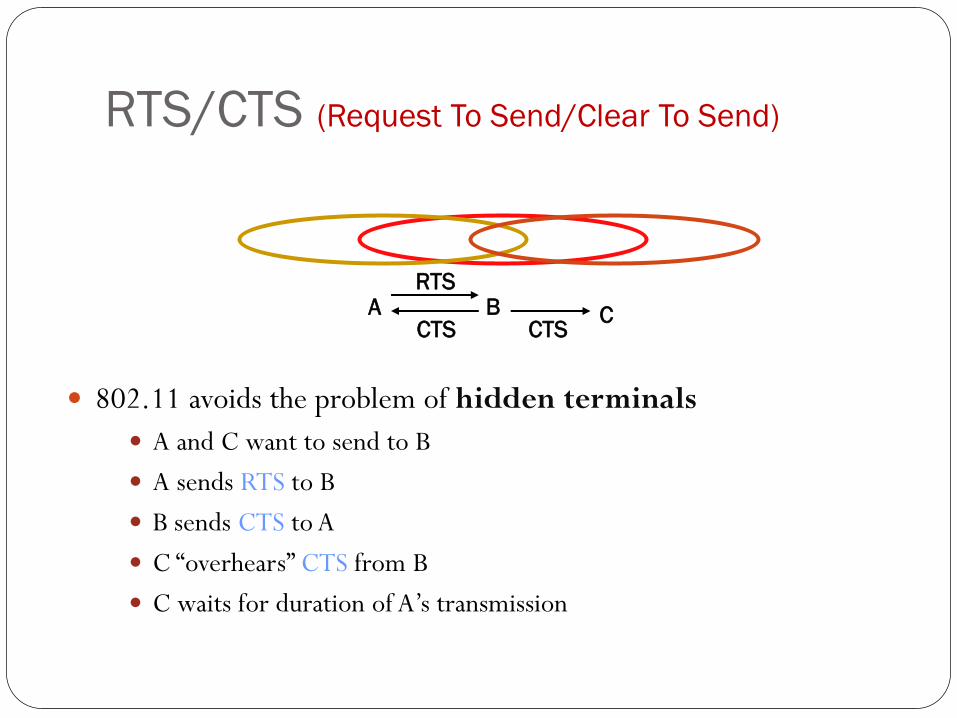
RTS/CTS (Request To Send/Clear To Send)
802.11 avoids the problem of hidden terminals
A and C want to send to B
A sends RTS to B
B sends CTS to A
C “overhears” CTS from B
C waits for duration of A’s transmission
A B C
RTS
CTS CTS

The 802.11 MAC Sublayer Protocol (
The use of virtual channel sensing using CSMA/CA.
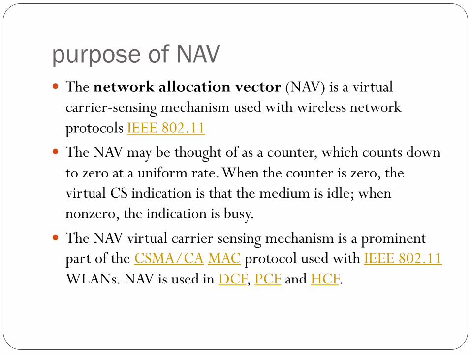
purpose of NAV The network allocation vector (NAV) is a virtual
carrier-sensing mechanism used with wireless network
protocols IEEE 802.11
The NAV may be thought of as a counter, which counts down
to zero at a uniform rate. When the counter is zero, the
virtual CS indication is that the medium is idle; when
nonzero, the indication is busy.
The NAV virtual carrier sensing mechanism is a prominent
part of the CSMA/CA MAC protocol used with IEEE 802.11
WLANs. NAV is used in DCF, PCF and HCF.
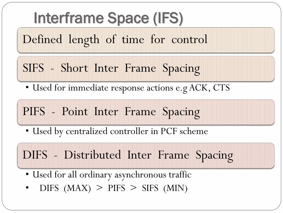
Interframe Space (IFS)
Defined length of time for control
SIFS - Short Inter Frame Spacing
• Used for immediate response actions e.g ACK, CTS
PIFS - Point Inter Frame Spacing
• Used by centralized controller in PCF scheme
DIFS - Distributed Inter Frame Spacing
• Used for all ordinary asynchronous traffic
• DIFS (MAX) > PIFS > SIFS (MIN)
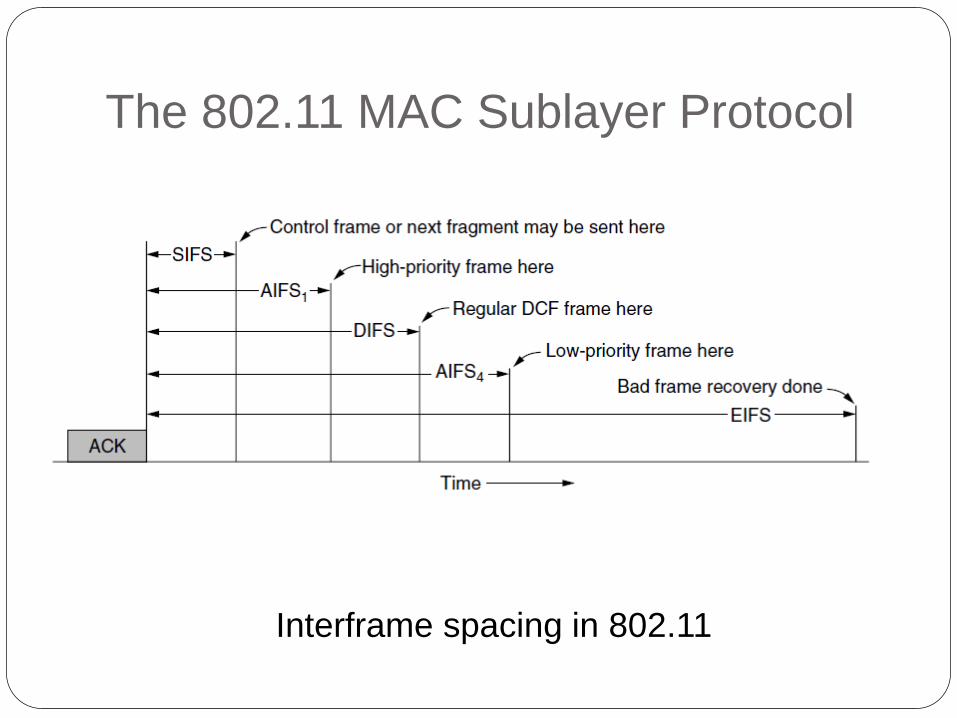
The 802.11 MAC Sublayer Protocol
Interframe spacing in 802.11
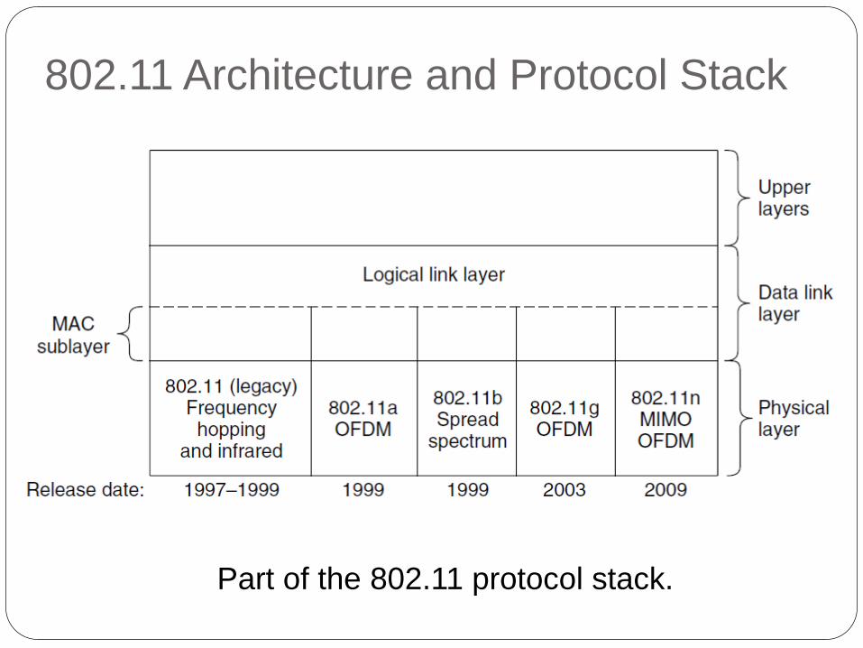
802.11 Architecture and Protocol Stack
Part of the 802.11 protocol stack.
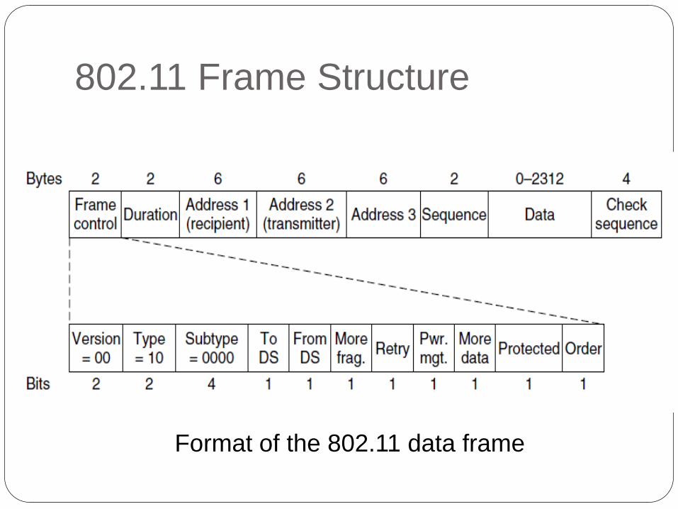
802.11 Frame Structure
Format of the 802.11 data frame
Frame Control field Protocol Version:
zero for 802.11 standard
Type= frame type:
data, management, control
Subtype = frame sub-type:
ToDS:
When bit is set indicate that destination frame is for DS
FromDS:
When bit is set indicate frame coming from DS
Frame Control field Retry:
Set in case of retransmission frame
More fragments: Set when frame is followed by other fragment
Power Management
bit set when station go Power Save mode (PS)
More Data: When set means that AP have more buffered data for a station in Power Save mode
Frame Control field
WEP:
When set indicate that in the Frame Body field there are datas
need to processed by WEP algorithm.
Order:
When set indicate restrictions for transmission
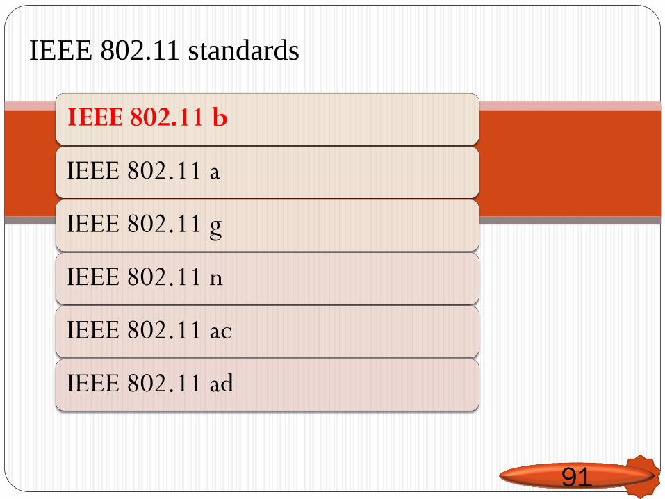
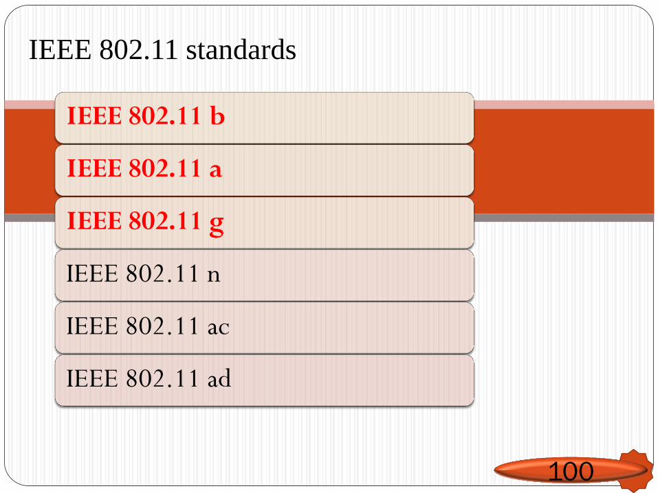
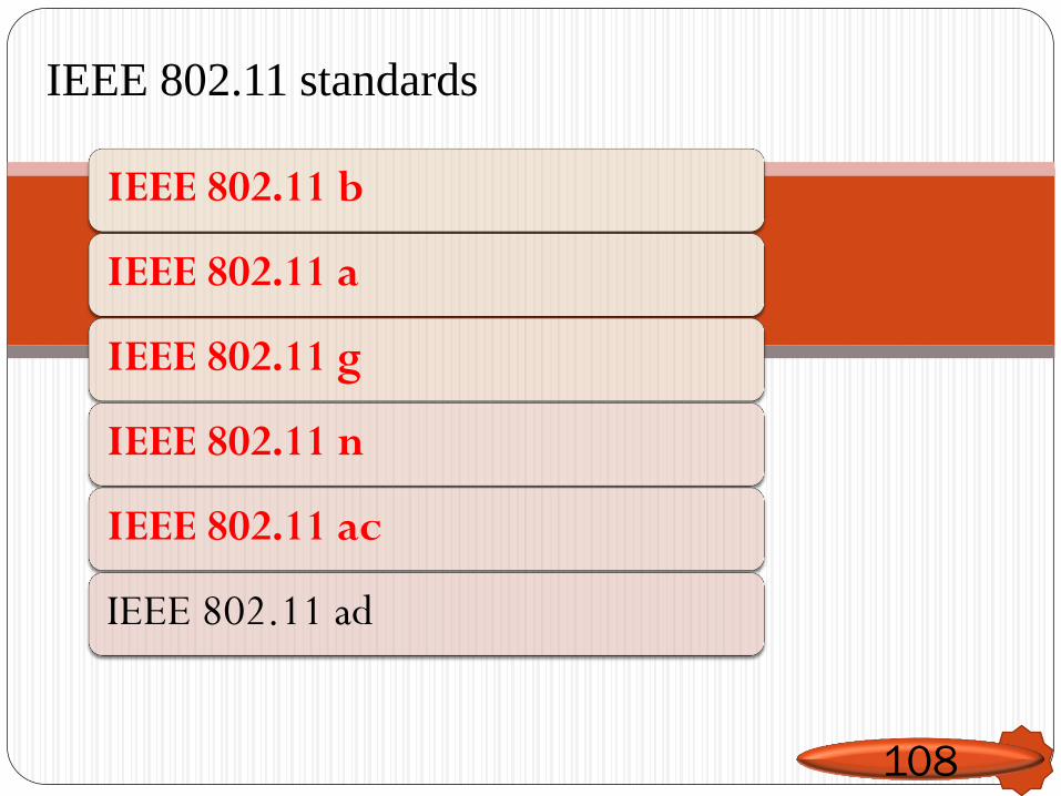
IEEE 802.11 standards
IEEE 802.11 b
IEEE 802.11 a
IEEE 802.11 g
IEEE 802.11 n
IEEE 802.11 ac
IEEE 802.11 ad
91
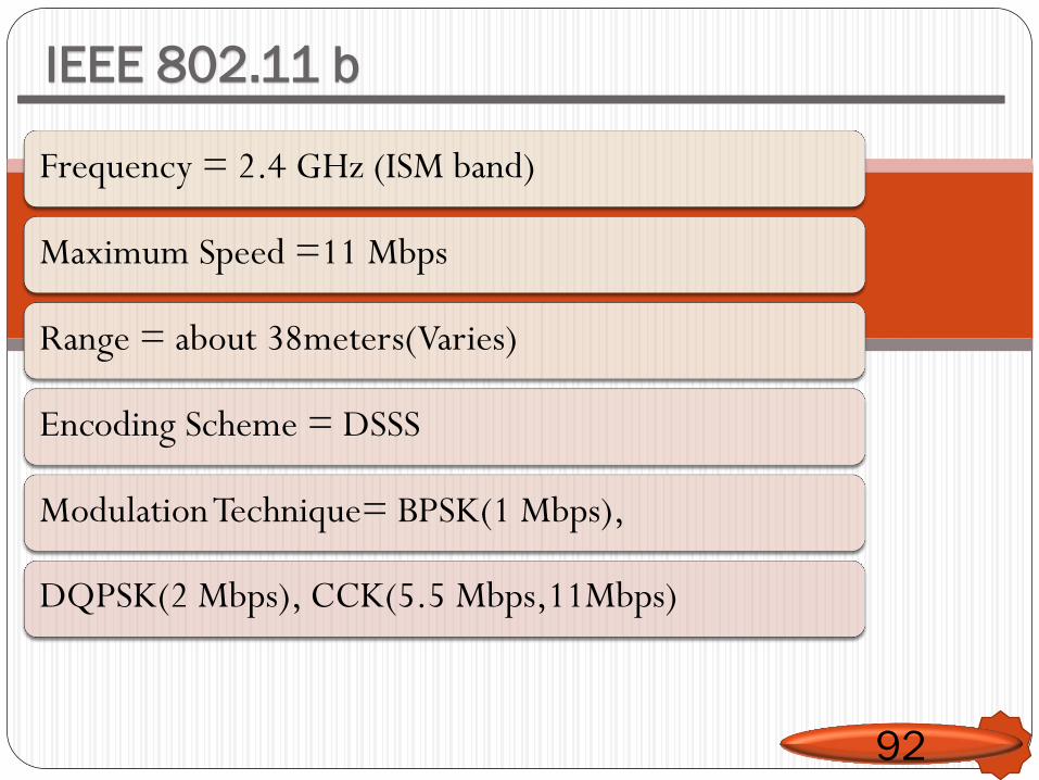
IEEE 802.11 b
92
Frequency = 2.4 GHz (ISM band)
Maximum Speed =11 Mbps
Range = about 38meters(Varies)
Encoding Scheme = DSSS
Modulation Technique= BPSK(1 Mbps),
DQPSK(2 Mbps), CCK(5.5 Mbps,11Mbps)
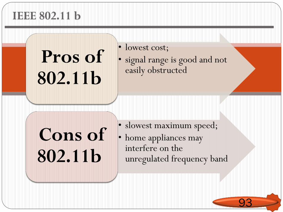
IEEE 802.11 b
93
• lowest cost;
• signal range is good and not easily obstructed
Pros of 802.11b
• slowest maximum speed;
• home appliances may interfere on the unregulated frequency band
Cons of 802.11b
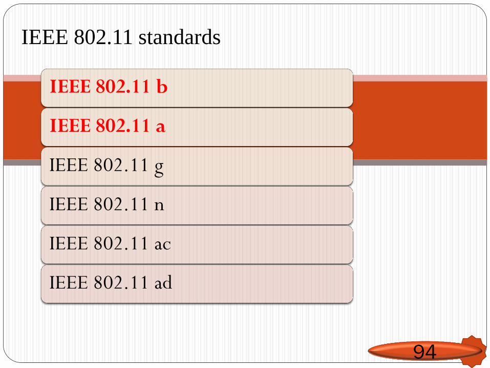
IEEE 802.11 standards
IEEE 802.11 b
IEEE 802.11 a
IEEE 802.11 g
IEEE 802.11 n
IEEE 802.11 ac
IEEE 802.11 ad
94
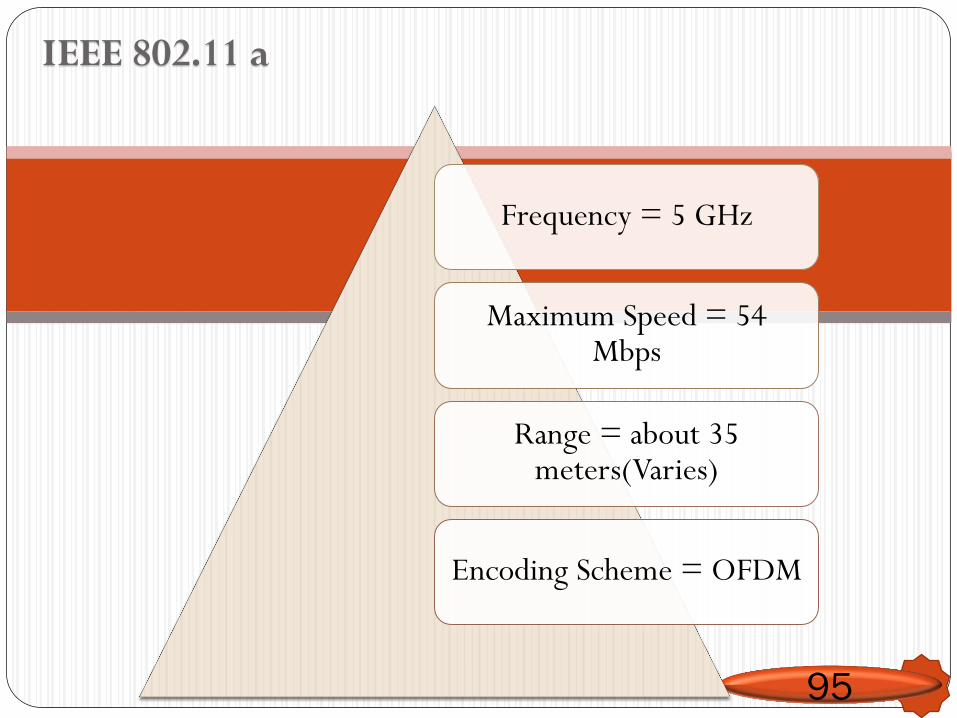
IEEE 802.11 a
95
Frequency = 5 GHz
Maximum Speed = 54 Mbps
Range = about 35 meters(Varies)
Encoding Scheme = OFDM
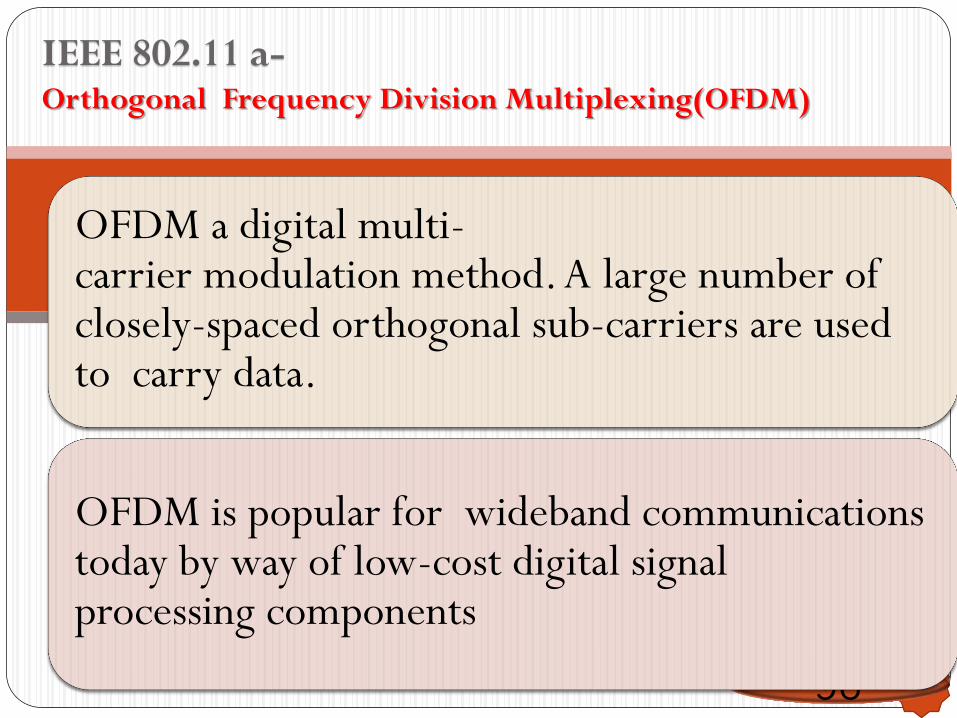
IEEE 802.11 a- Orthogonal Frequency Division Multiplexing(OFDM)
96
OFDM a digital multi-carrier modulation method. A large number of closely-spaced orthogonal sub-carriers are used to carry data.
OFDM is popular for wideband communications today by way of low-cost digital signal processing components
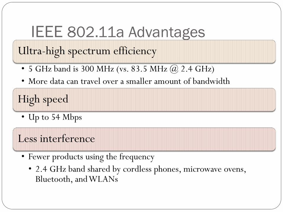
IEEE 802.11a Advantages Ultra-high spectrum efficiency
• 5 GHz band is 300 MHz (vs. 83.5 MHz @ 2.4 GHz)
• More data can travel over a smaller amount of bandwidth
High speed
• Up to 54 Mbps
Less interference
• Fewer products using the frequency
• 2.4 GHz band shared by cordless phones, microwave ovens, Bluetooth, and WLANs
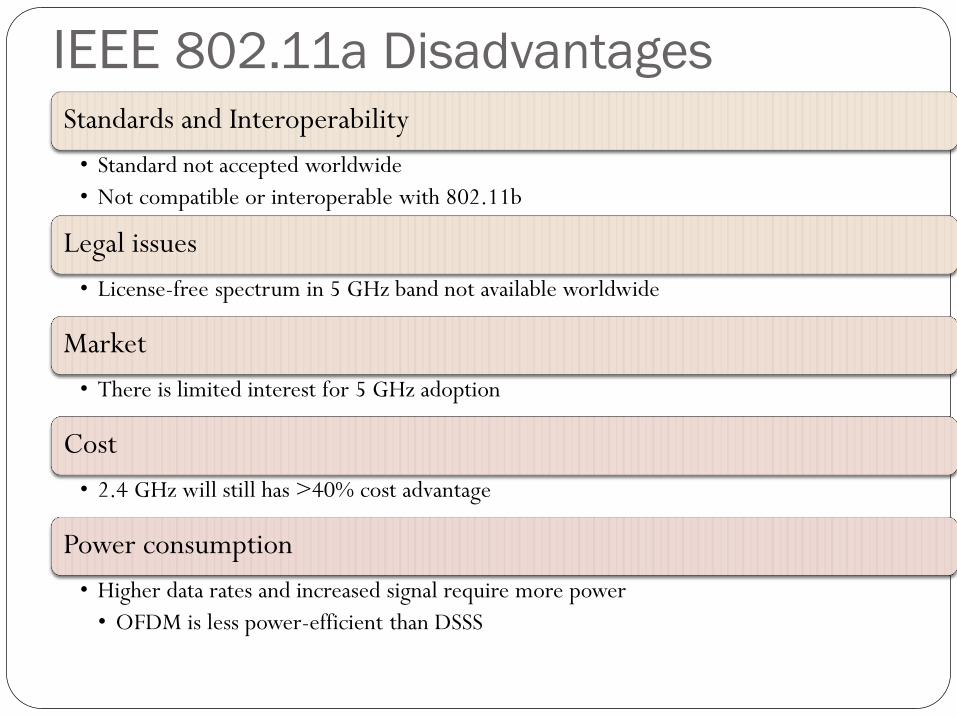
IEEE 802.11a Disadvantages
Standards and Interoperability
• Standard not accepted worldwide
• Not compatible or interoperable with 802.11b
Legal issues
• License-free spectrum in 5 GHz band not available worldwide
Market
• There is limited interest for 5 GHz adoption
Cost
• 2.4 GHz will still has >40% cost advantage
Power consumption
• Higher data rates and increased signal require more power
• OFDM is less power-efficient than DSSS
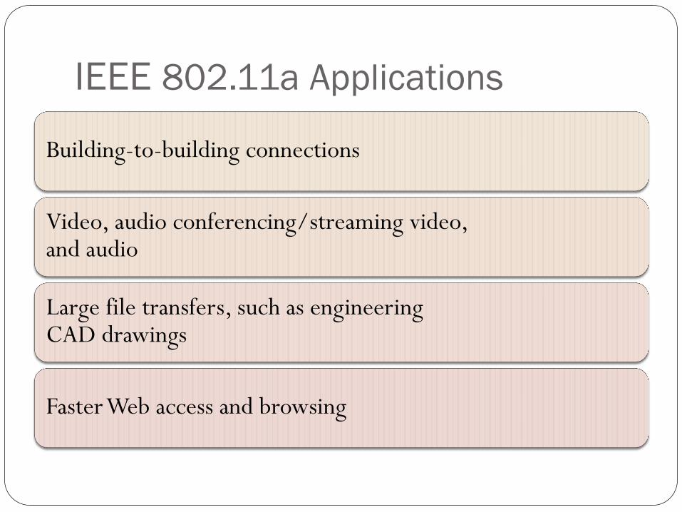
IEEE 802.11a Applications
Building-to-building connections
Video, audio conferencing/streaming video, and audio
Large file transfers, such as engineering CAD drawings
Faster Web access and browsing
IEEE 802.11 standards
IEEE 802.11 b
IEEE 802.11 a
IEEE 802.11 g
IEEE 802.11 n
IEEE 802.11 ac
IEEE 802.11 ad
100
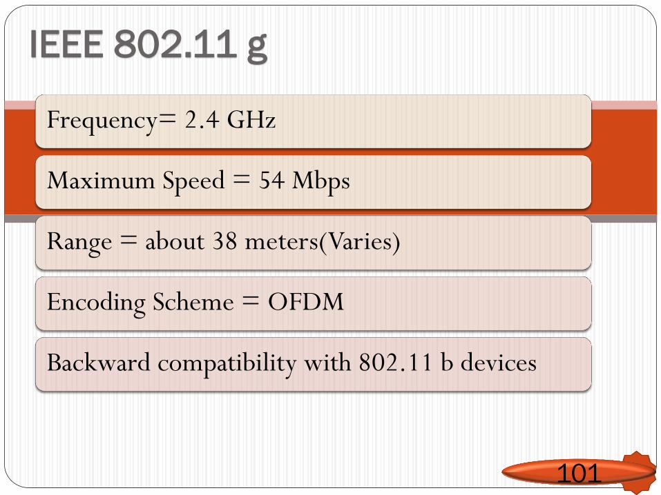
IEEE 802.11 g
101
Frequency= 2.4 GHz
Maximum Speed = 54 Mbps
Range = about 38 meters(Varies)
Encoding Scheme = OFDM
Backward compatibility with 802.11 b devices
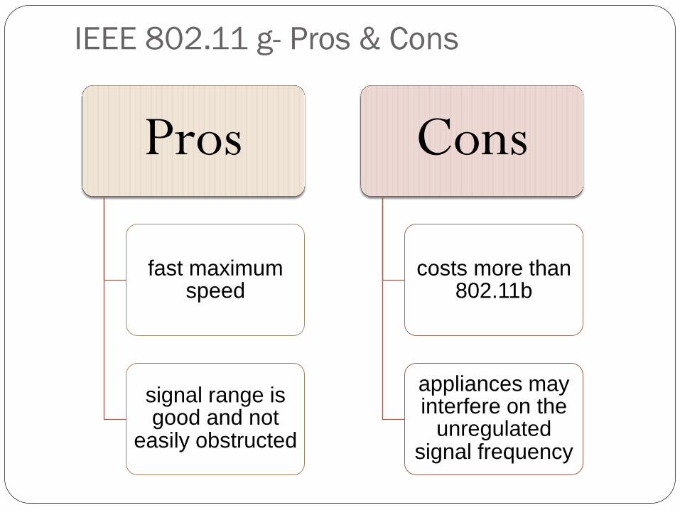
IEEE 802.11 g- Pros & Cons
Pros
fast maximum speed
signal range is good and not
easily obstructed
Cons
costs more than 802.11b
appliances may interfere on the
unregulated signal frequency
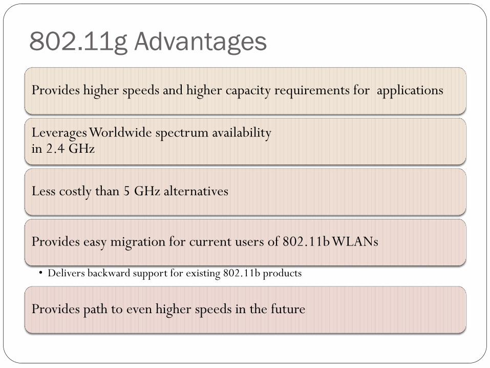
802.11g Advantages
Provides higher speeds and higher capacity requirements for applications
Leverages Worldwide spectrum availability in 2.4 GHz
Less costly than 5 GHz alternatives
Provides easy migration for current users of 802.11b WLANs
• Delivers backward support for existing 802.11b products
Provides path to even higher speeds in the future
IEEE 802.11 standards
IEEE 802.11 b
IEEE 802.11 a
IEEE 802.11 g
IEEE 802.11 n
IEEE 802.11 ac
IEEE 802.11 ad
104
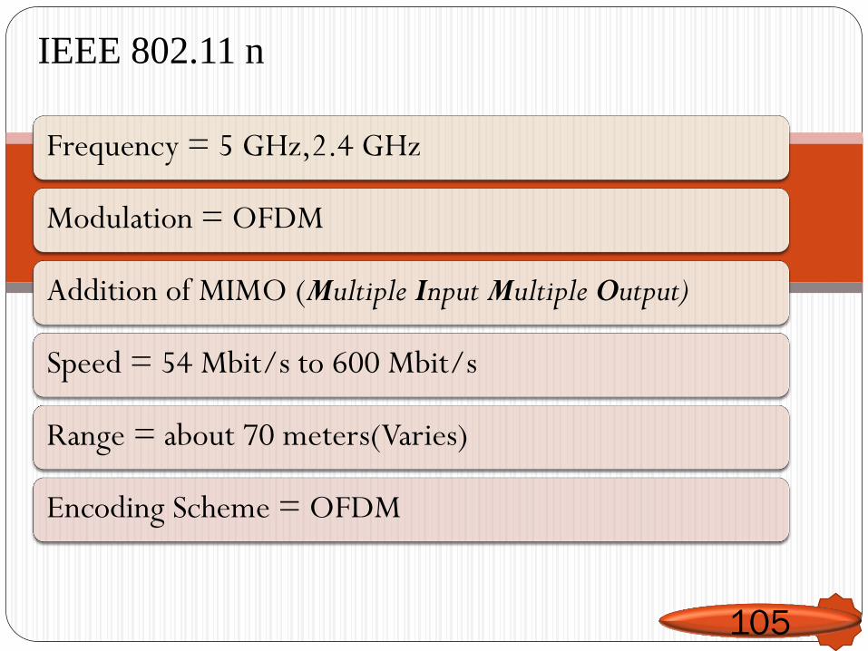
IEEE 802.11 n
105
Frequency = 5 GHz,2.4 GHz
Modulation = OFDM
Addition of MIMO (Multiple Input Multiple Output)
Speed = 54 Mbit/s to 600 Mbit/s
Range = about 70 meters(Varies)
Encoding Scheme = OFDM
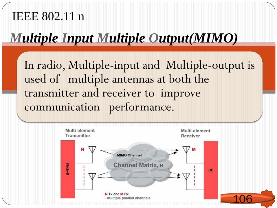
IEEE 802.11 n
Multiple Input Multiple Output(MIMO)
106
In radio, Multiple-input and Multiple-output is used of multiple antennas at both the transmitter and receiver to improve communication performance.
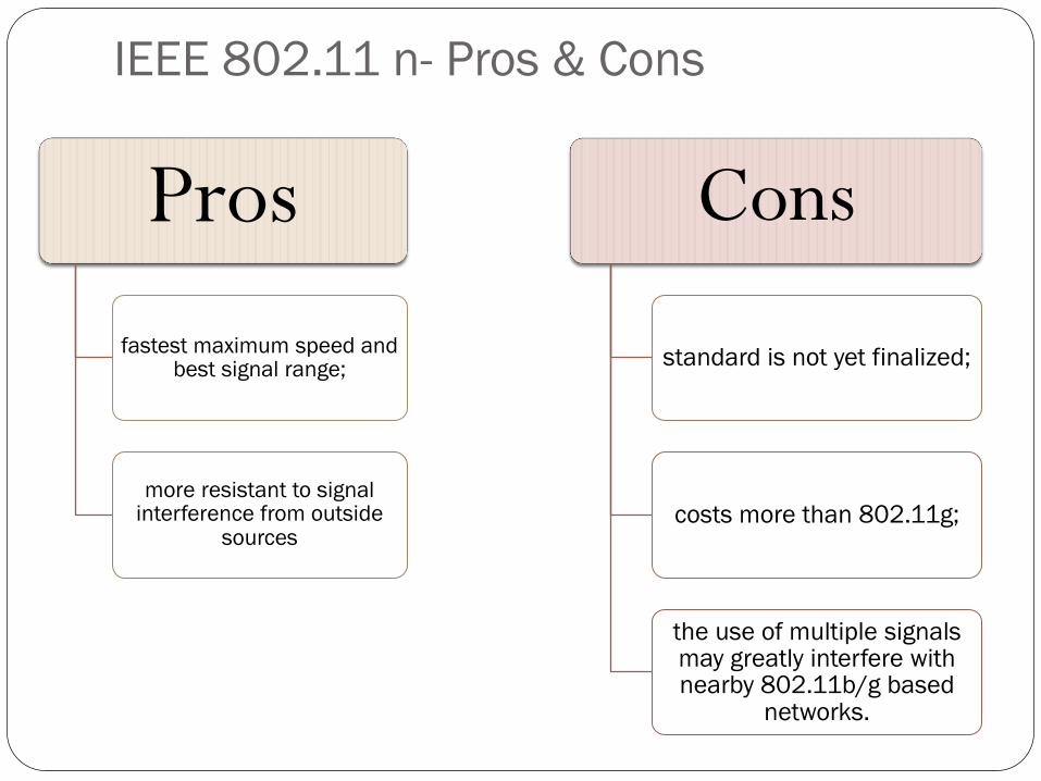
IEEE 802.11 n- Pros & Cons
Pros
fastest maximum speed and best signal range;
more resistant to signal interference from outside
sources
Cons
standard is not yet finalized;
costs more than 802.11g;
the use of multiple signals may greatly interfere with nearby 802.11b/g based
networks.
IEEE 802.11 standards
IEEE 802.11 b
IEEE 802.11 a
IEEE 802.11 g
IEEE 802.11 n
IEEE 802.11 ac
IEEE 802.11 ad
108
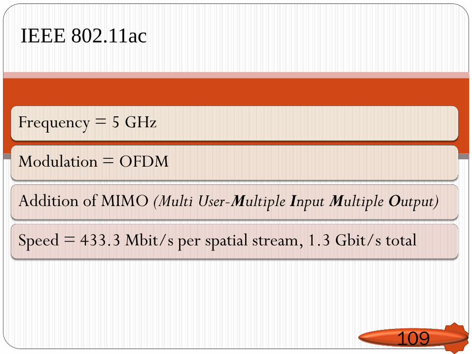
IEEE 802.11ac
109
Frequency = 5 GHz
Modulation = OFDM
Addition of MIMO (Multi User-Multiple Input Multiple Output)
Speed = 433.3 Mbit/s per spatial stream, 1.3 Gbit/s total
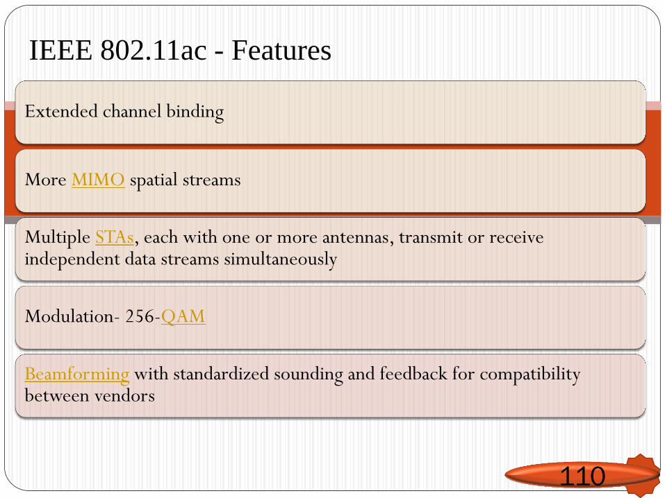
IEEE 802.11ac - Features
110
Extended channel binding
More MIMO spatial streams
Multiple STAs, each with one or more antennas, transmit or receive independent data streams simultaneously
Modulation- 256-QAM
Beamforming with standardized sounding and feedback for compatibility between vendors
IEEE 802.11ac Applications
111
Highly interactive video gaming, video conferencing,
High definition video streaming and
Many more applications that need data at rates that push the boundaries of exiting Wi-Fi systems.

IEEE 802.11 standards
IEEE 802.11 b
IEEE 802.11 a
IEEE 802.11 g
IEEE 802.11 n
IEEE 802.11 ac
IEEE 802.11 ad
112
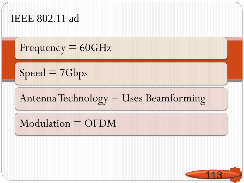
IEEE 802.11 ad
113
Frequency = 60GHz
Speed = 7Gbps
Antenna Technology = Uses Beamforming
Modulation = OFDM
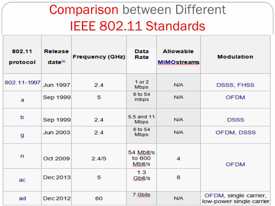
Comparison between Different
IEEE 802.11 Standards
Outline
Channel allocation: Static and Dynamic,
Multiple Access Protocols: Pure and Slotted ALOHA, CSMA, CSMA/CD, CSMA/CA, WDMA
IEEE 802.3 Standards and Frame Formats,
Binary Exponential Back -off algorithm,
Fast Ethernet, Gigabit Ethernet,
IEEE 802.11a/b/g/n
IEEE 802.15
IEEE 802.16 Standards, Frame formats,
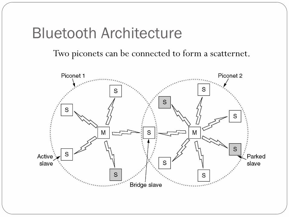
Bluetooth Architecture
Two piconets can be connected to form a scatternet.
Bluetooth Architecture(2)
Piconet consist of a master node and up to seven active slaves
within a distance of 10 meters
In addition to seven active slave nodes , there can be up to 255
parked nodes in the net
All communication is between master/slave. slave-/slave
communication is not possible
Multiple piconets can exist in the same room and can even be
connected via a bridge node.
Interconnected collection of piconets is called as scatternet.
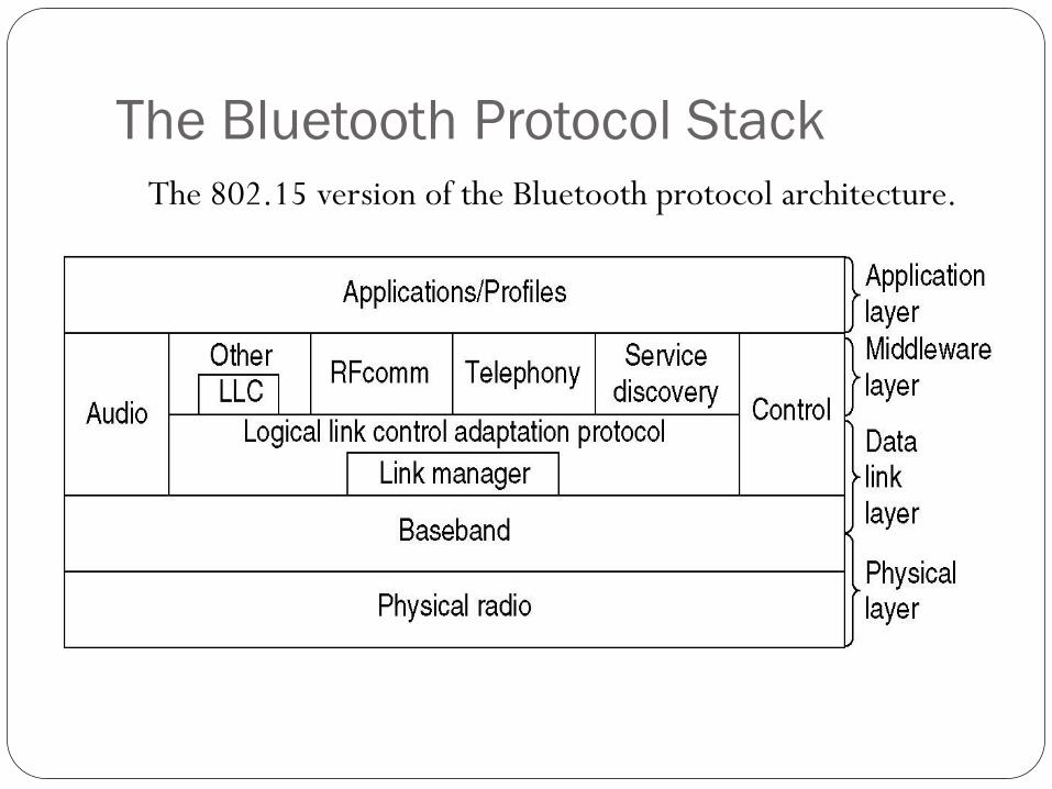
The Bluetooth Protocol Stack
The 802.15 version of the Bluetooth protocol architecture.
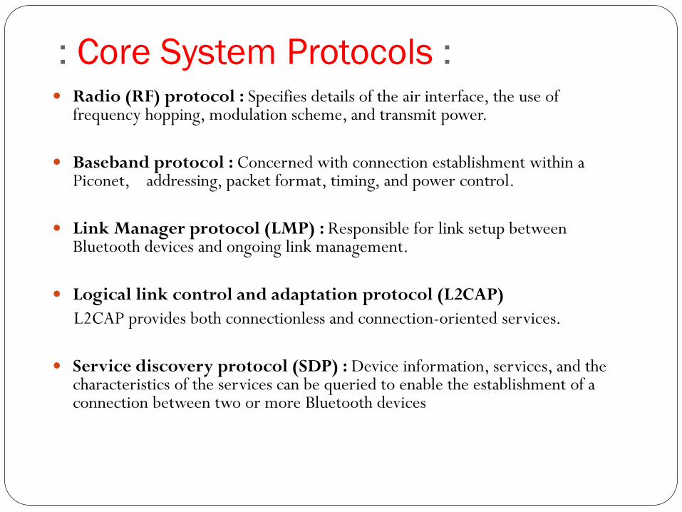
: Core System Protocols : Radio (RF) protocol : Specifies details of the air interface, the use of
frequency hopping, modulation scheme, and transmit power.
Baseband protocol : Concerned with connection establishment within a Piconet, addressing, packet format, timing, and power control.
Link Manager protocol (LMP) : Responsible for link setup between Bluetooth devices and ongoing link management.
Logical link control and adaptation protocol (L2CAP)
L2CAP provides both connectionless and connection-oriented services.
Service discovery protocol (SDP) : Device information, services, and the characteristics of the services can be queried to enable the establishment of a connection between two or more Bluetooth devices
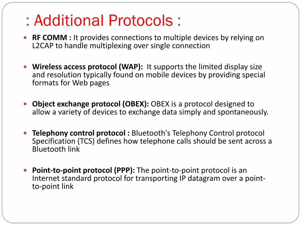
: Additional Protocols : RF COMM : It provides connections to multiple devices by relying on
L2CAP to handle multiplexing over single connection
Wireless access protocol (WAP): It supports the limited display size and resolution typically found on mobile devices by providing special formats for Web pages
Object exchange protocol (OBEX): OBEX is a protocol designed to allow a variety of devices to exchange data simply and spontaneously.
Telephony control protocol : Bluetooth's Telephony Control protocol Specification (TCS) defines how telephone calls should be sent across a Bluetooth link
Point-to-point protocol (PPP): The point-to-point protocol is an Internet standard protocol for transporting IP datagram over a point-to-point link
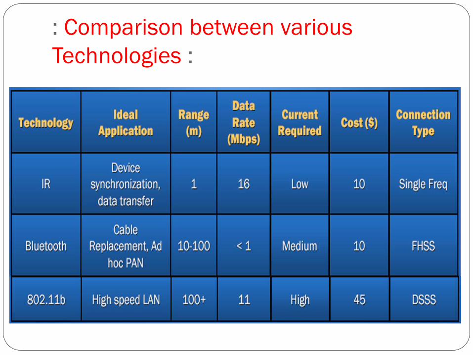
: Comparison between various
Technologies :
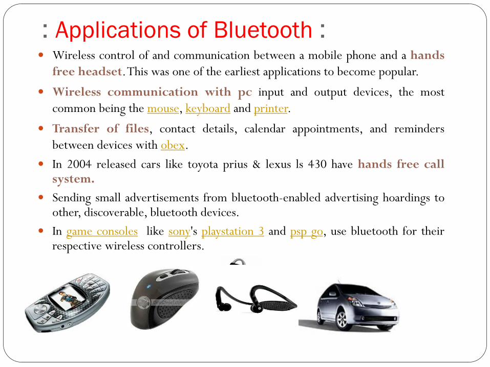
: Applications of Bluetooth : Wireless control of and communication between a mobile phone and a hands
free headset. This was one of the earliest applications to become popular.
Wireless communication with pc input and output devices, the most
common being the mouse, keyboard and printer.
Transfer of files, contact details, calendar appointments, and reminders
between devices with obex.
In 2004 released cars like toyota prius & lexus ls 430 have hands free call system.
Sending small advertisements from bluetooth-enabled advertising hoardings to other, discoverable, bluetooth devices.
In game consoles like sony's playstation 3 and psp go, use bluetooth for their respective wireless controllers.
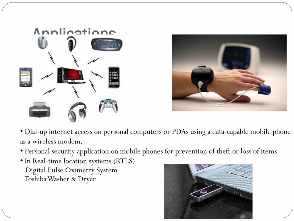
Applications
• Dial-up internet access on personal computers or PDAs using a data-capable mobile phone
as a wireless modem.
• Personal security application on mobile phones for prevention of theft or loss of items.
• In Real-time location systems (RTLS). Digital Pulse Oximetry System Toshiba Washer & Dryer.
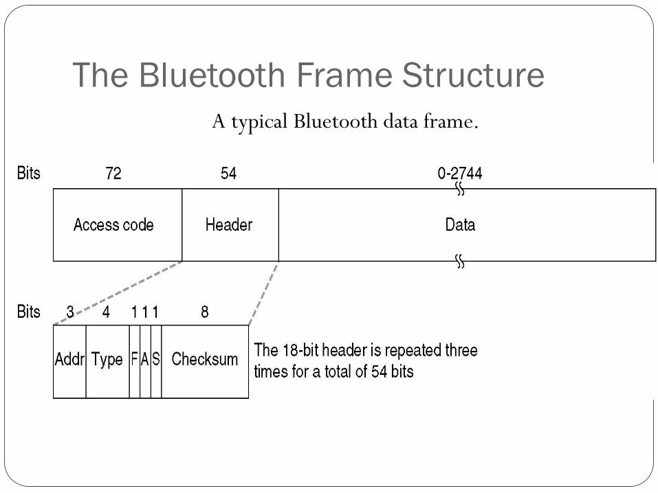
The Bluetooth Frame Structure
A typical Bluetooth data frame.
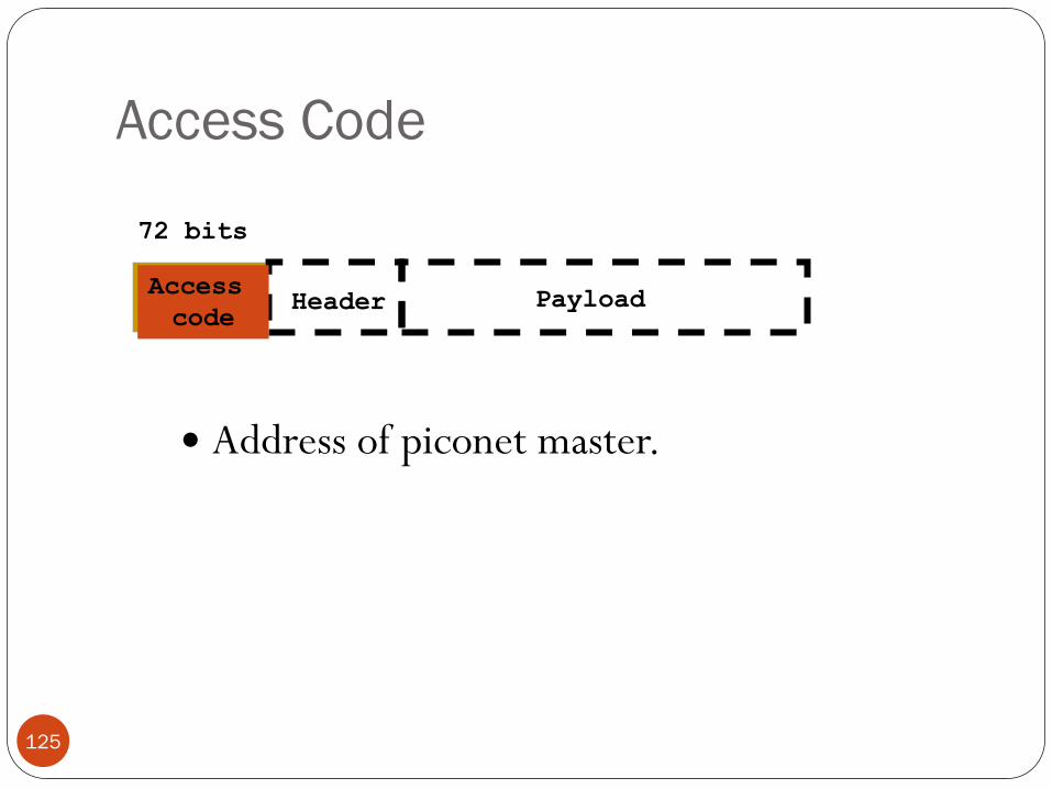
Access Code
125
Address of piconet master.
Access
code Header Payload
72 bits
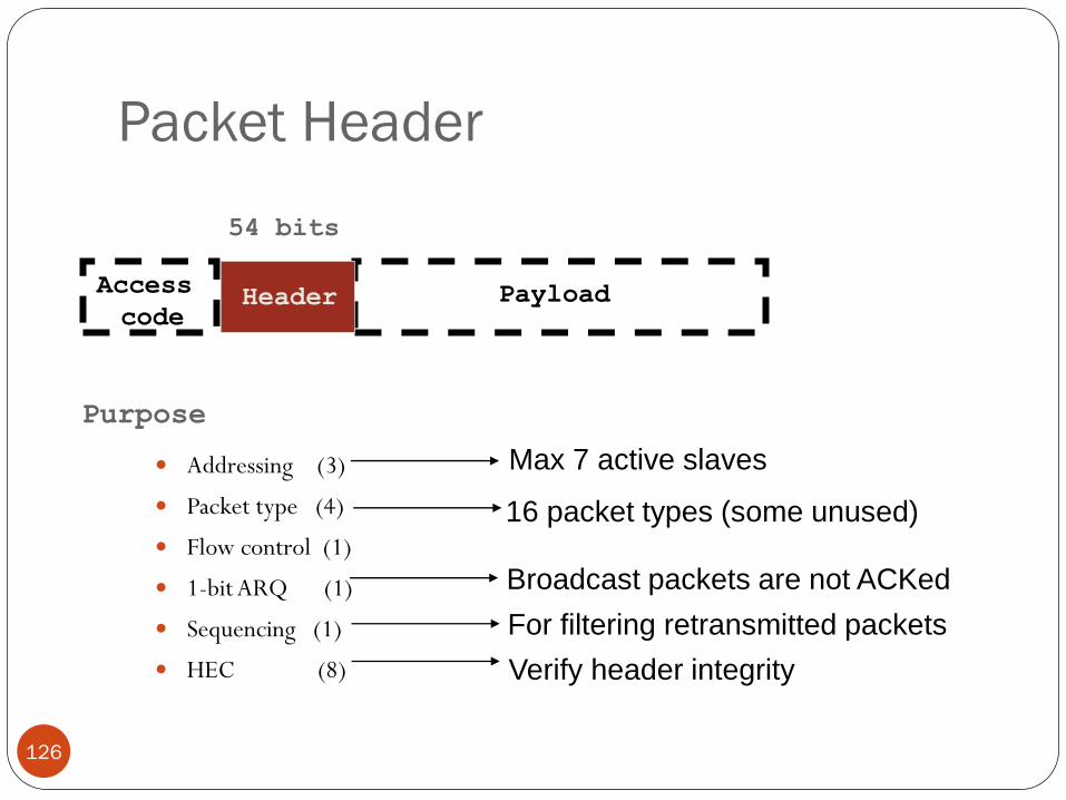
Packet Header
126
Addressing (3)
Packet type (4)
Flow control (1)
1-bit ARQ (1)
Sequencing (1)
HEC (8)
Access
code Header Payload
54 bits
Purpose
Broadcast packets are not ACKed
For filtering retransmitted packets
16 packet types (some unused)
Max 7 active slaves
Verify header integrity
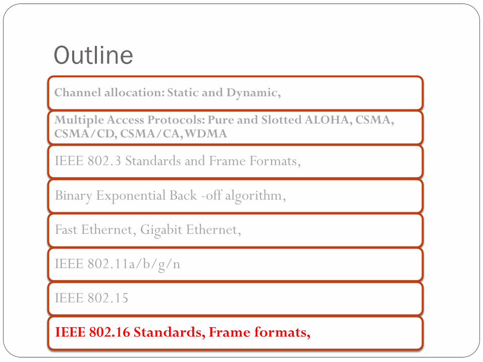
Outline
Channel allocation: Static and Dynamic,
Multiple Access Protocols: Pure and Slotted ALOHA, CSMA, CSMA/CD, CSMA/CA, WDMA
IEEE 802.3 Standards and Frame Formats,
Binary Exponential Back -off algorithm,
Fast Ethernet, Gigabit Ethernet,
IEEE 802.11a/b/g/n
IEEE 802.15
IEEE 802.16 Standards, Frame formats,
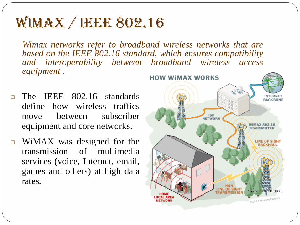
WIMAX / IEEE 802.16 Wimax networks refer to broadband wireless networks that are
based on the IEEE 802.16 standard, which ensures compatibility and interoperability between broadband wireless access equipment .
The IEEE 802.16 standards define how wireless traffics move between subscriber equipment and core networks.
WiMAX was designed for the transmission of multimedia services (voice, Internet, email, games and others) at high data rates.
Source: SHASHI JAKKU
WiMAX
WiMAX uses radio microwave technology to provide wireless
internet service to computers and other devices that are equipped
with WiMAX compatible chips for example PDA’s, cell phones etc.
It works more or less like cellular network technology.
The theoretical range of WiMAX is up to 30 miles and achieves
data rates up to 75 Mbps
WiMAX operates in similar manner as Wi-Fi but with two very
convincing differences as compared to Wi-Fi, these are :
o Data rate
o Data range
Features Use microwave for the wireless transfer of data.
Specifies a frequency band in the range between 2 GHz to 66 GHz.
For high speed wireless networking.
Basically, Wimax is a wireless internet service that is capable of
covering a wide geographical area by serving hundreds of users at a
very low cost.
Uses OFDM ,good for multipath environments.
It includes TDD and FDD duplexing support.
Flexible channel sizes (3.5 MHz,5 MHz,10MHz)
An easy and fast system to install.
Leading to low installation cost, when compared to fiber ,cable or
DSL deployments.
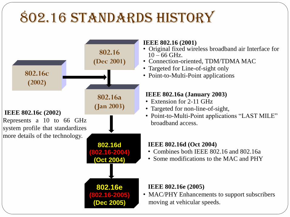
802.16 Standards History
802.16a (Jan 2003)
IEEE 802.16a (January 2003) • Extension for 2-11 GHz • Targeted for non-line-of-sight, • Point-to-Multi-Point applications “LAST MILE”
broadband access.
802.16 (Dec 2001)
IEEE 802.16 (2001) • Original fixed wireless broadband air Interface for 10 – 66 GHz. • Connection-oriented, TDM/TDMA MAC • Targeted for Line-of-sight only • Point-to-Multi-Point applications 802.16c
(2002)
IEEE 802.16c (2002)
Represents a 10 to 66 GHz
system profile that standardizes
more details of the technology.
802.16d (802.16-2004)
(Oct 2004)
IEEE 802.16d (Oct 2004) • Combines both IEEE 802.16 and 802.16a • Some modifications to the MAC and PHY
802.16e (802.16-2005)
(Dec 2005)
IEEE 802.16e (2005)
• MAC/PHY Enhancements to support subscribers
moving at vehicular speeds.
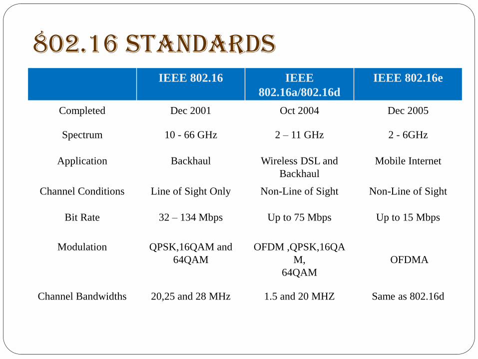
802.16 Standards IEEE 802.16 IEEE
802.16a/802.16d
IEEE 802.16e
Completed Dec 2001 Oct 2004 Dec 2005
Spectrum 10 - 66 GHz 2 – 11 GHz 2 - 6GHz
Application Backhaul Wireless DSL and
Backhaul
Mobile Internet
Channel Conditions Line of Sight Only Non-Line of Sight Non-Line of Sight
Bit Rate 32 – 134 Mbps Up to 75 Mbps Up to 15 Mbps
Modulation QPSK,16QAM and
64QAM
OFDM ,QPSK,16QA
M,
64QAM
OFDMA
Channel Bandwidths 20,25 and 28 MHz 1.5 and 20 MHZ Same as 802.16d
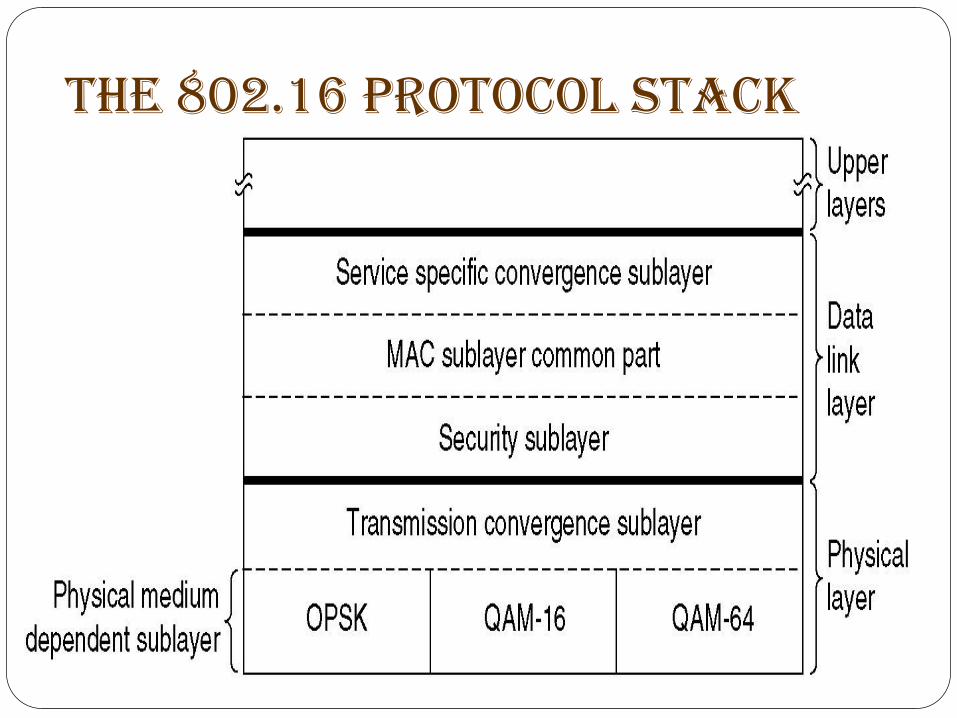
The 802.16 Protocol Stack
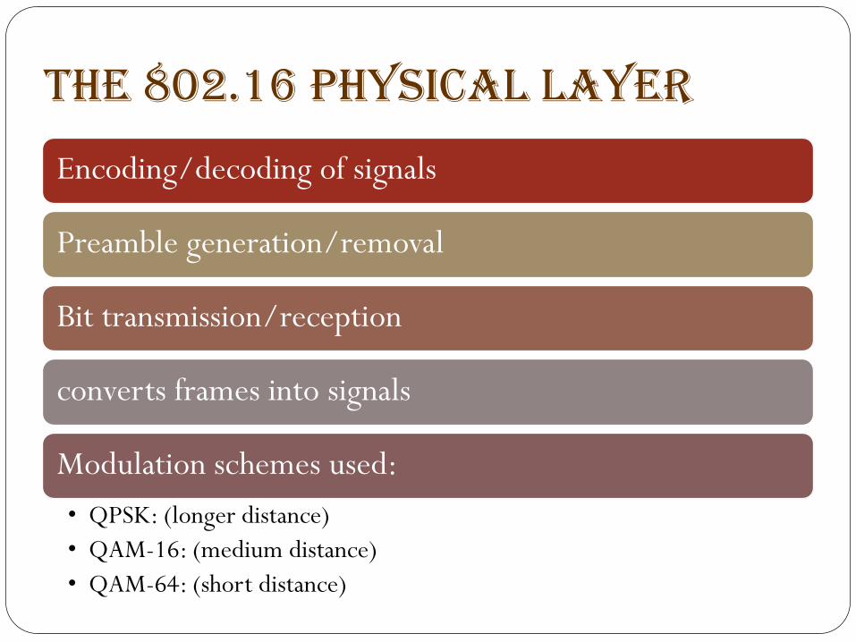
The 802.16 Physical Layer
Encoding/decoding of signals
Preamble generation/removal
Bit transmission/reception
converts frames into signals
Modulation schemes used:
• QPSK: (longer distance)
• QAM-16: (medium distance)
• QAM-64: (short distance)
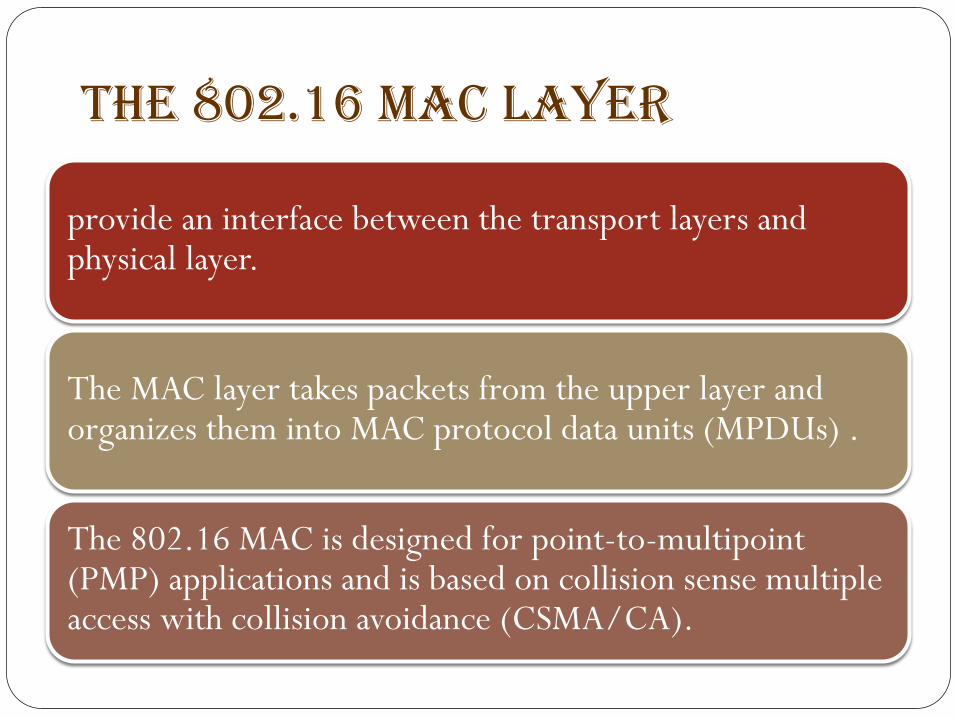
The 802.16 MAC Layer
provide an interface between the transport layers and physical layer.
The MAC layer takes packets from the upper layer and organizes them into MAC protocol data units (MPDUs) .
The 802.16 MAC is designed for point-to-multipoint (PMP) applications and is based on collision sense multiple access with collision avoidance (CSMA/CA).
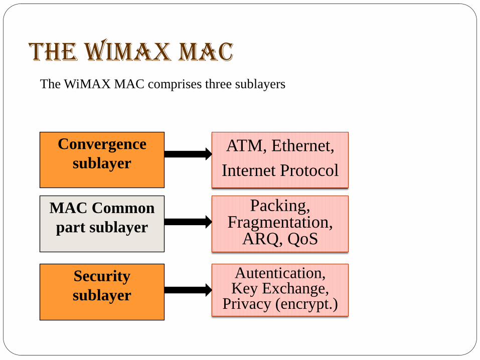
The WiMAX MAC
The WiMAX MAC comprises three sublayers
ATM, Ethernet,
Internet Protocol
Packing,
Fragmentation, ARQ, QoS
Autentication, Key Exchange,
Privacy (encrypt.)
Convergence
sublayer
MAC Common
part sublayer
Security
sublayer
MAC Convergence sublayer The service specific convergence sublayer (CS) provides any
transformation or mapping of external network data, received
through the CS service access point (SAP) into MAC SDUs received
by the MAC CPS through the MAC SAP.
Accepting higher layer protocol data units (PDUs) from the higher
layer
Performing classification of higher layer PDUs.
Associating them to the proper service flow identified by the
connection identifier (CID).
Delivering CS PDUs to the appropriate MAC SAP.
MAC Common part sublayer
Defines multiple-access mechanism
Bandwidth allocation
Connection establishment
Connection maintenance
Connection-oriented protocol
Assign connection ID to each service flow.
MAC Security sublayer
Deals with privacy and security.
The security sublayer provides subscribers with privacy or
confidentiality across the broadband wireless network.
It manages :
Authentication
Secure key exchange
Encryption
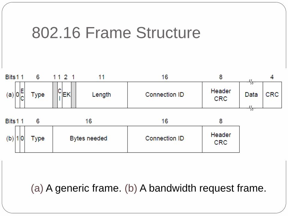
802.16 Frame Structure
(a) A generic frame. (b) A bandwidth request frame.

The 802.16 Frame Structure HT(Header type): For generic frame,HT=0
EC (Encryption control)
o 0 = Payload is not encrypted or payload is not included.
o 1 = Payload is encrypted.
Type : This field identifies the frame type ,whether packing and
fragmentation is present.
CI (CRC indicator)
o 1 = CRC is included .
o 0 = No CRC is included.
EKS (Encryption key sequence) : Which encryption key is used.
Length: Complete length of the frame including header.
Connection ID: Which connection this frame belongs to.
Header CRC: Header check sequence. An 8-bit field used to detect errors in
the header.Header check-sum using 100000111.
ESF(Extended subheader) ESF=0 ,absent:ESF=1.present
References
www.csie.cgu.edu.tw/~jhchen/course/CommSys/ch12.ppt
https://www.slideshare.net/kashyapshah11/bluetooth-10369755
my.fit.edu/~vkepuska/ece4561/Chapter4-MediumAccessControlSublayer.pptx
www.csie.cgu.edu.tw/~jhchen/course/WN/802.16Overview.ppt
http://webhome.csc.uvic.ca/~wkui/Courses/networks/Notes.html