UNIT II PART A (2 Marks) 1. What is the purpose of segment...
32
CS2252 MICROPROCESSORS & MICROCONTROLLERS Department of CSE MAHALAKSHMI ENGINEERING COLLEGE TIRUCHIRAPALLI-621213. UNIT II – 8086 Software Aspects PART A (2 Marks) 1. What is the purpose of segment registers in 8086? There are 4 segment registers present in 8086. They are 1. Code Segment (CS) register 2. Data Segment (DS) register 3. Stack Segment (SS) register 4. Extra Segment (ES) register The code segment register gives the segment address of the current code segment. The data segment register points out where the operands are stored in the memory. The stack segment registers points out the address of the current stack. The Extra segment registers points out where the large amount of data is stored in the memory. 2. What do you mean by pipelining in an 8086 processor?[NOV/DEC 2006] In 8086, to speed up the execution of program, the instructions fetching and execution of instructions are overlapped each other. This technique is known as pipelining. In pipelining, when the n th instruction is executed, the (n+1) th instruction is fetched and thus the processing speed is increased. 3. What is interrupt service routine?[Nov/Dec 2009] Interrupt means to break the sequence of operation. While the CPU is executing a program an interrupt breaks the normal sequence of execution of instructions & diverts its execution to some other program. This program to which the control is transferred is called the interrupt service routine. 4. What are Macros? [Nov/Dec 2007] Macro is a group of instruction. The macro assembler generates the code in the program each time where the macro is called. Macros are defined by MACRO & ENDM directives. Creating macro is similar to creating new opcodes that can be used in the program INIT MACRO MOV AX, data MOV DS MOV ES, AX ENDM
Transcript of UNIT II PART A (2 Marks) 1. What is the purpose of segment...

CS2252 MICROPROCESSORS & MICROCONTROLLERS Department of CSE
MAHALAKSHMI
ENGINEERING COLLEGE
TIRUCHIRAPALLI-621213.
UNIT II – 8086 Software Aspects
PART A (2 Marks)
1. What is the purpose of segment registers in 8086?
There are 4 segment registers present in 8086. They are
1. Code Segment (CS) register
2. Data Segment (DS) register
3. Stack Segment (SS) register
4. Extra Segment (ES) register
The code segment register gives the segment address of the current code segment.
The data segment register points out where the operands are stored in the memory.
The stack segment registers points out the address of the current stack.
The Extra segment registers points out where the large amount of data is stored in the
memory.
2. What do you mean by pipelining in an 8086 processor?[NOV/DEC 2006]
In 8086, to speed up the execution of program, the instructions fetching and
execution of instructions are overlapped each other. This technique is known as
pipelining. In pipelining, when the nth instruction is executed, the (n+1)
th instruction is
fetched and thus the processing speed is increased.
3. What is interrupt service routine?[Nov/Dec 2009]
Interrupt means to break the sequence of operation. While the CPU is
executing a program an interrupt breaks the normal sequence of execution of
instructions & diverts its execution to some other program. This program to which the
control is transferred is called the interrupt service routine.
4. What are Macros? [Nov/Dec 2007]
Macro is a group of instruction. The macro assembler generates the code in the
program each time where the macro is called. Macros are defined by MACRO &
ENDM directives. Creating macro is similar to creating new opcodes that can be used
in the program
INIT MACRO
MOV AX, data
MOV DS
MOV ES, AX
ENDM

CS2252 MICROPROCESSORS & MICROCONTROLLERS Department of CSE
5. What is the need of a flag register in 8086.[Nov/Dec 2009]
It indicates the status of the accumulator. There are 6 one bit flags are present.
They are,
AF - Auxiliary Carry Flag
CF - Carry Flag
OF - Overflow Flag
SF - Sign Flag
PF - Parity Flag
ZF - Zero Flag
6. Explain PUBLIC assembler.
For large programs several small modules are linked together. In order that the
modules link together correctly any variable name or label referred to in other modules
must be declared public in the module where it is defined. The PUBLIC directive is
used to tell the assembler that a specified name or label will be accessed from other
modules.
7. What are the two modes of operations present in 8086?
i. Minimum mode (or) Uniprocessor system
ii. ii. Maximum mode (or) Multiprocessor system
8. State the significance of LOCK signal in 8086?
If 8086 is working at maximum mode, there are multiprocessors are present. If
the system bus is given to a processor then the LOCK signal is made low. That means
the system bus is busy and it cannot be given of any other processors. After the use of
the system bus again the LOCK signal is made high. That means it is ready to give the
system bus to any processor.
9. What are the signals involved in memory bank selection in 8086 microprocessor?
The 8086 based system will have two sets of memory IC’s. One set for even
bank and another for odd bank. The data lines D0-D7 are connected to even bank and
the data lines D8-D15 are connected to odd bank. The even memory bank is selected by
address line A0 and odd memory bank is selected by control signal BHE .The memory
banks are selected when these signals are active low.
10. What do these 8086 instructions do? [Nov/Dec 2007]
STD- Set Direction Flag: when this instruction is executed, the direction flag of
8086 is set to 1.
IRET-Interrupt Return: this instruction is used to terminate an interrupt service
procedure and transfer the program control back to main program.
11. Explain the process control instructions
STC – It sets the carry flag & does not affect any other flag
CLC – it resets the carry flag to zero &does not affect any other flag
CMC – It complements the carry flag & does not affect any other flag

CS2252 MICROPROCESSORS & MICROCONTROLLERS Department of CSE
STD – It sets the direction flag to 1 so that SI and/or DI can be decremented
automatically after execution of string instruction & does not affect other flags
CLD – It resets the direction flag to 0 so that SI and/or DI can be incremented
automatically after execution of string instruction & does not affect other flags
STI – Sets the interrupt flag to 1. Enables INTR of 8086.
CLI – Resets the interrupt flagto0. 8086 will not respond to INTR.
12. What is assembler? [APRIL/MAY2008 NOV/DEC 2011,APR/MAY2011]
The assembler translates the assembly language program text which is given as
input to the assembler to their binary equivalents known as object code. The time
required to translate the assembly code to object code is called access time. The
assembler checks for syntax errors & displays them before giving the object code.
13. What is loader?
The loader copies the program into the computer’s main memory at load time and
begins the program execution at execution time.
14. What is linker? [APRIL/MAY2008]
A linker is a program used to join together several object files into one large
object file. For large programs it is more efficient to divide the large program modules into
smaller modules. Each module is individually written, tested & debugged. When all the
modules work they are linked together to form a large functioning program.
15. Explain ALIGN & ASSUME
The ALIGN directive forces the assembler to align the next segment at an address
divisible by specified divisor. The format is ALIGN number where number can be 2, 4, 8 or
16.
Example: ALIGN 8.
The ASSUME directive assigns a logical segment to a physical segment at any given
time. It tells the assembler what address will be in the segment registers at execution time.
Example: ASSUME CS: code, DS: data, SS: stack.
16. Explain PTR & GROUP
A program may contain several segments of the same type. The GROUP directive
collects them under a single name so they can reside in a single segment, usually a data
segment. The format is Name GROUP Seg-name, Seg-name PTR is used to assign a
specific type to a variable or a label. It is also used to override the declared type of a
variable.
17. Explain about MODEL
This directive provides short cuts in defining segments. It initializes memory
model before defining any segment. The memory model can be SMALL, MEDIUM,
COMPACT or LARGE.
18. Explain PROC & ENDP
PROC directive defines the procedures in the program. The procedure name must
be unique. After PROC the term NEAR or FAR are used to specify the type of procedure.
Example: FACT PROC FAR. ENDP is used along with PROC and defines the end of the
procedure.

CS2252 MICROPROCESSORS & MICROCONTROLLERS Department of CSE
19. Explain SEGMENT & ENDS
An assembly program in .EXE format consists of one or more segments. The
starts of these segments are defined by SEGMENT and the end of the segment is
indicated by ENDS directive.
Format Name SEGMENT Name ENDS.
20. Explain TITLE & TYPE
The TITLE directive helps to control the format of a listing of an assembled program. It
causes a title for the program to print on line 2 of each page of the program listing.
Maximum 60 characters are allowed. Format TITLE text. TYPE operator tells the
assembler to determine the type of specified variable in bytes. For bytes the assembler
gives a value 1, for word 2 & double word 4.
21. Define SOP
The segment override prefix allows the programmer to deviate from the default
segment
Eg: MOV CS : [BX] , AL.
22. Define variable
A variable is an identifier that is associated with the first byte of data item. In
assembly language statement: COUNT DB 20H, COUNT is the variable.
23. What are procedures?
Procedures are a group of instructions stored as a separate program in memory and
it is called from the main program whenever required. The type of procedure depends on
where the
procedures are stored in memory. If it is in the same code segment as that of the main
program
then it is a near procedure otherwise it is a far procedure.
24. What are libraries?
Library files are collection of procedures that can be used in other programs. These
procedures are assembled and compiled into a library file by the LIB program. The library
file is invoked when a program is linked with linker program. When a library file is linked
only the required procedures are copied into the program. Use of library files increase s/w
reusability & reduce s/w development time.
25. What are Macros?[NOV/DEC 2007,2011]
Macro is a group of instruction. The macro assembler generates the code in the
program each time where the macro is called. Macros are defined by MACRO & ENDM
directives. Creating macro is similar to creating new opcodes that can be used in the
program
INIT MACRO
MOV AX, data
MOV DS
MOV ES, AX
ENDM.
26. How do 8086 interrupts occur?
An 8086 interrupt can come from any of the following three sources
External signals, Special instructions in the program & Condition produced by instruction.
27. What are the 8086 interrupt types?
Dedicated interrupts
• Type 0: Divide by zero interrupt

CS2252 MICROPROCESSORS & MICROCONTROLLERS Department of CSE
• Type 1: Single step interrupt
• Type 2:Non maskable interrupt
• Type 3: Breakpoint
• Type 4: Overflow interrupt
Software interrupts: Type 0-255.
28. What is interrupt service routine?[NOV/DEC 20011]
Interrupt means to break the sequence of operation. While the CPU is executing a
program an interrupt breaks the normal sequence of execution of instructions & diverts its
execution to some other program. This program to which the control is transferred is called
the interrupt service routine.
29. Define BIOS
The IBM PC has in its ROM a collection of routines, each of which performs
some specific function such as reading a character from keyboard, writing character to
CRT. This collection of routines is referred to as Basic Input Output System or BIOS.
30. Explain PUBLIC
For large programs several small modules are linked together. In order that the
modules link together correctly any variable name or label referred to in other modules
must be declared public in the module where it is defined. The PUBLIC directive is
used to tell the assembler that a specified name or label will be accessed from other
modules. Format PUBLIC Symbol.
31. Explain DUP
The DUP directive can be used to initialize several locations & to assign values
to these locations. Format Name Data_Type Num DUP (value) Example: TABLE DW
10 DUP (0). Reserves an array of 10 words of memory and initializes all 10 words with
0. Array name is TABLE.
32. What is the purpose of segment registers in 8086? [APRIL/MAY2008]
.[NOV/DEC
2006,2011]
There are 4 segment registers present in 8086. They are
1. Code Segment (CS) register
2. Data Segment (DS) register
3. Stack Segment (SS) register
4. Extra Segment (ES) register
The code segment register gives the address of the current code segment. ie. It
will points out here the instructions, to be executed, are stored in the memory.
The data segment register points out where the operands are stored in the memory.
The stack segment registers points out the address of the current stack, which is
used to store the temporary results. If the amount of data used is more the Extra
segment register points out where the large amount of data is stored in the memory.
33. Define pipelining?[ NOV/DEC 2006,NOV/DEC2011]]
In 8086, to speed up the execution of program, the instructions fetching and
execution of instructions are overlapped each other. This technique is known as
pipelining. In pipelining, when the nth instruction is executed, the n+1 th instruction is
fetched and thus the processing speed is increased.
34. Discuss the function of instruction queue in 8086?[NOV/DEC
2006][APR/MAY2011]
In 8086, a 6-byte instruction queue is presented at the Bus Interface Unit
(BIU). It is used to prefetch and store at the maximum of 6 bytes of instruction code

CS2252 MICROPROCESSORS & MICROCONTROLLERS Department of CSE
from the memory. Due to this, overlapping instruction fetch with instruction execution
increases the processing speed.
35. What is the maximum memory size that can be addressed by 8086?[MAY/JUNE
2006]
In 8086, an memory location is addressed by 20 bit address and the address bus
is 20 bit address and the address bus is 20 bits. So it can address up to one mega byte
(2^20) of memory space.
36. What is the function of the signal in 8086?[MAY/JUNE 2006]
BHE signal means Bus High Enable signal. The BHE signal is made low when
there is some read or write operation is carried out. ie . When ever the data bus of the
system is busy i.e. whenever there is some data transfer then the BHE signal is made
low.
37. What are the predefined interrupts in 8086?
The various predefined interrupts are,
DIVISION BY ZERO (type 0) Interrupt.
SINGLE STEP (type 1) Interrupt.
NONMASKABLE (type2) Interrupt.
Microprocessor And Microcontroller
SCT-DEPARTMENT OF ECE
BREAK POINT (type 3) Interrupt.
OVER FLOW (type 4) Interrupt.
38. What are the conditional and control flags available in status register of
8086?[NOV/DEC 2007] [MAY/JUNE 2006] [APRIL/MAY2008]
Conditional Flags:
CF - Carry Flag
PF - Parity Flag
AF - Auxiliary Carry Flag
ZF - Zero Flag SF - Sign Flag
OF - Overflow Flag
Control Flags:
TF – Single step Trap Flag
IF – Interrupt Enable Flag
DF – String Direction Flag.
39. Draw the Flag register format of 8086?[APRIL/MAY 2011]
15 14 13 12 11 10 9 8 7 6 5 4 3 2 1 0
U U U U OF DF IF TF SF ZF U AF U PF U CF
CF - Carry Flag PF - Parity Flag AF - Auxiliary Carry Flag ZF - Zero Flag
SF - Sign Flag TF – Single step Trap Flag IF – Interrupt Enable Flag
DF – String Direction Flag OF - Overflow Flag U – Undefined.
40. List the various addressing modes present in 8086?[MAY/JUNE 2007]
There are 12 addressing modes present in 8086. They are,
(a) Register and immediate addressing modes
Register addressing modes
Immediate addressing mode
(b) Memory addressing modes.
Direct addressing modes
Register indirect addressing modes
Based addressing modes
Indexed addressing modes
Based Indexed addressing modes
CS2252 MICROPROCESSORS & MICROCONTROLLERS Department of CSE
String addressing modes
(c) I/O addressing modes
Direct addressing mode
Indirect addressing mode
(d) Relative addressing mode
(e) Implied addressing mode.
41. State the significance of LOCK signal in 8086?
If 8086 is working at maximum mode, there are multiprocessors are present. If
the system bus is given to a processor then the LOCK signal is made low. That means
the system bus is busy and it cannot be given of any other processors. After the use of
the system bus again the LOCK signal is made high. That means it is ready to give the
system bus to any processor.
42. What are the functions of bus interface unit (BIU) in 8086?
(a) Fetch instructions from memory.
(b) Fetch data from memory and I/O ports.
(c) Write data to memory and I/O ports.
(d) To communicate with outside world.
(e) Provide external bus operations and bus control signals.
43. What is the clock frequency of 8086?
8086 8086-2 8086-4
Internal clock Frequency 5 MHz 8MHz 4MHz
External Clock Frequency 15MHZ 24MHZ 12MHZ.
44. What are the two modes of operations present in 8086?[may/june2007]
i. Minimum mode (or) Uniprocessor system
ii. Maximum mode (or) Multiprocessor system.
45. What are the functions of status pins in 8086?
S2 S1 S0
0 0 0 ---- Interrupt acknowledge
0 0 1 ---- Read I/O
0 1 0 ---- Write I/O
0 1 1 ---- Halt
1 0 0 ---- Code access
1 0 1 ---- Read memory
1 1 0 ---- Write memory
1 1 1 ---- inactive
S4 S3
0 0 --I/O from extra segment
0 1 --I/O from Stack Segment
1 0 --I/O from Code segment
1 1 --I/O from Data segment
S5 --Status of interrupt enable flag
S6 --Hold acknowledge for system bus
S7 --Address transfer.
46. What are the three classifications of 8086 interrupts?[ MAY/JUNE-2006]
(1) Predefined interrupts,
(2) User defined Hardware interrupts,
(3) User defined software interrupts.

CS2252 MICROPROCESSORS & MICROCONTROLLERS Department of CSE
47. What are the differences between maximum mode and minimum
mode[NOV/DEC 2003]
Minimum mode
1 A processor is in minimum mode when MN /MX pin is strapped to +5v
2. All control signals are given out by. microprocessor chip it self
3. There is a single micro processor
Maximum mode
1.A processor is in maximum mode when MN /MX is grounded
2.The processor derive the status signals S2, Sl and So. Another chip called
bus controller derives control signals using this status information
3. There may be more than one microprocessor.
Part – B (16 Marks)
1. 8086 microprocessor and its architecture:
Features: Intel 8086 was launched in 1978. It was the first 16-bit microprocessor.
This microprocessor had major improvement over the execution speed
of 8085.
It is available as 40-pin Dual-Inline-Package (DIP).
It is available in three versions: a. 8086 (5 MHz)
b. 8086-2 (8 MHz)
c. 8086-1 (10 MHz) It consists of 29,000 transistors.
Architecture of 8086 Microprocessor:

CS2252 MICROPROCESSORS & MICROCONTROLLERS Department of CSE
Bus Interface Unit (BIU): The function of BIU is to
Fetch the instruction or data from memory.
Write the data to memory. Write the data to the port. Read data from the port.
Instruction Queue:
1. To increase the execution speed, BIU fetches as many as six instruction bytes
ahead to time from memory.
2. All six bytes are then held in first in first out 6 byte register called instruction
queue. 3. Then all bytes have to be given to EU one by one.
4. This prefetching operation of BIU may be in parallel with execution operation of EU,
which improves the speed execution of the instruction.
Execution Unit (EU) The functions of execution unit are
To tell BIU where to fetch the instructions or
data from.
To decode the instructions.
To execute the instructions. The EU contains the control circuitry to perform various internal operations. A
decoder in EUdecodes the instruction fetched memory to generate different internal or
external control signalsrequired to perform the operation. EU has 16-bit ALU, which can
perform arithmetic and logical operations on 8-bit as well as 16-bit.
2. Registers of 8086 These registers can be used as 8-bit registers individually or can be used as 16-bit
in pair to have AX,BX, CX, and DX. 1. AX Register: AX register is also known as accumulator register that stores
operands for arithmetic operation like divided, rotate.
2. BX Register: This register is mainly used as a base register. It holds the starting base
location of a memory region within a data segment. 3. CX Register: It is defined as a counter. It is primarily used in loop instruction to store
loop counter. 4.DX Register: DX register is used to contain I/O port address for I/O instruction. Segment Registers
Additional registers called segment registers generate memory address when
combined with other in the microprocessor. In 8086 microprocessor, memory is divided into 4
segments as follow:

CS2252 MICROPROCESSORS & MICROCONTROLLERS Department of CSE
1. Code Segment (CS): The CS register is used for addressing a memory location in the
Code Segment of the memory, where the executable program is stored.
2. Data Segment (DS): The DS contains most data used by program. Data are accessed in the Data Segment by an offset address or the content of other register that holds the offset
address. 3. Stack Segment (SS): SS defined the area of memory used for the stack. 4. Extra Segment (ES): ES is additional data segment that is used by some of the string to
hold the destination data. 5. Flag Registers of 8086:
Flags Register determines the current state of the processor. They are modified automatically by CPU after mathematical operations, this allows to determine the type of the
result, and to determine conditions to transfer control to other parts of the program. 8086 has 9 flags and they are divided into two categories: • Conditional Flags • Control Flags (1) Conditional Flags Conditional flags represent result of last arithmetic or logical instruction executed.
Conditional flags are as follows: Carry Flag (CF) This flag indicates an overflow condition for unsigned integer arithmetic.It is also used
in multiple-precision arithmetic. Auxiliary Flag (AF): If an operation performed in ALU generates a carry/barrow from lower nibble (i.e. D0 D3) to upper nibble (i.e. D4 – D7), the AF flag is set i.e. carry given by D3 bit to D4 is AF flag.
This is not a general-purpose flag, it is used internally by the processor to perform Binary to
BCD conversion. Parity Flag (PF): This flag is used to indicate the parity of result. If lower order 8-bits of the result contains even
number of 1‟s, the Parity Flag is set and for odd number of 1‟s, the ParityFlag is reset. Zero Flag (ZF):

CS2252 MICROPROCESSORS & MICROCONTROLLERS Department of CSE
It is set; if the result of arithmetic or logical operation is zero else it is reset. Sign Flag (SF): In sign magnitude format the sign of number is indicated by MSB bit. If
the result of operation is negative, sign flag is set. Overflow Flag (OF): It occurs when signed numbers are added or subtracted. An OF indicates that the result has
exceeded the capacity of machine.
Control Flags Control flags are set or reset deliberately to control the operations of the execution unit. Control flags are as follows:
1. Trap Flag (TP): It is used for single step control.
It allows user to execute one instruction of a program at a time for debugging.
When trap flag is set, program can be run in single step mode.
2. Interrupt Flag (IF): It is an interrupt enable/disable flag.
If it is set, the maskable interrupt of 8086 is enabled and if it is reset, the interrupt
is disabled.
It can be set by executing instruction sit and can be cleared by executing CLI instruction.
3. Direction Flag (DF): It is used in string operation.
If it is set, string bytes are accessed from higher memory address to lower memory
address.
When it is reset, the string bytes are accessed from lower memory address to higher
memory address.
8086-Minimum & maximum mode of operation:
CS2252 MICROPROCESSORS & MICROCONTROLLERS Department of CSE
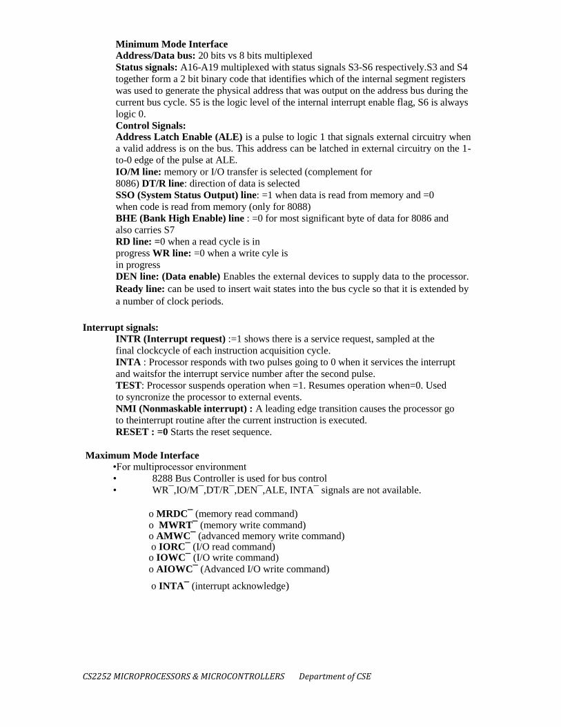
Minimum Mode Interface Address/Data bus: 20 bits vs 8 bits multiplexed Status signals: A16-A19 multiplexed with status signals S3-S6 respectively.S3 and S4
together form a 2 bit binary code that identifies which of the internal segment registers
was used to generate the physical address that was output on the address bus during the
current bus cycle. S5 is the logic level of the internal interrupt enable flag, S6 is always
logic 0. Control Signals: Address Latch Enable (ALE) is a pulse to logic 1 that signals external circuitry when
a valid address is on the bus. This address can be latched in external circuitry on the 1-
to-0 edge of the pulse at ALE. IO/M line: memory or I/O transfer is selected (complement for
8086) DT/R line: direction of data is selected SSO (System Status Output) line: =1 when data is read from memory and =0
when code is read from memory (only for 8088) BHE (Bank High Enable) line : =0 for most significant byte of data for 8086 and
also carries S7 RD line: =0 when a read cycle is in
progress WR line: =0 when a write cyle is
in progress DEN line: (Data enable) Enables the external devices to supply data to the processor.
Ready line: can be used to insert wait states into the bus cycle so that it is extended by
a number of clock periods.
Interrupt signals: INTR (Interrupt request) :=1 shows there is a service request, sampled at the
final clockcycle of each instruction acquisition cycle. INTA : Processor responds with two pulses going to 0 when it services the interrupt
and waitsfor the interrupt service number after the second pulse. TEST: Processor suspends operation when =1. Resumes operation when=0. Used
to syncronize the processor to external events. NMI (Nonmaskable interrupt) : A leading edge transition causes the processor go
to theinterrupt routine after the current instruction is executed. RESET : =0 Starts the reset sequence.
Maximum Mode Interface
•For multiprocessor environment • 8288 Bus Controller is used for bus control • WR¯,IO/M¯,DT/R¯,DEN¯,ALE, INTA¯ signals are not available.
o MRDC¯ (memory read command) o MWRT¯ (memory write command) o AMWC¯ (advanced memory write command) o IORC¯ (I/O read command) o IOWC¯ (I/O write command)
o AIOWC¯ (Advanced I/O write command)
o INTA¯ (interrupt acknowledge)

CS2252 MICROPROCESSORS & MICROCONTROLLERS Department of CSE
3. 8086 Instruction set: Data Transfer:
The MOV instruction is used to transfer 8 and 16-bit data to and from
registers. Either the source or destination has to be a register. The other operand can
come from another register, from memory, from immediate data (a value included in
the instruction) or from a memory location ―pointed at‖ by register BX. For example, if COUNT is the label of a memory location the following
are possible assembly-language instructions : register:
move contents of BX to AX
MOV AX,BX direct: move
contents of AX to memory
MOV COUNT,AX immediate:
load CX with the value 240
MOV CX,0F0H
memory: load CX with the value at address 240
MOV CX,[0F0H]

CS2252 MICROPROCESSORS & MICROCONTROLLERS Department of CSE
register indirect: move contents of AL to memory location in BX
MOV [BX],AL
Most 80x86 assemblers keep track of the type of each symbol and require a type
―override‖ when the symbol is used in a different way. The OFFSET operator to
convert a memory reference to a 16-bit value. For example: MOV BX,COUNT ; load the value at location
COUNT MOV BX,OFFSET COUNT ;
load the offset of COUNT 16 -bit registers can be pushed (the SP is first decremented by two and then the value
stored at SP) or popped (the value is restored from the memory at SP and then SP is
incremented by 2).
For example: PUSH AX ; push contents of AX POP BX ; restore into BX There are some things to note about Intel assembly language syntax: the order of the operands is destination,source —the reverse of that used on the
68000!
semicolons begin a comment
the suffix ’H’ is used to indicate a hexadecimal
constant, if the constant begins with a letter it
must be prefixed with a zero to distinguish it
from a label the suffix ’B’ indicates a binary constant
square brackets indicate accesses to memory
the size of the transfer (byte or word) is determined
by the size of the destination
I/O Operations The 8086 has separate I/O and memory address spaces. Values in the I/O
space are accessed with IN and OUT instructions. The port address is loaded into DX
and the data is read/written to/from AL or AX: MOV DX,372H ; load DX
with port address OUT DX,AL ; output
byte in AL to port ; 372 (hex) IN AX,DX
; input word to AX
Arithmetic/Logic Arithmetic and logic instructions can be performed on byte and 16-bit
values. The first operand has to be a register and the result is stored in that register.

CS2252 MICROPROCESSORS & MICROCONTROLLERS Department of CSE
Control Transfer
Conditional jumps transfer control to another address depending on the values of the
flags in the flag register. Conditional jumps are restricted to a range of -128 to +127 bytes
from the next instruction while unconditional jumps can be to any point.
The assembly-language equivalent of an if statement in a high-level language is a
Compare operation followed by a conditional jump.
The CALL and RET instructions call and return from subroutines. The processor
pushes IP on the stack during a CALL instruction and the contents of IP are popped by
the RET instructions. For example:
CALL readchar ... readchar: ... RET
Segment/Offset Addressing Since address registers and address operands are only 16 bits they can only
address 64k bytes. In order toaddress the 20-bit address range of the 8086, physical
addresses (those that are put on the address bus) are always formed by adding the values
of one of the segment registers to the 16-bit address to forma 20- bit address. The
segment registers themselves only contain the most-significant 16 bits of the 20-bit
value that is contributed by the segment registers. The least significant four bits of the
segment address are always zero. By default, the DS (data segment) is used for data transfer instructions (e.g.
MOV), CS (code segment) is used with control transfer instructions (e.g. JMP or CALL),
and SS is used with the stackpointer (e.g. PUSH or to save/restore addresses during
CALL/RET or INT instructions). The use of segment registers reduces the size of pointers to 16 bits. This
reduces the code size but also restricts the addressing range of a pointer to 64k bytes.
Performing address arithmetic within datastructures larger than 64k is awkward. This is
thebiggest drawback of the 8086 architecture. We will restrict ourselves to short
programs where all of the code, data and stack are placed into the same 64k segment
(i.e. CS=DS=SS).
4. Addressing modes:
Indexed :- 8-bit or 16-bit instruction operand is added to the contents of an index
register (SI or
DI), the resulting value is a pointer to location where data resides.
Based Indexed :- the contents of a base register (BX or BP) is added to the contents of
an index register (SI or DI), the resulting value is a pointer to location where data
resides.
Based Indexed with displacement :- 8-bit or 16-bit instruction operand is added to the
contents of a base register (BX or BP) and index register (SI or DI), the resulting value
is a pointer to location where data resides.
Implied - the data value/data address is implicitly associated with the instruction.
Register - references the data in a register or in a register pair.
Immediate - the data is provided in the instruction.
Direct - the instruction operand specifies the memory address where data is located.

CS2252 MICROPROCESSORS & MICROCONTROLLERS Department of CSE
Register indirect - instruction specifies a register containing an address, where data is
located. This addressing mode works with SI, DI, BX and BP registers. Based :- 8-bit or 16-bit instruction operand is added to the contents of a base register (BX or BP), the resulting value is a pointer to location where data resides. DATA ADDRESSING MODES
• MOV instruction is a common and flexible instruction. – provides a basis for
explanation of data addressing modes
• Figure 1 illustrates the MOV instruction and defines the direction of data flow.
• Source is to the right and destination the left, next to the opcode MOV. – an opcode, or
operation code, tells the microprocessor which operation to perform
• These data-addressing modes are found with all versions of the Intel microprocessor.
– except for the scaled-index-addressing mode, found only in 80386 through Core2
• RIP relative addressing mode is not illustrated. only available on the Pentium 4 and
Core2 in the 64-bit mode.
Register Addressing • The most common form of data addressing. – once register names learned, easiest to apply.
• The microprocessor contains these 8-bit register names used with register addressing: AH, AL,
BH, BL, CH, CL, DH, and DL.
• 16-bit register names: AX, BX, CX, DX, SP, BP, SI, and DI.
• In 80386 & above, extended 32-bit register names are: EAX, EBX, ECX, EDX, ESP, EBP,
EDI, and ESI.
• 64-bit mode register names are: RAX, RBX, RCX, RDX, RSP, RBP, RDI, RSI, and R8 through
R15.
• Important for instructions to use registers that are the same size. – never mix an 8-bit \with a 16-
bit register, an 8- or a 16-bit register with a 32-bit register – this is not allowed by the
microprocessor and results in an error when assembled.

CS2252 MICROPROCESSORS & MICROCONTROLLERS Department of CSE
Immediate Addressing
• Term immediate implies that data immediately follow the hexadecimal opcode in the memory.
– immediate data are constant data – data transferred from a register or memory location are
variable data
• Immediate addressing operates upon a byte or word of data.
• Figure 3–4 shows the operation of a MOV EAX,13456H instruction.
As with the MOV instruction illustrated in Figure 3, the source data overwrites the destination
data. In symbolic assembly language, the symbol # precedes immediate data in some assemblers.
– MOV AX,#3456H instruction is an example
• Most assemblers do not use the # symbol, but represent immediate data as in the MOV
AX,3456H instruction. – an older assembler used with some Hewlett- Packard logic development
does, as may others – in this text, the # is not used for immediate data
The symbolic assembler portrays immediate data in many ways.
• The letter H appends hexadecimal data.
• If hexadecimal data begin with a letter, the assembler requires the data start with a 0. – to
represent a hexadecimal F2, 0F2H is used in assembly language
• Decimal data are represented as is and require no special codes or adjustments. – an example is
the 100 decimal in the MOV AL,100 instruction An ASCII-coded character or characters may

CS2252 MICROPROCESSORS & MICROCONTROLLERS Department of CSE
be depicted in the immediate form if the ASCII data are enclosed in apostrophes. – be careful to
use
the apostrophe („) for ASCII data and not the single quotation mark („)
• Binary data are represented if the binary number is followed by the letter B. – in some
assemblers, the letter Y Each statement in an assembly language program consists of four parts
or fields.
• The leftmost field is called the label. – used to store a symbolic name for the memory location
it represents
• All labels must begin with a letter or one of the following special characters: @, $, -, or ?.
– a label may any length from 1 to 35 characters
• The label appears in a program to identify the name of a memory location for storing data and
for other purposes. The next field to the right is the opcode field. – designed to hold the
instruction, or opcode – the MOV part of the move data instruction is an example of an opcode
• Right of the opcode field is the operand field. – contains information used by the opcode
– the MOV AL,BL instruction has the opcode MOV and operands AL and BL
• The comment field, the final field, contains a comment about the instruction(s). – comments
always begin with a semicolon (;)
Direct Data Addressing:
• Applied to many instructions in a typical program.
• Two basic forms of direct data addressing: – direct addressing, which applies to a MOV
between a memory location and AL, AX, or EAX – displacement addressing, which applies to
almost any instruction in the instruction set
• Address is formed by adding the displacement to the default data segment address or an
alternate segment address.
Direct Addressing • Direct addressing with a MOV instruction transfers data between a memory location, located
within the data segment, and the AL (8-bit), AX (16-bit), or EAX (32-bit) register.
– usually a 3-byte long instruction
• MOV AL,DATA loads AL from the data segment memory location DATA (1234H).
– DATA is a symbolic memory location, while 1234H is the actual hexadecimal location
Displacement Addressing • Almost identical to direct addressing, except the instruction is 4 bytes wide instead of 3.
• In 80386 through Pentium 4, this instruction can be up to 7 bytes wide if a 32-bit register and a
32-bit displacement are specified.
• This type of direct data addressing is much more flexible because most instructions use it.
Register Indirect Addressing • Allows data to be addressed at any memory location through an offset address held in any of the
following registers: BP, BX, DI, and SI.
• In addition, 80386 and above allow register indirect addressing with any extended register
except ESP.
• In the 64-bit mode, the segment registers serve no purpose in addressing a location in the flat
model.

CS2252 MICROPROCESSORS & MICROCONTROLLERS Department of CSE
The data segment is used by default with register indirect addressing or any other mode that uses
BX, DI, or SI to address memory.
• If the BP register addresses memory, the stack segment is used by default. – these settings are
considered the default for these four index and base registers
• For the 80386 and above, EBP addresses memory in the stack segment by default.
• EAX, EBX, ECX, EDX, EDI, and ESI address memory in the data segment by default.
When using a 32-bit register to address memory in the real mode, contents of the register must
never exceed 0000FFFFH.
Base-Plus-Index Addressing • Similar to indirect addressing because it indirectly addresses memory data.
• The base register often holds the beginning location of a memory array. – the index
register holds the relative position of an element in the array – whenever BP addresses
memory data, both the stack segment register and BP generate the effective address.
Locating Data with Base-Plus-Index Addressing • The Intel assembler requires this addressing mode appear as [BX][DI] instead of [BX
+ DI].
• The MOV DX,[BX + DI] instruction is MOV DX,[BX][DI] for a program written for
the Intel ASM assembler.

CS2252 MICROPROCESSORS & MICROCONTROLLERS Department of CSE
Plus-Index Addressing • A major use is to address elements in a memory array.
• To accomplish this, load the BX register (base) with the beginning address of the array and the
DI register (index) with the element number to be accessed.
5. Assembler directives:
ASSUME DB - Defined Byte.
DD - Defined Double Word DQ - Defined Quad Word
DT - Define Ten Bytes
DW - Define Word ASSUME Directive - The ASSUME directive is used to tell the assembler that the name of the
logical segment should be used for a specified segment. The 8086 works directly with only 4
physical segments: a Code segment, a data segment, a stack segment, and an extra segment.

CS2252 MICROPROCESSORS & MICROCONTROLLERS Department of CSE
Example: ASUME CS:CODE ;This tells the assembler that the logical segment named CODE contains
the instruction statements for the program and should be treated as a codesegment. ASUME DS:DATA ;This tells the assembler that for any instruction which refers to a data in
the datasegment, data will found in the logical segment DATA. DB - DB directive is used to declare a bytetype variable or to store a byte in memory location. Example: 1. PRICE DB 49h, 98h, 29h ;Declare an array of 3 bytes, named as PRICE and initialize. 2. NAME DB ‘ABCDEF’ ;Declare an array of 6 bytes and initialize with ASCII code for letters
3. TEMP DB 100 DUP(?) ;Set 100 bytes of storage in memoryand give it the name as TEMP, but leave the 100 bytes uninitialized. Program instructions will load values into these locations. DW - The DW directive is used to define a variable of type word or to reserve storage location of
type word in memory. Example: MULTIPLIER DW 437Ah ; this declares a variable of type word and named it as
MULTIPLIER. This variable is initialized with the value 437Ah when it is loaded into memory to
run. EXP1 DW 1234h, 3456h, 5678h ; this declares an array of 3 words and initialized with specified
values. STOR1 DW 100 DUP(0); Reserve an array of 100 words of memory and initialize all words
with 0000.Array is named as STOR1. END - END directive is placed after the last statement of a program to tell the assembler that this
is the end of the program module. The assembler will ignore any statement after an END
directive. Carriage return is required after the END directive. ENDP - ENDP directive is used along with the name of the procedure to indicate the end of a
procedure to the assembler. Example: SQUARE_NUM PROCE ; It start the procedure ;Some steps to find the square root of a number
SQUARE_NUM ENDP ;Hear it is the End for the procedure. END - End Program ENDP - End Procedure ENDS - End Segment EQU - Equate EVEN - Align on Even Memory Address
EXTRN ENDS - This ENDS directive is used with name of the segment to indicate the end of that logic
segment. Example: CODE SEGMENT ;Hear it Start the logic segment containing code Some instructions
statements to perform the logical operation. CODE ENDS ;End of segment named as CODE EQU - This EQU directive is used to give a name to some value or to a symbol. Each time the
assembler finds the name in the program, it will replace the name with the value or symbol you
given to that name. Example: FACTOR EQU 03H ; you has to write this statement at the starting of your program and later
in the program you can use this as follows ADD AL, FACTOR ; When it codes this instruction the assembler will code it as ADDAL, 03H

CS2252 MICROPROCESSORS & MICROCONTROLLERS Department of CSE
The advantage of using EQU in this manner is, if FACTOR is used many no of times in a
program and you want to change the value, all you had to do is change the EQU statement at
beginning, it will changes the rest of all. EVEN - This EVEN directive instructs the assembler to increment the location of the counter to
the next even address if it is not already in the even address. If the word is at even address 8086
can read a memory in 1 bus cycle.If the word starts at an odd address, the 8086 will take 2 bus
cycles to get the data. A series of words can be read much more quickly if they are at even
address. When EVEN is used the location counter will simply incremented to next address and
NOP instruction is inserted in that incremented location. Example: DATA1 SEGMENT ; Location counter will point to 0009 after assembler reads next statement
SALES DB 9 DUP(?) ;declare an array of 9 bytes EVEN ; increment location counter to 000AH RECORD DW 100 DUP( 0 ) ;Array of 100 words will start from an even address for quicker
read DATA1 ENDS GROUP - Group Related Segments LABLE NAME OFFSET ORG – Originate GROUP - The GROUP directive is used to group the logical segments named after the directive
into one logical group segment. INCLUDE - This INCLUDE directive is used to insert a block of source code from the named
file into the current source module. PROC - Procedure PTR - Pointer PUBLC SEGMENT SHORT TYPE PROC - The PROC directive is used to identify the start of a procedure. The term near or far is
used to specify the type of the procedure. Example: SMART PROC FAR ; This identifies that the start of a procedure named as SMART and
instructs the assembler that the procedure is far . SMART ENDP This PROC is used with ENDP to indicate the break of the procedure. PTR - This PTR operator is used to assign a specific type of a variable or to a label. Example: INC [BX] ; This instruction will not know whether to increment the byte pointed to by BX or a
word pointed to by BX. INC BYTE PTR [BX] ;increment the byte pointed to by BX This PTR operator can also be
used to override the declared type of variable . If we want to access the a byte in an array WORDS DW 437Ah, 0B97h, MOV AL, BYTE PTR WORDS PUBLIC - The PUBLIC directive is used to instruct the assembler that a specified name or
label will be accessed from other modules. Example:

CS2252 MICROPROCESSORS & MICROCONTROLLERS Department of CSE
PUBLIC DIVISOR, DIVIDEND ;these two variables are public so these are available to all
modules. If an instruction in a module refers to a variable in another assembly module, we can
access that module by declaring as EXTRN directive. TYPE - TYPE operator instructs the assembler to determine the type of a variable and
determines the number of bytes specified to that variable. Example: Byte type variable – assembler will give a value 1 Word type variable – assembler will give a
value 2 Double word type variable – assembler will give a value 4 ADD BX, TYPE WORD_ ARRAY ; hear we want to increment BX to point to next word in an
array of words.
6. Macros:
Macros are just like procedures, but not really. Macros =ook like procedures, but they exist only
until your code is compiled, after = compilation all macros are replaced with real instructions. If
you = declared a macro and never used it in your code, compiler will =imply ignore it.
emu8086.inc is a good example of how macros can be used, this file contains =everal macros to
make coding easier for you. Macro definition:
name MACRO [parameters,...]
<instructions>
ENDM Unlike procedures, macros should be defined above the code that uses it, for example: = MyMacro MACRO p1, p2, p3
MOV AX, p1
MOV BX, p2
MOV CX, p3
ENDM
ORG 100h
MyMacro 1, 2, 3
MyMacro 4, 5, DX
RET

CS2252 MICROPROCESSORS & MICROCONTROLLERS Department of CSE
The above code is expanded into:
MOV AX, 00001h MOV =X, 00002h MOV CX, 00003h MOV AX, 00004h
MOV BX, =0005h MOV CX, DX Some important facts about macros and procedures:
When you want to use a procedure you should use =B>CALL instruction, for example:
CALL MyProc =/FONT>
When you want to use a macro, you can just type its =ame. For example: MyMacro
=/FONT>
Procedure is located at some specific address in memory, and if you use the same
procedure 100 times, the CPU will transfer control to this part of the memory. The
control will be returned back to the program by RET instruction. The =B>stack is used
to keep the return address. The CALL instruction takes about 3 bytes, so the size of the
output executable file =rows very insignificantly, no matter how many time the
procedure is used.
Macro is expanded directly in program's code. So if =ou use the same macro 100 times,
the compiler expands the macro =00 times, making the output executable file larger and
larger, each time all instructions of a macro are inserted.
You should use stack or any general purpose registers to pass parameters to procedure.
To pass parameters to macro, you can just type them after the macro name. For example:
MyMacro 1, 2, 3
To mark the end of the macro ENDM directive is enough.
To mark the end of the procedure, you should type the same of the procedure before the
ENDP directive.

CS2252 MICROPROCESSORS & MICROCONTROLLERS Department of CSE
Macros are expanded directly in code, therefore if there are labels inside the macro definition
you may get "Duplicate declaration" error when macro is used for twice or more. To avoid such
problem, use LOCAL directive followed by names of variables, labels or procedure names. For
example:
MyMacro2 MACRO
LOCAL label1, label2
CMP AX, 2 JE label1 CMP AX, 3 JE label2 label1:
INC AX label2:
ADD AX, 2 ENDM
ORG 100h MyMacro2
7. Interrupts band interrupts service routines: INTERRUPTS
There are two main types of interrupt in the 8086 microprocessor, internal and external
hardware interrupts. Hardware interrupts occur when a peripheral device asserts an interrupt input
pin of the microprocessor. Whereas internal interrupts are initiated by the state of the CPU (e.g.
divide by zero error) or by an instruction.
Provided the interrupt is permitted, it will be acknowledged by the processor at the end of
the current memory cycle. The processor then services the interrupt by branching to a special
service routine written to handle that particular interrupt. Upon servicing the device, the processor
is then instructed to continue with what is was doing previously by use of the "return from
interrupt" instruction.
The status of the programme being executed must first be saved. The processors registers
will be saved on the stack, or, at very least, the programme counter will be saved. Preserving
those registers which are not saved will be the responsibility of the interrupt service routine. Once
the programme counter has been saved, the processor will branch to the address of the service
routine. Edge or Level sensitive Interrupts
Edge level interrupts are recognised on the falling or rising edge of the input signal. They
are generally used for high priority interrupts and are latched internally inside the processor. If
this latching was not done, the processor could easily miss the falling edge (due to its short
duration) and thus not respond to the interrupt request.
Level sensitive interrupts overcome the problem of latching, in that the requesting device
holds the interrupt line at a specified logic state (normally logic zero) till the processor

CS2252 MICROPROCESSORS & MICROCONTROLLERS Department of CSE
acknowledges the interrupt. This type of interrupt can be shared by other devices in a wired 'OR'
configuration, which is commonly used to support daisy chaining and other techniques.
Maskable Interrupts The processor can inhibit certain types of interrupts by use of a special interrupt mask bit.
This mask bit is part of the flags/condition code register, or a special interrupt register. In the
8086 microprocessor if this bit is clear, and an interrupt request occurs on the Interrupt Request
input, it is ignored. Non-Maskable Interrupts
There are some interrupts which cannot be masked out or ignored by the processor. These
are associated with high priority tasks which cannot be ignored (like memory parity or bus faults).
In general, most processors support the Non-Maskable Interrupt (NMI). This interrupt has
absolute priority, and when it occurs, the processor will finish the current memory cycle, then
branch to a special routine written to handle the interrupt request. Advantages of Interrupts
Interrupts are used to ensure adequate service response times by the processing.
Sometimes, with software polling routines, service times by the processor cannot be guaranteed,
and data may be lost. The use of interrupts guarantees that the processor will service the request
within a specified time period, reducing the likelihood of lost data. Interrupt Latency
The time interval from when the interrupt is first asserted to the time the CPU recognises
it. This will depend much upon whether interrupts are disabled, prioritized and what the processor
is currently executing. At times, a processor might ignore requests whilst executing some
indivisible instruction stream (read-write-modify cycle). The figure that matters most is the
longest possible interrupt latency time. Interrupt Response Time
The time interval between the CPU recognising the interrupt to the time when the first
instruction of the interrupt service routine is executed. This is determined by the processor
architecture and clock speed.
The Operation of an Interrupt sequence on the 8086 Microprocessor: 1. External interface sends an interrupt signal, to the Interrupt Request (INTR) pin, or an internal interrupt occurs. 2. The CPU finishes the present instruction (for a hardware interrupt) and sends Interrupt Acknowledge (INTA) to hardware interface. 3. The interrupt type N is sent to the Central Processor Unit (CPU) via the Data bus from the hardware interface.
4. The contents of the flag registers are pushed onto the stack.
5. Both the interrupt (IF) and (TF) flags are cleared. This disables the INTR pin and the trap or
single-step feature.
6. The contents of the code segment register (CS) are pushed onto the Stack.
7.The contents of the instruction pointer (IP) are pushed onto the Stack.
8.The interrupt vector contents are fetched, from (4 x N) and then placed into the IP and from (4 x
N +2) into the CS so that the next instruction executes at the interrupt service procedure
addressed by the interrupt vector.
While returning from the interrupt-service routine by the Interrupt Return (IRET)
instruction, the IP, CS and Flag registers are popped from the Stack and return to their state prior
to the interrupt.

CS2252 MICROPROCESSORS & MICROCONTROLLERS Department of CSE
Multiple Interrupts If more than one device is connected to the interrupt line, the processor needs to know to which
device service routine it should branch to. The identification of the device requesting service can
be done in either hardware or software, or a combination of both. The three main methods are:
1. Software Polling, 2. Hardware Polling, (Daisy Chain), 3. Hardware Identification (Vectored Interrupts).
Software Polling Determination of the Requesting Device
A software routine is used to identify the device requesting service. A simple polling
technique is used, each device is checked to see if it was the one needing service.
Having identified the device, the processor then branches to the appropriate interrupt -
handling-routine address for the given device. The order in which the devices appear in the
polling sequence determines their priority.

CS2252 MICROPROCESSORS & MICROCONTROLLERS Department of CSE
8. BIOS function calls:
AH 00H :Terminate a Program AH 01H : Read the Keyboard AH 02H : Write to a Standard Output Device
AH 08H : Read a Standard Input without Echo
AH 09H : Display a Character String 9. AH 0AH : Buffered keyboard Input
INT 21H : Call BIOS Function
9. Assembly language programming:
Instruction Execution
Fetch/Decode/Execute cycle is like a program: Repeat
Fetch instruction from primary memory
Increment Program Counter
Decode
Fetch operands from memory (if required) Execute instruction
Write results to memory (if required) Until Halt
How is this "program" written?
Eg. ADD Instruction
1. Fetch operand1, store in register X
2. Fetch operand2, store in register Y
3. Tell ALU to add X and Y
4. Put result in ACC
MICROCODE
• Lowest level of software
• Flexible: can be updated by designers
• Controls the digital logic of the CPU
• Implements the machine code instructions

CS2252 MICROPROCESSORS & MICROCONTROLLERS Department of CSE
1. ALP to add list of 10 given numbers title ALP to add list of 10 given numbers dosseg
.model small
.stack 100
.code
main proc
mov ax, @data mov ds, ax mov, cx, 0aH mov dx, 00
mov SI, offset array1
BACK: add dl, SI
adc dh, 00
LOOP back mov result, dx mov ax, 4c00h INT 21h
main endp
.data
array1 db 01, 02, 03, 04, 05, 06, 07, 08, 09, 10
result db ?
end main
2. SUM THE NUMBERS FROM 1-100
title SUM THE NUMBERS FROM 1-100
dosseg
.model small
.stack 100H
.code
main proc mov ax, 0
mov cx, 10h ; loop count=10
BACK: add ax, cx ; add two numbers loop BACK ; repeat until cx=0
mov ax, 4c00h ; return to DOS
int 21h main endp
end main
3. An Example Of Keyboard Intercept Now we need to write and test a routine for printing a message to the display. For this, we‟ll
use DOS function call 9, which prints a string to the video display.
.Data mesg db
'Ten seconds have passed!',0Dh, 0Ah,'$' ;
; pmesg - Prints the message pointed to by the DX register on the screen.;
pmesg PROC mov
ah, 09h
;DOS Print to screen function. int
21h
;Call DOS. ret
;Return after printing. pmesg
ENDP
;Test our procedure for printing a message. start: mov
ax, @Data ;We're using the data segment now so we mov
ds, ax
; need to initialize it!
.Code end
mov call call call mov int
start

CS2252 MICROPROCESSORS & MICROCONTROLLERS Department of CSE
dx, offset mesg;Point DX at the message. pmesg
;Print the message on the screen. pmesg
; a few times. pmesg
;
ax, 4C00h
;DOS Exit function call, return code 0.
21h
;Call DOS to exit.

CS2252 MICROPROCESSORS & MICROCONTROLLERS Department of CSE

CS2252 – MICROPROCESSORS & MICROCONTROLLERS Department of CSE 32