UNIT I UNIT I INDETERMINATE FRAMES 9 S.NO 2 MARKS …UNIT – I UNIT I INDETERMINATE FRAMES 9 Degree...
87
CE6501 – STRUCTURAL ANALYSIS 1 DEPARTMENT OF CIVIL ENGINEERING/ UNIT – I UNIT I INDETERMINATE FRAMES 9 Degree of static and kinematic indeterminacies for plane frames - analysis of indeterminate pin-jointed frames - rigid frames (Degree of statical indeterminacy up to two) - Energy and consistent deformation methods. S.NO 2 MARKS PAGE NO 1 Why it is necessary to compute deflections in structures? 4 2 What is meant by ‘cambering technique, in structures? 4 3 Name any four methods used for the computation of deflections in structures. 4 4 State the difference between strain energy method and unit load method in the determination of deflection of structures. 4 5 What are the assumptions made in the unit load method? 4 6 Give the equation that is used for the determination of deflection at a given point i in beams and frames. 4 7 The horizontal displacement of the end D of the portal frame is required. Determine the relevant equations due to the unit load at appropriate point. 5 8 Due to load at B in the truss in fig. the forces in the members are as under. Determine the horizontal displacement of B by unit load method. 5 9 Determine the rotation of the curved beam in fig. due to a moment Mo, by unit load method. 6 10 State the Principle of Virtual work. 6 11 Sketch the Williot’s Diagram for the truss in fig. to find ∆B. 6 12 What is the strain energy stored in a rod of length l and axial rigidity AE to an axial force P? 7 13 Define Virtual work. 7 14 Explain the procedure involved in the deflection of pin jointed plane frames. 7 15 In the truss shown in fig. no load acts. The member AB gets 4mm too short. The cross sectional area of each member is A = 300 mm 2 and E = 200 GPa. Determine the vertical displacement of joint C. 7 16 Using the method of virtual work, determine the vertical displacement of point B of the beam shown in fig. Take E = 2x 10 5 MPa and I = 825x 10 7 mm 4 . 8 17 Table shows the lengths and deformations of the members of the cantilever truss, shown in fig. Construct a Williot’ diagram and tabulate the displacement of nodes. 9
Transcript of UNIT I UNIT I INDETERMINATE FRAMES 9 S.NO 2 MARKS …UNIT – I UNIT I INDETERMINATE FRAMES 9 Degree...
CE6501 – STRUCTURAL ANALYSIS
1
DEPARTMENT OF CIVIL ENGINEERING/
UNIT – I
UNIT I INDETERMINATE FRAMES 9 Degree of static and kinematic
indeterminacies for plane frames - analysis of indeterminate pin-jointed frames - rigid
frames (Degree of statical indeterminacy up to two) - Energy and consistent
deformation methods.
S.NO 2 MARKS PAGE NO
1 Why it is necessary to compute deflections in structures? 4
2 What is meant by ‘cambering technique, in structures? 4
3 Name any four methods used for the computation of deflections
in structures. 4
4 State the difference between strain energy method and unit load
method in the determination of deflection of structures. 4
5 What are the assumptions made in the unit load method? 4
6 Give the equation that is used for the determination of deflection
at a given point i in beams and frames. 4
7 The horizontal displacement of the end D of the portal frame is
required. Determine the relevant equations due to the unit load at
appropriate point.
5
8 Due to load at B in the truss in fig. the forces in the members are
as under. Determine the horizontal displacement of B by unit
load method.
5
9 Determine the rotation of the curved beam in fig. due to a
moment Mo, by unit load method. 6
10 State the Principle of Virtual work. 6
11 Sketch the Williot’s Diagram for the truss in fig. to find ∆B. 6
12 What is the strain energy stored in a rod of length l and axial
rigidity AE to an axial force P? 7
13 Define Virtual work. 7
14 Explain the procedure involved in the deflection of pin jointed
plane frames. 7
15
In the truss shown in fig. no load acts. The member AB gets
4mm too short. The cross sectional area of each member is A =
300 mm2 and E = 200 GPa. Determine the vertical displacement
of joint C.
7
16
Using the method of virtual work, determine the vertical
displacement of point B of the beam shown in fig. Take E = 2x
105 MPa and I = 825x 107 mm4.
8
17
Table shows the lengths and deformations of the members of the
cantilever truss, shown in fig. Construct a Williot’ diagram and
tabulate the displacement of nodes.
9
CE6501 – STRUCTURAL ANALYSIS
2
DEPARTMENT OF CIVIL ENGINEERING/
S.NO 16 MARKS PAGE NO
1 Determine the vertical displacement of joint C of the steel truss
shown in fig. The cross sectional area of each member is A =
400 mm2 and E = 2*105 N/mm2.
11
2 Using the principle of virtual work, determine the vertical and
horizontal deflection components of joint C of the truss in fig. A
= 150*10-6 m2 and E = 200*106 kN/m2
15
3
Determine the vertical and horizontal displacements of the point
C of the pin-jointed frame shown in fig. The cross sectional area
of AB is 100 sqmm and of AC and BC 150 mm2 each. E= 2 x 10 5 N/mm2. (By unit load method)
18
4 Using the principle of least work, analyze the portal frame
shown in Fig. 20
5
Using the method of virtual work, determine the horizontal
displacement of support D of the frame shown in fig. The values
of I are indicated along the members. Take E = 200 x 106 KN/m2
and I = 300 x 10-6 m4.
23
6
Using the method of virtual work, determine the horizontal
displacement of support D of the frame shown in fig. The values
of I are indicated along the members. Take E = 200 x 106 KN/m2
and I = 300 x 10-6 m4.
24
7
Using the method of virtual work, determine the horizontal
displacement of support D of the frame shown in fig. The values
of I are indicated along the members. Take E = 200 x 106 KN/m2
and I = 300 x 10-6 m4.
2 6
CE6501 – STRUCTURAL ANALYSIS
3
DEPARTMENT OF CIVIL ENGINEERING/
UNIT – I
TWO MARKS QUESTIONS AND ANSWERS
1. Why it is necessary to compute deflections in structures? Computation of deflection of structures is necessary for the following
reasons:
(i) If the deflection of a structure is more than the permissible, the structure will
not look aesthetic and will cause psychological upsetting of thje occupants.
(ii) Excessive deflection may cause cracking in the materials attached to the
structure. For example, if the deflection of a floor beam is excessive, the floor finishes
and partition walls supported on the beam may get cracked and unserviceable.
2. What is meant by ‘cambering technique, in structures?
Cambering is a technique applied on site, in which a slight upward
curve is made in the structure / beams during construction, so that it will straighten out
and attain the straight shape during loading. This will considerably reduce the
downward deflection that may occur at later stages.
3. Name any four methods used for the computation of deflections in
structures.
(i) Virtual work method – Dummy unit load method
(ii) Strain energy method
(iii) Willot Mohr diagram method
(iv) Method of elastic weights
4. State the difference between strain energy method and unit load method in
the determination of deflection of structures.
In strain energy method, an imaginary load P is applied at the point
where the deflection is desired to be determined. P is equated to Zero in the final step
and the deflection is obtained.
In unit load method, an unit load (instead of P) is applied at the point
where the deflection is desired.
5. What are the assumptions made in the unit load method?
Assumptions made in unit load method are
1. The external and internal forces are in equilibrium
2. Supports are rigid and no movement is possible.
3. The material is strained well within elastic limit.
6. Give the equation that is used for the determination of deflection at a given
point i in beams and frames.
Deflection at a point i is given by,
l
xxi
EI
dxmM
0
CE6501 – STRUCTURAL ANALYSIS
4
DEPARTMENT OF CIVIL ENGINEERING/
Where Mx = moment at a section X due to the applied loads
Mx = moment at a section X due to unit load applied at the point i and
in the direction of the desired dicplacement
EI = flexural rigidity
11. State the Principle of Virtual work.
It states that the work done on a structure by external loads is equal to the
internal energy stored in a structure (Ue = Ui)
Work of external loads = work of internal loads
12. What is the strain energy stored in a rod of length l and axial rigidity AE
to an axial force P?
Strain energy stored
P2 L
U= --------
2AE
13. Define Virtual work.
The term virtual work means the work done by a real force acting
through a virtual displacement or a virtual force acting through a real displacement.
The virtual work is not a real quantity but an imaginary one.
14. Explain the procedure involved in the deflection of pin jointed plane
frames.
1. Virtual forces k: Remove all the real loads from the truss. Place a
unit load on the truss at the joint and in the direction of the desired displacement. Use
the method of joints or the method of sections and calculate the internal forces k in
each member of the truss.
2. Real forces F: These forces arre caused only by the real loads acting
on the truss. Use the method of sections or the method of joints to determine the forces
F in each member.
3. Virtual work equation: Apply the equation of virtual work, to
determine the desired displacement.
15. In the truss shown in fig. no load acts. The member AB gets 4mm too
short. The cross sectional area of each member is A = 300 mm2 and E = 200 GPa.
Determine the vertical displacement of joint C.
CE6501 – STRUCTURAL ANALYSIS
5
DEPARTMENT OF CIVIL ENGINEERING/
Solution:
Virtual forces, k:
Since the vertical displacement of joint C is required, a vertical
force of 1 kN is applied at C. The force k in each member is determined as below:
By symmetry, RA = RB = ½
Joint A: ∑V = 0 gives
KAC cos 36º 52’ + ½ = 0
KAC = 0.625 kN (comp)
∑H = 0 gives
kAB + kAC cos 53º 08’ = 0
kAB = 0.375 kN (tensile)
Joint B: ∑V = 0 gives
KBC cos 36º 52’ + ½ = 0
KBC = 0.625 kN (comp)
Member AB undergoes a deformation, ∆L = 0.004 m
∆ = ∑(k.∆L)
(∆C)V = (0.375) (-0.004) + 0 +0 = -0.0015m = -1.5 mm
The negative sign indicates that joint C displaced upward, i.e. opposite to the
1 kN vertical load.
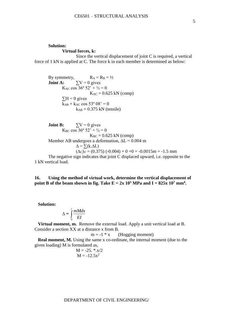
16. Using the method of virtual work, determine the vertical displacement of
point B of the beam shown in fig. Take E = 2x 10⁵ MPa and I = 825x 107 mm4.
Solution:
∆ = l
EI
mMdx
0
Virtual moment, m. Remove the external load. Apply a unit vertical load at B.
Consider a section XX at a distance x from B.
m = -1 * x (Hogging moment)
Real moment, M. Using the same x co-ordinate, the internal moment (due to the
given loading) M is formulated as,
M = -25. *.x/2
M = -12.5x2
CE6501 – STRUCTURAL ANALYSIS
6
DEPARTMENT OF CIVIL ENGINEERING/
Virtual work equation.
(∆B)V = l
EI
mMdx
0
=
12
0
12
0
32 5.12)5.12)(*1(dx
EI
x
EI
dxxx
= EIEIx
x
EIx
x 64800
4
125.12
4
5.12 412
0
4
=
mmormxx
3.39)(0393.01082510*2
64800
58
Hence the vertical displacement of point B = 39.3 mm
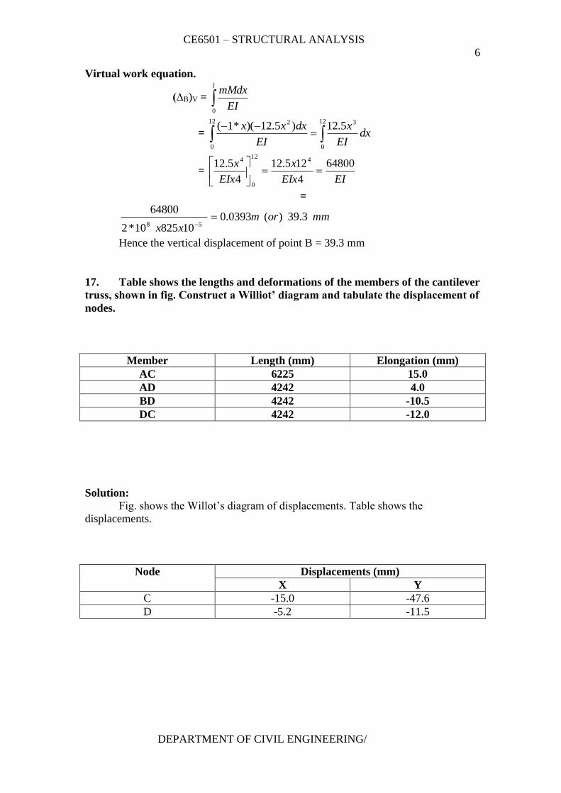
17. Table shows the lengths and deformations of the members of the cantilever
truss, shown in fig. Construct a Williot’ diagram and tabulate the displacement of
nodes.
Member Length (mm) Elongation (mm)
AC 6225 15.0
AD 4242 4.0
BD 4242 -10.5
DC 4242 -12.0
Solution:
Fig. shows the Willot’s diagram of displacements. Table shows the
displacements.
Node Displacements (mm)
X Y
C -15.0 -47.6
D -5.2 -11.5
CE6501 – STRUCTURAL ANALYSIS
7
DEPARTMENT OF CIVIL ENGINEERING/
SIXTEEN MARKS QUESTIONS AND ANSWERS
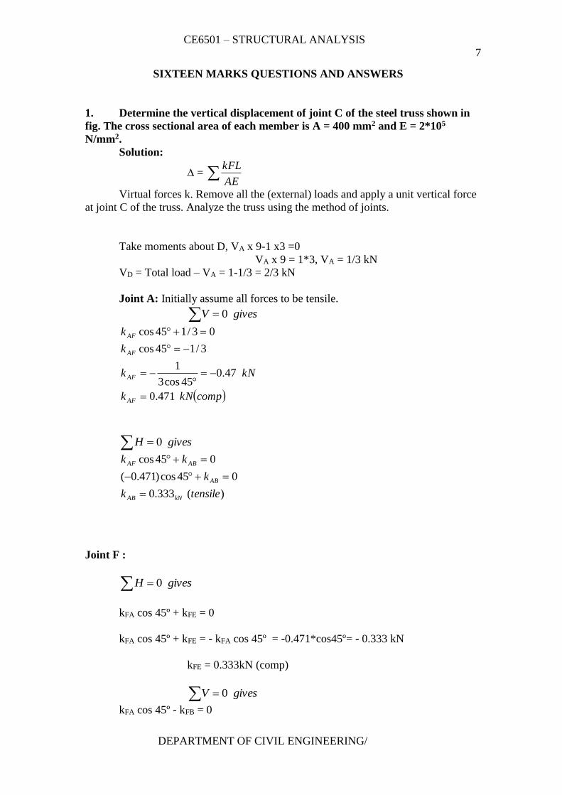
1. Determine the vertical displacement of joint C of the steel truss shown in
fig. The cross sectional area of each member is A = 400 mm2 and E = 2*105
N/mm2.
Solution:
∆ = AE
kFL
Virtual forces k. Remove all the (external) loads and apply a unit vertical force
at joint C of the truss. Analyze the truss using the method of joints.
Take moments about D, VA x 9-1 x3 =0
VA x 9 = 1*3, VA = 1/3 kN
VD = Total load – VA = 1-1/3 = 2/3 kN
Joint A: Initially assume all forces to be tensile.
givesV 0
compkNk
kNk
k
k
AF
AF
AF
AF
471.0
47.045cos3
1
3/145cos
03/145cos
givesH 0
)(333.0
045cos)471.0(
045cos
tensilek
k
kk
kNAB
AB
ABAF
Joint F :
givesH 0
kFA cos 45º + kFE = 0
kFA cos 45º + kFE = - kFA cos 45º = -0.471*cos45º= - 0.333 kN
kFE = 0.333kN (comp)
givesV 0
kFA cos 45º - kFB = 0
CE6501 – STRUCTURAL ANALYSIS
8
DEPARTMENT OF CIVIL ENGINEERING/
kFA cos 45º = kFB
0.471 cos 45º = kFB
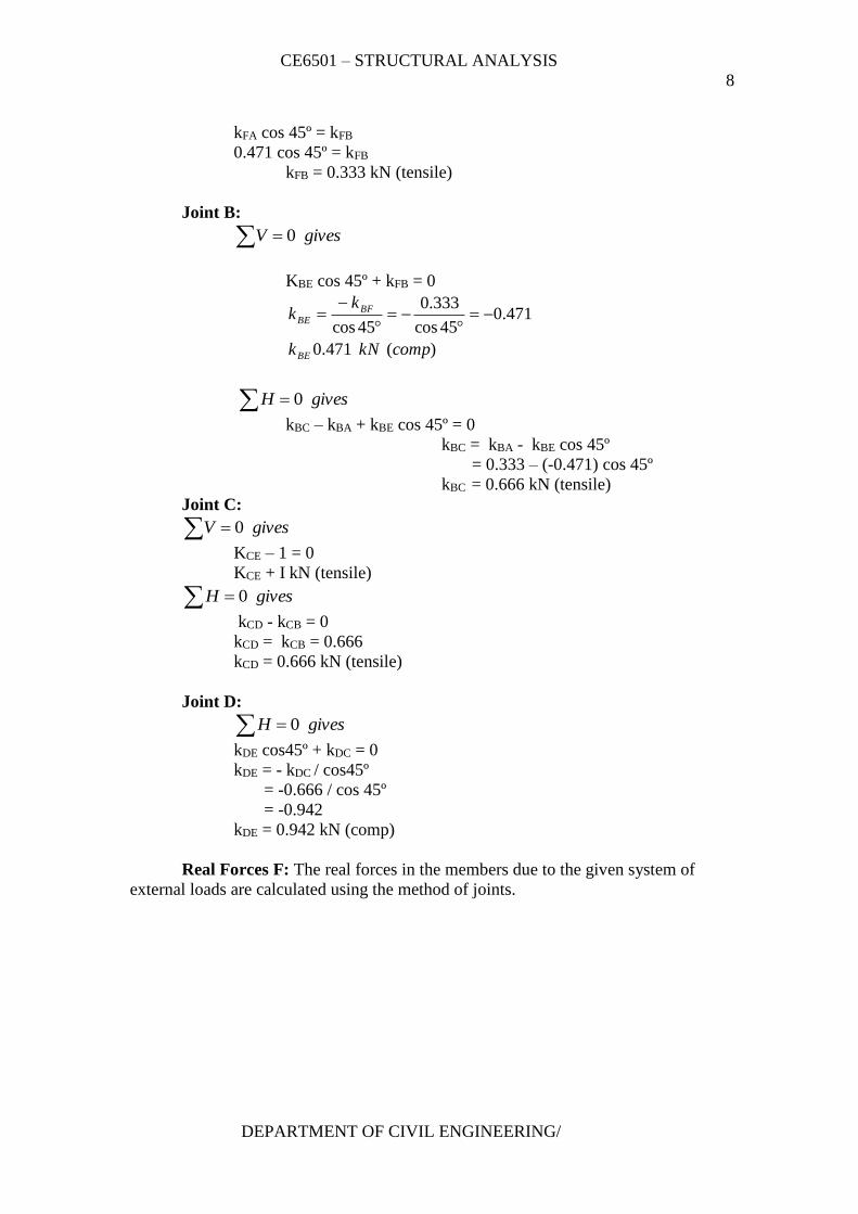
kFB = 0.333 kN (tensile)
Joint B:
givesV 0
KBE cos 45º + kFB = 0
)(471.0
471.045cos
333.0
45cos
compkNk
kk
BE
BFBE
givesH 0
kBC – kBA + kBE cos 45º = 0
kBC = kBA - kBE cos 45º
= 0.333 – (-0.471) cos 45º
kBC = 0.666 kN (tensile)
Joint C:
givesV 0
KCE – 1 = 0
KCE + I kN (tensile)
givesH 0
kCD - kCB = 0
kCD = kCB = 0.666
kCD = 0.666 kN (tensile)
Joint D:
givesH 0
kDE cos45º + kDC = 0
kDE = - kDC / cos45º
= -0.666 / cos 45º
= -0.942
kDE = 0.942 kN (comp)
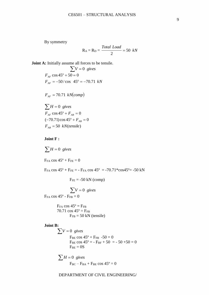
Real Forces F: The real forces in the members due to the given system of
external loads are calculated using the method of joints.
CE6501 – STRUCTURAL ANALYSIS
9
DEPARTMENT OF CIVIL ENGINEERING/
By symmetry
RA = RD = kNLoadTotal
502
Joint A: Initially assume all forces to be tensile.
givesV 0
compkNF
kNF
F
AF
AF
AF
71.70
71.7045cos/50
05045cos
givesH 0
)(50
045cos)71.70(
045cos
tensilekNF
F
FF
AB
AB
ABAF
Joint F :
givesH 0
FFA cos 45º + FFE = 0
FFA cos 45º + FFE = - FFA cos 45º = -70.71*cos45º= -50 kN
FFE = -50 kN (comp)
givesV 0
FFA cos 45º - FFB = 0
FFA cos 45º = FFB
70.71 cos 45º = FFB
FFB = 50 kN (tensile)
Joint B:
givesV 0
FBE cos 45º + FFB -50 = 0
FBE cos 45º = - FBF + 50 = - 50 +50 = 0
FBE = 0S
givesH 0
FBC – FBA + FBE cos 45º = 0
CE6501 – STRUCTURAL ANALYSIS
10
DEPARTMENT OF CIVIL ENGINEERING/
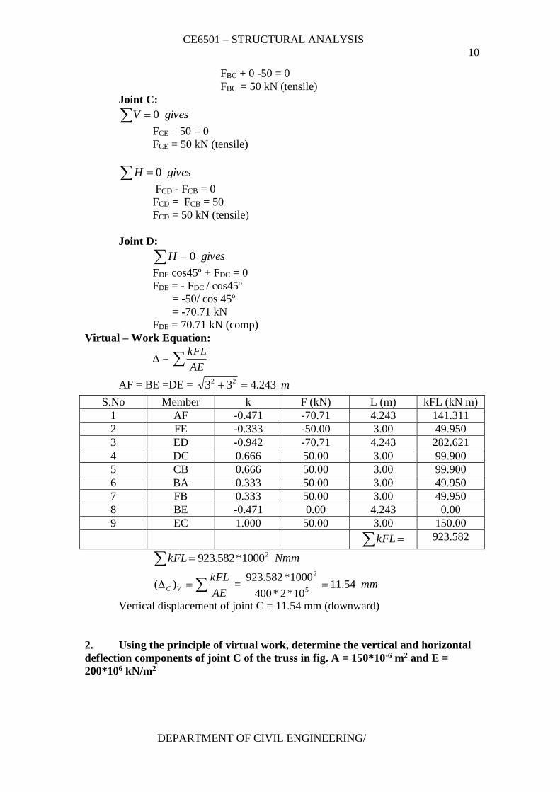
FBC + 0 -50 = 0
FBC = 50 kN (tensile)
Joint C:
givesV 0
FCE – 50 = 0
FCE = 50 kN (tensile)
givesH 0
FCD - FCB = 0
FCD = FCB = 50
FCD = 50 kN (tensile)
Joint D:
givesH 0
FDE cos45º + FDC = 0
FDE = - FDC / cos45º
= -50/ cos 45º
= -70.71 kN
FDE = 70.71 kN (comp)
Virtual – Work Equation:
∆ = AE
kFL
AF = BE =DE = m243.433 22
S.No Member k F (kN) L (m) kFL (kN m)
1 AF -0.471 -70.71 4.243 141.311
2 FE -0.333 -50.00 3.00 49.950
3 ED -0.942 -70.71 4.243 282.621
4 DC 0.666 50.00 3.00 99.900
5 CB 0.666 50.00 3.00 99.900
6 BA 0.333 50.00 3.00 49.950
7 FB 0.333 50.00 3.00 49.950
8 BE -0.471 0.00 4.243 0.00
9 EC 1.000 50.00 3.00 150.00
kFL 923.582
NmmkFL 21000*582.923
VC )( AE
kFL = mm54.11
10*2*400
1000*582.9235
2
Vertical displacement of joint C = 11.54 mm (downward)
2. Using the principle of virtual work, determine the vertical and horizontal
deflection components of joint C of the truss in fig. A = 150*10-6 m2 and E =
200*106 kN/m2
CE6501 – STRUCTURAL ANALYSIS
11
DEPARTMENT OF CIVIL ENGINEERING/
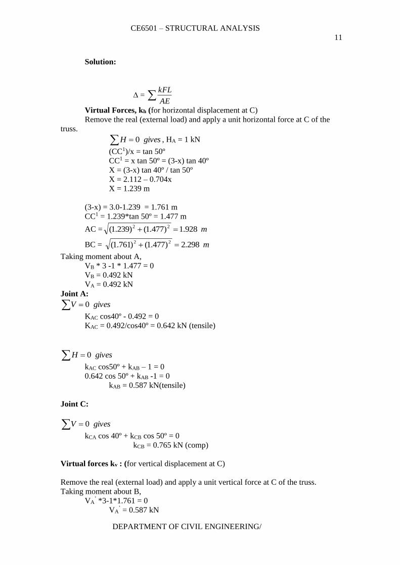
Solution:
∆ = AE
kFL
Virtual Forces, kh (for horizontal displacement at C)
Remove the real (external load) and apply a unit horizontal force at C of the
truss.
givesH 0 , HA = 1 kN
(CC1)/x = tan 50º
CC1 = x tan 50º = (3-x) tan 40º
X = (3-x) tan 40º / tan 50º
X = 2.112 – 0.704x
X = 1.239 m
(3-x) = 3.0-1.239 = 1.761 m
CC1 = 1.239*tan 50º = 1.477 m
AC = m928.1)477.1()239.1( 22
BC = m298.2)477.1()761.1( 22
Taking moment about A,
VB * 3 -1 * 1.477 = 0
VB = 0.492 kN
VA = 0.492 kN
Joint A:
givesV 0
KAC cos40º - 0.492 = 0
KAC = 0.492/cos40º = 0.642 kN (tensile)
givesH 0
kAC cos50º + kAB – 1 = 0
0.642 cos 50º + kAB -1 = 0
kAB = 0.587 kN(tensile)
Joint C:
givesV 0
kCA cos 40º + kCB cos 50º = 0
kCB = 0.765 kN (comp)
Virtual forces kv : (for vertical displacement at C)
Remove the real (external load) and apply a unit vertical force at C of the truss.
Taking moment about B,
VA’ *3-1*1.761 = 0
VA’ = 0.587 kN
CE6501 – STRUCTURAL ANALYSIS
12
DEPARTMENT OF CIVIL ENGINEERING/
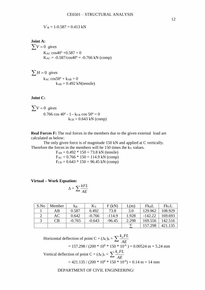
V’B = 1-0.587 = 0.413 kN
Joint A:
givesV 0
KAC cos40º +0.587 = 0
KAC = -0.587/cos40º = -0.766 kN (comp)
givesH 0
kAC cos50º + kAB = 0
kAB = 0.492 kN(tensile)
Joint C:
givesV 0
0.766 cos 40º - 1 - kCB cos 50º = 0
kCB = 0.643 kN (comp)
Real Forces F: The real forces in the members due to the given external load are
calculated as below:
The only given force is of magnitude 150 kN and applied at C vertically.
Therefore the forces in the members will be 150 times the kV values.
FAB = 0.492 * 150 = 73.8 kN (tensile)
FAC = 0.766 * 150 = 114.9 kN (comp)
FCB = 0.643 * 150 = 96.45 kN (comp)
Virtual – Work Equation:
∆ = AE
kFL
S.No Member kH KV F (kN) L(m) FkHL FkVL
1 AB 0.587 0.492 73.8 3.0 129.962 108.929
2 AC 0.642 -0.766 -114.9 1.928 -142.22 169.693
3 CB -0.765 -0.643 -96.45 2.298 169.556 142.516
∑ 157.298 421.135
Horizontal deflection of point C = (∆C)h = AE
FLkh
= 157.298 / (200 * 106 * 150 * 10-6 ) = 0.00524 m = 5.24 mm
Vertical deflection of point C = (∆C)v = AE
FLkv
= 421.135 / (200 * 106 * 150 * 10-6) = 0.14 m = 14 mm
CE6501 – STRUCTURAL ANALYSIS
13
DEPARTMENT OF CIVIL ENGINEERING/
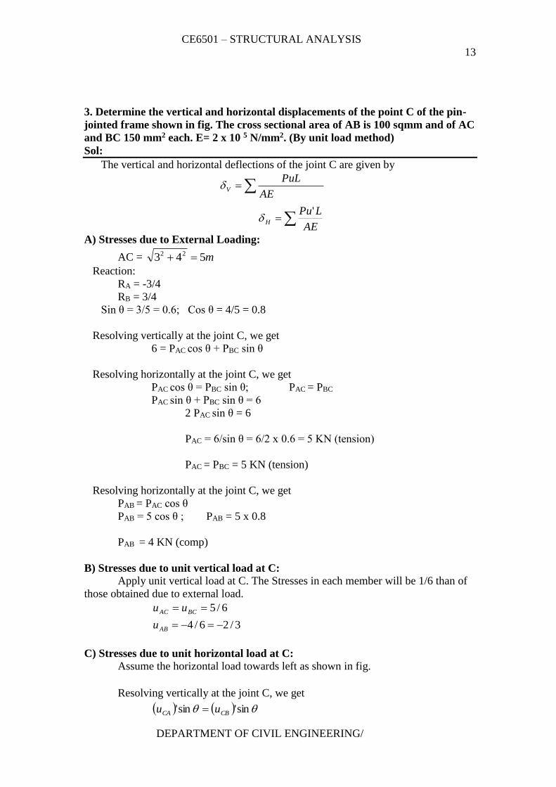
3. Determine the vertical and horizontal displacements of the point C of the pin-
jointed frame shown in fig. The cross sectional area of AB is 100 sqmm and of AC
and BC 150 mm2 each. E= 2 x 10 5 N/mm2. (By unit load method)
Sol:
The vertical and horizontal deflections of the joint C are given by
AE
LPu
AE
PuL
H
V
'
A) Stresses due to External Loading:
AC = m543 22
Reaction:
RA = -3/4
RB = 3/4
Sin θ = 3/5 = 0.6; Cos θ = 4/5 = 0.8
Resolving vertically at the joint C, we get
6 = PAC cos θ + PBC sin θ
Resolving horizontally at the joint C, we get
PAC cos θ = PBC sin θ; PAC = PBC
PAC sin θ + PBC sin θ = 6
2 PAC sin θ = 6
PAC = 6/sin θ = 6/2 x 0.6 = 5 KN (tension)
PAC = PBC = 5 KN (tension)
Resolving horizontally at the joint C, we get
PAB = PAC cos θ
PAB = 5 cos θ ; PAB = 5 x 0.8
PAB = 4 KN (comp)
B) Stresses due to unit vertical load at C:
Apply unit vertical load at C. The Stresses in each member will be 1/6 than of
those obtained due to external load.
3/26/4
6/5
AB
BCAC
u
uu
C) Stresses due to unit horizontal load at C:
Assume the horizontal load towards left as shown in fig.
Resolving vertically at the joint C, we get
sin'sin' CBCA uu
CE6501 – STRUCTURAL ANALYSIS
14
DEPARTMENT OF CIVIL ENGINEERING/
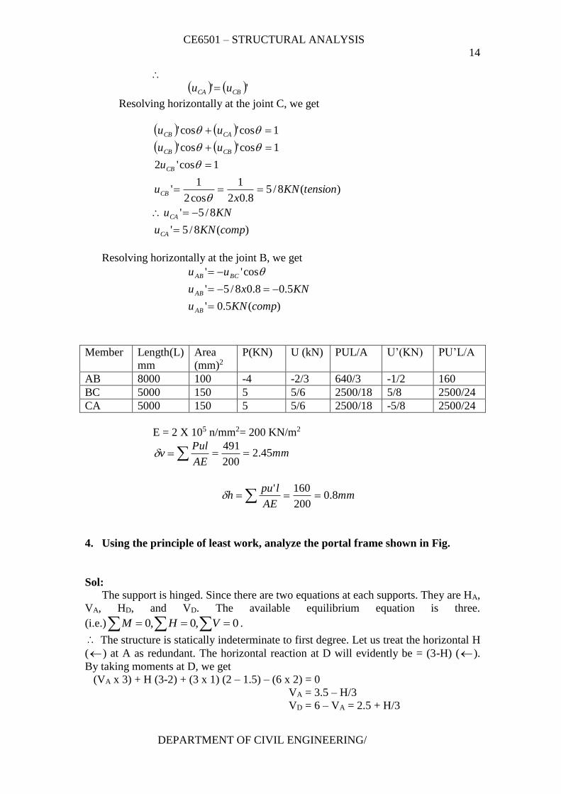
'' CBCA uu
Resolving horizontally at the joint C, we get
)(8/5'
8/5'
)(8/58.02
1
cos2
1'
1cos'2
1cos'cos'
1cos'cos'
compKNu
KNu
tensionKNx
u
u
uu
uu
CA
CA
CB
CB
CBCB
CACB
Resolving horizontally at the joint B, we get
)(5.0'
5.08.08/5'
cos''
compKNu
KNxu
uu
AB
AB
BCAB
Member Length(L)
mm
Area
(mm)2
P(KN) U (kN) PUL/A U’(KN) PU’L/A
AB 8000 100 -4 -2/3 640/3 -1/2 160
BC 5000 150 5 5/6 2500/18 5/8 2500/24
CA 5000 150 5 5/6 2500/18 -5/8 2500/24
E = 2 X 10⁵ n/mm2= 200 KN/m2
v mmAE
Pul45.2
200
491
mmAE
lpuh 8.0
200
160'
4. Using the principle of least work, analyze the portal frame shown in Fig.
Sol:
The support is hinged. Since there are two equations at each supports. They are HA,
VA, HD, and VD. The available equilibrium equation is three.
(i.e.) 0,0,0 VHM .
The structure is statically indeterminate to first degree. Let us treat the horizontal H
() at A as redundant. The horizontal reaction at D will evidently be = (3-H) ().
By taking moments at D, we get
(VA x 3) + H (3-2) + (3 x 1) (2 – 1.5) – (6 x 2) = 0
VA = 3.5 – H/3
VD = 6 – VA = 2.5 + H/3
CE6501 – STRUCTURAL ANALYSIS
15
DEPARTMENT OF CIVIL ENGINEERING/
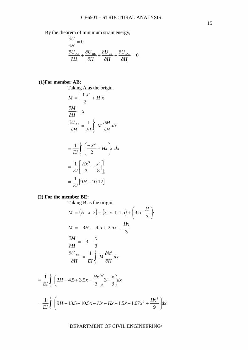
By the theorem of minimum strain energy,
0
0
H
U
H
U
H
U
H
U
H
U
DCCEBEAB
(1)For member AB: Taking A as the origin.
dxH
MM
EIH
U
xH
M
xHx
M
AB
3
0
2
1
.2
.1
12.1091
83
1
2
1
3
0
43
23
0
HEI
xHx
EI
dxxHxx
EI
(2) For the member BE:
Taking B as the origin.
dxH
MM
EIH
U
x
H
M
HxxHM
xH
xxHM
BE
1
0
1
33
35.35.43
35.35.1133
dxxHx
xHEI
3
33
5.35.431
1
0
dxHx
xxHxHxxHEI
9
67.15.15.105.1391 2
2
1
0
CE6501 – STRUCTURAL ANALYSIS
16
DEPARTMENT OF CIVIL ENGINEERING/
dxHx
xHxxHEI
9
67.12125.1391 2
2
1
0
1
0
3322
27389.065.139
1
HxxHxxxHx
EI
27389.065.139
1 2 HHH
EI
9.791
HEI
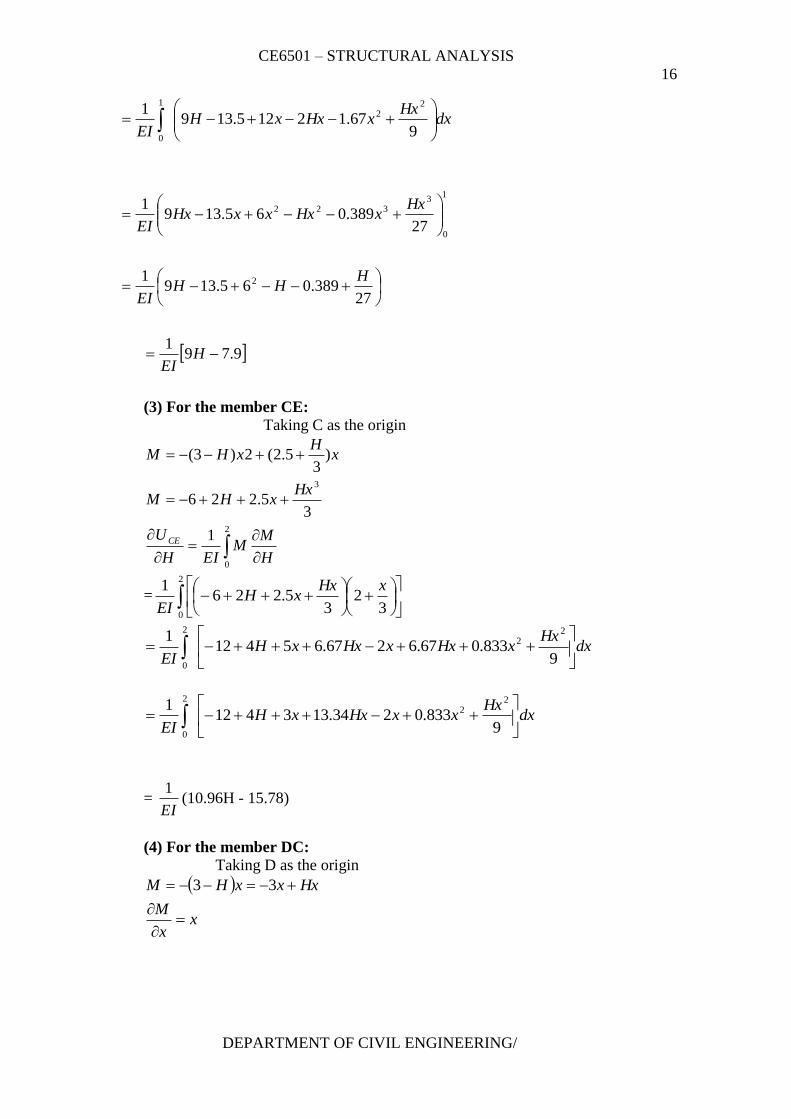
(3) For the member CE:
Taking C as the origin
2
0
3
1
35.226
)3
5.2(2)3(
H
MM
EIH
U
HxxHM
xH
xHM
CE
=
2
03
23
5.2261 xHx
xHEI
dxHx
xHxxHxxHEI
9
833.067.6267.654121 2
2
2
0
dxHx
xxHxxHEI
9
833.0234.1334121 2
2
2
0
= EI
1(10.96H - 15.78)
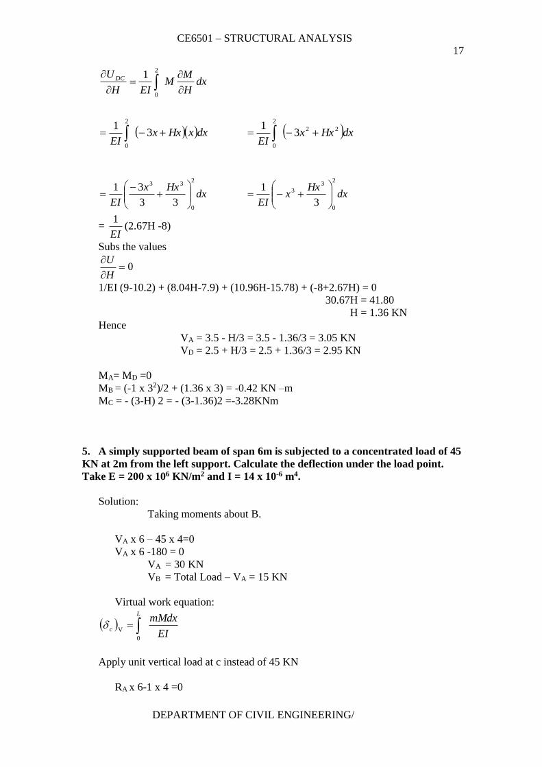
(4) For the member DC:
Taking D as the origin
xx
M
HxxxHM
33
CE6501 – STRUCTURAL ANALYSIS
17
DEPARTMENT OF CIVIL ENGINEERING/
dxH
MM
EIH
U DC
2
0
1
dxxHxxEI
31
2
0
dxHxxEI
22
2
0
31
dxHxx
EI
2
0
33
33
31
dx
Hxx
EI
2
0
33
3
1
= EI
1(2.67H -8)
Subs the values
0
H
U
1/EI (9-10.2) + (8.04H-7.9) + (10.96H-15.78) + (-8+2.67H) = 0
30.67H = 41.80
H = 1.36 KN
Hence
VA = 3.5 - H/3 = 3.5 - 1.36/3 = 3.05 KN
VD = 2.5 + H/3 = 2.5 + 1.36/3 = 2.95 KN
MA= MD =0
MB = (-1 x 32)/2 + (1.36 x 3) = -0.42 KN –m
MC = - (3-H) 2 = - (3-1.36)2 =-3.28KNm
5. A simply supported beam of span 6m is subjected to a concentrated load of 45
KN at 2m from the left support. Calculate the deflection under the load point.
Take E = 200 x 106 KN/m2 and I = 14 x 10-6 m4.
Solution:
Taking moments about B.
VA x 6 – 45 x 4=0
VA x 6 -180 = 0
VA = 30 KN
VB = Total Load – VA = 15 KN
Virtual work equation:
EI
mMdxL
c 0
V
Apply unit vertical load at c instead of 45 KN
RA x 6-1 x 4 =0
CE6501 – STRUCTURAL ANALYSIS
18
DEPARTMENT OF CIVIL ENGINEERING/
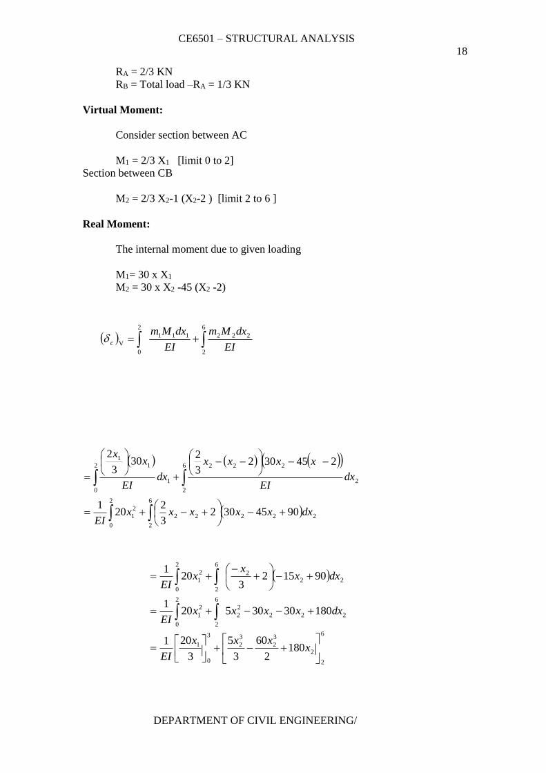
RA = 2/3 KN
RB = Total load –RA = 1/3 KN
Virtual Moment:
Consider section between AC
M1 = 2/3 X1 [limit 0 to 2]
Section between CB
M2 = 2/3 X2-1 (X2-2 ) [limit 2 to 6 ]
Real Moment:
The internal moment due to given loading
M1= 30 x X1
M2 = 30 x X2 -45 (X2 -2)
6
2
222111
2
0
VEI
dxMm
EI
dxMmc
2
0
6
2
22222
2
1
2
0
6
2
2
222
1
11
90453023
220
1
2453023
230
3
2
dxxxxxxEI
dxEI
xxxx
dxEI
xx
2
0
222
6
2
2
1 901523
201
dxxx
xEI
2
0
222
2
2
6
2
2
1 18030305201
dxxxxxEI
6
2
2
3
2
3
2
3
0
1 1802
60
3
5
3
201
x
xxx
EI
CE6501 – STRUCTURAL ANALYSIS
19
DEPARTMENT OF CIVIL ENGINEERING/
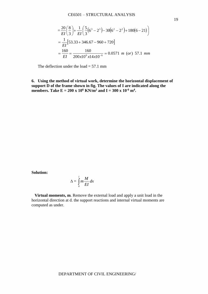
=
216180263026
3
51
3
820 2233
EIEI
mmormxxxEI
EI
1.57)(0571.0101410200
160160
72096067.34633.531
66
The deflection under the load = 57.1 mm
6. Using the method of virtual work, determine the horizontal displacement of
support D of the frame shown in fig. The values of I are indicated along the
members. Take E = 200 x 106 KN/m2 and I = 300 x 10-6 m4.
Solution:
∆ = l
dxEI
Mm
0
Virtual moments, m. Remove the external load and apply a unit load in the
horizontal direction at d. the support reactions and internal virtual moments are
computed as under.
CE6501 – STRUCTURAL ANALYSIS
20
DEPARTMENT OF CIVIL ENGINEERING/
(Sign for moments: Left clockwise +ve: Right clockwise +ve)
m1 = 1.x1 limits 0 to 2 m
m2 = 1.(2+x2 ) limits 0 to 2 m
m3 = 1.x3 limits 0 to 4 m
m4 = 1X4 limits 0 to 5 m
Real moments, M. Due to the given loading, the support reactions and real moments
are computed as under.
0H gives HA = 50 kN (←)
Taking moments about A,
VD x 5 – 50 x 2 = 0
VD = 50 x 2/5 = 20 kN (↑)
0V gives
VA = 20 kN (↓)
M 1 = 50 X x1
M 2 = 50 X (2 + x2) – 50 X x2 = 100 kNm
M 3 = 0
M 4 = 20 X x4
Virtual Work Equation:
(∆D)h = EI
mMdx
2
0
4
0
33
2
0
22111 0*)*1()100)(2(1)50)(.1(
EI
dxx
Ei
dxx
EI
dxxx
5
0
44 )*20)(4*1(
EI
dxx
CE6501 – STRUCTURAL ANALYSIS
21
DEPARTMENT OF CIVIL ENGINEERING/
=
5
0
2
4
2
0
2
22
2
0
3
1
2
40
2
100200
350
1 xxxx
EI
= 1/EI (1333.33 +600 +500) = 1233.33/EI
=1233.33/ 200*106 *300 *10-6 = 0.02056m = 20.56 mm
Horizontal displacement of support D, (∆D)h = 20.56 mm (→)
7. Using the method of virtual work, determine the horizontal displacement of
support D of the frame shown in fig. The values of I are indicated along the
members. Take E = 200 x 106 KN/m2 and I = 300 x 10-6 m4.
Solution:
∆ = l
EI
mMdx
0
Virtual moments, m. Remove the external load and apply unit horizontal load
at C. The support reactions and internal virtual moments are computed as shown.
0H gives HA= 1 kN (←)
Taking moments about C, VA *4 + 1* 5 = 0
4VA = -5
VA = -5/4 = - 12.5 i.e. VA = 1.25 kN (↓)
0V gives
VC = 1.25 kN (↑)
M1 = 1.x1 (x1 varies from 0 to 2.5 m)
M2 = 1.x2 (x2 varies from 2.5 to 5.0 m)
M3 = 1.25x3(x3 varies from 0 to 4 m)
Real moments. Due to the given external loading, the support react ions and
real moments are computed as shown below.
0H gives HA= 30 kN (←)
Taking moments about A, RA *4 - 10* 4 * 4/2 – 30 * 2.5 = 0
4RC = 80+75 = 155
CE6501 – STRUCTURAL ANALYSIS
22
DEPARTMENT OF CIVIL ENGINEERING/
RC = 38.75 kN
RA = Total load – RC = 10*4 – 38.75 = 1.25 kN
M1 = = 30*x1 (x1 varies from 0 to 2.5)
M2 = 30x2 – 30(x2 – 2.5) (x2 varies from 2.5 to 5)
Virtual Work Equation:
(∆C)h = EI
mMdx
5.2
0
2222111 )5.2(3030).1()30)(.1(
dxEI
xxx
EI
dxxx
4
0
3
2
333 )575.38)(25.1(
EI
dxxxx
=
4
0
4
3
3
3
0.5
5.2
2
2
5.2
0
3
1
425.6
344.48
1
2
75
3
30
xx
EI
x
EI
x
EI
=
4322 4
4
25.64
3
44.485.25
2
7526.156
1xx
EI
(∆C)h = mmm 108108.010*4*10*2
512.8668
Horizontal displacement of point C = 108 mm
UNIT – II
MOVING LOADS AND INFLUENCE LINES
(Determinate and Indeterminate structures)
Influence lines for reactions in statically determinate structures – influence
lines for members forces in pin-jointed frames – Influence lines for shear force
and bending moment in beam sections – Calculation of critical stress resultants
due to concentrated and distributed moving loads. Muller Breslaur’s principle –
Influence lines for continuous beams and single storey rigid frames – Indirect
model analysis for influence lines of indeterminate structures – Beggs deformeter.
S.NO 2 MARKS PAGE NO
1 What is meant by influence lines? 4
CE6501 – STRUCTURAL ANALYSIS
23
DEPARTMENT OF CIVIL ENGINEERING/
2 Draw the influence line diagram for shear force at a point X in a
Simply supported beam AB of span ‘l’ m. 4
3 Draw the ILD for bending moment at any section X of a simply
supported beam and mark the ordinates 4
4 What are the uses of influence line diagram? 4
5 Sketch the ILDs for the support reactions in a simply supported
beam. 4
6 A simply supported beam of span 10m carries a udl of 20 kN/m
over its central 4m length. With the help of influence line
diagram, find the shear force at 3m from the left support.
4
7 Sketch the influence line for shear force at a section D in the
cantilever shown in fig. 5
8 Draw the influence line diagram for shear force at C and hence
determine shear force at C for the given loading.(April/may 04) 5
9 State Muller – Bresalu principle. 6
10 Using Muller – Bresalu principle, construct the influence line
diagram for RB in the continuous beam shown in fig. 6
11 Sketch the influence line diagram for horizontal reaction at the
left support of a single bay single storey portal with fixed legs. 6
12 Sketch the influence line for reaction at B in the overhanging
beam shown in fig.(April/May 05) 7
13 For the two member determine bent in fig. sketch the influence
line for VA. 7
14 State the principle on which indirect model analysis is based?
(Nov/Dec 05) 7
15 What is Begg’s deformeter? 7
16 What is ‘dummy length’ in models tested with Begg’s
deformeter. 8
17 What are three types of connections possible with the model
used with Begg’s deformeter. 9
18 What is the use of a micrometer microscope in model analysis
with Begg’s deformeter?
19 Sketch the plugs used for including axial displacements in the
model analysis using Begg’s deformeter.
20 Sketch the shear plugs and moment plugs used in Begg’s
deformeter.
21 Name the types of rolling loads for which the absolute maximum
bending moment occurs at the mid span of a beam.
22 What is meant by absolute maximum bending moment in a
beam?
23 The portal frame in fig. is hinged at D and is on rollers at A.
Sketch the influence line for bending moment at B.
CE6501 – STRUCTURAL ANALYSIS
24
DEPARTMENT OF CIVIL ENGINEERING/
S.NO 16 MARKS PAGE NO
1
A single rolling load of 100 kN moves on a girder of span 20m.
(a) Construct the influence lines for (i) shear force and (ii)
bending moment for a section 5m from the left support. (b)
Construct the influence lines for points at which the maximum
shears and maximum bending moment develop. Determine these
values.
11
2
Draw the ILD for shear force and bending moment for a section
at 5m from the left hand support of a simply supported beam,
20m long. Hence, calculate the maximum bending moment and
shear force at the section, due to a uniformly distributed rolling
load of length 8m and intensity 10 kN/m run.(Apr/May 05)
15
3
Two point loads of 100 kN and 200 kN spaced 3m apart cross a
girder of span 15m from left to right with the 100 kN load
loading. Draw the influence line for shear force and bending
moment and find the value of maximum shear force and bending
moment at a section, 6m from the left hand support. Also, find
the absolute maximum moment due to the given load system
18
4
A train of 5 wheel loads crosses a simply supported beam of
span 22.5 m. Using influence lines, calculate the maximum
positive and negative shear forces at mid span and absolute
maximum bending moment anywhere in the span.(Nov/Dec 05)
20
5
A girder a span of 18mis simply supported at the ends. It is
traversed by a train of loads as shown in fig. The 50 kN load
loading. Find the maximum bending moment which can occur (i)
under the 200 kN load (ii) Under 50 kN load, using influence
line diagrams.
23
6 Draw the I.L for reaction at B and for the support moment MA at
A for the propped cantilever in fig. Compute the I.L ordinates at
1.5 m intervals.
24
7
In a simply supported girder AB of span 2om, determine the
maximum bending moment and maximum shear force at a
section 5m from A, due to the passage of a uniformly distributed
load of intensity 20 kN/m, longer than the span.
2 6
UNIT – II
TWO MARKS QUESTIONS AND ANSWERS
1. What is meant by influence lines?
An influence line is a graph showing, for any given beam frame or
truss, the variation of any force or displacement quantity (such as shear force,
bending moment, tension, deflection) for all positions of a moving unit load as it
crosses the structure from one end to the other.
2. Draw the influence line diagram for shear force at a point X in a
Simply supported beam AB of span ‘l’ m.
CE6501 – STRUCTURAL ANALYSIS
25
DEPARTMENT OF CIVIL ENGINEERING/
3. Draw the ILD for bending moment at any section X of a simply
supported beam and mark the ordinates.
4. What are the uses of influence line diagram?
(i) Influence lines are very useful in the quick determination of
reactions, shear force, bending moment or similar functions at a
given section under any given system of moving loads and
(ii) Influence lines are useful in determining the load position to cause
maximum value of a given function in a structure on which load
positions can vary.
5. Sketch the ILDs for the support reactions in a simply supported beam.
CE6501 – STRUCTURAL ANALYSIS
26
DEPARTMENT OF CIVIL ENGINEERING/
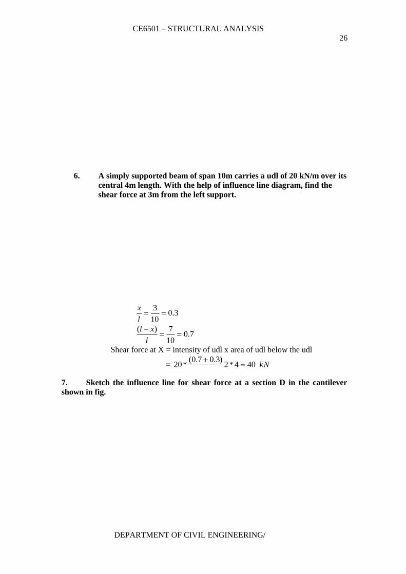
6. A simply supported beam of span 10m carries a udl of 20 kN/m over its
central 4m length. With the help of influence line diagram, find the
shear force at 3m from the left support.
3.010
3
l
x
7.010
7)(
l
xl
Shear force at X = intensity of udl x area of udl below the udl
= kN404*2)3.07.0(
*20
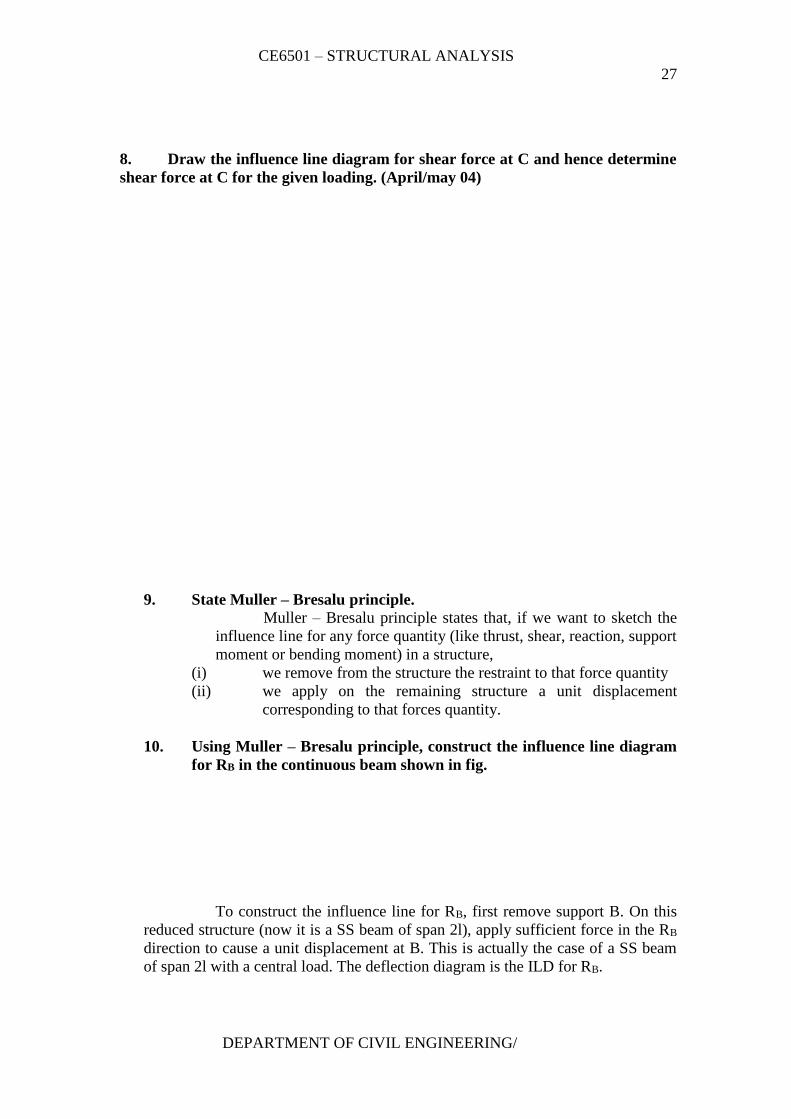
7. Sketch the influence line for shear force at a section D in the cantilever
shown in fig.
CE6501 – STRUCTURAL ANALYSIS
27
DEPARTMENT OF CIVIL ENGINEERING/
8. Draw the influence line diagram for shear force at C and hence determine
shear force at C for the given loading. (April/may 04)
9. State Muller – Bresalu principle.
Muller – Bresalu principle states that, if we want to sketch the
influence line for any force quantity (like thrust, shear, reaction, support
moment or bending moment) in a structure,
(i) we remove from the structure the restraint to that force quantity
(ii) we apply on the remaining structure a unit displacement
corresponding to that forces quantity.
10. Using Muller – Bresalu principle, construct the influence line diagram
for RB in the continuous beam shown in fig.
To construct the influence line for RB, first remove support B. On this
reduced structure (now it is a SS beam of span 2l), apply sufficient force in the RB
direction to cause a unit displacement at B. This is actually the case of a SS beam
of span 2l with a central load. The deflection diagram is the ILD for RB.
CE6501 – STRUCTURAL ANALYSIS
28
DEPARTMENT OF CIVIL ENGINEERING/
11. Sketch the influence line diagram for horizontal reaction at the left
support of a single bay single storey portal with fixed legs.
To draw the influence line diagram for HA, place support A on
rollers so that horizontal displacement at A is permitted. Apply a unit
horizontal displacement at A. The resulting displaced shapes are the
ILD for HA.
12. Sketch the influence line for reaction at B in the overhanging beam
shown in fig.(April/May 05)
CE6501 – STRUCTURAL ANALYSIS
29
DEPARTMENT OF CIVIL ENGINEERING/
13. For the two member determine bent in fig. sketch the influence line for
VA.
If we deftly apply Muller – Breslau to the problem, we can first remove
support A and push A up by unit distance. Since the angle at B will remain
unchanged, our unit displacement will result in a rigid body rotation of θ (=1/4
radian) about C. So the column CB will also have a horizontal displacement. (For
the part AB, the diagram is just the influence line diagram for shear in a S.S beam)
The diagram for BC must be understood to be the influence of horizontal loads
on the column on RA.
14. State the principle on which indirect model analysis is based?
(Nov/Dec 05)
The indirect model analysis is based on the Muller Bresalu principle.
Muller Breslau principle has lead to simple method of using
models of structures to get the influence lines for force quantities like bending
moments, support moments, reactions, internal shears, thrusts, etc.
To get the influence line for any force quantity (i) remove the
restraint due to the force, (ii) apply a unit displacement in the direction of the force.
15. What is Begg’s deformeter?
Begg’s deformeter is a device to carry out indirect model analysis on
structures. It has the facility to apply displacement corresponding to moment,
shear or thrust at any desired point in the model. In addition, it provides facility
to measure accurately the consequent displacements all over the model.
16. What is ‘dummy length’ in models tested with Begg’s deformeter.
Dummy length is the additional length (of about 10 to 12 mm)
left at the extremities of the model to enable any desired connection to be made
with the gauges.
17. What are three types of connections possible with the model used with
Begg’s deformeter.
(i) Hinged connection
CE6501 – STRUCTURAL ANALYSIS
30
DEPARTMENT OF CIVIL ENGINEERING/
(ii) Fixed connection
(iii) Floating connection
18. What is the use of a micrometer microscope in model analysis with
Begg’s deformeter?
Micrometer microscope is an instrument used to measure the displacements
of any point in the x and y directions of a model during tests with Begg’s
deformeter.
19. Sketch the plugs used for including axial displacements in the model
analysis using Begg’s deformeter.
20. Sketch the shear plugs and moment plugs used in Begg’s deformeter.
21. Name the types of rolling loads for which the absolute maximum
bending moment occurs at the mid span of a beam.
Types of rolling loads:
(i) Single concentrated load
(ii) Udl longer than the span
(iii) Udl shorter than the span
22. What is meant by absolute maximum bending moment in a beam?
When a given load system moves from one end to the other end of a
girder, depending upon the position of the load, there will be a maximum
bending moment for every section. The maximum of these maximum
bending moments will usually occur near or at the mid span. This
maximum of maximum bending moment is called the absolute maximum
bending moment, Mmaxmax.
23. The portal frame in fig. is hinged at D and is on rollers at A. Sketch the
influence line for bending moment at B.
CE6501 – STRUCTURAL ANALYSIS
31
DEPARTMENT OF CIVIL ENGINEERING/
To get the influence line diagram for MB, we shall introduce a
hinge at B (and remove the resistance to bending moment). Now we get a unit
rotation between BA and BC at B.
BC cannot rotate since column CD will prevent the rotation. BA
would rotate freely (with zero moment). For θ =1 at B, displacement at A = 3m.
The displaced position shows the influence line for MB as shown in fig.
SIXTEEN MARKS QUESTIONS AND ANSWERS
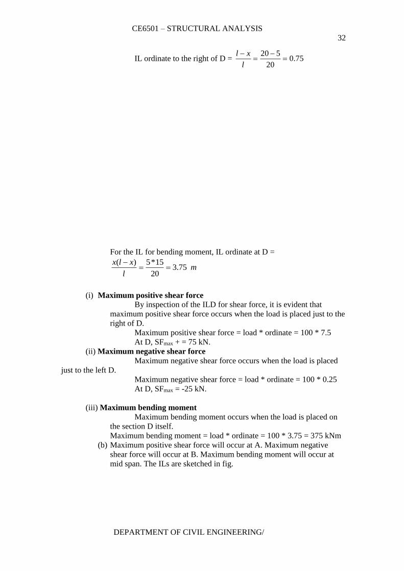
1. A single rolling load of 100 kN moves on a girder of span 20m. (a)
Construct the influence lines for (i) shear force and (ii) bending
moment for a section 5m from the left support. (b) Construct the
influence lines for points at which the maximum shears and maximum
bending moment develop. Determine these values.
Solution:
(a) To find maximum shear force and bending moment at 5m from the left
support:
For the ILD for shear,
CE6501 – STRUCTURAL ANALYSIS
32
DEPARTMENT OF CIVIL ENGINEERING/
IL ordinate to the right of D = 75.020
520
l
xl
For the IL for bending moment, IL ordinate at D =
ml
xlx75.3
20
15*5)(
(i) Maximum positive shear force
By inspection of the ILD for shear force, it is evident that
maximum positive shear force occurs when the load is placed just to the
right of D.
Maximum positive shear force = load * ordinate = 100 * 7.5
At D, SFmax + = 75 kN.
(ii) Maximum negative shear force
Maximum negative shear force occurs when the load is placed
just to the left D.
Maximum negative shear force = load * ordinate = 100 * 0.25
At D, SFmax = -25 kN.
(iii) Maximum bending moment
Maximum bending moment occurs when the load is placed on
the section D itself.
Maximum bending moment = load * ordinate = 100 * 3.75 = 375 kNm
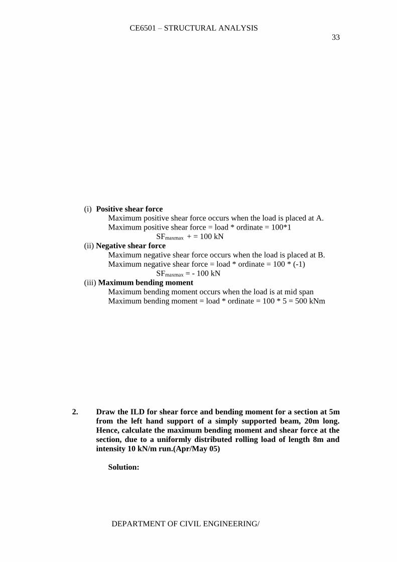
(b) Maximum positive shear force will occur at A. Maximum negative
shear force will occur at B. Maximum bending moment will occur at
mid span. The ILs are sketched in fig.
CE6501 – STRUCTURAL ANALYSIS
33
DEPARTMENT OF CIVIL ENGINEERING/
(i) Positive shear force
Maximum positive shear force occurs when the load is placed at A.
Maximum positive shear force = load * ordinate = 100*1
SFmaxmax + = 100 kN
(ii) Negative shear force
Maximum negative shear force occurs when the load is placed at B.
Maximum negative shear force = load * ordinate = 100 * (-1)
SFmaxmax = - 100 kN
(iii) Maximum bending moment
Maximum bending moment occurs when the load is at mid span
Maximum bending moment = load * ordinate = 100 * 5 = 500 kNm
2. Draw the ILD for shear force and bending moment for a section at 5m
from the left hand support of a simply supported beam, 20m long.
Hence, calculate the maximum bending moment and shear force at the
section, due to a uniformly distributed rolling load of length 8m and
intensity 10 kN/m run.(Apr/May 05)
Solution:
CE6501 – STRUCTURAL ANALYSIS
34
DEPARTMENT OF CIVIL ENGINEERING/
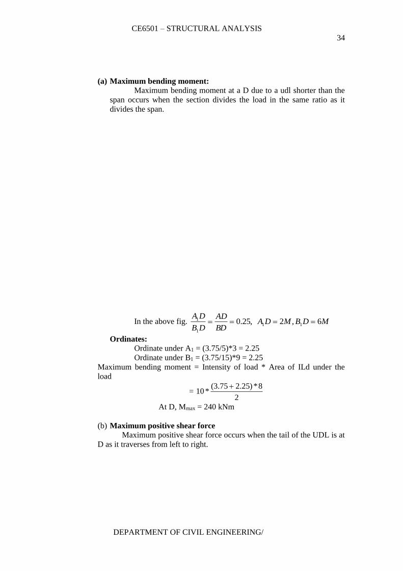
(a) Maximum bending moment:
Maximum bending moment at a D due to a udl shorter than the
span occurs when the section divides the load in the same ratio as it
divides the span.
In the above fig. MDBMDABD
AD
DB
DA6,2,25.0 11
1
1
Ordinates:
Ordinate under A1 = (3.75/5)*3 = 2.25
Ordinate under B1 = (3.75/15)*9 = 2.25
Maximum bending moment = Intensity of load * Area of ILd under the
load
= 2
8*)25.275.3(*10
At D, Mmax = 240 kNm
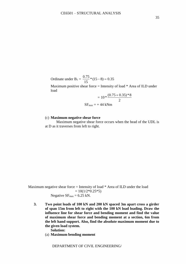
(b) Maximum positive shear force Maximum positive shear force occurs when the tail of the UDL is at
D as it traverses from left to right.
CE6501 – STRUCTURAL ANALYSIS
35
DEPARTMENT OF CIVIL ENGINEERING/
Ordinate under B1 = 35.0)815(*15
75.0
Maximum positive shear force = Intensity of load * Area of ILD under
load
= 2
8*)35.075.0(*10
SFmax = + 44 kNm
(c) Maximum negative shear force Maximum negative shear force occurs when the head of the UDL is
at D as it traverses from left to right.
Maximum negative shear force = Intensity of load * Area of ILD under the load
= 10(1/2*0.25*5)
Negative SFmax = 6.25 kN.
3. Two point loads of 100 kN and 200 kN spaced 3m apart cross a girder
of span 15m from left to right with the 100 kN load loading. Draw the
influence line for shear force and bending moment and find the value
of maximum shear force and bending moment at a section, 6m from
the left hand support. Also, find the absolute maximum moment due to
the given load system.
Solution:
(a) Maximum bending moment
CE6501 – STRUCTURAL ANALYSIS
36
DEPARTMENT OF CIVIL ENGINEERING/
Max. Ordinate of ILD = ml
xlx6.3
15
9*6)(
Maximum bending moment at D occurs under the critical load. This
load, when it moves from left to right of ‘D’ changes the sign of Lr, the differential
loading rate, where,
xl
W
x
WL
rightleft
r
Now, let us try with 200 kN load. Firstly, keep this 200 kN load to the left of
‘D’.
xl
W
x
WL
rightleft
r
= )(22.229
100
6
200ve
Moving this load to the right of ‘D’,
xl
W
x
WL
rightleft
r
= )(33.339
300
6
0ve
Since, the sign of Lr changes, the 200 kN load is critical. The maximum
bending moment occurs at D when this 200 kN load is placed at D.
CE6501 – STRUCTURAL ANALYSIS
37
DEPARTMENT OF CIVIL ENGINEERING/
Ordinate under 100 kN load = 4.26*9
6.3
Maximum bending moment =
4.2*1006.3*200)*( ordinateload
(b) Maximum shear force:
(i) Positive shear force
Fig. shows the load position for the absolute maximum positive shera
force. If the load train is moved to the left, the positive contribution due to the bigger
(160 kN) load is lost and a negative contribution is obtained.
If the load train moves to the right, the ordinates under to the loads
decrease. Hence, the indicated load position is the critical one.
Ordinate under 200 kN load = 0.6
Ordinate under 100 kN load = 4.09
6.0
Maximum positive shear force = 200 (0.6) + 100 (0.4)
SFmax = + 160 kN.
(ii) Negative shear force
CE6501 – STRUCTURAL ANALYSIS
38
DEPARTMENT OF CIVIL ENGINEERING/
Trying with 100 kN load, first keep this 100 kN load to the left of D. Then move this
load to the right of ‘D’ by 3m. If the value of the shear increment Si is a negative value,
it includes a decrease in negative shear force.
)(4010015
3*3001 veW
l
WS c
i
Hence, the negative shear force decreases when this load train is moved to the
right of ‘D’. Hence, to get maximum shear force, this 100 kN load should be kept just
to the left of D.
Ordinate under 100 kN load = 0.4
Ordinate under 200 kN load = 2.03*6
4.0
Maximum negative shear force = 100*0.4 + 200*0.2 = 80
SFmax = - 80 kN
(c) Absolute maximum bending moment
(i) Resultant of the loads
Taking moments about 200 kN load,
100*3 = R.x, R = 300 kN. X = 1.0 m
Absolute maximum bending moment occurs under the load
which is nearer to the resultant ‘R’. The critical position is when the
resultant ‘R’ and the load are at equal distance from the centre of span
© .
Distance of this 200 kN from C = Distance of ‘R’ from c.
Maximum ordinate of ILD (i.e) ordinate under 200 kN load = ml
xlx733.3
)(
Ordinate under 100 kN load = (3.733*6)/9 =2.489 m
Absolute maximum bending moment, Mmaxmax = )tan*( ceDisload
= 200 * 3.733 + 100*2.489 = 995.5 kNm
CE6501 – STRUCTURAL ANALYSIS
39
DEPARTMENT OF CIVIL ENGINEERING/
4. A train of 5 wheel loads crosses a simply supported beam of span 22.5
m. Using influence lines, calculate the maximum positive and negative
shear forces at mid span and absolute maximum bending moment
anywhere in the span.(Nov/Dec 05)
Solution:
(a) Maximum shear force
(i) Positive shear force
To determine the load position to get the maximum positive shear force, let us
keep all the loads to the right of C. Then move W1 load to the left of ‘C’ by 2.5 m.
if the sign of shear increments Si is negative, it will indicate that W1 shall be
retained at C.
1Wl
WS c
i
W = Total load on the span = 120 + 160 +400 + 260 +240 = 1182 kN.
C = Distance through which the load train is moved = 2.5 m
CE6501 – STRUCTURAL ANALYSIS
40
DEPARTMENT OF CIVIL ENGINEERING/
)(11.111205.22
5.2*1180veS i
Since Si is positive, the shear force increases due to thr shifting of W1 to the left
of C. Again, let us move W2 to the left of C by 2.5 m to check whether the shera
force further increases or not.
)(89.281605.22
5.2*11802 veW
l
WS c
i
Since Si is negative, it undicates that to get maximum positive shear force, W2
should stay just right of C.
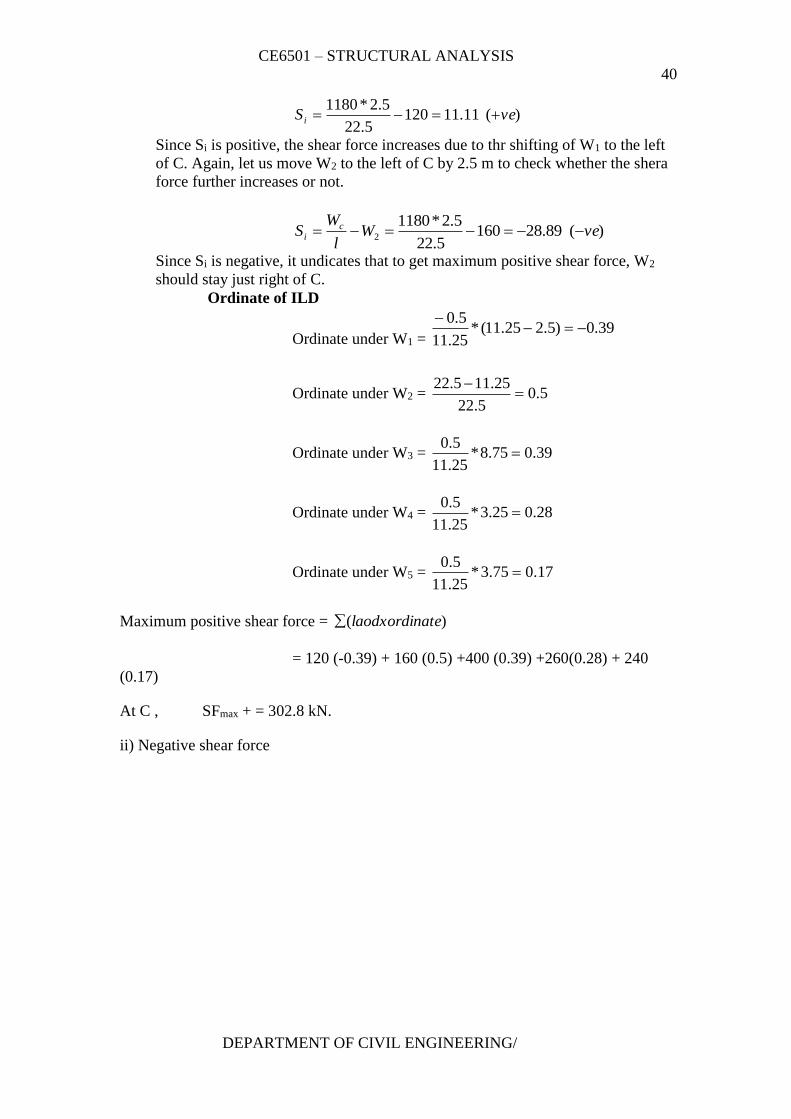
Ordinate of ILD
Ordinate under W1 = 39.0)5.225.11(*
25.11
5.0
Ordinate under W2 = 5.05.22
25.115.22
Ordinate under W3 = 39.075.8*25.11
5.0
Ordinate under W4 = 28.025.3*25.11
5.0
Ordinate under W5 = 17.075.3*25.11
5.0
Maximum positive shear force = )( atelaodxordin
= 120 (-0.39) + 160 (0.5) +400 (0.39) +260(0.28) + 240
(0.17)
At C , SFmax + = 302.8 kN.
ii) Negative shear force
CE6501 – STRUCTURAL ANALYSIS
41
DEPARTMENT OF CIVIL ENGINEERING/
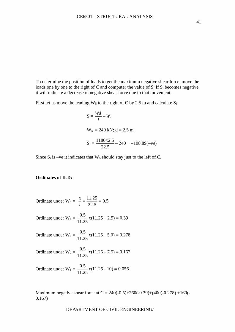
To determine the position of loads to get the maximum negative shear force, move the
loads one by one to the right of C and computer the value of Si.If Si becomes negative
it will indicate a decrease in negative shear force due to that movement.
First let us move the leading W5 to the right of C by 2.5 m and calculate Si
Si= 5Wl
Wd
W5 = 240 kN; d = 2.5 m
Si = )(89.1082405.22
5.21180ve
x
Since Si is –ve it indicates that W5 should stay just to the left of C.
Ordinates of ILD:
Ordinate under W5 = 5.05.22
25.11
l
x
Ordinate under W4 = 39.0)5.225.11(25.11
5.0x
Ordinate under W3 = 278.0)0.525.11(25.11
5.0x
Ordinate under W2 = 167.0)5.725.11(25.11
5.0x
Ordinate under W1 = 056.0)1025.11(25.11
5.0x
Maximum negative shear force at C = 240(-0.5)+260(-0.39)+(400(-0.278) +160(-
0.167)

CE6501 – STRUCTURAL ANALYSIS
42
DEPARTMENT OF CIVIL ENGINEERING/
+120(-0.056)
Fmax = 366.04 kN.
b) Absolute maximum bending moment
i) Position of resultant of all loads
Taking moments about W1, 120(0)+160(2.5)+400(5.0)+260(7.5)+240(10.0) =R.
x
R = 1180kN
x = 5,72m from W1
ii) Location of absolute maximum bending moment
Absolute maximum bending moment occurs under the load, which is nearest to the
resultant ‘R’.(In this problem W3 is nearest to the resultant ‘R’).The distance between
C and R and the distance between C and W3 shall be equal.
Distance between R and center of span(C) = ½ (0.72) =0.36 m
In this fig. Shows the IL for bending moment at the critical spot D, 10.89 m fro A.
Ordinates of ILD:
CE6501 – STRUCTURAL ANALYSIS
43
DEPARTMENT OF CIVIL ENGINEERING/
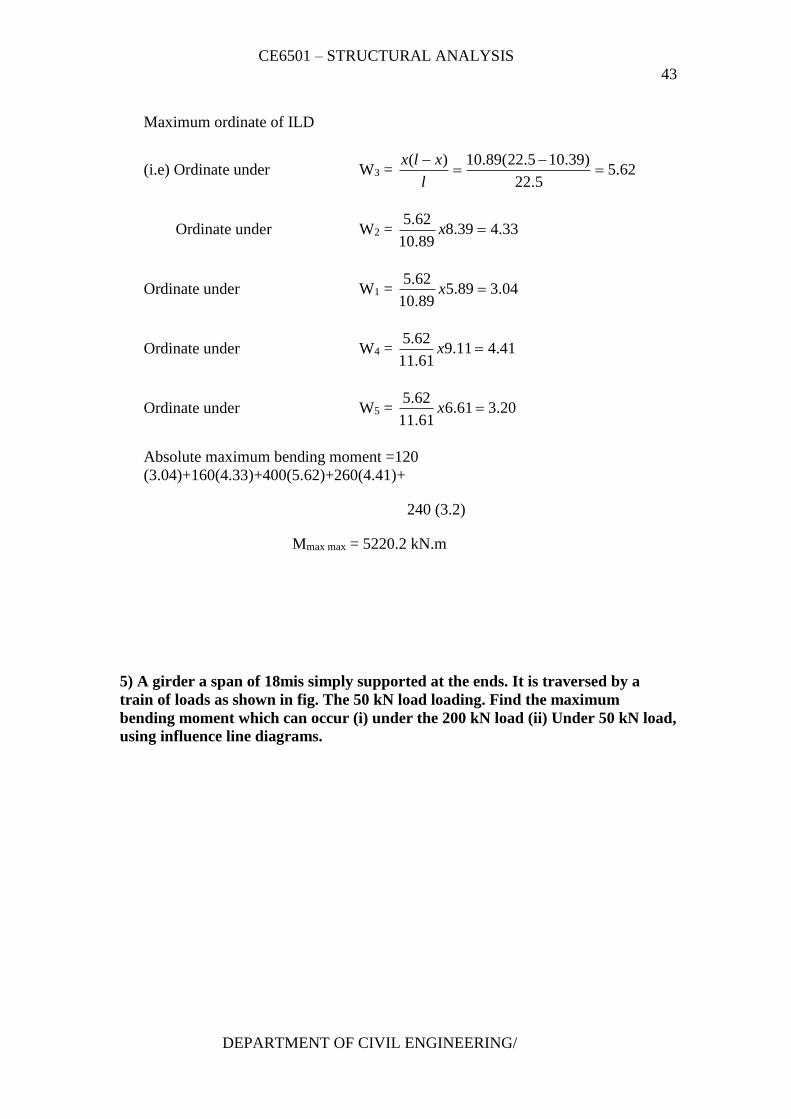
Maximum ordinate of ILD
(i.e) Ordinate under W3 = 62.55.22
)39.105.22(89.10)(
l
xlx
Ordinate under W2 = 33.439.889.10
62.5x
Ordinate under W1 = 04.389.589.10
62.5x
Ordinate under W4 = 41.411.961.11
62.5x
Ordinate under W5 = 20.361.661.11
62.5x
Absolute maximum bending moment =120
(3.04)+160(4.33)+400(5.62)+260(4.41)+
240 (3.2)
Mmax max = 5220.2 kN.m
5) A girder a span of 18mis simply supported at the ends. It is traversed by a
train of loads as shown in fig. The 50 kN load loading. Find the maximum
bending moment which can occur (i) under the 200 kN load (ii) Under 50 kN load,
using influence line diagrams.
CE6501 – STRUCTURAL ANALYSIS
44
DEPARTMENT OF CIVIL ENGINEERING/
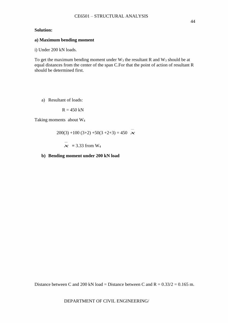
Solution:
a) Maximum bending moment
i) Under 200 kN loads.
To get the maximum bending moment under W3 the resultant R and W3 should be at
equal distances from the center of the span C.For that the point of action of resultant R
should be determined first.
a) Resultant of loads:
R = 450 kN
Taking moments about W4
200(3) +100 (3+2) +50(3 +2+3) = 450
x
x = 3.33 from W4
b) Bending moment under 200 kN load
Distance between C and 200 kN load = Distance between C and R = 0.33/2 = 0.165 m.
CE6501 – STRUCTURAL ANALYSIS
45
DEPARTMENT OF CIVIL ENGINEERING/
Ordiantes of ILD :
ILD under W3 = l
xlx )(
X= 8.335m
l-x = 18-8.835 = 9.165 m
ILD under W3 = m50.418
1365.9*835.8
ILD under W4 = m97.2835.8
835.5*5.4
ILD under W2 = m52.3165.9
)165.43(*5.4
ILD under W1 = m05.2165.9
165.4*5.4
Bending moment under the 200 kN load
= 200 (4.5) + 100 (2.97) + 100 (3.52) +50 (2.05) = 1651.5 kNm.
(ii) Bending moment under the load 50 kN load
To get the maximum bending moment under W1 , W2 and R must be at
equal distances from the centre of span ©. Distance between C and R = Distance
between C and W1 = ½ (2 – 0.33 + 3) = ½ (4.67) = 2.335 m
Ordinates of ILD:
CE6501 – STRUCTURAL ANALYSIS
46
DEPARTMENT OF CIVIL ENGINEERING/
ILD under W1 = ml
xlx20.4
18
665.6*335.11)(
ILD under W2 = ml
xlx09.3
335.11
335.8*2.4)(
ILD under W3 = ml
xlx35.2
335.11
335.6*2.4)(
ILD under W4 = ml
xlx24.1
335.11
335.3*2.4)(
Bending moment under the load 50 kN load
= 4.2 (50) + 3.09 (100) +2.35 (200) +1.24 (100) = 1113 kN
m.
6.Draw the I.L for reaction at B and for the support moment MA at A for the
propped cantilever in fig. Compute the I.L ordinates at 1.5 m intervals.
Solution:
Remove the restraint due to RB (remove support B)
Apply a unit displacement (upward).
When RB = 1, then YXB is the displacement at section x due
to unit load applied at B.
Mx = -EI xdx
dEIxxR
dx
yd y
B 2
2
2
2
:.1.
CE6501 – STRUCTURAL ANALYSIS
47
DEPARTMENT OF CIVIL ENGINEERING/
11
3
1
2
6
2
CxCx
EIy
Cx
dx
dyEI
At x= 12, y = 0, dy/dx = 0
Hence , C1 = 72, C2 = -576
YXB =
57672
6
1 2
xx
EI
YBB (at x = 0 ) = EI
576
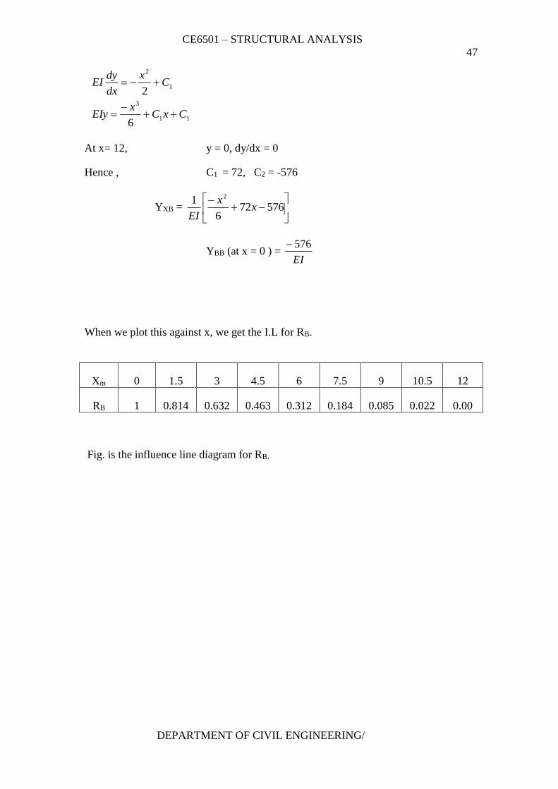
When we plot this against x, we get the I.L for RB.
Xm 0 1.5 3 4.5 6 7.5 9 10.5 12
RB 1 0.814 0.632 0.463 0.312 0.184 0.085 0.022 0.00
Fig. is the influence line diagram for RB.
CE6501 – STRUCTURAL ANALYSIS
48
DEPARTMENT OF CIVIL ENGINEERING/
To get the I.L for MA have to
(i) Introduce a hinge at A and
(ii) We have to apply a unit rotation at A. Instead we will apply a unit moment at
A find the general displacement at any x from B. We will then divide the
displacement by the actual rotation at A.
Due to
1
2
2
2
24
12
12/1
1
Cx
dx
dyEi
x
dx
ydEIM
RR
M
x
AB
A
CE6501 – STRUCTURAL ANALYSIS
49
DEPARTMENT OF CIVIL ENGINEERING/
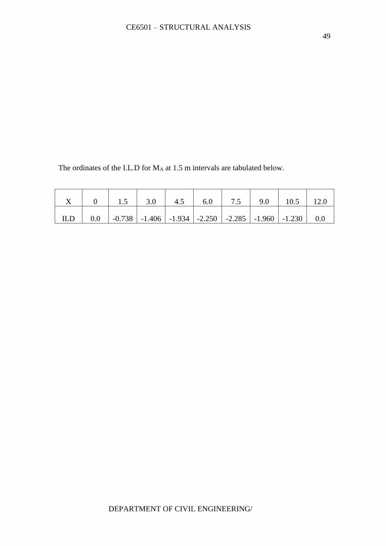
The ordinates of the I.L.D for MA at 1.5 m intervals are tabulated below.
X 0 1.5 3.0 4.5 6.0 7.5 9.0 10.5 12.0
ILD 0.0 -0.738 -1.406 -1.934 -2.250 -2.285 -1.960 -1.230 0.0
CE6501 – STRUCTURAL ANALYSIS
50
DEPARTMENT OF CIVIL ENGINEERING/
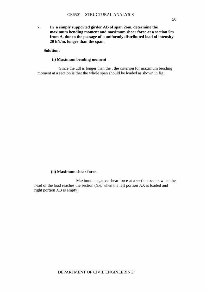
7. In a simply supported girder AB of span 2om, determine the
maximum bending moment and maximum shear force at a section 5m
from A, due to the passage of a uniformly distributed load of intensity
20 kN/m, longer than the span.
Solution:
(i) Maximum bending moment
Since the udl is longer than the , the criterion for maximum bending
moment at a section is that the whole span should be loaded as shown in fig.
(ii) Maximum shear force
Maximum negative shear force at a section occurs when the
head of the load reaches the section ((i.e. when the left portion AX is loaded and
right portion XB is empty)
CE6501 – STRUCTURAL ANALYSIS
51
DEPARTMENT OF CIVIL ENGINEERING/
(iii) Maximum positive shear force:
Maximum positive shear force occurs at X when the tail of
the load is at X as it moves from left to right. (i.e. AX is empty and the portion XB is
loaded)
Maximum positive shear force = RA
UNIT – III
ARCHES
Arches as structural forms – Examples of arch structures – Types of
arches – Analysis of Three hinged, two hinged and fixed arches, parabolic and
Circular arches – Settlement and temperature effects.
S.NO 2 MARKS PAGE NO
1 What is an arch? Explain. 4
2 What is a linear arch? 4
3 State Eddy’s theorem. 4
4 What is the degree of static indeterminacy of a three-hinged
parabolic arch? 5
5
A three hinged parabolic arch hinged at the crown and springings
has a horizontal span of 12m and a central rise of 2.5m. it carries
a udl of 30 kN/m run over the left hand half of the span.
Calculate the resultant at the end hinges.
5
6
Explain with the aid of a sketch, the normal thrust and radial
shear in an arch rib.
6
7
Explain with the aid of a sketch, the normal thrust and radial
shear in an arch rib.
6
8 Obtain the equation to a parabolic arch (span ‘l’ and rise ‘r’) with
origin at the left hinge. 6
9 What is the difference between the basic action of an arch and a
suspension cable? 7
10 Under what conditions will the bending moment in an arch be
zero throughout? 7
11 A three-hinged semicircular arch carries a point load of 100 kN
at the crown. The radius of the arch is 4m. Find the horizontal
reactions at the supports.
7
CE6501 – STRUCTURAL ANALYSIS
52
DEPARTMENT OF CIVIL ENGINEERING/
12 A three-hinged semicircular arch of radius 10m carries a udl of 2
kN/m over the span. Determine the horizontal and vertical
reactions at the supports.
8
13 Determine H, VA and VB in the semicircular arch shown in fig. 9
14 Draw the influence line for horizontal thrust in a three hinged
parabolic arch having a span of 40m and central rise of 10m. 9
15 Draw the influence line for radial shear at a section of three-
hinged arch. 9
16 Sketch the influence line diagram for horizontal thrust in a two-
hinged parabolic arch. 10
17 Distinguish between two hinged and three hinged arches. 10
18 Explain rib – shorting in the case of arches. 11
19 Explain the effect of yielding of support in the case of an arch. 11
20 For the arch shown in fig. Find the normal thrust at a section 5m
from the left end, given θ at D = 20º33’. 11
21
A three-hinged parabolic arch has a horizontal span of 36m with
a central rise of 6m. A point load of 40 kN moves across the
span from the left to the right. What is the absolute maximum
positive bending moment that will occur in the arch?
12
22
A three-hinged parabolic arch of span 30m has a central rise of
5m. Find the increase in the rise of the arch if the temperature
rise through 30ºC. Take coefficient of linear expansion of the
arch material as 12 * 10-6 /ºC.
12
23 Determine the support reactions in the arch shown in fig. 13
S.NO 16 MARKS PAGE NO
1
A 3 hinged arch of span 40m and rise 8m carries concentrated
loads of 200 kN and 150 kN at a distance of 8m and 16m from
the left end and an udl of 50 kN/m on the right half of the span.
Find the horizontal thrust.
14
2
A parabolic 3-hinged arch carries a udl of 30kN/m on the left
half of the span. It has a span of 16m and central rise of 3m.
Determine the resultant reaction at supports. Find the bending
moment, normal thrust and radial shear at xx, 2m from left
support.
15
3
A parabolic 3-hinged arch carries loads as shown in fig.
Determine the resultant reactions at supports. Find the bending
moment, normal thrust and radial shear at D, 5m from A. What
is the maximum bending moment?
17
4
A 3-hinged arch is circular, 25 m in span with a central rise of
5m. It is loaded with a concentrated load of 10 kN at 7.5m from
the left hand hinge. Find the (a) Horizontal thrust (b) Reaction at
each end hinge (c) Bending moment under the load
19
5
A 3-hinged arch is circular, 25 m in span with a central rise of
5m. It is loaded with a concentrated load of 10 kN at 7.5m from
the left hand hinge. Find the following.
21
CE6501 – STRUCTURAL ANALYSIS
53
DEPARTMENT OF CIVIL ENGINEERING/
6
A three hinged circular arch of span 16m and rise 4m is
subjected to two point loads of 100 kN and 80 kN at the left and
right quarter span points respectively. Find the reactions at
supports. Find also the bending moment, radial shear and normal
thrust at 6m from left support.
23
7
A symmetrical three hinged parabolic arch of span 40m and rise
8m carries an udl of 30 kN/m over left of the span. The hinges
are provided at these supports and at the center of the arch.
Calculate the reactions at the supports. Also calculate the
bending moment, radial shear, and normal thrust at distance of
10 m from the left support.
2 5
UNIT – II
TWO MARKS QUESTIONS AND ANSWERS
1. What is an arch? Explain.
An arch is defined as a curved girder, having convexity upwards
and supported at its ends.
The supports must effectively arrest displacements in the
vertical and horizontal directions. Only then there will be arch action.
2. What is a linear arch?
If an arch is to take loads, say W1, W2, and W3 and a vector
diagram and funicular polygon are plotted as shown; the funicular
polygon is known as the linear arch or theoretical arch.
The polar distance ‘ot’ represents the horizontal thrust.
The links AC, CD, DE and EB will br under compression and
there will be no bending moment. If an arch of this shape ACDEB is
provided, there will be no bending moment.
3. State Eddy’s theorem.
CE6501 – STRUCTURAL ANALYSIS
54
DEPARTMENT OF CIVIL ENGINEERING/
Eddy’s theorem states that “The bending moment at any section
of an arch is proportional to the vertical intercept between the linear
arch (or theoretical arch) and the center line of the actual arch”.
BMx = ordinate O2 O3 * scale factor
4. What is the degree of static indeterminacy of a three hinged parabolic
arch?
For a three-hinged parabolic arch, the degree of static indeterminacy is
zero. It is statically determinate.
5. A three hinged parabolic arch hinged at the crown and springing has a
horizontal span of 12m and a central rise of 2.5m. it carries a udl of 30
kN/m run over the left hand half of the span. Calculate the resultant at
the end hinges.
CE6501 – STRUCTURAL ANALYSIS
55
DEPARTMENT OF CIVIL ENGINEERING/
6. Explain with the aid of a sketch, the normal thrust and radial shear in
an arch rib.
Let us take a section X of an arch. Let θ be the inclination of the tangent
at X. if H is the horizontal thrust and V the net vertical shear at X, from theb free
body of the RHS of the arch, it is clear that V and H will have normal and radial
components given by,
N = H cos θ + V sin θ
R = V cosθ – H sin θ
7. Explain with the aid of a sketch, the normal thrust and radial shear in
an arch rib.
Parabolic arches are preferable to carry distributed loads. Because,
both, the shape of the arch and the shape of the bending moment diagram are
parabolic. Hence the intercept between the theoretical arch and actual arch is zero
everywhere. Hence, the bending moment at every section of the arch will be zero.
The arch will be under pure compression that will be economical.
CE6501 – STRUCTURAL ANALYSIS
56
DEPARTMENT OF CIVIL ENGINEERING/
8. Obtain the equation to a parabolic arch (span ‘l’ and rise ‘r’) with
origin at the left hinge.
9. What is the difference between the basic action of an arch and a
suspension cable?
An arch is essentially a compression member, which can also
take bending moments and shears. Bending moment and shears will be absent if
the arch is parabolic and the loading uniformly distributed.
A cable can take only tension. A suspension bridge will
therefore have a cable and a stiffening girder. The girder will take the bending
moment and shears in the bridge and the cable, only tension.
Because of the thrust in cables and arches, the bending moments
are considerably reduced.
If the load on the girder in uniform. The bridge will have only
cable tension and no bending moment on the girder.
10. Under what conditions will the bending moment in an arch be zero
throughout?
The bending moment in an arch throughout the span will be
zero, if
CE6501 – STRUCTURAL ANALYSIS
57
DEPARTMENT OF CIVIL ENGINEERING/
(i) The arch is parabolic and
(ii) The arch carries udl throughout the span
11. A three-hinged semicircular arch carries a point load of 100 kN at the
crown. The radius of the arch is 4m. Find the horizontal reactions at
the supports.
VA = VB = 50 kN
Equating the moment about C to Zero, VA * 4 – H*4 = 0
H = VA
Horizontal reaction, H = 50 kN
12. A three-hinged semicircular arch of radius 10m carries a udl of 2 kN/m
over the span. Determine the horizontal and vertical reactions at the
supports.
CE6501 – STRUCTURAL ANALYSIS
58
DEPARTMENT OF CIVIL ENGINEERING/
13. Determine H, VA and VB in the semicircular arch shown in fig.
Equating moments about A to Zero,
VB * 12 – 12 * 9 = 0;
VB = 9 kN and VA = 3 kN
Equating moments to the left of C to zero,
H = VA = 3 kN; H= 3 kN.
14. Draw the influence line for horizontal thrust in a three hinged
parabolic arch having a span of 40m and central rise of 10m.
CE6501 – STRUCTURAL ANALYSIS
59
DEPARTMENT OF CIVIL ENGINEERING/
15. Draw the influence line for radial shear at a section of three-hinged
arch.
16. Sketch the influence line diagram for horizontal thrust in a two-hinged
parabolic arch.
CE6501 – STRUCTURAL ANALYSIS
60
DEPARTMENT OF CIVIL ENGINEERING/
17. Distinguish between two hinged and three hinged arches.
SI.NO Two hinged arches Three hinged arches
1. Statically indeterminate to first
degree
Statically determinate
2. Might develop temperature
stresses.
Increase in temperature causes
increases in central rise. No stresses
3. Structurally more efficient. Easy to analyse. But, in construction,
the central hinge may involve
additional expenditure.
4. Will develop stresses due to
sinking of supports
Since this is determinate, no stresses
due to support sinking
18. Explain rib – shorting in the case of arches.
In a 2-hinged arch, the normal thrust, which is a compressive
force along the axis of the arch, will shorten then rib of the arch. This is turn will
release part of the horizontal thrust.
Normally, this effect is not considered in the analysis (in the
case of two hinged arches). Depending upon the important of the work we can
either take into account or omit the effect of rib shortening. This will be done by
considering (or omitting) strain energy due to axial compression along with the
strain energy due to bending in evaluating H.
19. Explain the effect of yielding of support in the case of an arch.
Yielding of supports has no effect in the case of a 3 hinged arch which
is determinate. These displacements must be taken into account when we analyse 2
hinged or fixed arches as under
zeroofinsteadHH
U
zeroofinsteadVV
UA
A
Here U is the strain energy of the arch ∆H and ∆VA are the
displacements due to yielding of supports.
20. For the arch shown in fig. Find the normal thrust at a section 5m from
the left end, given θ at D = 20º33’.
CE6501 – STRUCTURAL ANALYSIS
61
DEPARTMENT OF CIVIL ENGINEERING/
21. A three-hinged parabolic arch has a horizontal span of 36m with a
central rise of 6m. A point load of 40 kN moves across the span from
the left to the right. What is the absolute maximum positive bending
moment that wills occur in the arch?
For a single concentrated load moving from one end to the other,
Absolute maximum positive bending moment
= 0.096wl = 0.096*40 * 36=138.24 kNm
This occurs at 0.211 l = 0.211 * 36 = 7.596 m from the ends.
CE6501 – STRUCTURAL ANALYSIS
62
DEPARTMENT OF CIVIL ENGINEERING/
Absolute maximum positive bending moment = 138.24 kNm at 7.596 m from the
ends.
22. A three-hinged parabolic arch of span 30m has a central rise of 5m.
Find the increase in the rise of the arch if the temperature rise through
30ºC. Take coefficient of linear expansion of the arch material as 12 *
10-6 /ºC.
23. Determine the support reactions in the arch shown in fig.
CE6501 – STRUCTURAL ANALYSIS
63
DEPARTMENT OF CIVIL ENGINEERING/
SIXTEEN MARKS QUESTIONS AND ANSWERS
1. A 3 hinged arch of span 40m and rise 8m carries concentrated loads of 200
kN and 150 kN at a distance of 8m and 16m from the left end and an udl of
50 kN/m on the right half of the span. Find the horizontal thrust.
CE6501 – STRUCTURAL ANALYSIS
64
DEPARTMENT OF CIVIL ENGINEERING/
Solution:
(a) Vertical reactions VA and VB :
Taking moments about A,
200(8) + 150(16) + 50 * 20 * (20 + 20/2) – VB (40) = 0
1600 + 2400 + 30000 – 40 VB = 0
VB= = 850 kN
VA = Total load – VB = 200 + 150 + 50 * 20 – 850 = 500 kN
(b) Horizontal thrust (H)
Taking moments about C,
-H x 8 + VA (20) – 200 (20 – 8) – 150 (20 – 16) = 0
-8H + 500 * 20 – 200 (12) – 150 (4) = 0
H = 875 kN
2. A parabolic 3-hinged arch carries a udl of 30kN/m on the left half of
the span. It has a span of 16m and central rise of 3m. Determine the
resultant reaction at supports. Find the bending moment, normal
thrust and radial shear at xx, and 2m from left support.
Solution:
CE6501 – STRUCTURAL ANALYSIS
65
DEPARTMENT OF CIVIL ENGINEERING/
(1) Reaction at A nd B;
(i) Vertical components of reactions;
Taking moments about A,
-VB (16) + 30 x 82 /2 = 0
- VB (16) + 30 * 32 = 0
VB = 60 kN
VA = Total load – VB = 30 * 8 – 60 kN
VA = 180 kN
(ii) Horizontal components of reactions at A and
Taking moments about the crown point C,
VA * 8 – 30 * 8 * 8/2 – HA * yc = 0
180 * 8 -30 *32 = HA *3
HA = 160 kN
HB = HA = since 0H
HB = 160 kN
(iii) Resultants reactions at A and B;
RA = 22
AA HV = kN83.240)160()180( 22
RB = 22
BB HV = kN88.170)160()60( 22
(2) Bending moment at x = 2m from A:
Bending moment = VA (2) – 30 * 2 *1 – HA(y) -----------(1)
Where, y = Rise of the arch at x = 2m from ‘A’:
For parabolic arches, )(*4
2xlx
l
ry at a distance of ‘x’ from thje
support
Where, r = rise of the arch at Crown Point = 3m
)216(2*)16(
3*42
y
y = 1.3125 m at x = 2m from ‘A’.
Substitute in (1)
Bending moment at x = 2m from A = 180 (2) – 30 * 2 * 1 – 160 *
1.3125
Bending moment at xx = 90 kNm
(3) Radial shear force at x = 2m from A
Shear force, RX = Vx cos θ – H sin θ
Where, V = Net vertical shear force at x = 2m from A
CE6501 – STRUCTURAL ANALYSIS
66
DEPARTMENT OF CIVIL ENGINEERING/
= VA - w (2) = 180 – 30 * 2
V = 120 kN
H = Horizontal shear force = 160 kN
)2(
4tan
2
1 xll
r
))2(216(
)16(
3*4tan
2
1
θ = 29º21’
R = 120 cos 29º21’ – 160 sin 29º21’
R = 26.15 kN
(4) Normal thrust at x = 2m from A:
Normal thrust PN = Vx sinθ + H cos θ = 120 sin 29º21’ + 160 cos
29º21’
PN = 198.28 kN.
3. A parabolic 3-hinged arch carries loads as shown in fig. Determine the
resultant reactions at supports. Find the bending moment, normal
thrust and radial shear at D, 5m from A. What is the maximum
bending moment?
Solution:
(1)Reaction at supports: (RA and RB)
(i) Vertical components of RA and RB : (VA and VB)
CE6501 – STRUCTURAL ANALYSIS
67
DEPARTMENT OF CIVIL ENGINEERING/
Taking moments about A,
20 * 3 + 30 (7) + 25 * 10 * (10 +10/2) – VB *(20) = 0
VB = 201 kN
VA = Total load – VB = 20 + 30 + 25 * 10 -201
VA = 99 kN
(ii) Horizontal thrust (H):
Taking moments about the crown point C, considering the right
side of ‘C’,
-VB (20/2) + H (5) + 25 * 10 *5 = 0
-201 * (20/2) + 5 H + 1250 + 0
H = 125 kN
(iii) Resultant reactions RA and RB ;
6".30'432152
99tantan 11
H
VAA
RA = kNVH A 39.181)99()152( 2222
RB = kNVH B 252)201()152( 2222
86".9'5452152
201tantan 11
H
VBB
2. Bending moment, normal thrust and radial shear force (at D):
(i) )520(5*)20(
5*4)(
422
xlxl
ryD
yD = 3.75 m
BMD = VA (5) – HyD – 20 (5-3) = 99(5) – 152yD – 20(2)
= 495 – 152 (3.75) -40
BMD = -115 kNm
(ii) Slope of the arch at D,
)2(4
tan
tan
2
1 xll
r
dx
dy
D
)5*220(
)20(
5*4tan
2
1
θ = 26º33’55”.18
(iii) Normal thrust
P = V sin θ + H cos θ
V = Net beam shear force = VA – 20
V = 99 – 20 = 79 kN
Substitute in (iii) P = 79 sin θ + 152 cos θ = 179.28 kN
(iv) Radial shear force
F = V cos θ – H sin θ
F = 79 cos θ – 152 sin θ = 2.683 kN
3. Maximum Bending Moment in CB:
Considering a section xx at a distance of ‘x’ m from ‘B’
CE6501 – STRUCTURAL ANALYSIS
68
DEPARTMENT OF CIVIL ENGINEERING/
BMxx =
4. A 3-hinged arch is circular, 25 m in span with a central rise of 5m. It is
loaded with a concentrated load of 10 kN at 7.5m from the left hand
hinge. Find the
(a) Horizontal thrust
(b) Reaction at each end hinge
(c) Bending moment under the load
Solution:
Vertical reactions VA and VB:
Taking moments about A,
10(7.5) – VB (25) = 0
VB = 3 kN
VA = Total load – VB = 10 -3 = 7 kN
1. Horizontal thrust (H):
CE6501 – STRUCTURAL ANALYSIS
69
DEPARTMENT OF CIVIL ENGINEERING/
Taking moments about C,
CE6501 – STRUCTURAL ANALYSIS
70
DEPARTMENT OF CIVIL ENGINEERING/
5. A three hinged circular arch of span 16m and rise 4m is subjected to
two point loads of 100 kN and 80 kN at the left and right quarter span
points respectively. Find the reactions at supports. Find also the
bending moment, radial shear and normal thrust at 6m from left
support.
Solution:
(a) Reaction at A and B:
CE6501 – STRUCTURAL ANALYSIS
71
DEPARTMENT OF CIVIL ENGINEERING/
(i) Vertical components of reactions at A and B:
Taking moment about A,
100 (4) + 80(12) – VB(16) = 0
VB = 85 kN.
VA = Total load - VB = (100+80)-85
VA = 95 kN.
b. Horizontal components of reactions at A and B;
Taking moments about the crone points C
VA(8) -H(YC) - 100(4) = 0
95 (8) – H (yC ) – 100 (4) = 0
H = 90 kN
(iii) Resultant reactions at A and B:
RA = kNHVA 86.1309095 2222
RB = kNHVB 79.1239085 2222
(b) Bending moment at 6m from the left support:
In fig. ∆OEF is a right-angled triangle
To find the radius R,
)2(2
*2
cc yRyll
yc = 4 : L = 16
Therefore R = 10 m
To find y at x = 2m from center:
CE6501 – STRUCTURAL ANALYSIS
72
DEPARTMENT OF CIVIL ENGINEERING/
∆OEF is a right-angled triangle
R2 = (R – 4 + y )2 + 22
Y2 + 12 y – 60 =0
By solving this equ
Y = 3.8m at x = 2m from center
Bending moment = VA (6) – HA (y) – 100 (2)
= 95 (6 ) – 90y -100 (2)
BM = 28 kNm
(c) Radial shear force ‘F’ :
From fig.
'32118.36
2tan
6
2tan
2tan 111
yOE
R = V cos θ - H sin θ
V = net shear force at x = 6m from A
= VA -100 = 95 – 100 = -5 kN
H = 90 kN
R = -5 cos (11º32’) – 90 sin (11º32’) = - 22.895
R = -22.89 kN
(D) Normal Thrust (at x = 6m from A)
N = V sin θ + H cos θ
N = -5 sin (11º32’) + 90 cos (11º32’) = -87.17 kN
6. A symmetrical three hinged parabolic arch of span 40m and rise 8m
carries an udl of 30 kN/m over left of the span. The hinges are provided
at these supports and at the center of the arch. Calculate the reactions
at the supports. Also calculate the bending moment, radial shear,
normal thrust at distance of 10 m from the left support.
Solution:
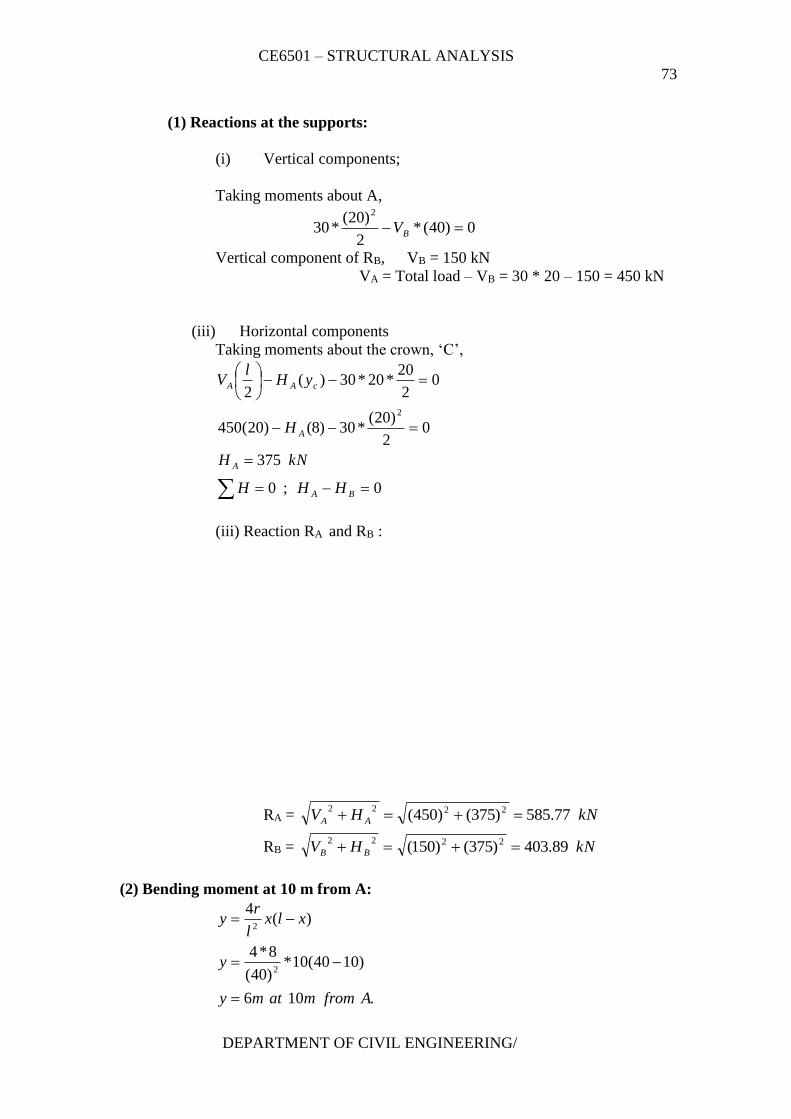
CE6501 – STRUCTURAL ANALYSIS
73
DEPARTMENT OF CIVIL ENGINEERING/
(1) Reactions at the supports:
(i) Vertical components;
Taking moments about A,
0)40(*2
)20(*30
2
BV
Vertical component of RB, VB = 150 kN
VA = Total load – VB = 30 * 20 – 150 = 450 kN
(iii) Horizontal components
Taking moments about the crown, ‘C’,
0;0
375
02
)20(*30)8()20(450
02
20*20*30)(
2
2
BA
A
A
cAA
HHH
kNH
H
yHl
V
(iii) Reaction RA and RB :
RA = kNHV AA 77.585)375()450( 2222
RB = kNHV BB 89.403)375()150( 2222
(2) Bending moment at 10 m from A:
.106
)1040(10*)40(
8*4
)(4
2
2
Afrommatmy
y
xlxl
ry
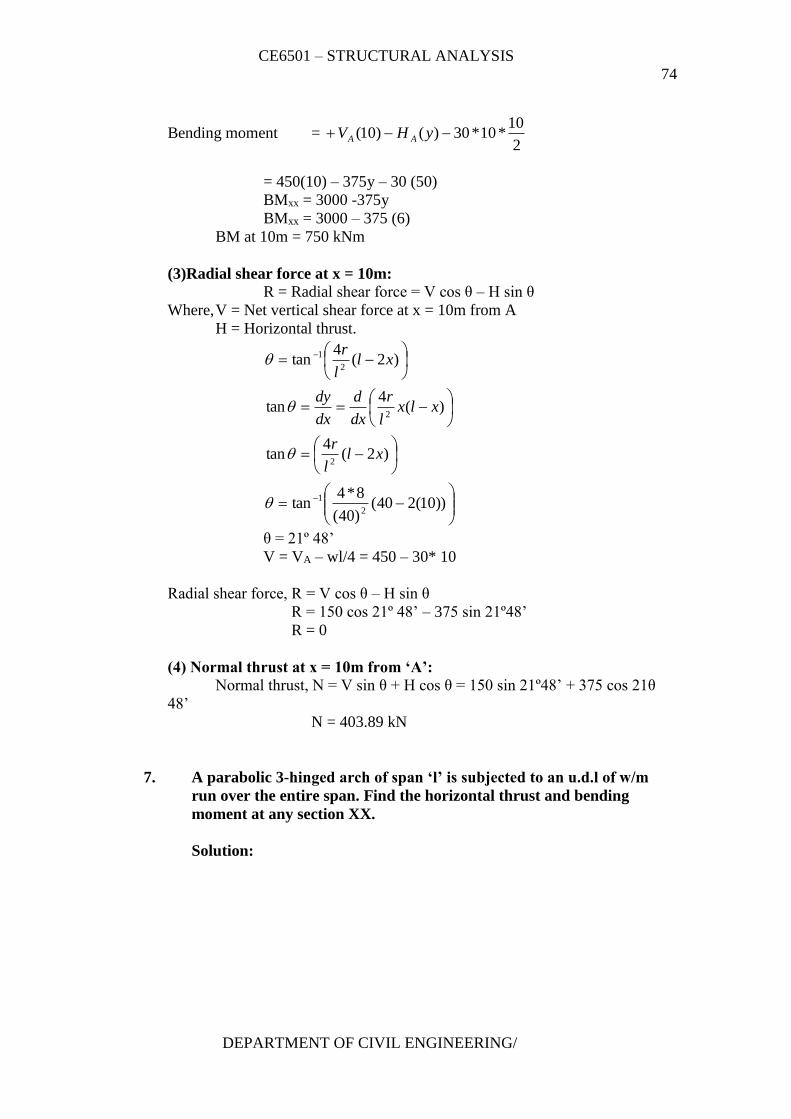
CE6501 – STRUCTURAL ANALYSIS
74
DEPARTMENT OF CIVIL ENGINEERING/
Bending moment = 2
10*10*30)()10( yHV AA
= 450(10) – 375y – 30 (50)
BMxx = 3000 -375y
BMxx = 3000 – 375 (6)
BM at 10m = 750 kNm
(3)Radial shear force at x = 10m:
R = Radial shear force = V cos θ – H sin θ
Where, V = Net vertical shear force at x = 10m from A
H = Horizontal thrust.
))10(240()40(
8*4tan
)2(4
tan
)(4
tan
)2(4
tan
2
1
2
2
2
1
xll
r
xlxl
r
dx
d
dx
dy
xll
r
θ = 21º 48’
V = VA – wl/4 = 450 – 30* 10
Radial shear force, R = V cos θ – H sin θ
R = 150 cos 21º 48’ – 375 sin 21º48’
R = 0
(4) Normal thrust at x = 10m from ‘A’:
Normal thrust, N = V sin θ + H cos θ = 150 sin 21º48’ + 375 cos 21θ
48’
N = 403.89 kN
7. A parabolic 3-hinged arch of span ‘l’ is subjected to an u.d.l of w/m
run over the entire span. Find the horizontal thrust and bending
moment at any section XX.
Solution:
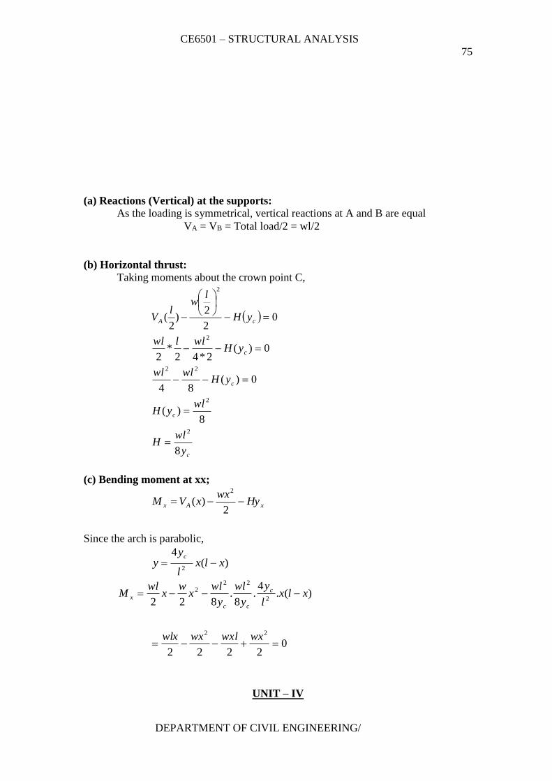
CE6501 – STRUCTURAL ANALYSIS
75
DEPARTMENT OF CIVIL ENGINEERING/
(a) Reactions (Vertical) at the supports:
As the loading is symmetrical, vertical reactions at A and B are equal
VA = VB = Total load/2 = wl/2
(b) Horizontal thrust:
Taking moments about the crown point C,
c
c
c
c
cA
y
wlH
wlyH
yHwlwl
yHwllwl
yH
lw
lV
8
8)(
0)(84
0)(2*42
*2
02
2)
2(
2
2
22
2
2
(c) Bending moment at xx;
xAx Hywx
xVM 2
)(2
Since the arch is parabolic,
)(4
2xlx
l
yy
c
)(.
4.
8.
822 2
222 xlx
l
y
y
wl
y
wlx
wx
wlM c
cc
x
02222
22
wxwxlwxwlx
UNIT – IV
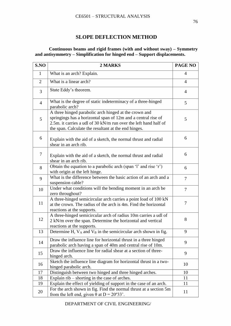
CE6501 – STRUCTURAL ANALYSIS
76
DEPARTMENT OF CIVIL ENGINEERING/
SLOPE DEFLECTION METHOD
Continuous beams and rigid frames (with and without sway) – Symmetry
and antisymmetry – Simplification for hinged end – Support displacements.
S.NO 2 MARKS PAGE NO
1 What is an arch? Explain. 4
2 What is a linear arch? 4
3 State Eddy’s theorem. 4
4 What is the degree of static indeterminacy of a three-hinged
parabolic arch? 5
5
A three hinged parabolic arch hinged at the crown and
springings has a horizontal span of 12m and a central rise of
2.5m. it carries a udl of 30 kN/m run over the left hand half of
the span. Calculate the resultant at the end hinges.
5
6
Explain with the aid of a sketch, the normal thrust and radial
shear in an arch rib.
6
7
Explain with the aid of a sketch, the normal thrust and radial
shear in an arch rib.
6
8 Obtain the equation to a parabolic arch (span ‘l’ and rise ‘r’)
with origin at the left hinge. 6
9 What is the difference between the basic action of an arch and a
suspension cable? 7
10 Under what conditions will the bending moment in an arch be
zero throughout? 7
11 A three-hinged semicircular arch carries a point load of 100 kN
at the crown. The radius of the arch is 4m. Find the horizontal
reactions at the supports.
7
12 A three-hinged semicircular arch of radius 10m carries a udl of
2 kN/m over the span. Determine the horizontal and vertical
reactions at the supports.
8
13 Determine H, VA and VB in the semicircular arch shown in fig. 9
14 Draw the influence line for horizontal thrust in a three hinged
parabolic arch having a span of 40m and central rise of 10m. 9
15 Draw the influence line for radial shear at a section of three-
hinged arch. 9
16 Sketch the influence line diagram for horizontal thrust in a two-
hinged parabolic arch. 10
17 Distinguish between two hinged and three hinged arches. 10
18 Explain rib – shorting in the case of arches. 11
19 Explain the effect of yielding of support in the case of an arch. 11
20 For the arch shown in fig. Find the normal thrust at a section 5m
from the left end, given θ at D = 20º33’. 11
CE6501 – STRUCTURAL ANALYSIS
77
DEPARTMENT OF CIVIL ENGINEERING/
21
A three-hinged parabolic arch has a horizontal span of 36m with
a central rise of 6m. A point load of 40 kN moves across the
span from the left to the right. What is the absolute maximum
positive bending moment that will occur in the arch?
12
22
A three-hinged parabolic arch of span 30m has a central rise of
5m. Find the increase in the rise of the arch if the temperature
rise through 30ºC. Take coefficient of linear expansion of the
arch material as 12 * 10-6 /ºC.
12
23 Determine the support reactions in the arch shown in fig. 13
S.NO 16 MARKS PAGE NO
1
A 3 hinged arch of span 40m and rise 8m carries concentrated
loads of 200 kN and 150 kN at a distance of 8m and 16m from
the left end and an udl of 50 kN/m on the right half of the span.
Find the horizontal thrust.
14
2
A parabolic 3-hinged arch carries a udl of 30kN/m on the left
half of the span. It has a span of 16m and central rise of 3m.
Determine the resultant reaction at supports. Find the bending
moment, normal thrust and radial shear at xx, 2m from left
support.
15
3
A parabolic 3-hinged arch carries loads as shown in fig.
Determine the resultant reactions at supports. Find the bending
moment, normal thrust and radial shear at D, 5m from A. What
is the maximum bending moment?
17
4
A 3-hinged arch is circular, 25 m in span with a central rise of
5m. It is loaded with a concentrated load of 10 kN at 7.5m from
the left hand hinge. Find the (a) Horizontal thrust (b) Reaction at
each end hinge (c) Bending moment under the load
19
5
A 3-hinged arch is circular, 25 m in span with a central rise of
5m. It is loaded with a concentrated load of 10 kN at 7.5m from
the left hand hinge. Find the following.
21
6
A three hinged circular arch of span 16m and rise 4m is
subjected to two point loads of 100 kN and 80 kN at the left and
right quarter span points respectively. Find the reactions at
supports. Find also the bending moment, radial shear and normal
thrust at 6m from left support.
23
7
A symmetrical three hinged parabolic arch of span 40m and rise
8m carries an udl of 30 kN/m over left of the span. The hinges
are provided at these supports and at the center of the arch.
Calculate the reactions at the supports. Also calculate the
bending moment, radial shear, and normal thrust at distance of
10 m from the left support.
2 5
TWO MARKS QUESTIONS AND ANSWERS
1. What are the assumptions made in slope – deflection method?
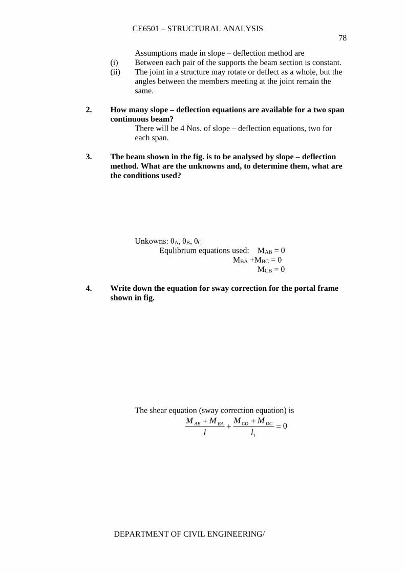
CE6501 – STRUCTURAL ANALYSIS
78
DEPARTMENT OF CIVIL ENGINEERING/
Assumptions made in slope – deflection method are
(i) Between each pair of the supports the beam section is constant.
(ii) The joint in a structure may rotate or deflect as a whole, but the
angles between the members meeting at the joint remain the
same.
2. How many slope – deflection equations are available for a two span
continuous beam?
There will be 4 Nos. of slope – deflection equations, two for
each span.
3. The beam shown in the fig. is to be analysed by slope – deflection
method. What are the unknowns and, to determine them, what are
the conditions used?
Unkowns: θA, θB, θC
Equlibrium equations used: MAB = 0
MBA +MBC = 0
MCB = 0
4. Write down the equation for sway correction for the portal frame
shown in fig.
The shear equation (sway correction equation) is
01
l
MM
l
MM DCCDBAAB
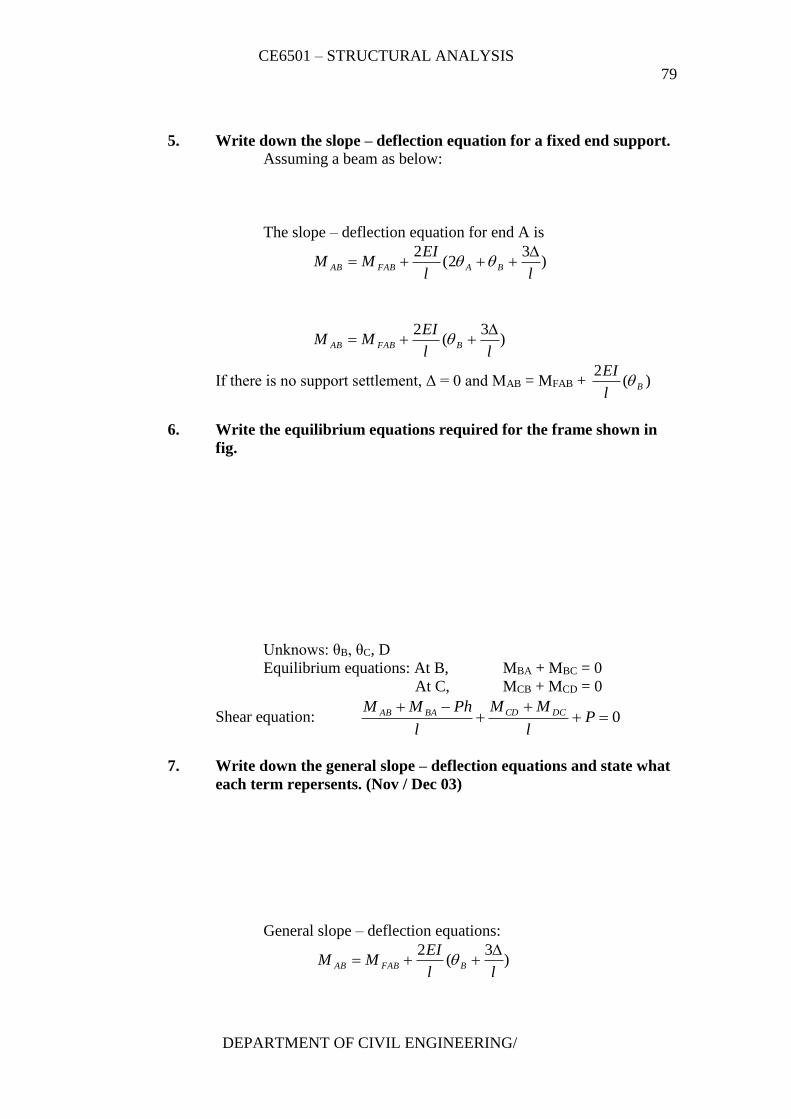
CE6501 – STRUCTURAL ANALYSIS
79
DEPARTMENT OF CIVIL ENGINEERING/
5. Write down the slope – deflection equation for a fixed end support.
Assuming a beam as below:
The slope – deflection equation for end A is
)3
2(2
ll
EIMM BAFABAB
)3
(2
ll
EIMM BFABAB
If there is no support settlement, Δ = 0 and MAB = MFAB + )(2
Bl
EI
6. Write the equilibrium equations required for the frame shown in
fig.
Unknows: θB, θC, D
Equilibrium equations: At B, MBA + MBC = 0
At C, MCB + MCD = 0
Shear equation: 0
Pl
MM
l
PhMM DCCDBAAB
7. Write down the general slope – deflection equations and state what
each term repersents. (Nov / Dec 03)
General slope – deflection equations:
)3
(2
ll
EIMM BFABAB
CE6501 – STRUCTURAL ANALYSIS
80
DEPARTMENT OF CIVIL ENGINEERING/
)3
(2
ll
EIMM BFABAB
MFAB , MFBA – Fixed end moment at A and B respectively due to
the given loading
θA, θB - Slopes at A and B respectively
Δ - Sinking of support A with respect to B.
8. Mention any three reasons due to which sway may occur in portal
frames. (Nov/Dec 03)
Sway in portal frames may occur due to
(i) Unsymmetry in geometry of the frame
(ii) Unsymmetry in loading
(iii) Settlement of one end of a frame.
9. Write down the fixed end moments for a beam carrying a central
clockwise moment.
Fixed end moments: 4
MMM FBAFAB
10. State the limitions of slope –deflection method.
(i) It is not easy to account for varying member sections.
(ii) It becomes very cumbersome when the unkown displacements
are large in number.
11. Why is slope – deflection method called a ‘displacement method’?
In slope – deflection method, displacements (like end slopes and
settlements) are treated as unknowns and hence the method is a
displacement method.
12. Define ‘degrees of freedom’.
In a structure, the number of independent joint displacements
that the structure can undergo is known as degrees of freedom.
13. In a continuous beam, one of the supports sinks. What will happen
to the span and support moments associated with the sinking
support?
Referring to fig. let support D sinks by Δ. This will not affect
span moments. Fixed end moments (support moments) will get
developed as under
CE6501 – STRUCTURAL ANALYSIS
81
DEPARTMENT OF CIVIL ENGINEERING/
2
1
6l
EIMM FDCFCD
2
1
6l
EIMM FEDFDE
14. A rigid frame is having totally 10 joints including support joints.
Out of slope – deflection and moment distribution methods, which
method would you prefer for analysis? Why?
Obviously moment distribution method is preferable.
If we use slope – deflection method, there would be ten (or
more) unkown displacements and an equal number of equilibrium
equations. In addition there would be 2 unknown support moments per
span and the same number of slope – deflection equations. Solving
them can be formidable task.
15. What is the basis on which a sway erquation is formed for
astructure?
Sway is dealt with in slope – deflection (likein moment
distribution method) byconsidering the horizontal equilibrium of the
whole frame taking into account the shears at base level of columns and
external horizontal forces.
16. Write the equilibrium for support B of the beam shown in fig.
Express values involved in terms of θB the rotation at B.
(i) Equilibrium equation
MAB + MBC = 0
(ii) MBC is given by the slope – deflecction equation
BFBCBCl
EIMM 2
2
(iii) MBA is the moment due to loading on the overhang BA.
17. List the unknown displacements involved in solving theframe in fig.
The unknown displacements are θB, θC and θD.
CE6501 – STRUCTURAL ANALYSIS
82
DEPARTMENT OF CIVIL ENGINEERING/
!8. What are the unknoen displacements involved in solving the frame
in fig?
The unknown displacements are θB, θC and θD.
19. What are the quantities in terms of which the unknown moments
are expressed in slope – deflection method?
In slope – deflection method, unknown moments are expressed in terms
of
(i) slopes (θ) and
(ii) deflection (Δ)
20. State the steps involved in slope – deflection method?
(i) For all members write down the fixed end moments due
to the given loading.
(ii) For each member write down the slope deflection
equations in trems of the joint rotations and
displacements. (θA, θB, …… ∆A, ΔB, ….. )
(iii) At every joint (A, B, C etc.) several members join. Each
member has moment acting on it. Write down joint
equilibrium equations.
CE6501 – STRUCTURAL ANALYSIS
83
DEPARTMENT OF CIVIL ENGINEERING/
SIXTEEN MARKS QUESTIONS AND ANAWERS
1. Analyse the continuous beam loaded as shown in fig. by the slope
deflection method and sketch the bending moment diagram, given:
2IAB = IBC = 2ICD = 2I
Solution:
IAB =ICD = I, IBC = 2I, θA = θD = 0 (A and D are fixed)
Unknowns θB, θC
(a) Fixed end moments:
Span AB:
MFAB = kNmwl
67.2612
4*20
12
22
kNmxwl
M FBA 67.2612
420
12
22
Span BC:
2
22
2
2
12
1
l
bWa
l
bWaM FBC
2
2
2
2
6
2*4*80
6
4*2*80FBCM
= -106.67 kNm
Span
CE6501 – STRUCTURAL ANALYSIS
84
DEPARTMENT OF CIVIL ENGINEERING/
Unit – V
1. What is the difference between absolute and relative
stiffness?
Absolute stiffness is represented in terms of E, I and l,
such as l
EI4
Relative stiffness is represented in terms of I and l,
omitting the constant E. Relative stiffness is the ratio of
stiffnesses of 2 or more members at a joint.
2. In a member AB, if a moment of -10 kNm is applied at A,
what is the moment carried over to B?
Carry over moment = Half the applied moment
Carried over moment to B = -10/2 = 5 kNm
3. What are the moments induced in a beam member, when
one end is given a unit rotation, the other end being fixed.
Express the answer in terms of l, E and I. What is the
moment at the near end called?
When θA = 1, fig.
MAB = l
EI4
MBA = l
EI2
MAB is the stiffness of AB at B.
4. A beam ABC is fixed at A and simply supported at B andC.
AB = BC = L. Flexural rigidities of AB and BC are 2EI and
EI respectively. Find the distribution factors at joint B if no
moment is to be transferred to support C.
Joint B:
CE6501 – STRUCTURAL ANALYSIS
85
DEPARTMENT OF CIVIL ENGINEERING/
Relative stiffness:
l
I
l
I 21 for BA kBA = 2
l
I
l
Ix
4
3
4
3 1 for BC kBC = 3/4 = 0.75
Distribution factors:
DF for BA: 727.075.02
2
BCBA
BA
kk
k
DF for BC: 273.075.02
75.0
BABC
BC
kk
k
5. Explain “carry over factor” with a sketch.
Carry over factor is the ratio of moment induced at the
far end and the moment applied at the near end.
Considering prismatic beams as in fig.
Carry over factor, C.O.F. = (M/2)/M =1/2
If the far end is simply supported, there is no carry over
moment. Hence the carry over factor is zero.
6. Three members meeting at a rigid joint carry moments 5
kNm (clokwise), 10 kNm (clockwise) and 9 kNm (counter
clockwise). What moments should be applied at the joint O
for achieving equilibrium?
Unblanced moment = 5 + 10 – 9
= 6 kNm
Moment to be applied at O for eqilibrium
= 6 kNm (counter clockwise)
CE6501 – STRUCTURAL ANALYSIS
86
DEPARTMENT OF CIVIL ENGINEERING/
7. Distribute a moment of 6 kNm at a joint among three
members whose relative stiffnesses are 1/6, 1/3 and ½.
Member Relative
stiffness
Sum Distribution
factor
Moment in
member
(kNm)
1 1/6 1\6 +1/3 ½ =
(1+2+3)/6 =6/6
=1
(1/6)/1=1/6 (1/6)*6=1
2 1/3 (1/3)/1=1/3 (1/3)*6 = 2
3 1/2 (1/2)/1=1/2 (1/2)*6=3
8. In the above question, if the far ends of the 3 members were
fixed, how much moment will be carried over to the far end
of each member?
Member No. Moment shared Moment carried over to
the other end
1 1 kNm 0.5 kNm
2 2 kNm 1.0 kNm
3 3 kNm 1.5 kNm
9. Define the term ‘sway’.
Sway is the lateral movement of joints in a portal frame
due to the unsymmetry dimensions, loads, moments of inertia,
end conditions, etc.
10. What are the situations wherein sway will occur in portal
frames?
(i) Eccentric or unsymmetric loading
(ii) Unsymmetrical geometry
(iii) Different end conditions of the columns
(iv) Non- uniform section of the members
(v) Unsymmetrical settlement of supports
(vi) A combination of the above.
11. What is the ratio of sway moments at column heads when
one end is fixed and the other end hinged? Assume that the
length and M.I. of both legs are equal.
Assuming the frame to sway to the right by d.
CE6501 – STRUCTURAL ANALYSIS
87
DEPARTMENT OF CIVIL ENGINEERING/
Ratio of sway moments 23
6
2
2
l
EI
l
EI
M
M
CD
BA
12. Taking advantages of symmetry, find the final moment MBC
in the beam in fig.
The beam is equivalent to the one shown in fig. above
-MFAB = MFBA = 12
2
0wl
Carry over from A to B = - 24
2
0wl
MBA = 12
2
0wl-
24
2
0wl =
24
2
0wl = MBC