UNIT I Alternative Fuels: Classification of Alternative Fuelsfmcet.in/AUTO/AT2022_uw.pdf ·...
69
1 UNIT I Alternative Fuels: Alternative fuel as defined here, is any material or substance, other than petroleum (oil), which is consumed to provide energy to power an engine. Some alternative fuels are biodiesel, ethanol, butanol, chemically stored electricity (batteries and fuel cells), hydrogen, methane, natural gas, wood, and vegetable oil. The need for the development of alternative fuel sources has been growing due to concerns that the production of oil will no longer supply the demand. Classification of Alternative Fuels Some of these come into the category of renewable energy. Renewable energy includes electricity generation for the home, while the term "alternative fuels" tends to refer to mobile energy. Some alternative fuels and the cars they power are: Gasoline type biofuels • Butanol as a direct replacement for gasoline • Ethanol or mixtures with gasoline E85, • Hydrogen internal-combustion car (see hydrogen car) Diesel type biofuels • Hempseed oil fuel or other Straight vegetable oils • Biodiesel Others with internal combustion • Natural gas, compressed or liquified • Propane (aka LPG, LP gas) • Synfuel synthetic fuels • Oil shale, • Plug-in hybrid electric vehicle External combustion • Steam engine cars (like the Stanley Steamer) • Coal-oven steam cars • Organic waste fuel • Wood gas on board gasification No combustion • Electric vehicle
Transcript of UNIT I Alternative Fuels: Classification of Alternative Fuelsfmcet.in/AUTO/AT2022_uw.pdf ·...
1
UNIT I Alternative Fuels: Alternative fuel as defined here, is any material or substance, other than petroleum (oil), which is consumed to provide energy to power an engine. Some alternative fuels are biodiesel, ethanol, butanol, chemically stored electricity (batteries and fuel cells), hydrogen, methane, natural gas, wood, and vegetable oil. The need for the development of alternative fuel sources has been growing due to concerns that the production of oil will no longer supply the demand. Classification of Alternative Fuels
Some of these come into the category of renewable energy. Renewable energy includes electricity generation for the home, while the term "alternative fuels" tends to refer to mobile energy. Some alternative fuels and the cars they power are:
Gasoline type biofuels
• Butanol as a direct replacement for gasoline • Ethanol or mixtures with gasoline E85, • Hydrogen internal-combustion car (see hydrogen car)
Diesel type biofuels
• Hempseed oil fuel or other Straight vegetable oils • Biodiesel
Others with internal combustion
• Natural gas, compressed or liquified • Propane (aka LPG, LP gas) • Synfuel synthetic fuels • Oil shale, • Plug-in hybrid electric vehicle
External combustion
• Steam engine cars (like the Stanley Steamer) • Coal-oven steam cars • Organic waste fuel • Wood gas on board gasification
No combustion
• Electric vehicle

2
• Solar cell powered or charged electric cars • Tesla's electric car (with antenna) • Hydrogen fuel cell liquefied or compressed hydrogen • MAGLEV with induction drive (a variety of electric mass transit) • Air car working on compressed air.
Properties of Alternative Fuels: Ethanol: Essentially 100 percent pure grain alcohol made unfit to drink, ethanol is produced by fermenting plant sugars. It can be made from corn, potatoes, wood, waste paper, wheat, brewery waste, and many other agricultural products and food wastes. Anything containing sugar, starch, or cellulose can be fermented and distilled into ethanol. More than 90 percent of U.S. ethanol production comes from corn. Pure ethanol is rarely used for transportation; usually it is mixed with gasoline. The most popular blend for light-duty vehicles is known as E85, which is 85 percent ethanol and 15 percent gasoline. Heavy-duty trucks typically use E95 (ethanol blended with five percent unleaded gasoline) and E93 (ethanol blended with five percent methanol and two percent kerosene). For many years, ethanol has also been used as a 10 percent mixture with gasoline in a blend called “gasohol” or E10 to reduce carbon monoxide emissions during winter. Finally, ethanol is often blended in gasoline as an oxygenate to meet clean fuel requirements. The technology to produce ethanol is well established, and all the resources needed to produce it can be supplied domestically. Performance: Ethanol vehicles exhibit the same power, acceleration, payload, and cruise speed as conventionally fueled vehicles. In addition, ethanol use has several benefits. It has a higher octane rating than gasoline, which reduces engine “knock” and can result in higher energy efficiency. Ethanol also absorbs moisture and helps prevent gas-line freeze-up in cold weather, preventing the need to add expensive and possibly harmful fuel additives. In addition, ethanol has some detergent properties that reduce buildup, which keeps engines running smoothly and fuel injection systems clean for better performance. On the other hand, ethanol vehicles have about 75 to 90 percent of the range of comparable gasoline vehicles and might require more frequent fueling. Some auto manufacturers are installing larger fuel tanks in E85 vehicles to prevent this inconvenience. Another potential concern is that ethanol is a more volatile fuel than gasoline, with a low volatility in winter and a high volatility in summer. In addition, ethanol does not mix well with diesel fuel. Consumers with diesel vehicles who wish to use ethanol should completely replace diesel fuel with pure ethanol or use a special injection method.
3
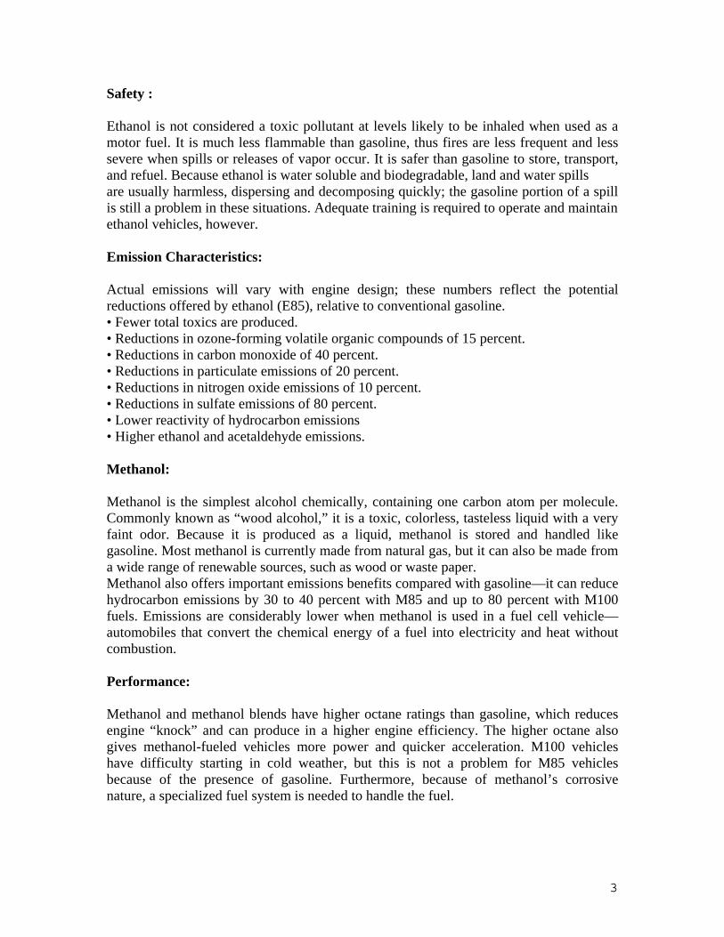
Safety : Ethanol is not considered a toxic pollutant at levels likely to be inhaled when used as a motor fuel. It is much less flammable than gasoline, thus fires are less frequent and less severe when spills or releases of vapor occur. It is safer than gasoline to store, transport, and refuel. Because ethanol is water soluble and biodegradable, land and water spills are usually harmless, dispersing and decomposing quickly; the gasoline portion of a spill is still a problem in these situations. Adequate training is required to operate and maintain ethanol vehicles, however. Emission Characteristics: Actual emissions will vary with engine design; these numbers reflect the potential reductions offered by ethanol (E85), relative to conventional gasoline. • Fewer total toxics are produced. • Reductions in ozone-forming volatile organic compounds of 15 percent. • Reductions in carbon monoxide of 40 percent. • Reductions in particulate emissions of 20 percent. • Reductions in nitrogen oxide emissions of 10 percent. • Reductions in sulfate emissions of 80 percent. • Lower reactivity of hydrocarbon emissions • Higher ethanol and acetaldehyde emissions. Methanol: Methanol is the simplest alcohol chemically, containing one carbon atom per molecule. Commonly known as “wood alcohol,” it is a toxic, colorless, tasteless liquid with a very faint odor. Because it is produced as a liquid, methanol is stored and handled like gasoline. Most methanol is currently made from natural gas, but it can also be made from a wide range of renewable sources, such as wood or waste paper. Methanol also offers important emissions benefits compared with gasoline—it can reduce hydrocarbon emissions by 30 to 40 percent with M85 and up to 80 percent with M100 fuels. Emissions are considerably lower when methanol is used in a fuel cell vehicle—automobiles that convert the chemical energy of a fuel into electricity and heat without combustion. Performance: Methanol and methanol blends have higher octane ratings than gasoline, which reduces engine “knock” and can produce in a higher engine efficiency. The higher octane also gives methanol-fueled vehicles more power and quicker acceleration. M100 vehicles have difficulty starting in cold weather, but this is not a problem for M85 vehicles because of the presence of gasoline. Furthermore, because of methanol’s corrosive nature, a specialized fuel system is needed to handle the fuel.
4
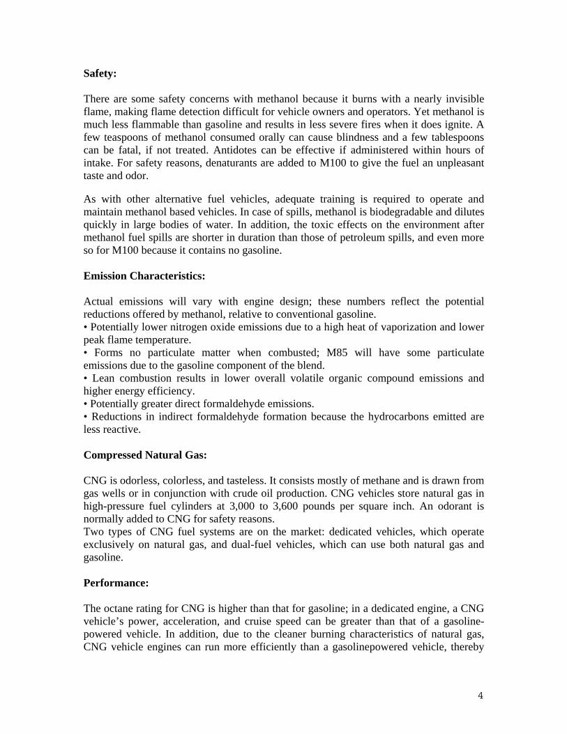
Safety: There are some safety concerns with methanol because it burns with a nearly invisible flame, making flame detection difficult for vehicle owners and operators. Yet methanol is much less flammable than gasoline and results in less severe fires when it does ignite. A few teaspoons of methanol consumed orally can cause blindness and a few tablespoons can be fatal, if not treated. Antidotes can be effective if administered within hours of intake. For safety reasons, denaturants are added to M100 to give the fuel an unpleasant taste and odor. As with other alternative fuel vehicles, adequate training is required to operate and maintain methanol based vehicles. In case of spills, methanol is biodegradable and dilutes quickly in large bodies of water. In addition, the toxic effects on the environment after methanol fuel spills are shorter in duration than those of petroleum spills, and even more so for M100 because it contains no gasoline. Emission Characteristics: Actual emissions will vary with engine design; these numbers reflect the potential reductions offered by methanol, relative to conventional gasoline. • Potentially lower nitrogen oxide emissions due to a high heat of vaporization and lower peak flame temperature. • Forms no particulate matter when combusted; M85 will have some particulate emissions due to the gasoline component of the blend. • Lean combustion results in lower overall volatile organic compound emissions and higher energy efficiency. • Potentially greater direct formaldehyde emissions. • Reductions in indirect formaldehyde formation because the hydrocarbons emitted are less reactive. Compressed Natural Gas: CNG is odorless, colorless, and tasteless. It consists mostly of methane and is drawn from gas wells or in conjunction with crude oil production. CNG vehicles store natural gas in high-pressure fuel cylinders at 3,000 to 3,600 pounds per square inch. An odorant is normally added to CNG for safety reasons. Two types of CNG fuel systems are on the market: dedicated vehicles, which operate exclusively on natural gas, and dual-fuel vehicles, which can use both natural gas and gasoline. Performance: The octane rating for CNG is higher than that for gasoline; in a dedicated engine, a CNG vehicle’s power, acceleration, and cruise speed can be greater than that of a gasoline-powered vehicle. In addition, due to the cleaner burning characteristics of natural gas, CNG vehicle engines can run more efficiently than a gasolinepowered vehicle, thereby

5
extending the life of the vehicle. In heavy-duty vehicles, CNG engines are also generally less noisy than diesel engines. Safety: Although CNG is a flammable gas, it has a narrow flammability range, making it an inherently safe fuel. Strict safety standards make CNG vehicles as safe as gasoline-powered vehicles. In the event of a spill or accidental release, CNG poses no threat to land or water; it is nontoxic. CNG also disperses rapidly, minimizing ignition risk relative to gasoline. Natural gas is lighter than air and will not pool as a liquid or vapor on the ground. Nevertheless, leaks indoors may form a flammable mixture in the vicinity of an ignition source. CNG is primarily methane, however, which is a greenhouse gas that could contribute to global climate change if leaked. Methane is slightly soluble in water and under certain environmental conditions (anaerobic) does not biodegrade; If excess amounts accumulate, the gas can bubble from the water, possibly creating a risk of fire or explosion. Reported incidences of bus fires are related to engine failures, not the use of natural gas. Natural gas buses have onboard gas detectors and other safety devices, such as tank safety valves that allow fuel flow only when the engine is keyed on. Also, the tanks must be inspected and approved by the U.S. Department of Transportation after certain periods of use. There are some different safety concerns with CNG buses than diesel fuel buses, such as greater breaking distance due to increased fuel storage system weight. This is a relatively small concern, however, because the fuel system is a small fraction of a bus’ total weight. CNG buses also might accelerate slower than their diesel counterparts. Emission Characteristics: Actual emissions will vary with engine design; these numbers reflect the potential reductions offered by compressed natural gas, relative to conventional gasoline. • Reductions in carbon monoxide emissions of 90 to 97 percent, and reductions in carbon dioxide emissions of 25 percent. • Reductions in nitrogen oxide emissions of 35 to 60 percent. • Potential reductions in nonmethane hydrocarbon emissions of 50 to 75 percent. • Fewer toxic and carcinogenic pollutants and little to no particulate matter produced. • No evaporative emissions in dedicated engines (such as those associated with gasoline or diesel). Liquefied Natural Gas: LNG is odorless, colorless, noncorrosive, and nontoxic. When extracted from underground reserves, natural gas is composed of approximately 90 percent methane. During the liquefaction process, oxygen, carbon dioxide, sulfur compounds, and water are removed, purifying the fuel and increasing its methane content to almost 100 percent. As a result, LNG-fueled vehicles can offer significant emissions benefits compared with older diesel-powered vehicles, and can significantly reduce carbon monoxide and particulate emissions as well as nitrogen oxide emissions.

6
Performance: There are no discernible differences in LNG vehicle performance, operation, and utility when compared with diesel. The high ignition quality of LNG is similar to that of diesel, providing for similar durability and engine life overall Safety: A LNG vehicle parked indoors and unmoved for a week or more will vent a flammable gas mixture that could catch fire in the vicinity of an ignition source. To address this safety issue, LNG use should be restricted to frequently driven fleet vehicles or to vehicles stored outdoors. Only trained personnel should service the vehicles. In addition, refueling vehicles with LNG requires training because of the fuel’s ultra low temperature. It can cause frostbite if it contacts skin. Since LNG is almost 100 percent Methane—a greenhouse gas—it can also contribute to global climate change if accidentally released into the air. Methane is slightly soluble in water and, under certain environmental conditions (anaerobic), it does not bio-degrade. If excess amounts accumulate, the gas can bubble from the water, possibly creating a risk of fire or explosion. Emission Characteristics: Actual emissions will vary with engine design; these numbers reflect the potential reductions offered by LNG relative to diesel. • Production of half particulate matter of average diesel vehicles. • Can significantly reduce carbon monoxide emissions. • Reductions of nitrogen oxide and volatile organic hydrocarbon emissions by 50 percent or more. • Potential reductions in carbon dioxide emissions of 25 percent depending on the source of the natural gas. • Drastic reductions in toxic and carcinogenic pollutants. • Increase in methane emissions. Liquefied Petroleum Gas or LPG Propane (otherwise known as Liquefied Petroleum Gas or LPG) is a byproduct of natural gas processing and petroleum refining. In its natural state, propane is a colorless, nontoxic gas—at least 90 percent propane, 2.5 percent butane and higher hydrocarbons, and the balance ethane and propylene. An odorant is added to the gas so it can be detected for safety reasons. Under moderate pressure, propane gas turns into a liquid mixture, making it easier to transport and store in vehicle fuel tanks. Compared with gasoline, propane can lower carbon dioxide, carbon monoxide, and other toxic emissions.

7
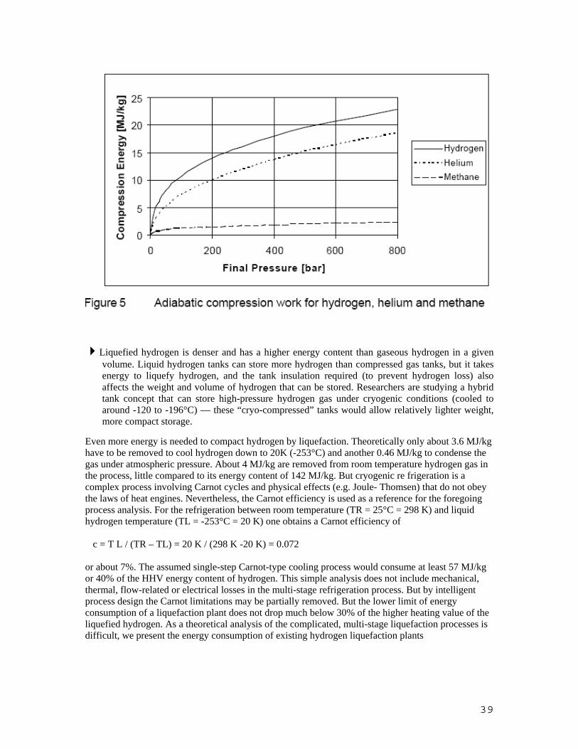
Performance: Those who drive propane-powered vehicles assert that there are no significant driving differences between dedicated propane vehicles and gasoline- powered vehicles. In fact, propane vehicles have a higher octane rating than gasoline, allowing for a higher compression ratio in the engine and greater engine efficiency. This also reduces engine “knock” and allows the engine to run more smoothly. Because the fuel is already in a gaseous state, it mixes readily with air in the combustion chamber to allow for nearly complete combustion. This reduces certain exhaust emissions, such as carbon monoxide, and minimizes problems with starting the vehicles in cold weather. Safety: Propane in its liquid state has the lowest flammability range of any alternative fuel, which reduces the chances of a vehicle fire. Because it becomes a gas when leaked, however, it is more likely to ignite than gasoline and other liquid fuels; propane gas when leaked can fill a room and form a flammable layer against the ground or floor. Nevertheless, in case of a spill outdoors, propane is nontoxic, slightly soluble and biodegrades rapidly in soil, water or air. If stored in an enclosed space, proper ventilation and leak detection sensors are needed to increase safety, since the gas can displace the air necessary for breathing. Emission Characteristics: Actual emissions will vary with engine design; these numbers reflect the potential reductions offered by propane, relative to conventional gasoline. • Potentially lower toxic, carbon dioxide (CO2), carbon monoxide (CO), and nonmethane hydrocarbon (NMHC) emissions. • Rich calibration shows high NMHC and CO emissions, but lower nitrogen oxide (NOx) emissions. • Lean calibration shows slightly higher NOx emissions, but lower CO and NHMC emissions. Bio-diesel: Today, the diesel engine is still capable of running on “biodiesel” fuel, which can be produced from a variety of renewable sources, including soybean oil, canola oil, sunflower oil, cottonseed oil, and animal fats. These sources can be obtained from agricultural feedstocks or by recycling used oil such as cooking grease. Most biodiesel produced in the United States is made from soybean oil due to this feedstock’s abundance. Biodiesel is usable in its pure form, known as “neat biodiesel” or B100. In addition, it is available in various blends with petrodiesel, the most common of which is known as B20 (20 percent biodiesel and 80 percent petrodiesel). It is also used in smaller percentages as a lubricating fuel additive.

8
Performance: Biodiesel maintains the same payload capacity and range as conventional diesel, and provides similar horsepower, torque, and fuel economy. Biodiesel has a higher cetane number than conventional diesel, which increases the engine’s performance. It also serves as a high-quality lubricant and can enhance the life of heavyduty engines. Biodiesel vehicles can have cold start problems relative to petrodiesel, but this is more of an issue for B100 than B20 fuels. For example, B20 freezes at temperatures 3°F to 5°F higher than petrodiesel, but it has been used in upper Wisconsin and Iowa during -25°F weather with no reported problems. B100 will begin to freeze at 25°F, however. Vehicle owners can solve cold start problems with biodiesel in the same manner as with conventionally fueled vehicles (e.g., using engine block or fuel filter heaters or storing the vehicles near or in a building). Safety: Biodiesel is biodegradable, which means it dissipates quickly after a spill. Biodiesel has a high flashpoint and low volatility so it does not ignite as easily as petrodiesel, which increases the margin of safety in fuel handling. In fact, it degrades four times faster than petrodiesel and is not particularly soluble in water. It is nontoxic, which makes it safe to handle, transport, and store. When blended with petrodiesel, the spill’s petrodiesel portion is still a problem, but less so than with 100 percent petrodiesel. As with all vehicles, adequate training is recommended to operate and maintain biodiesel vehicles. Emission Characteristics: Actual emissions will vary with engine design; these numbers reflect the potential reductions offered by a biodiesel blend (B20) and pure biodiesel (B100), relative to conventional diesel. • Reductions in carbon monoxide emissions of 10 percent (B20) and 50 percent (B100). • Reductions in particulate emissions of 15 percent (B20) and 70 percent (B100). • Reductions in total hydrocarbon emissions of 10 percent (B20) and 40 percent (B100). • Reductions in sulfate emissions of 20 percent (B20) and 100 percent (B100). • Increases in nitrogen oxide emissions of 2 percent (B20) and 9 percent (B100). • No change in methane emissions using either B20 or B100.

9
Methane Propane LNG Gasoline Diesel Hydrogen Methanol Ethanol
Formula CH4 C3H8 CH4 C8 H18 C12H26 H2 CH3OH C2H5OH
Research Octane Number 130 112 130 91-98 N.A 130+ 107 108
Motor Octane Number 130 97 130 83-90 N.A N.A 91 92
Cetane Number -10 5-10 -10 8-14 40-65 N.A 3 8
Density of Liquid Fuel(kg/lt) N.A 0.509 0.421 0.746 0.808 0.0708 0.79 0.783
Density of Gas (kg/m3) 0.6512 0.508 N.A 4.4 0.0838
Boiling Point (C) -162 -42 -162 27-240 -252.7
Lower Heating Value (kj/kg) 49,913 46,238 49,913 42,661 43,419 119,444 19,859 26,855
Energy Content (Volume) (BTU/gallon) 121,459 84,448 28,287 114,194 125,881 N/A N/A 57,449
Energy Compared to Gasoline 65% 72% 66% 100% 113% 26% 47% 66%
Energy Compared to Diesel 57% 64% 60% 88% 100% 23% 41% 58%
Stoichometric A/F Ratio (mass) 17.3 15.7 17.3 14.7 15 34.3 6.5 9
Heat of Vaporization (kj/kg) 507 423 507 355 286 N.A 1186 842
Energy of Stoich. Mixture (Vapor) 3.58 3.79 3.58 3.55 3.61 3.58 3.45 3.46
Wobbe Number (Mj/m3) 50.66 74.7 50.66 N.A N.A
Autoignition Temperature (C) 540 482 450 257 316 574 464 423
Peak Flame Temperature (C) 1790 1990 1790 1977 2054 2045
Spark Ignition Energy (mj) 0.29 0.305 0.29 0.24 0.24 0.02
Flammability Limits (vol %) 5.3-15 2.1- 10.4 1.4- 7.6 0.6- 5.5 4-75
Max. Burning Velocity in NTP air (cm/s) 37-45 43-52 37-45 37-43
Specific Gravity at NTP (60 deg F) 0.55 1.52 0.55 2-4 4-6
Reid Vapor Pressure (psi) 2400 208 8-15 0.2 4.6 2.3
Flame Visibility, relative 0.6 0.6 0.6 1 1
Flash Point (F) -300 -100 to -150 -306 -45 165 52 55
Properties of Some Alternative Fuels

10
UNIT II Alcohols Properties of Alcohol as engine fuels:
1. Air Fuel Ratio
Because the alcohols contain oxygen in their chemical form, they require less air to complete combustion. (A/F ratio is low with alcohol fuels). For methanol it is 6.4 : 1 and ethanol it is 9 : 1.
2. Theory of Combustion
The ratio of moles of product and reactants for alcohols is higher compared to gasoline. Assuming all the fuels enter the engine completely evaporated, the fuel giving largest number of moles of products per mole of reactant should produce more pressure after combustion and hence power in the cylinder, all other factors being equal. By this it is clear that alcohol will produce more power than gasoline
Fuel Ratio Gasoline 1.058 Methanol 1.061 Ethanol 1.065
3. Calorific Value One of the most important properties of a fuel is the amount of energy obtained from it when it is burned. All of the alcohols contain an oxygen atom bonded to a hydrogen atom in the hydroxyl radical. When the alcohol is burned, the hydroxyl combines with a hydrogen atom to form a molecule of water. Thus, the oxygen contained in the alcohol contributes nothing to the fuel value. The relative atomic weights of the atoms involved are: hydrogen, 1 ; carbon, 12; and oxygen, 16. Since methyl alcohol has an atomic weight of 32, half the molecule cannot be "burned" and does not contribute any fuel value. As expected, methanol has less than half the heat value (expressed in Btu/lb) of gasoline. Ethanol, with 35% oxygen, is slightly better with 60% of the heat value of gasoline. To generate equal amount of energy as that of gasoline, methanol has to be supplied 2.2 times as that of gasoline and ethanol 1.64 times greater. If the heating value of methyl and ethyl alcohol were considered alone, they would appear to be poor choices as motor fuels. However, other redeeming qualities such as "latent heat of vaporization" and anti-knock values make alcohol fuels superior, in some ways, to gasoline.

11
4. Volatility
A fuel’s ability to vaporize or change from liquid to vapor is referred to as its volatility. Gasoline and other liquid fuels such as alcohols are used in a variety of engines with large variations in operating conditions and under a wide range of atmospheric temperatures and barometric pressures. Therefore, the volatility characteristics of a spark ignition (SI) engine fuel are of prime importance. Fuels that do not vaporize readily may cause hard starting of cold engines and poor vehicle driveability during warm-up and acceleration. Conversely, fuels that vaporize too readily at higher operating temperatures will cause too much vapor to form causing a decrease in fuel flow to the engine (known as “vapor lock’). These extremes of difficult starts on the one hand and vapor lock on the other can be minimized by changing fuel volatility specifications for seasonal, geographical, and elevation considerations. Therefore, it is important that a fuel’s tendency to evaporate is controlled to certain standards.
Gasoline is composed of a number of compounds having boiling points ranging from approximately 27- 225°C(80-437°F).Unlike gasoline, methanol and ethanol are single compounds that boil at 64.7°C (149°F) and 78.3°C (173°F), respectively. In fuel applications, alcohols lack the light fractions with boiling points near 38°C (100°F) which are essential for starting spark-ignited engines in severe cold.
5. Vapor Pressure
A fuel’s tendency to vaporize is measured by Reid Vapor Pressure (RVP), The Reid Vapor Pressure or RVP (ASTM D 323) is a measurement of a fuel’s front-end volatility. The determination of RVP is performed by submerging a fuel sample (sealed in a flask) in a 100°Fwater bath. More volatile fuels will vaporize

12
more readily, producing higher pressure readings. Less volatile fuels will not create as much vapor, therefore creating lower pressure readings.
Alcohols have a very low vapor pressure because of their high boiling point and high latent heat of vaporization. This makes alcohol unsuitable for severe cold environment operation. When alcohol is added to gasoline in small amount it tends to increase the RVP of the fuel
6. Water Content Gasoline and water free alcohol are miscible in all proportions over a wide range of temperatures. However, even a small addition of water to this blended fuel causes separation of the alcohol and gasoline which can be one of most difficult problems for the blends to be used as motor fuels.
13
7. Latent Heat of Vaporization
When a liquid is at its boiling point, a certain amount of additional heat is needed to change the liquid to a gas. This additional heat is the latent heat of vaporization. Alcohols have higher Latent Heat of Vaporization. In an engine, vaporization of the gasoline fuel/air mixture results in a temperature drop of about 4.5 degrees Celsius. Under similar conditions, the temperature drop for ethyl alcohol will be more than twice that of gasoline, and for methanol the drop will be over three times as great. These temperature drops result in a considerably greater "mass density" of the fuel entering the engine for alcohol as compared to gasoline. The result is a greatly increased efficiency for alcohol fuels. To visualize why, remember that at a given pressure, the amount of space a gas occupies is directly proportional to the temperature. For example, if one kg of a gas fits into a certain container at a given pressure and the temperature is cut in half, the container will now hold two kg of the gas at the same pressure. In an engine, a stoichiometric mixture of methanol and air would be over three times colder than the same gasoline/air mixture. This means that there is now over three times (by weight) as much methanol in the cylinder. Now, even though methanol has only half the heat value of gasoline, the net gain in "volumetric mass efficiency" is over three times. So, for example, if the gasoline/air mixture in a given engine cylinder produces 100 kJ on each stroke, the same engine would produce kJ Btu per stroke with methanol. This power gain due to increased volumetric mass efficiency is the primary reason for the popularity of methyl alcohol.
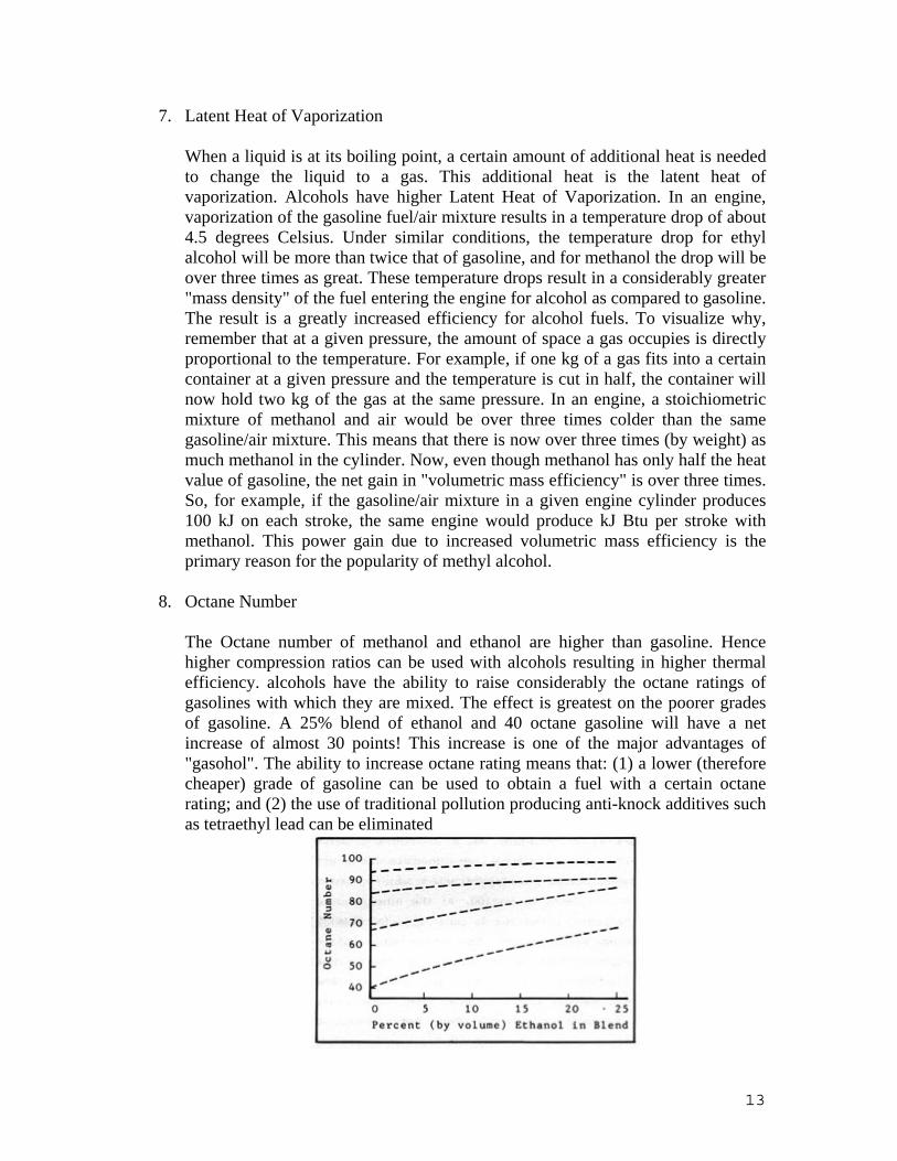
8. Octane Number The Octane number of methanol and ethanol are higher than gasoline. Hence higher compression ratios can be used with alcohols resulting in higher thermal efficiency. alcohols have the ability to raise considerably the octane ratings of gasolines with which they are mixed. The effect is greatest on the poorer grades of gasoline. A 25% blend of ethanol and 40 octane gasoline will have a net increase of almost 30 points! This increase is one of the major advantages of "gasohol". The ability to increase octane rating means that: (1) a lower (therefore cheaper) grade of gasoline can be used to obtain a fuel with a certain octane rating; and (2) the use of traditional pollution producing anti-knock additives such as tetraethyl lead can be eliminated

14
Combustion Characteristics of Alcohol
1. Flammability limits Alcohols have extended flammability limits, which mean that they can be
combusted with very leaner mixture also. This results in the reduction of emissions also.
2. High Pressure development
Alcohols during combustion produce a great number of product moles per mole of fuel burnt, therefore, higher pressure are achieved. This results in the increase in work output and hence the power of the engine.
3. High laminar burning velocity A faster burning chamber with its shorter burn time permits operation with more excess air or leaner mixtures, and provides a more repeatable combustion pattern, thus providing lower cycle-by-cycle variability over the entire operating range. The higher laminar burning velocities of alcohols makes it suitable for the faster burning chamber.
The higher flame speed, giving earlier energy release in the power stroke, results in a power increase of 11% at normal conditions and up to 20% at the higher levels of a compression ratio. The optimum spark setting will depend on the rate of flame development and propagation and the length of the flame travel path across the combustion chamber. The use of both ethanol and methanol has shown to decrease the spark advance required for MBT. As shown in Figure below for methanol, as the percentage of alcohol increases in the gasoline/alcohol mixture, less spark advance is required and the MBT timing shifts toward Top Dead Center or TDC. This is an indication of methanol’s higher burning velocity. In the drawing, DBTDC signifies Degrees before Top Dead Center

15
4. Non Luminous flame Low flame luminosity of methanol causes safety concern. The formation of submicroscopic soot particles during the combustion process provide the luminosity of a carbon containing fuel. These particles which are heated by the flame emit light at visible wavelengths in a process called gray-body radiation. When methanol burns, it has a cooler flame and a few soot particles occur. The tendency to soot increases with molecular weight. Therefore, methanol produces less soot than ethanol. The flame of methanol radiates at infrared wavelengths due to the absence of gray-body radiation. A visible luminous flame during the combustion process is a desirable fuel characteristic in point of safety view in order to detect of the flame in the event of an accidental fire. Non-luminous flame can cause danger to people close to the fire. Some additives can improve the luminosity of methanol.
5. Lower Adiabatic Flame Temperature
The adiabatic flame temperature of alcohols is lower compared with the gasoline.

16
In conjunction with lower flame temperature, about 10% less heat is lost to the engine coolant. The lower flame temperature of alcohols results in much lower NOx (Nitrogen Oxides) emissions.
Performance of Alcohol Engines Effect of Compression Ratio
Compression ratio (CR) is defined as the maximum cylinder volume (when the piston is at the bottom of its reciprocating path) divided by the minimum cylinder volume (when the piston is at Top Dead Center or TDC). Increasing the compression ratio is a known method of increasing fuel economy by improving thermal efficiency. Because of their higher octane ratings, alcohol fuels allow the use of higher compression ratios. However, the introduction of high compression ratios has two potential drawbacks: an increased tendency to knock and higher NOx emissions. Alcohol blends can help solve the problem of knock at elevated compression ratios. Using a variable-compression ratio, single-cylinder engine, the effect of methanol content on the knock-limited compression ratio (KLCR) is shown below in Figure

17
It is found that the compression ratio is increased to higher level from nearly 7.75 to around 9.75 when the fuel is replaced by methanol. As the CR is increased, the temperature in the combustion chamber increases, resulting in increased NO,, formation. However, methanol has inherently lower flame temperatures than gasoline, and therefore tends to produce less NOx.
Effect of Equivalence Ratio
The equivalence ratio (φ) is a measure of the actual fuel/air mixture (F/A) to the stoichiometric fuel/air ratio (F/A) Stoichiometry is the proportion required between fuel and air for a specific fuel to allow complete combustion of the chemical reactions to occur. The excess air ratio is also used and is inverse of the equivalence ratio. Its purpose is to describe whether the engine is operating on a lean or rich fuel/air mixture. Both are defined below:
At lower equivalence ratios or lean burn conditions, engines operate more efficiently. Because of their oxygenated composition, alcohol fuels and alcohol-based ethers allow the use of leaner equivalence ratios. Figure below shows the relation between equivalence ratio and thermal efficiency for methanol and gasoline. The maximum efficiency attainable by a lean mixture of gasoline (27%) can be attained with rich mixtures of methanol. Work conducted on a test engine operating on ethanol produced similar results.Because the efficiency values are measured at the fuel’s knock limited compression ratio (KLCR), the second figure is included to discriminate between the effect of the fuel and the effect of KLCR on efficiency.

18
Figure below shows the relation between equivalence ratio and power for methanol and gasoline. The peak power achieved with gasoline was attained by the fuels containing methanol at much leaner conditions. Again, because an increase in compression ratio is accompanied by an increase in power, the right hand illustration in Figure below shows the contribution of the compression ratio vs. the methanol fuel content.

19
Figure below is a plot of 198 proof (99%) ethyl alcohol as compared to gasoline. "Mean Effective Pressure" in the graph is a direct indication of the power produced. The increased mean effective pressure (M.E.P.) of alcohol at all mixture ratios is the most noticeable difference between the two fuels. This increase in M.E.P. is due mainly to the greater volumetric efficiency that results from the high latent heat of vaporization of ethanol and the resulting greater mass density of the fuel/air mixture.
Figure 2-4: ENGINE PERFORMANCE of ETHANOL vs GASOLINE
Note that the M.E.P. of ethanol increases with mixtures having up to 40% excess fuel, whereas for gasoline, the maximum pressure is reached at 20% excess fuel. It would seem that to achieve maximum power from an alcohol-burning engine there would be a temptation to burn very rich mixtures. Fuel economy aside, it should be noted that the rich mixtures necessary to obtain maximum M.E.P. are accompanied by incomplete burning of the fuel and the resultant lowering of overall thermal efficiency. The lean limits for alcohol and gasoline, therefore, are about the same, and both fuels develop maximum thermal efficiency at about 15% excess air. With mixtures leaner than 15% both fuels loose thermal efficiency.
Figure 2-5: HORSEPOWER COMPARISON of ETHANOL vs GASOLINE

20
Figure 2-5 compares engine horsepower and air/fuel ratios for ethanol and gasoline in a six-cylinder engine
Emission Characteristics of Alcohols:
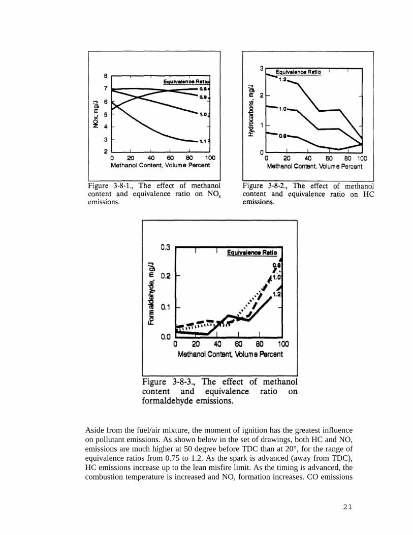
One of the issues in modern engine design is the control of specific pollutants. Increasing the percentage of methanol and lowering the equivalence ratio decreases hydrocarbon and CO emissions but increases the creation of NOx and formaldehyde, as can be seen in Figure below Lean burn strategies, while providing better thermal efficiency and lower hydrocarbon and CO emissions, produce higher NOx emissions. When the fuels are burnt in near equivalence ratio the NOx is found to be reduced.
21
Aside from the fuel/air mixture, the moment of ignition has the greatest influence on pollutant emissions. As shown below in the set of drawings, both HC and NO, emissions are much higher at 50 degree before TDC than at 20°, for the range of equivalence ratios from 0.75 to 1.2. As the spark is advanced (away from TDC), HC emissions increase up to the lean misfire limit. As the timing is advanced, the combustion temperature is increased and NO, formation increases. CO emissions

22
are almost completely independent of ignition timing and are primarily a function of the fuel/air ratio.
23
Alcohols and Gasoline Blends – Distillation Curves:
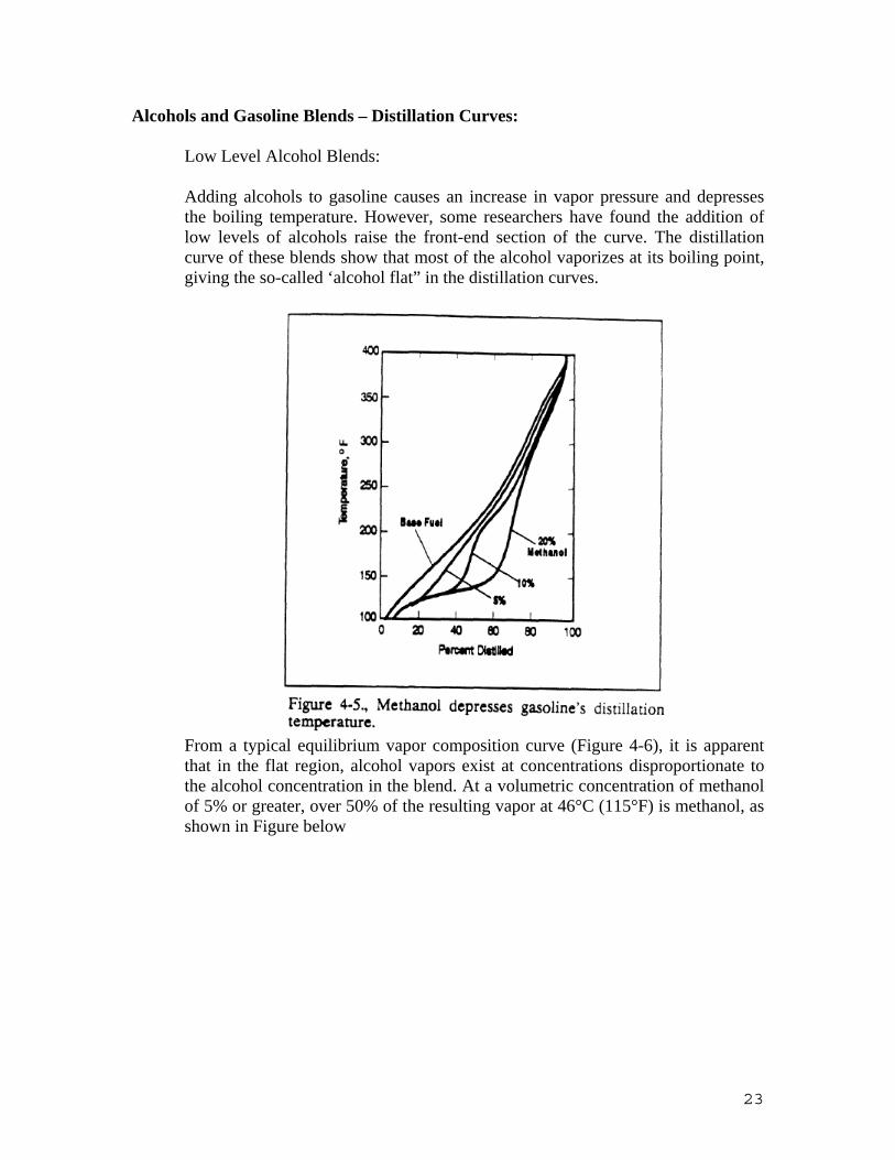
Low Level Alcohol Blends: Adding alcohols to gasoline causes an increase in vapor pressure and depresses the boiling temperature. However, some researchers have found the addition of low levels of alcohols raise the front-end section of the curve. The distillation curve of these blends show that most of the alcohol vaporizes at its boiling point, giving the so-called ‘alcohol flat” in the distillation curves.
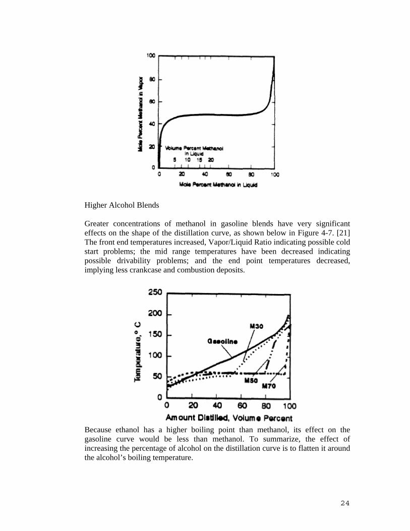
From a typical equilibrium vapor composition curve (Figure 4-6), it is apparent that in the flat region, alcohol vapors exist at concentrations disproportionate to the alcohol concentration in the blend. At a volumetric concentration of methanol of 5% or greater, over 50% of the resulting vapor at 46°C (115°F) is methanol, as shown in Figure below
24
Higher Alcohol Blends Greater concentrations of methanol in gasoline blends have very significant effects on the shape of the distillation curve, as shown below in Figure 4-7. [21] The front end temperatures increased, Vapor/Liquid Ratio indicating possible cold start problems; the mid range temperatures have been decreased indicating possible drivability problems; and the end point temperatures decreased, implying less crankcase and combustion deposits.
Because ethanol has a higher boiling point than methanol, its effect on the gasoline curve would be less than methanol. To summarize, the effect of increasing the percentage of alcohol on the distillation curve is to flatten it around the alcohol’s boiling temperature.

25
Conversion of Diesel Engines to run with Alcohol:
When diesel engines are converted to alcohols, some properties of gasoline, diesel and alcohol should be concerned. Table 5.2 shows the properties of the fuels .There are several methods for converting a diesel engine to alcohol to be discussed.
Table 5.2. Some properties of fuels
Gasoline Diesel Methanol Ethanol 1. Cetane number - 50 5 8 2. Octane number 96 - 112 107 3. Auto-ignition tempt. ° C 371 315 446 390 4. Latent heat of vaporization (KJ/Kg) 349 220 1177 914 5. Lower heating value (KJ/Kg) 4400 42600 19945 26700
a. Cetane number and cetane improving additive
For a fuel to burn in a diesel engine, it must have a high cetane number or ability to self-ignite at high temperatures and pressures. There exists a significant difference among gasoline, diesel and alcohol in terms of cetane number and auto ignition. A high cetane number leads to a short ignition delay period, whereas a low cetane number results in a long ignition delay period. From table 5.2, it can be seen that alcohols have lower cetane number than that of diesel, which is not desired when diesel engines are converted to alcohol. Fortunately, some additives, an example of which is nitrate glycol, can increase the cetane number of alcohols. This means that ignition delay period will become short, which will reduce tendency to cause a diesel knock. However, too short ignition delay period will cause a lower rate of heat release which is not wanted.
b. Alcohol-diesel emulsions
Because alcohols have limited solubility in diesel, stable emulsion must be formed that will allow it to be injected before separation occurs. Hydroshear emulsification unit can be used to produce emulsions of diesel-alcohol. However, the emulsion can only remain stable for 45 seconds. And, 12% alcohol (energy basis) is the maximum percentage. In addition, this kind of method has several problems which are as follows: 1).Specific fuel consumption at low speed increases; 2).High cost; 3).Instability. Therefore, other methods are developed.
c. Fumigation
Fumigation is a process of introducing alcohol into the diesel engine (up to 50%) by means of a carburettor in the inlet manifold. At the same time, the diesel pump

26
operates at a reduced flow. In this process, diesel fuel is used for generating a pilot flame. And, alcohol is used as a fumigated fuel. Two points should be noted in using this method. At low loads, quantity of alcohol must be reduced to prevent misfire .On the other hand, at high loads, quantity of alcohol must also be reduced to prevent pre-ignition.
d. Dual injection
In dual injection system, a small amount of diesel is injected as a pilot fuel for ignition source. And a large amount of alcohol is injected as main fuel. It must be noted that the pilot fuel must be injected prior to injection of alcohol. Some ideal results can be achieved when this method is used. Thermal efficiency is better. At the same time, NOx emission is lower. Moreover, CO emissions and HC emissions are the same. However, the system requires two fuel pumps, thus, leading to a high cost. Meanwhile, alcohol needs additives for lubricity.
e. Heated surfaces
Alcohol can ignite with hot surfaces. For this reason, glow-plugs can be utilized as a source of ignition for alcohol. In this system, specific fuel consumption depends on glow-plug positions and temperatures. It must be noted that the temperature of glow-plugs must vary with load. However, the glow-plug becomes inefficient at a high load. In addition, the specific fuel consumption is higher than that of diesel.
f. Spark-ignition
When a spark plug is used, diesel engine can be converted to Otto cycle engine. In this case, compression ratio should be reduced, from 16: 1 to 10.5: 1. There are two types about this kind of conversion. They are as follows:
Type 1: The original fuel injection system is maintained. Alcohol needs additive for lubricity (Nitride glycol). Besides, both distributor and sparkplug need to be installed, thus leading to a high cost of conversion. It is critical to adjust an ideal injection and spark-time for this kind of conversion.
Type 2: Original fuel injection is eliminated. But, a carburettor, a spark-plug and a distributor need to be installed, which increases the cost of conversion. In this conversion, spark timing is critical.
Both the type 1 and type 2 conversion have a lower thermal efficiency than that of diesel.

27
UNIT III CNG
The origin of natural gas derives from the decomposition of plants and animals over a long period of time and under tremendous heat and pressure. When natural gas comes out of the ground, it commonly mixed with water, liquefied hydrocarbons, hydrogen sulfide and other solid matter. The gas is cleaned of the water and solid matter, then the other gases and liquids are stripped away. Because water content in natural gas would cause formation of ice or hydrates in the pipeline. Likewise, the amount of available hydrocarbons heavier than ethane should be taken into account to reduce the risk of blocking the pipeline due to accumulation of condensable liquids
Natural gas is a naturally occurring mixture of combustible hydrocarbon gasses found in porous formations beneath the earth's surface, usually in association with crude petroleum. When it is found, it can be
• Nonassociated gas--Free gas not in contact with significant amounts of crude oil in the reservoir
• Associated gas--Free gas in contact with crude oil in the reservoir. • Dissolved gas--Gas in solution with crude oil in the reservoir.
The main component of natural gas is methane (CH4) with minor amounts of heavier hydrocarbons and some nonhydrocarbons,
Table 1. Natural Gas Components in mass and volume percent.
Component Volume (percent) Mass (percent)Methane 92.29 84.37Ethane 3.6 6.23Propane 0.8 2.06Butanes 0.29 0.99Pentanes 0.13 0.53Hexanes 0.08 0.39CO2 1 2.52Nitrogen 1.8 2.89Water 0.01 0.01Total 100 100
FUEL COMPONENTS
CNG is a mixture of several gases. Methane is the dominant component , but ethane and " heavier hydrocarbons" such as propane butanes, etc. are in natural gas up to a maximum of their equilibrium vapor pressure. Only saturated hydrocarbons ( alkane, in other word paraffins) are found in gas. The general formula for this series is CnH2n+2.

28
Table 3. Properties of Natural Gas Components
Component Formula Molecular Weight
Density kg/m3)
Specific Gravity
Boiling Point(C)
Autoign. Temp.(C)
Flamm. Limits
Methane CH4 16.04 0.68 0.554 -161.5 537 5-15Ethane C2H6 30.07 1.286 1.049 -88.6 515 3-12.5Propane C3H8 44.09 1.915 1.562 -42 450 2.1-9.5n-Butane C4H10 58.12 2.534 2.067 -0.5 405 1.8-8.5n-Pentane C5H12 72.11 3.05 2.487 36.1 260 1.4-7.8n-Hexane C6H14 86.17 3.642 2.97 68.7 234 1.2-7.5Nitrogen N2 28.02 1.192 0.972 Oxygen O2 32 1.355 1.105 Carbon Dioxide CO2 44.01 1.874 1.528
Paraffins are unable to combine with additional hydrogen atoms. They are also called "saturated". If the paraffin has more than three carbons, there is possibility of having more than one arrangement of the carbon and hydrogen atoms in molecule. Molecules which contain the same number and some kind of atoms, but differ in structure are called isomers. For example, three structural isomers of pentane (C5H12) are possible.
n-pentane isopentane neopentaneBoiling Point 36.1 27.9 9.5Melting Point -129.7 -159.9 -16.5Density (20 C) 0.6262 0.6201 0.6135
Alkenes (olefins) and alkynes are not normally present in natural gas. Olefins are among the most photochemically reactive components of automotive hydrocarbon emissions. Other compounds present in natural gas include: nitrogen (N2), sulfur (H2S), and odorants such as ethyl mercaptan (C2 H5 SH), carbon dioxide (CO2) and water (H2O).
The composition of natural gas has impact on emission, performance and safety. In terms of this issue, the effect of gas composition can be outlined as follows:
• Knock tendency of the fuel • Fuel stratification in the storage cylinder • Fuel metering which is primary effect on engine performance and emissions. • Corrosion occurrence due to impurities in the fuel.
Water, sulfurcompounds, carbon dioxide, oxygen and other impurities in natural gas cause storage tank and fuel system corrosion and corrosion-fatigue cracking of the materials. The limitations of this impurities are important in terms of minimizing of corrosion and acceptable service life of the storage tank. Ice occurance in regulators and lines due to condensation of water content in natural gas should be considered. Besides this, clogging in fuel injectors and fuel filters cause rough engine operation.

29
The dew point indicates the point at which gas to become saturated with water vapor. At dew point, the mixture contains maximum amount of water. Relative humidity is 100 % at this temperature. When the natural gas is compressed from pipeline pressure of approximately 50 psi to tank pressure of 3600 psi, this increase causes higher dew point which is the function of pressure. Liquid water would precipitate out of the gas with the consequence of this increase. Dryers or desiccants are used to remove the water. Another method is the methanol injection in order to decrease the freezing point of the gas. Pipeline quality natural gas has a dew point of -28 F at 50 psi which corresponds 52 F at 3600 psi. In order to prevent occurrence of corrosion problems in vehicles, natural gas must be dried to a dew point under the minimum ambient temperature in which the vehicle run. Regarding this matter the dew point of the gas at the maximum operating pressure to be at least 10 F below the winter design dry bulb temperature will be required by the proposed regulations.[4]
Fuel stratification in the cylinder should be considered when the natural gas contains heavy hydrocarbons. At low ambient temperatures, as fuel draws from the storage tank, the pressure decreases. This decrease changes the composition of liquid and vapor states. For instance, propane/air peak shaving gas is not suitable for natural gas vehicles due to the variation of propane concentration more than 10 percent during the operation. Obviously, the variation of the fuel composition has a primary impact on engine performance, knock tendency, emissions and fuel economy. In order to handle the variation of fuel composition,
• Combustion systems • Exhaust catalysts • Engine controls
can be taken into consideration for natural gas vehicles
INTERNAL ENGINE FUEL CHARACTERISTICS
OCTANE NUMBER
The high octane number of natural gas allows high compression ratio in optimized natural gas engine which means an increase in power and efficiency.
CETANE NUMBER
Cetane number is of primary importance in overall efficiency of diesel engine. CNG has a very poor cetane number . Because of this, some modifications are necessary in diesel engine for CNG applications.
HEATING VALUE
The heating value in another word, (heat of combustion, calorific value,) of a fuel is the amount of heat produced when the fuel is burned completely. A fuel with low heating value provides less heat on combustion which means less power than the same amount of fuel with high heating value. In order to maintain power output with low-heating value fuel , more consumption of it would be necessary. If natural gas is used in optimized engine, better fuel consumption will be obtained
Energy content based on volume, determines the vehicle range. To increase the range, a high density fuel is preferred because heating value per unit volume of fuel is greater. This explains
30
why the liquid state is of primary interest for storage problem. According to this data vehicle running on CNG can travel only 26 % as far as it could on gasoline.
VAPOR PRESSURE
Vapor Pressure of a fuel is a prime importance of drivebility of vehicles under all conditions. One of the most common method to measure fuel volatility is Reid Method. In this method, the vapor pressure of liquid fuel is measured at 100 F in a chamber having 4:1 air to liquid ratio. There is no need to vaporize CNG, contrarily liquid fuels have to be vaporized before they are introduced into the engine. This characteristics of CNG makes the cold start problems and low temperature emissions due to the cold enrichment, minimum.
HEAT OF VAPORIZATION
The heat of vaporization of a fuel effects the volumetric efficiency positively by decreasing the temperature of the fuel-air mixture which means makes the mixture dense. Although natural gas has a higher heat of vaporization, it is already in gaseous state when it is inducted into engine and it does not provide this cooling effect. On the other hand cold starting problems would occur with higher heat of vaporization in IC engines.
WOBBE NUMBER
Wobbe number is especially an important parameter in open loop control system. Wobbe number defines the chemical energy that will flow through an orifice with a given pressure drop. It is calculated by dividing the heating value of the fuel by the square root of specific gravity.
To describe natural gas characteristics on the basis of its energy content, Wobbe number is used. Wobbe number is computed by dividing square root of the ratio between CNG and air specific gravity ; it represents the energy flow rate resulting from a certain pressure drop. Wobbe number increases when the content of the non-methane hydrocarbon increases. This increase results from the higher densities of the non-methane hydrocarbons. The Wobbe number decreases when the inert gases concentration rises.
In an open loop engine, different Wobbe number causes change in stoichometric A/F ratio which effects equivalence ratio. Equivalence ratio is of primary importance in engine operation.In closed loop control engine, the affection of variations in Wobbe number is negligible. Because, engine control module responds the signal from the exhaust oxygen sensor and corrects for equivalence ratio change.
CONVERSION SYSTEMS
There are basically two types of conversion systems available, mechanical (carburetted) and electronic (fuel injected) types. Mechanical systems work on the same principles as gasoline carburetor do. The fuel is mixed with the intake air in a fuel/air mixture (carburetor). In electronic systems, injectors or flow control valves are used to meter the fuel into the intake air.
A) Mechanical Conversion System :
• Mixer
Gaseous fuel is introduced into intake manifold. The mixer is placed upstream of the throttle valve in order to respond to manifold pressure to provide the adequate amount of fuel introduced into
31
the manifold for engine load. Some mixers have air valve to control the air flowrate. Needle valve adjustments provide appropriate fuel / air mixture.
Air flow capacity requirement for the range of the necessary engine operation conditions is the selection criteria of mixers. The power obtained from engine is dependent of the size of mixer. The selection of small size of mixer causes the restriction of air entering to intake manifold after a certain point. Consequently engine is not be able to achive the desired operation with respect to increased throttle opening. Engine starting and low speed running will be problem with the oversize mixer due to inadequate and poorly controlled manifold vacuum. The engines which can not run with wide open throttle will probably operate with smaller size mixer. The advantage of slightly oversize mixer appears on over-the road applications. Because it achieves optimum performance at higher engine speeds. The formula which is below can be used in order to estimate required air flowrate.
• Regulator:
In order to provide necessary control in CNG conversions, pressure regulations are achived in two stages. A single regulator with two stages or two separate regulators can be used for this purpose.
In first stage, the pressure is reduced from tank pressure to approximately 100 psi. It is necessary to reduce the pressure to a few inches of water to meter the fuel through the mixer and into intake manifold. There are two kind of two stage regulators available.
The piston regulators compared to diaphram type provides better control in terms of outlet pressure with varying tank pressure. In mechanical conversion, this pressure variation is compansated by the precise control of second stage regulator with respect to varying inlet pressure. However, for an electronic conversion without second stage regulator this pressure variation is of importance in the amount of fuel that meters through the injector.
• Shut-off valve:
It stops the flow of the natural gas when the engine does not run. The valve provides fuel flow from the tank to regulator when the engine runs. A filter can be available with this equipment to filter the fuel before entering the regulator.
It is a solenoid type valve which is controlled from the fuel selector switch in the vehicle. This valve shuts off the gasoline supply when the alternative fuel is selected. It is also required to cut the power to gasoline injectors when the engine runs on alternative fuel.
• Control Valve:

32
It responds to outputs from the conversion system computer in order to provide a richer or leaner fuel / air fuel mixture. In some applications control valve operates with the second stage regulator make the fuel / air ratio leaner during deceleration. The control valve is driven by the conversion system computer in order to determine fuel / air ratio by receiving outputs from oxygen sensor which is placed in engine exhaust.
Figure 4. Oxygen Sensor
Oxygen sensor is installed into exhaust manifold. ZrO2 is coated with a platinum films on both sides. ZrO2 acts as a solid electrolyte, its output is strogly dependent of oxygen content of the exhaust gas. Small voltage is generated on the platinum surfaces due to difference between the oxygen content in atmosphere and exhaust. Measured value of the oxygen content in exhaust provides conversion system computer keep the A/F ratio within 0.05 tolerance.
• Refueling Receptacle:
The refueling receptacle should provide safe and easy using with minimum trapped gas or vapor release when disconnected. It must be a quick disconnect type. They are constructed of non-sparking material, usually brass with corrosion resistant iternal parts. NGV-1 (ANSI Standard) is available for receptacles. According to this :
• The nozzle and receptacle shall not be used for any other fuel • Standards shall be uniform throughout the U.S and Canada. • Receptacles shall be non-sparking • They should allow interchangeability between different manufacturers. • They should be designed to prevent the loading of a vehicle with a lower service
pressure • They should have a non-contact integral check valve.
Check valve leakege appear the common reason which is relaed to receptacle problems. Particulate contamination and ice or hydrate build up usually cause the problems with receptacles.
• Electronic Control Units:

33
Electronic control units with mechanical conversion systems vary from the simple type device which mainly eliminate false Electronic Control Module (ECM) malfunction codes to smart equipments with adaptive memory which dynamically control the A/F ratio and ignition.
Basic type device provides prevent false EGR, knock and oxygen sensor malfunction codes by using open loop control strategy together with the Original Equipmenr Manufacturer (OEM).
Advanced type devices evaluate data from all the engine sensors to adjust A/F ratio, spark timing and other controllable parameters by using feedback control (closed loop control) strategy.This type devices also have a feature in order to achieve open loop control method for some conditons like cold starting and wide open throttle (WOT)
B) Electronic Conversion System:
The main difference in the application of electronic conversion method with respect to mechanical conversion is the use of solenoid driven injectors or proportional metering valves to supply the fuel into intake manifold instead of fuel air mixture. Fuel injection provides significant advantages over the use of mixer. These are:
• Nonrequirement of second stage regulator. • Better emission control. • Easy starting, particularly in cold weather. • Better Brake Spesific Fuel Consumption (BSFC). • Quick throttle response. • Accurate fuel control. • Possibility of flowrate control on deceleration. • Pulse Width Modulated (PMW) control strategy
When solenoid injectors used, the amount of fuel introduced into engine can be adjusted by varying the pulse width (the period which is valve open.). In case of proportional flow control valves are used instead of solenoid injectors, the fuel flowrate is metered by using a mass flow sensor which supplies data to to the alternative fuel microprocessor which achieves the control of the valve. The Alternative Fuel Microprocessor evaluates Original Equipment Manufacturer (OEM) speed density in order to drive the alternative fuel injectors. Another approach is to modify the injector actuation signal delivered by OEM Electronic Control Module. Ignition timing is also one of the parameters controlled by alternative fuel microprocessor.
The use of injectors or flow control valve provides very accurate and precise control of mixture ratio which is resulted in optimum operation conditions at all loads. These operation conditions can not be achieved by mechanical conversion systems. Electronic systems have first stage regulator to decrease 3600 psi of tank pressure to 50-100 psi of injector pressure. However, some electronic systems equipped with flow control valve require second stage regulator.

34
Hydrogen is an energy carrier, not an energy source — it stores and delivers energy in a usable form, but it must be produced from compounds that contain it.
Hydrogen can be produced using diverse, domestic resources including fossil fuels, such as coal (with carbon sequestration) and natural gas; nuclear; and biomass and other renewable energy technologies, such as wind, solar, geothermal, and hydroelectric power.
In the future, the hydrogen economy will not rely on a single production pathway — the great potential for diversity of supply is an important reason why hydrogen is such a promising energy carrier.
Hydrogen can be produced at large central plants as far as several hundred miles from the point of end-use; semi-centrally, 25 to 100 miles from the point of end-use; or in small distributed units located at or very near the point of end-use, such as at refueling stations or stationary power sites.
How Is Hydrogen Produced? Researchers are developing a wide range of technologies to produce hydrogen economically from a variety of resources in environmentally friendly ways.
Natural Gas Reforming Hydrogen can be produced from methane in natural gas using high-temperature steam. This process, called steam methane reforming, accounts for about 95 percent of the hydrogen used today in the United States. Another method, called partial oxidation, produces hydrogen by burning methane in air. Both steam reforming and partial oxidation produce a “synthesis gas,” which is reacted with water to produce more hydrogen.
Renewable Electrolysis Electrolysis uses an electric current to split water into hydrogen and oxygen. Making hydrogen from water by electrolysis is one of the more energy-intensive ways to produce the fuel. It is a clean process as long as the electricity comes from a clean source. But electrolysis is associated with losses. Electrolysis is the reversal of the hydrogen oxidation reaction the standard potential of which is about 1.23 Volts at NPT conditions. But electrolyzers need higher voltage to separate water into hydrogen and oxygen. The over-potential is needed to overcome polarization and ohmic loss es caused by electric current flow under operational conditions. The electrolyzer and fuel cell characteristics are schematically shown in Figure 3. Under open circuit conditions the electrochemical potential is 1.23 Volts at 20°C. Assuming that the same electrolyte and catalysts are used, the polarization losses are typically 0.28 Volt for solid polymer or alkaline systems. The apparent open circuit voltages thus become 0.95 and 1.51 Volt for fuel cell and electrolyzer, respectively. For both we assume an area-specific resistance of 0.2 Wcm2 and construct the characteristics for a low temperature fuel cell (dashed line) and a corresponding electrolyzer (solid line). Fuel cells are normally operated at 0.7 Volt to optimize the system efficiency. We assume the same optimization requirements also hold for an electrolyzer. In this case the corresponding voltage of operation is 1.76 Volts as indicated by the dash-dot lines in Figure 3.

35
The standard potential of 1.23 Volts corresponds to the higher heating value HHV of hydrogen. Consequently, the over-potential is a measure of the electrical losses of the functioning electrolyzer. The losses depend on the current density or the hydrogen production rate. As shown in Figure 4, at 1.76 Volt 1.43 energy units must be supplied for every HHV energy unit contained in the liberated hydrogen. At higher hydrogen production rates (higher current densities) this number increases further. Nevertheless, electrolysis is perhaps the only practical link between physical renewable energy (kinetic energy from wind, water and waves, radiation from the sun, geothermal heat) and chemical energy needed for transportation. Also, electrolysis offers a way of virtual storage of electricity from intermittent sources.

36
Gasification Gasification is a process in which coal or biomass is converted into gaseous components by applying heat under pressure and in the presence of steam. A subsequent series of chemical reactions produces a synthesis gas, which is reacted with steam to produce more hydrogen that then can be separated and purified.
Producing hydrogen directly from coal by gasification and reforming processes is much more efficient than burning coal to make electricity that is then used to make hydrogen. Researchers are developing carbon capture and sequestration technologies to separate and store the carbon dioxide (CO2) produced in this process. With carbon capture and sequestration, hydrogen can be produced directly from coal with near-zero greenhouse gas emissions.
Like coal, biomass can be gasified using high temperatures and steam to produce hydrogen. Because biomass resources consume CO2 in the atmosphere as part of their natural growth process, producing hydrogen through biomass gasification releases near-zero net greenhouse gases.
Renewable Liquid Reforming Biomass can also be processed to make renewable liquid fuels, such as ethanol or bio-oil, that are relatively convenient to transport and can be reacted with high-temperature steam to produce hydrogen at or near the point of end-use.
Nuclear High-Temperature Electrolysis Heat from a nuclear reactor can be used to improve the efficiency of water electrolysis to produce hydrogen. By increasing the temperature of the water, less electricity is required to split it into hydrogen and oxygen, which reduces the total energy required.

37
High-Temperature Thermochemical Water-Splitting Another water-splitting method uses high temperatures generated by solar concentrators (special lenses that focus and intensify sunlight) or nuclear reactors to drive a series of chemical reactions that split water. All of the chemicals used are recycled within the process.
Photobiological and Photoelectrochemical When certain microbes, such as green algae and cyanobacteria, consume water in the presence of sunlight, they produce hydrogen as a byproduct of their natural metabolic processes. Similarly, photoelectrochemical systems produce hydrogen from water using special semiconductors and energy from sunlight.
How Is Hydrogen Delivered Today? Suppliers currently transport hydrogen by pipeline or by road using tube trailers and cryogenic liquid hydrogen tankers. For special purposes, liquefied hydrogen is transported by barge. Hydrogen also can be moved using carriers — chemical substances that incorporate atoms of hydrogen and other elements — such as ethanol or ammonia.
Pipelines are the least expensive way to deliver large volumes of hydrogen, but the current hydrogen pipeline infrastructure in the United States is very small (approximately 700 miles, compared to more than one million miles of natural gas pipelines). Hydrogen pipelines currently exist in just a few regions, near large petroleum refineries and chemical plants in Illinois, California, and the Gulf Coast.
Transporting compressed hydrogen gas over the road in high-pressure tube trailers is expensive and used primarily for short distances; it becomes cost-prohibitive when transporting farther than about 200 miles from the point of production.
Liquefied hydrogen (cooled to -423°C) is denser and has a higher energy content than gaseous hydrogen in a given volume (such as a tank), so it is preferred for delivering hydrogen over long distances, when compared to delivery by tube trailer. Liquefaction is costly and takes a great deal of energy. Nonetheless, because current pipeline transport has limited availability, hydrogen is often transported as a liquid in super-insulated, cryogenic, over-the-road tankers and then vaporized for use at the customer site.
What Are the Challenges? Hydrogen has a low volumetric energy density — it contains a relatively small amount of energy by volume compared to other fuels such as natural gas and gasoline — so its transportation, storage, and final delivery to the point of end-use are costly and result in some of the energy inefficiencies associated with using it as an energy carrier.
The high initial capital costs of new pipeline construction constitute a major barrier to expanding hydrogen pipeline delivery infrastructure. Technical concerns related to pipeline transmission include the potential for hydrogen to embrittle the steel and welds used to construct pipelines, and the need for lower cost, more reliable, and more durable hydrogen compression technology. Also, because hydrogen molecules are very small, preventing permeation and leakage from pipeline and other containment materials is a challenge.
How hydrogen is produced also affects the cost and method of delivery. Producing hydrogen in large, central plants (as far as several hundred miles from the point of end-use) results in longer transport distances that increase delivery costs. Distributed production at the point of end-use, such as refueling stations or stationary power sites, eliminates the transportation costs, but results in higher production costs.

38
Where and How Will Hydrogen be Stored? Hydrogen storage will be required onboard vehicles and at hydrogen production sites, hydrogen refueling stations, and stationary power sites. Possible approaches to storing hydrogen include:
Physical storage of compressed hydrogen gas in high pressure tanks (up to 10,000 pounds per square inch);
Physical storage of cryogenic liquid hydrogen (cooled to -253°C) in insulated tanks; and
Storage in advanced materials — within the structure or on the surface of certain materials, as well as in the form of chemical precursors that undergo a chemical reaction to release hydrogen.
What Are the Challenges? Hydrogen has a very high energy content by weight (about three times more than gasoline), but it has a very low energy content by volume (about four times less than gasoline). This makes hydrogen a challenge to store, particularly within the size and weight constraints of a vehicle.
A light-duty fuel cell vehicle must carry approximately 5-13 kilograms of hydrogen on board (depending on the size and type of the vehicle) to allow a driving range of more than 300 miles, which is generally regarded as the minimum for widespread public acceptance. Drivers must also be able to refuel at near room temperature and at a rate comparable to the rate of refueling today’s gasoline vehicles.
Using currently available storage technology, placing a sufficient quantity of hydrogen onboard a vehicle to provide a 300-mile driving range would require a very large tank — larger than the trunk of a typical automobile. Aside from the loss of cargo space, there would also be the added weight of the tank(s), which would in turn reduce fuel economy. Low-cost materials and components for hydrogen storage systems are needed, as well as low-cost, high-volume manufacturing methods for those materials and components.
Scientists in government, industry, and academia are working to improve the weight, volume, and cost of current hydrogen storage systems, as well as identify and develop new technologies that can achieve similar performance, at a similar cost, as gasoline fuel storage systems.
Compressed gas and liquid hydrogen tanks Current compressed hydrogen gas tanks are much larger and heavier than what is ultimately
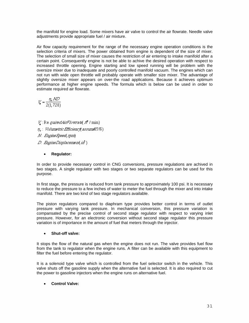
desired for light-duty vehicles. Researchers are evaluating light-weight, safe, composite materials that can reduce the weight and volume of compressed gas storage systems. Energy is needed to compress gases. The compression work depends on the thermodynamic compression process. The ideal isothermal compression cannot be realized The energy consumed by an adiabatic compression of monatomic Helium, diatomic hydrogen and five-atomic methane from atmospheric conditions (1 bar = 100,000 Pa) to higher pressures is shown in Figure 2. Clearly, much more energy per kg is required to compress hydrogen than methane.
39
Liquefied hydrogen is denser and has a higher energy content than gaseous hydrogen in a given volume. Liquid hydrogen tanks can store more hydrogen than compressed gas tanks, but it takes energy to liquefy hydrogen, and the tank insulation required (to prevent hydrogen loss) also affects the weight and volume of hydrogen that can be stored. Researchers are studying a hybrid tank concept that can store high-pressure hydrogen gas under cryogenic conditions (cooled to around -120 to -196°C) — these “cryo-compressed” tanks would allow relatively lighter weight, more compact storage.
Even more energy is needed to compact hydrogen by liquefaction. Theoretically only about 3.6 MJ/kg have to be removed to cool hydrogen down to 20K (-253°C) and another 0.46 MJ/kg to condense the gas under atmospheric pressure. About 4 MJ/kg are removed from room temperature hydrogen gas in the process, little compared to its energy content of 142 MJ/kg. But cryogenic re frigeration is a complex process involving Carnot cycles and physical effects (e.g. Joule- Thomsen) that do not obey the laws of heat engines. Nevertheless, the Carnot efficiency is used as a reference for the foregoing process analysis. For the refrigeration between room temperature (TR = 25°C = 298 K) and liquid hydrogen temperature (TL = -253°C = 20 K) one obtains a Carnot efficiency of �c = T L / (TR – TL) = 20 K / (298 K -20 K) = 0.072 or about 7%. The assumed single-step Carnot-type cooling process would consume at least 57 MJ/kg or 40% of the HHV energy content of hydrogen. This simple analysis does not include mechanical, thermal, flow-related or electrical losses in the multi-stage refrigeration process. But by intelligent process design the Carnot limitations may be partially removed. But the lower limit of energy consumption of a liquefaction plant does not drop much below 30% of the higher heating value of the liquefied hydrogen. As a theoretical analysis of the complicated, multi-stage liquefaction processes is difficult, we present the energy consumption of existing hydrogen liquefaction plants

40
The compilation reveals the following. Small (10 kg/h) liquefaction plants need about 100 MJ/kg, while large plants of 1000 kg/h or more capacity consume about 40 MJ of electrical energy for each kg liquefied hydrogen. The actual liquefaction energy consumption for plants between 1 to 10,000 kg/h capacity is shown in Figure 7. The specific energy input decreases with plant size, but a minimum of about 40 MJ per kg H2 remains. In Figure 8 the required energy input is compared to the higher heating va lue HHV of hydrogen. For small liquefaction plants the energy needed to liquefy hydrogen may exceed the HHV of the gas. But even with the largest plants (10,000 kg/h) at least 30% of the HHV energy is needed for the liquefaction process.
Gasoline tanks used in cars and trucks today are considered conformable and take maximum advantage of available vehicle space. Researchers are evaluating concepts for conformable high-pressure hydrogen tanks as an alternative to cylindrical tanks, which do not package well in a vehicle.
Materials-based storage Hydrogen atoms or molecules bound tightly with other elements in a compound (or potential storage material) may make it possible to store larger quantities of hydrogen in smaller volumes at low pressure and near room temperature.
Scientists are investigating several different kinds of materials, including metal hydrides, carbon-based materials, and chemical hydrides, as well as identifying new materials with potential for storing hydrogen.
Hydrogen storage in materials offers great promise, but additional research is required to better understand the mechanism of hydrogen storage in materials under practical operating conditions and to overcome critical challenges related to capacity, the uptake and release of hydrogen, management of heat during refueling, cost, and life cycle impacts.

41
The Facts of Hydrogen Safety As the lightest and smallest element in the universe, confining hydrogen is very difficult. Hydrogen is much lighter than air and rises at a speed of almost 20 meters per second — two times faster than helium and six times faster than natural gas — which means that when released, it rises and dilutes quickly.
Combustion cannot occur in a tank or any contained location that contains only hydrogen. An oxidizer, such as oxygen, must be present.
Hydrogen is odorless, colorless, and tasteless and therefore undetectable by human senses. For these and other reasons, industry uses hydrogen sensors to detect hydrogen leaks. Natural gas is also odorless, colorless, and tasteless, but industry adds a sulfur-containing odorant so people can detect it. These odorants cannot be used with hydrogen, however, because they contaminate fuel cells, a popular hydrogen application.
Hydrogen burns very quickly. Under optimal combustion conditions, the energy required to initiate hydrogen combustion is significantly lower than that required for other common fuels, such as natural gas or gasoline. At low concentrations of hydrogen fuel in air, the energy required to initiate combustion is similar to that of other fuels.
Hydrogen flames have low radiant heat. A hydrogen fire has significantly less radiant heat when compared to a hydrocarbon fire. Since low levels of heat are emitted near a hydrogen flame (the flame itself is just as hot), the risk of secondary fires is lower.
With the exception of oxygen, any gas can cause asphyxiation in high enough concentrations. In most scenarios, however, because hydrogen rises and diffuses so rapidly, it is unlikely to be confined where asphyxiation might otherwise occur.
Hydrogen is non-toxic and non-poisonous. It will not contaminate groundwater (it’s a gas under normal atmospheric conditions), and a release of hydrogen is not known to contribute to atmospheric pollution or water pollution.

42
UNIT IV VEGETABLE OILS & BIODIESEL Vegetable oils and their derivatives (especially methyl esters), commonly referred to as “biodiesel,” are prominent candidates as alternative diesel fuels. They have advanced from being purely experimental fuels to initial stages of commercialization. They are technically competitive with or offer technical advantages compared to conventional diesel fuel. Besides being a renewable and domestic resource, biodiesel reduces most emissions while engine performance and fuel economy are nearly identical compared to conventional fuels. Several problems, however, remain, which include economics, combustion, some emissions, lube oil contamination, and low-temperature properties.
Numerous different vegetable oils have been tested as biodiesel. Often the vegetable oils investigated for their suitability as biodiesel are those which occur abundantly in the country of testing. Therefore, soybean oil is of primary interest as biodiesel source in the United States while many European countries are concerned with rapeseed oil, and countries with tropical climate prefer to utilize coconut oil or palm oil. Other vegetable oils, including sunflower, safflower, etc., have also been investigated. Furthermore, other sources of biodiesel studied include animal fats and used or waste cooking oils. Sources of biodiesel with some emphasis on developing countries have been discussed Several problems, however, have impaired the widespread use of biodiesel. They are related to the economics and properties of biodiesel. For example, neat vegetable oils reported to cause engine deposits. Attempting to solve these problems by using methyl esters causes operational problems at low temperatures. Furthermore, problems related to combustion and emissions remain to be solved. The problems associated with the use of biodiesel are thus very complex and no satisfactory solution has yet been achieved despite the efforts of many researchers around the world. Vegetable oils.
Most vegetable oils are triglycerides (TGs; triglyceride = TG). Chemically, TGs are the triacylglyceryl esters of various fatty acids with glycerol (Figure 1).
Some physical properties of the most common fatty acids occurring in vegetable oils and animal fats as well as their methyl esters are listed in Table I. Besides these fatty acids, numerous other fatty acids occur in vegetable oils and animal fats, but their abundance usually is considerably lower. Table II lists the fatty acid composition of some vegetable oils and animal fats that have been studied as sources of biodiesel.
CH2OOR CH2OH & & CHOOR + 3 CH3OH ∅ 3 CH3OOCR + CHOH & & CH2OOR CH2OH

43
Triglyceride Methanol Methyl ester Glycerol
Figure 1. Structure of triglycerides and principle of the transesterification reaction (shown for methyl esters; R = (CH2)xCH3 or unsaturated rests according to the fatty acids listed in Table I).
The most common derivatives of TGs (or fatty acids) for fuels are methyl esters. These are formed by transesterification of the TG with methanol in presence of usually a basic catalyst to give the methyl ester and glycerol (see Figure 1). Other alcohols have been used to generate esters, for example, the ethyl, propyl, and butyl esters.
Selected physical properties of vegetable oils and fats as they relate to their use as DF are listed in Table III. For esters these properties are given in Table IV. Also listed in Table III are the ranges of iodine values (centigrams iodine absorbed per gram of sample) of these oils and fats. The higher the iodine value, the more unsaturation is present in the fat or oil.
That vegetable oils and their derivatives are suited as DF is shown by their CNs (Table III) which generally are in the range suitable for or close to that of DF. The heat Table I. Selected properties of some common fatty acids and esters.
Trivial (Systematic)namea; Acronymb)
Mol. wt.
m.p.c ( C)
b.p.c,d ( C)
Cetane No.
Heat of Combustione (kg-cal/mole)
Caprylic acid (Octanoic acid); 8:0
144.22 16.5 239.3
Capric acid (Decanoic acid); 10:0
172.27 31.5 270 47.6 (98.0)f
1453.07 (25 ),
Lauric acid (Dodecanoic acid); 12:0
200.32 44 1311 1763.25 (25 ),
Myristic acid (Tetradecanoic acid); 14:0
228.38 58 250.5100 2073.91 (25 ),
Palmitic acid (Hexadecanoic acid); 16:0
256.43 63 350 2384.76 (25 ),
Stearic acid (Octadecanoic acid); 18:0
284.48 71 360d 2696.12 (25 ),
Oleic acid (9Z-Octadecenoic acid); 18:1
282.47 16 286100 2657.4 (25 ),
Linoleic acid (9Z,12Z- Octadecadienoic acid); 18:2
280.45 -5 229-3016
Linolenic acid (9Z,12Z,15Z-Octadecatrienoic acid); 18:3
278.44 -11 230-217

44
Erucic acid (13Z-Docosenoic acid); 22:1
338.58 33-4 26515
Methyl caprylate (Methyl octanoate); 8:0
158.24 ... 193 33.6 (98.6)f
1313
Methyl caprate (Methyl decanoate); 10:0
186.30 ... 224 47.7 (98.0)f
1625
Methyl laurate (Methyl dodecanoate); 12:0
214.35 5 266766 61.4 (99.1)f
1940
Methyl myristate (Methyl tetradecanoate); 14:0
242.41 18.5 295751 66.2 (96.5)f
2254
Methyl palmitate (methyl hexadecanoate); 16:0
270.46 30.5 415-8747 74.5 (93.6)f
2550
Methyl stearate (Methyl octadecanoate); 18:0
298.51 39.1 442-3747 86.9 (92.1)f
2859
Methyl oleate (Methyl 9Z- octadecenoate); 18:1
296.49 -20 218.520 47.2g 2828
Methyl linoleate (Methyl 9Z, 12Z-octadecadienoate); 18:2
294.48 -35 21520 28.5g 2794
Methyl linolenate (Methyl 9Z, 12Z,15Z-octadecatrienoate); 18:3
292.46 -57 -52
1090.018 20.6g 2750
Methyl erucate (Methyl 13Z- docosenoate); 22:1
352.60 ... 221-2225 76.0 3454
a) Z denotes cis configuration. b) The numbers denote the number of carbons and double bonds. For example, in oleic acid, 18:1 stands for eighteen carbons and one double bond. c) Melting points and boiling points given in Ref. 28, pp. C-42 to C-553. Melting points and boiling points of 12:0 - 18:0 and 18:3 esters given in Ref. 181. d) Superscripts in boiling point column denote pressure (mm Hg) at which the boiling point was determined. e) See Ref. 27. f) Cetane number from Ref. 21. Number in parentheses indicates purity (%) of the material used for CN determinations as given by the author. Other CNs given in Ref. 21 not tabulated here (purities in parentheses): ethyl caprate (10:0) 51.2 (99.4); ethyl myristate (14:0) 66.9 (99.3); propyl caprate (10:0) 52.9 (98.0); isopropyl caprate (10:0) 46.6 (97.7); butyl caprylate (8:0) 39.6 (98.7); butyl caprate (10:0) 54.6 (98.6); butyl myristate (14:0) 69.4 (99.0). g) CN from Ref. 17. CNs (lipid combustion quality numbers) deviating from Ref. 21 as given in Ref. 17: Methyl laurate 54, methyl myristate 72, methyl palmitate 91, methyl stearate 159.

45
contents of various vegetable oils (Table III) are also nearly 90% that of DF2 (11-13). The heats of combustion of fatty esters and triglycerides as well as fatty alcohols (15) have been determined and shown to be within the same range. The suitability of fats and oils as DF results from their molecular structure and high energy content. Long-chain, saturated, unbranched hydrocarbons are especially suitable for conventional DF as shown by the CN scale. The long, unbranched hydrocarbon chains in fatty acids meet this requirement. Saturated fatty compounds have higher CNs. Other observations are (i) that (a) double bond(s) decrease(s) quality (therefore, the number of double bonds should be small rather than large, (ii) that a double bond, if present, should be positioned near the end of the molecule, and (iii) no aromatic compounds should be present
Table II. Major fatty acids (in wt.-%) of some oils and fats used or tested as alternative diesel fuels.a All values combined from Refs. 176 and 181.
Oil or Fat
F a t t y A c i d C o m p o s i t i o n (Wt.-%)
12:0
14:0 16:0 18:0 18:1 18:2
18:3
22:1
Babassu
44-45
15-17 5.8-9 2.5-5.5 12-16 1.4-3
Canola
4-5 1-2 55-63 20-31
9-10
1-2
Coconut
44-51
13-18.5 7.5-10.5 1-3 5-8.2 1.0-2.6
Corn
7-13 2.5-3 30.5-43 39-52
1
Cottonseed
0.8-1.5 22-24 2.6-5 19 50-52.5
Linseed
6 3.2-4 13-37 5-23
26-60
Olive
1.3 7-18.3 1.4-3.3 55.5-84.5 4-19
Palm
0.6-2.4 32-46.3 4-6.3 37-53 6-12
Peanut
0.5 6-12.5 2.5-6 37-61 13-41
1
Rapeseed
1.5 1-4.7 1-3.5 13-38 9.5-22
1-10
40-64
Safflower
6.4-7.0 2.4-29 9.7-13.8 75.3-80.5
Safflower, high-oleic
4-8 2.3-8 73.6-79 11-19
Sesame
7.2-9.2 5.8-7.7 35-46 35-48

46
Soybean
2.3-11 2.4-6 22-30.8 49-53
2-10.5
Sunflower
3.5-6.5 1.3-5.6 14-43 44-68.7
Tallow (beef)
3-6 25-37 14-29 26-50 1-2.5
a) These oils and fats may contain small amounts of other fatty acids not listed here. For example, peanut oil contains 1.2% 20:0, 2.5 22:0, and 1.3% 24:0 fatty acids (181). Table III. Fuel-related properties and iodine values of various fats and oils.a
Oil or Fat
Iodine Value
CN HG
(kJ/kg) Viscosity (mm2/s)
CP ( C)
PP ( C)
FP
( C) Babassu
10-18
38
Castor
82-88
? 39500 297 (38 ) --- -31.7
260
Coconut
6-12
Corn
103-140
37.6 39500 34.9 (38 ) -1.1 -40.0
277
Cottonseed
90-119
41.8 39468 33.5 (38 ) 1.7 -15.0
234
Crambe
93
44.6 40482 53.6 (38 ) 10.0 -12.2
274
Linseed
168-204
34.6 39307 27.2 (38 ) 1.7 -15.0
241
Olive
75-94
Palm
35-61
42
Peanut
80-106
41.8 39782 39.6 (38 ) 12.8 -6.7
271
Rapeseed
94-120
37.6 39709 37.0 (38 ) -3.9 -31.7
246
Safflower
126-152
41.3 39519 31.3 (38 ) 18.3 -6.7
260
High-oleic safflower
90-100
49.1 39516 41.2 (38 ) -12.2 -20.6
293
Sesame
104-120
40.2 39349 35.5 (38 ) -3.9 -9.4
260
Soybean
117-143
37.9 39623 32.6 (38 ) -3.9 -12.2
254
Sunflower
110-143
37.1 39575 37.1 (38 ) 7.2 -15.0
274

47
Tallow
35-48
- 40054 51.15
(40 ) - -
201
No. 2 DF
47 45343 2.7 (38 ) -15.0 -33.0
52
a) Iodine values combined from Refs. 176 and 181. Fuel properties from Ref. 11. All tallow values from Ref. 177 (No CN given in Ref. 177, calcd. cetane index 40.15).
Table IV. Fuel-related physical properties of esters of oils and fats.a
Ester
CN
HG
(kJ/kg) Viscosity (mm2/s)
CP ( C)
PP ( C)
FPb ( C)
Methyl
Cottonseedc
51.2
- 6.8 (21 ) - -4
110
Rapeseedd
54.4
40449 6.7 (40 ) -2 -9
84
Safflowere
49.8
40060 - - -6
180
Soybeanf
46.2
39800 4.08 (40 ) 2 -1
171
Sunflowerg
46.6
39800 4.22 (40 ) 0 -4
-
Tallowh
-
39949 4.11 (40 ) 12 9
96
Ethyl
Palmi
56.2
39070 4.5 (37.8 ) 8 6
19
Soybeanf
48.2
40000 4.41 (40 ) 1 -4
174
Tallowj
15 12
Propyl
Tallowj
17 12
Isopropyl
Soybean
52.6k
-9l -12l
Tallowj
8 0
n-Butyl

48
Soybeanf
51.7
40700 5.24 (40 ) -3 -7
185
Tallowj
13 9
2-Butyl
Soybeanl
-12 -15
Tallowj
9 0
a) CN = cetane number; CP = cloud point, PP = pour point, FP = flash point.
b) Some flash points are very low. Problems with Neat Vegetable Oil Fuel. The major problems that are faced when the engines are run with Straight vegetable oils are:
• Engine deposits caused due to the deposition of carbonaceous particles and vegetable oil residues.
• Improper injection of fuels due to the higher viscosity of the oil. The nozzle may not provide fine mist of fuel particles and also built ups on injector are found which result in the bad spray pattern of fuel.
• More effort is required to pull the oil can cause damage to fuel pump and cause extra stress on timing belt
These problems can be overcome by following any of the four methods: Dilution of vegetable oils with conventional diesel fuel
Dilution is an additional possible solution to the viscosity problem of vegetable oils as discussed above. Results with this technology have been mixed and engine problems similar to those found with neat vegetable oils as fuels were observed here also. A model on vegetable oil atomization showed that blends of DF2 with vegetable oil should contain from 0 to 34% vegetable oil if proper atomization was to be achieved
Microemulsification:
The formation of microemulsions (co-solvency) is one of the four potential solutions for solving the problem of vegetable oil viscosity. Microemulsions are defined as transparent, thermodynamically stable colloidal dispersions in which the diameter of the dispersed-phase particles is less than one-fourth the wavelength of visible light. Microemulsion-based fuels are sometimes also termed “hybrid fuels,” although blends of conventional diesel fuel with vegetable oils have also been called hybrid fuels (128). Some of these fuels were tested in engines including the 200 hr EMA test. A

49
microemulsion fuel containing soybean oil, methanol, 2-octanol, and a cetane enhancer was the cheapest vegetable oil-based alternative diesel fuel ever to pass the EMA test.
The components of microemulsions can be conventional DF, vegetable oil, an alcohol, a surfactant, and a cetane improver. Water (from aqueous ethanol) may also be present in order to use lower-proof ethanol (129), thus increasing water tolerance of the microemulsions is important. Pyrolysis: Pyrolysis is the method of subjecting the oil to high pressure distillation there by reducing the viscosity of the vegetable oils. Transesterification: Transesterification is the process of converting Triglycerides in to esters by mixing with alcohols in the presence of a catalyst. The conversion of component TGs to simple alkyl esters (transesterification) with various alcohols reduces the high viscosity of oils and fats. Transesterification general procedure :
The experimental setup is shown in figure 1. A 2000 ml three-necked round-bottomed flask was used as a reactor. The flask was placed in a water bath, whose temperature could be controlled within + 2 oC. One of the two side necks was equipped with a condenser and the other was used as a thermowell. A thermometer was placed in the thermowell containing little glycerol for temperature measurement inside the reactor. A blade stirrer was passed through the central neck, which was connected to a motor alongwith speed regulator for adjusting and controlling the stirrer speed. Esterification: A known amount of karanja oil was taken in the above-mentioned setup. Required amount of sulphuric acid and methanol were added to the oil and stirred continuously maintaining a steady temperature of 640C. Intermittently samples were collected at regular intervals (30min) and acid value was determined. After the confirmation of complete reduction of acid valve to less than 1.0, the heating was stopped and the products were cooled. The unreacted methanol was separated by separating funnel. The remaining product was analyzed for acid value and it was found that the acid value varied from 1.0 to 0.5. This oil sample was for transesterified to obtain methyl esters. Transesterification: In the same setup, known amount of esterified karanja oil was charged. Required amount of catalyst NaOH was desolved in methanol and the rest amount of methanol alongwith the catalyst solution was added to the oil sample. After proper closing of the flask it was put on the water bath.The system was maintained airtight to prevent the loss of alcohol. The reaction mix was maitained at temperature just above the boiling point of the alcohol i.e. around 70°C to speed up the reaction rate.
50
Excess alcohol was used to ensure total conversion of the oil to its esters. The formation of methyl ester was monitered by using thin layer chromatography(TLC) technique. Coated silicagel glass plates were spotted with karanja oil and the sample of ester. The spotted samples were developed in solvent system in glass chamber using solvent ratio of 80:20 hexane/ether by volume. This confirms the formation of methyl esters. This procedure was followed for all the samples collected at regular interval of time to check the formation of methyl ester. After the confirmation of completion of methyl ester formation, the heating was stopped and the products were cooled and transferred to a separating funnel. Where the ester layer containing mainly methyl ester and methanol and glycerol layer containing mainly glycerol and methanol were separated. The pH level of both layers were measured and neutralised seperately. For neutralisation a known amount of sulfuric acid in methanol was added to both the layers seperately to neutralize the sodium methoxide present in them. The traces of methanol present in ester layer was recovered in a distillation column under control vacuum. Distilled methanol was weighed and stored in sample bottle. Similar procedure was adopted to recover the traces of methanol present in glycerol layer. The methyl ester was washed and dried under vacuum to remove traces of moisture. A sample of esters were analyzed for acid value.

51
Types of Transesterification process:
In the transesterification of vegetable oils, a triglyceride reacts with an alcohol in the presence of a strong acid or base, producing a mixture of fatty acids alkyl esters and glycerol25,26 (Scheme 4). The overall process is a sequence of three consecutive and reversible reactions, in which di- and monoglycerides are formed as intermediates26. The stoichiometric reaction requires 1 mol of a triglyceride and 3 mol of the alcohol. However, an excess of the alcohol is used to increase the yields of the alkyl esters and to allow its phase separation from the glycerol formed.
Several aspects, including the type of catalyst (alkaline or acid), alcohol/vegetable oil molar ratio, temperature, purity of the reactants (mainly water content) and free fatty acid content have an influence on the course of the transesterification and will be discussed below, based on the type of catalyst used.
Acid-Catalyzed Processes
The transesterification process is catalyzed by BrØnsted acids, preferably by sulfonic27 and sulfuric acids26,28,29. These catalysts give very high yields in alkyl esters, but the reactions are slow, requiring, tipically, temperatures above 100 °C and more than 3 h to reach complete conversion30. Pryde et al.26 showed that the methanolysis of soybean oil, in the presence of 1 mol% of H2SO4, with an alcohol/oil molar ratio of 30:1 at 65 °C, takes 50 h to reach complete conversion of the vegetable oil (> 99%), while the butanolysis (at 117 °C) and ethanolysis (at 78 °C), using the same quantities of catalyst and alcohol, take 3 and 18 h, respectively.
The alcohol/vegetable oil molar ratio is one of the main factors that influences the transesterification. An excess of the alcohol favors the formation of the products. On the other hand, an excessive amount of alcohol makes the recovery of the glycerol difficult, so that the ideal alcohol/oil ratio has to be established empirically, considering each individual process.
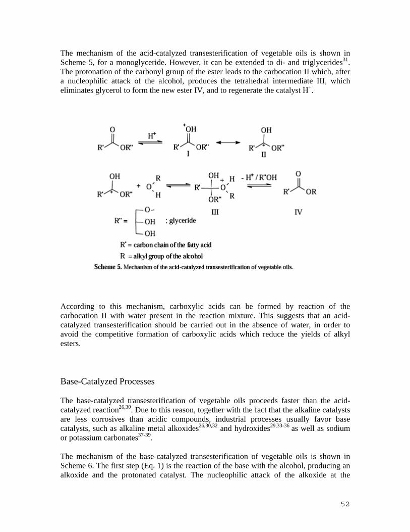
52
The mechanism of the acid-catalyzed transesterification of vegetable oils is shown in Scheme 5, for a monoglyceride. However, it can be extended to di- and triglycerides31. The protonation of the carbonyl group of the ester leads to the carbocation II which, after a nucleophilic attack of the alcohol, produces the tetrahedral intermediate III, which eliminates glycerol to form the new ester IV, and to regenerate the catalyst H+.
According to this mechanism, carboxylic acids can be formed by reaction of the carbocation II with water present in the reaction mixture. This suggests that an acid-catalyzed transesterification should be carried out in the absence of water, in order to avoid the competitive formation of carboxylic acids which reduce the yields of alkyl esters.
Base-Catalyzed Processes
The base-catalyzed transesterification of vegetable oils proceeds faster than the acid-catalyzed reaction26,30. Due to this reason, together with the fact that the alkaline catalysts are less corrosives than acidic compounds, industrial processes usually favor base catalysts, such as alkaline metal alkoxides26,30,32 and hydroxides29,33-36 as well as sodium or potassium carbonates37-39.
The mechanism of the base-catalyzed transesterification of vegetable oils is shown in Scheme 6. The first step (Eq. 1) is the reaction of the base with the alcohol, producing an alkoxide and the protonated catalyst. The nucleophilic attack of the alkoxide at the
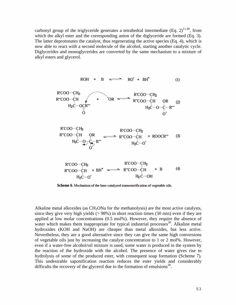
53
carbonyl group of the triglyceride generates a tetrahedral intermediate (Eq. 2)11,40, from which the alkyl ester and the corresponding anion of the diglyceride are formed (Eq. 3). The latter deprotonates the catalyst, thus regenerating the active species (Eq. 4), which is now able to react with a second molecule of the alcohol, starting another catalytic cycle. Diglycerides and monoglycerides are converted by the same mechanism to a mixture of alkyl esters and glycerol.
Alkaline metal alkoxides (as CH3ONa for the methanolysis) are the most active catalysts, since they give very high yields (> 98%) in short reaction times (30 min) even if they are applied at low molar concentrations (0.5 mol%). However, they require the absence of water which makes them inappropriate for typical industrial processes30. Alkaline metal hydroxides (KOH and NaOH) are cheaper than metal alkoxides, but less active. Nevertheless, they are a good alternative since they can give the same high conversions of vegetable oils just by increasing the catalyst concentration to 1 or 2 mol%. However, even if a water-free alcohol/oil mixture is used, some water is produced in the system by the reaction of the hydroxide with the alcohol. The presence of water gives rise to hydrolysis of some of the produced ester, with consequent soap formation (Scheme 7). This undesirable saponification reaction reduces the ester yields and considerably difficults the recovery of the glycerol due to the formation of emulsions30.

54
Lipase-Catalyzed Processes
Due to their ready availability and the ease with which they can be handled, hydrolytic enzymes have been widely applied in organic synthesis. They do not require any coenzymes, are reasonably stable, and often tolerate organic solvents. Their potential for regioselective and especially for enantioselective synthesis makes them valuable tools41.
Although the enzyme-catalyzed transesterification processes are not yet commercially developed, new results have been reported in recent articles and patents42-48. The common aspects of these studies consist in optimizing the reaction conditions (solvent, temperature, pH, type of microorganism which generates the enzyme, etc) in order to establish suitable characteristics for an industrial application. However, the reaction yields as well as the reaction times are still unfavorable compared to the base-catalyzed reaction systems.
Factors Affecting Transesterification:
Effect of Moisture and free fatty acids
The starting materials used for alkali-catalyzed Transesterification of glycerides must meet certain specifications. The glyceride should have an acid value less than 1 and all materials should be substantially anhydrous. If the acid value was greater than 1, more NaOH was required to neutralize the free fatty acids. Water also caused soap formation, which consumed the catalyst and reduced catalyst efficiency. The resulting soaps caused an increase in viscosity, formation of gels and made the separation of glycerol difficult. The e€ects of free fatty acids and water on Transesterification of beef tallow with methanol were investigated. The results showed that the water content of beef tallow should be kept below 0.06% w/w and free fatty acid content of beef tallow should

55
be kept below 0.5%, w/w in order to get the best conversion. Water content was a more critical variable in the transesterification process than were free fatty acids. The effect of molar ratio One of the most important variables affecting the yield of ester is the molar ratio of alcohol to triglyceride. The stoichiometric ratio for transesterification requires three moles of alcohol and one mole of glyceride to yield three moles of fatty acid ester and one mole of glycerol. The molar ratio is associated with the type of catalyst used. An acid catalyzed reaction needed a 30:1 ratio of BuOH to soybean oil, while a alkali-catalyzed reaction required only a 6:1 ratio to achieve the same ester yield for a given reaction time The effect of catalyst Catalysts are classified as alkali, acid, or enzyme. Alkali-catalyzed transesterification is much faster than acid-catalyzed (Freedman et al., 1984). However if a glyceride has a higher free fatty acid content and more water, acid-catalyzed transesterification is suitable. The acids could be sulfuric acid, phosphoric acid, hydrochloric acid or organic sulfonic acid. Alkalis include sodium hydroxide, sodium methoxide, potassium hydroxide, potassium methoxide, sodium amide, sodium hydride, potassium amide and potassium hydride. Sodium methoxide was more effective than sodium hydroxide because of the assumption that a small amount of water was produced upon mixing NaOH and MeOH. The effect of reaction time The conversion rate increases with reaction time. Transesterified peanut, cottonseed, sun¯ower and soybean oils under the condition of methanol to oil ratio of 6:1, 0.5% sodium methoxide catalyst and 60°C. An approximate yield of 80% was observed after 1 min for soybean and sun¯ower oils. After 1 h, the conversions were almost the same for all four oils (93±98%). Ma et al. (1998a) studied the effect of reaction time on transesterification of beef tallow with methanol. The reaction was very slow during the first minute due to the mixing and dispersion of methanol into beef tallow. From one to five min, the reaction proceeded very fast. The apparent yield of beef tallow methyl esters surged from 1 to 38. The production of beef tallow slowed down and reached the maximum value at about 15 min. The di- and monoglycerides increased at the beginning and then decreased. At the end, the amount of monoglycerides was higher than that of diglycerides. The effect of reaction temperature Transesterification can occur at different temperatures, depending on the oil used. In methanolysis of castor oil to methyl ricinoleate, the reaction proceeded most satisfactorily at 20±35°C with a molar ratio of 6:1± 12:1 and 0.005±0.35% (by weight of oil) of NaOH catalyst (Smith, 1949). For the transesteri®cation of re®ned soybean oil with methanol (6:1) using 1% NaOH, three di€erent temperatures were used. After 0.1 h, ester yields were 94, 87 and 64% for 60, 45 and 32°C, respectively. After 1 h, ester formation was

56
identical for the 60 and 45°C runs and only slightly lower for the 32°C run. Temperature clearly influenced the reaction rate and yield of esters.
Effect of mixing intensity:
It is found that the reaction is not started without mixing of the oil and alcohols. The oil or flats are immiscible with NaOH & Methanol solution. For better yield constant mixing is required.

57
UNIT V
Electric drive vehicles:
Electric drive vehicles (EDVs) are one way of reducing vehicle emissions that contribute two-thirds of all air pollution in most cities. Some electric drive technologies are battery electric vehicles (BEV), hybrid electric vehicles (HEV) and fuel cell powered vehicles (FCV).
Electric Drive Technologies Battery Electric Vehicle (BEV)
An electric vehicle is a motor vehicle, such as an automobile, truck, or bus, which uses a rechargeable battery for fuel, replacing gasoline, diesel or other types of combustible fuels. Gone are the internal combustion engine and the transmission. A BEV utilizes an electric motor or, in some applications, more than one motor to propel the vehicle.
The energy stored in the Electric Vehicle's rechargeable battery supplies power to a motor controller. The motor controller is a device that controls the amount of power supplied to the electric drive motor(s) based on the position of the accelerator pedal.
Refueling an electric vehicle consists of connecting the vehicle to an outlet or charging device that is specifically designed for charging a BEV. Recharging time varies, depending on the battery type, capacity and the voltage/current output of the charger. Most BEVs can be fully recharged in about 6 hours.
Additionally, electric vehicles are much more energy efficient then Internal Combustion Engine vehicles. Not only is the propulsion system itself much more efficient, but energy loses through the transmission and idling simply do not exist.
Hybrid Electric Vehicles (HEV)
The use of two different energy sources is what defines a hybrid vehicle. Essentially an HEV is an electric vehicle that uses an onboard internal combustion engine linked to a motor/generator to drive the vehicle and/or recharge the batteries. There are currently many different hybrid-electric system designs utilizing gasoline and diesel engines, alternative fuels engines, gas turbines or fuel cells in conjunction with batteries. These design options are grouped in three categories: series (range-extending HEVs), parallel (power assist HEVs), and dual-mode HEVs.
The main sources of energy used in the most common HEVs today are gasoline and batteries. A battery contains no moving parts. The only energy wasted is a

58
very small amount of heat during the course of a discharge cycle. As previously mentioned, hybrid electric vehicles utilize two different energy sources. For those vehicles currently available commercially, batteries are the secondary energy supplier for the vehicle and an engine that burns gasoline, diesel fuel, or alternative fuels such as methanol, ethanol or compressed natural gas provides the primary power. The cleanest, most fuel efficient HEV design is one in which there is a significant all-electric range (20 miles or more) and where the vehicle is plugged in to recharge the batteries at the end of the day. The ultimate goal of the hybrid electric vehicle is to provide the equivalent power, range, cost and safety of a conventional vehicle while reducing fuel costs and harmful emissions. At present an HEV is able to operate nearly twice as efficiently as traditional internal combustion vehicles.
Fuel Cell Vehicles (FCV)
A fuel cell vehicle is essentially an electric vehicle that has a fuel cell providing the electric energy needed to run instead of batteries. The fuel cell vehicle carries a supply of hydrogen that the fuel cell converts to electricity.
A fuel cell is an electrochemical device in which the energy of a chemical reaction is converted directly into electricity. By combining hydrogen fuel with oxygen from air, electricity is formed, without combustion of any form. Water and heat are the only by-products when hydrogen is used as the fuel source.
Although hydrogen is considered the primary fuel source for fuel cells, the process of fuel reforming allows for the extraction of hydrogen from other fuels including methanol, natural gas, petroleum, or renewable sources. Unlike a battery, a fuel cell does not run down or require recharging; it operates as long as a fuel is supplied.
Environmental Benefits
Though conventional gasoline vehicles are becoming cleaner and other alternative fuel vehicles can alleviate air pollution, electric drive vehicles hold the promise of the greatest air quality benefits of any available technology. EDVs are unique in that they produce no operating emissions; the only emissions associated with these EDVs come from the power plants that generate the electricity for battery charging and the plants that produce the hydrogen for consumption in fuel cell vehicles.
Even compared to today’s gasoline vehicles EDVs or BEVs offer exceptional air quality benefits. In the company's service territory, driving an EDV instead of a gasoline powered vehicle would reduce emissions of reactive organic gases (ROG) and nitrogen oxides (NO) - the precursors to smog, a serious health hazard, would drop. Carbon dioxide (CO2), the principal gas associated with global warming.
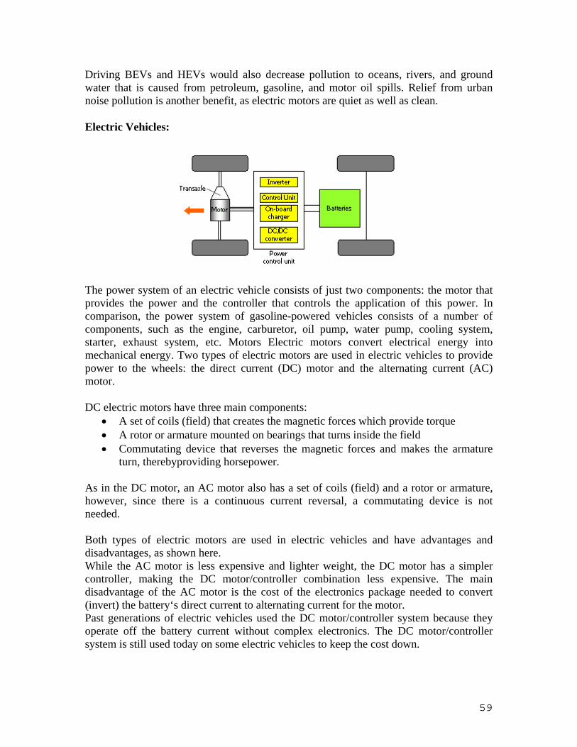
59
Driving BEVs and HEVs would also decrease pollution to oceans, rivers, and ground water that is caused from petroleum, gasoline, and motor oil spills. Relief from urban noise pollution is another benefit, as electric motors are quiet as well as clean.
Electric Vehicles:
The power system of an electric vehicle consists of just two components: the motor that provides the power and the controller that controls the application of this power. In comparison, the power system of gasoline-powered vehicles consists of a number of components, such as the engine, carburetor, oil pump, water pump, cooling system, starter, exhaust system, etc. Motors Electric motors convert electrical energy into mechanical energy. Two types of electric motors are used in electric vehicles to provide power to the wheels: the direct current (DC) motor and the alternating current (AC) motor. DC electric motors have three main components:
• A set of coils (field) that creates the magnetic forces which provide torque • A rotor or armature mounted on bearings that turns inside the field • Commutating device that reverses the magnetic forces and makes the armature
turn, therebyproviding horsepower. As in the DC motor, an AC motor also has a set of coils (field) and a rotor or armature, however, since there is a continuous current reversal, a commutating device is not needed. Both types of electric motors are used in electric vehicles and have advantages and disadvantages, as shown here. While the AC motor is less expensive and lighter weight, the DC motor has a simpler controller, making the DC motor/controller combination less expensive. The main disadvantage of the AC motor is the cost of the electronics package needed to convert (invert) the battery‘s direct current to alternating current for the motor. Past generations of electric vehicles used the DC motor/controller system because they operate off the battery current without complex electronics. The DC motor/controller system is still used today on some electric vehicles to keep the cost down.

60
However, with the advent of better and less expensive electronics, a large number of today’s electric vehicles are using AC motor/controller systems because of their improved motor efficiency and lighter weight. These AC motors resemble motors commonly used in home appliances and machine tools, and are relatively inexpensive and robust. These motors are very reliable, and since they have only one moving part, the shaft, they should last the life of the vehicle with little or no maintenance. Electric Motor Comparison AC Motor DC Motor Single - speed transmission Multi-speed transmission Light weight Heavier for same power Less expensive More expensive 95% efficiency at full load 85-95% efficiency at full load More expensive controller Simple controller Motor/Controller/Inverter more expensive Motor/controller less expensive Controllers or Power Electronics Controllers The electric vehicle controller is the electronics package that operates between the batteries and the motor to control the electric vehicle‘s speed and acceleration much like a carburetor does in a gasoline powered vehicle. The controller transforms the battery’s direct current into alternating current (for AC motors only) and regulates the energy flow from the battery. Unlike the carburetor, the controller will also reverse the motor rotation (so the vehicle can go in reverse), and convert the motor to a generator (so that the kinetic energy of motion can be used to recharge the battery when the brake is applied). In the early electric vehicles with DC motors, a simple variable-resistor-type controller controlled the acceleration and speed of the vehicle. With this type of controller, full current and power was drawn from the battery all of the time. At slow speeds, when full power was not needed, a high resistance was used to reduce the current to the motor. With this type of system, a large percentage of the energy from the battery was wasted as an energy loss in the resistor. The only time that all of the available power was used was at high speeds.
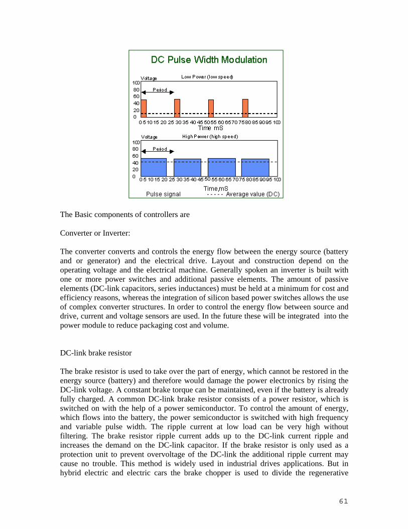
61
The Basic components of controllers are
Converter or Inverter: The converter converts and controls the energy flow between the energy source (battery and or generator) and the electrical drive. Layout and construction depend on the operating voltage and the electrical machine. Generally spoken an inverter is built with one or more power switches and additional passive elements. The amount of passive elements (DC-link capacitors, series inductances) must be held at a minimum for cost and efficiency reasons, whereas the integration of silicon based power switches allows the use of complex converter structures. In order to control the energy flow between source and drive, current and voltage sensors are used. In the future these will be integrated into the power module to reduce packaging cost and volume. DC-link brake resistor The brake resistor is used to take over the part of energy, which cannot be restored in the energy source (battery) and therefore would damage the power electronics by rising the DC-link voltage. A constant brake torque can be maintained, even if the battery is already fully charged. A common DC-link brake resistor consists of a power resistor, which is switched on with the help of a power semiconductor. To control the amount of energy, which flows into the battery, the power semiconductor is switched with high frequency and variable pulse width. The ripple current at low load can be very high without filtering. The brake resistor ripple current adds up to the DC-link current ripple and increases the demand on the DC-link capacitor. If the brake resistor is only used as a protection unit to prevent overvoltage of the DC-link the additional ripple current may cause no trouble. This method is widely used in industrial drives applications. But in hybrid electric and electric cars the brake chopper is used to divide the regenerative

62
power between the battery and the brake resistor. The amount of brake power flowing into the battery depends on its state of charge. DC-link main connector For safety reason the energy storage system and the drive system must be separable. In case of failure the disconnection has to be triggered automatically. The DC-link main connector can separate the energy source and all the other power electronics function blocks.This is not only meant for safety reason at maintenance work, but also for protection of the battery in case of power electronics failure (short circuit). Therefore it is necessary that the main connector can switch at current ratings well above the nominal current. The Hybrid I11 uses an experimental prototype of a vacuum switch from Kilovac/ USA. Vacuum switches are probably the only ones which offer high switching capability with low conduction losses and small volume. An electronic circuit has been developed to reduce the loss in the switching coil. After an initial step of 12V the voltage across the switching coil is reduced down so that the losses are reduced to less than 3 W. Battery charger The battery charging system should run independently from the rest of the power electronics, allowing the user to charge the batteries overnight. A constant monitoring, i.e. a battery management system is necessary to prevent from damages as a consequence of overload or a deep discharge. The battery charger must meet different specifications given by utility companies and battery manufacturers. Low current harmonics, power factor control and electrical isolation are used to meet the specification of the utility companies. The battery management includes a constant control of the battery charge level as well as of the allowed current and voltage. As in most cases the battery consists of several series connected cell blocks, the battery charger must avoid asymmetrical charging and discharging. This problem increases with the number of series connected cells. The control of the terminal voltage is not a sure indication for the state of charge. The Hybrid I11 uses a charging system which controls actively the state of charge for each 12V block of the battery. Under load it can charge the weaker cells from the stronger ones and therefore increases the usable amount of battery capacity. To reach a unit power factor advanced battery charger systems are using an input step-up converter with power factor control. The input current is controlled to be sinusoidal and in phase with the line voltage. The output voltage of the step-up converter is higher than the rectified line voltage to ensure power flow over the whole line period. The output voltage of the step-up converter could be connected directly to the terminal voltage of the battery. By varying the output voltage of the output voltage the charging current can be controlled. If electrical isolation is needed as required by different regulations a second DC/DC-converter after the step-up converter is used. The output of this DC/DC-converter is connected to the terminals of the battery and only the terminal voltage can be controlled. The disadvantage of the second solution is the necessity of two entire power electronic circuits with two independent control circuits. Also because of the sinusoidal

63
input power flow, a relatively large input capacitor is needed in both cases. Furthermore, by controlling only the terminal voltage there is no valid indication of the state of charge. This is especially true with higher system voltages, as this requires a large number of series connected cells. If one of the series connected cells has less capacity than the majority of the cells it will be discharged to a lower cell voltage and therefore, as the internal resistance rises at the end of discharging, have more losses with same load current. This results in a higher temperature and a shorter service life. If after this, only the terminal voltage of the cellblock is used to detect the end of charge, it is likely, that overvoltage of the other cells is hiding the low voltage of the weaker cell. To only way to prevent this is overcharging with a factor of 110 to 140%. This results in a lower charging efficiency and an increased temperature of the other cells at the end of charge. Board power supply The board power supply converts the energy from the main energy source to the traditional 12V consumers in a car. The maximum power for the board power supply is given with the maximum power used by all 12V consumers. It delivers also the different supply levels used in the power electronics function blocks and should therefore integrated with the converter. Battery Charging system: There are essentially two approaches to #e charging of electrical vehicle batteries:
• conductive coupling in which the charging source is connected directly to the vehicle and
• inductive coupling in which a take-apart transformer is used to transfer the charging power to the car. These two approaches will now be discussed.
CONDUCTIVE COUPLING Conductive coupling employs the conventional conductive contact in which the user connects the off-vehicle source of charging power directly to the car. An example of a typical concept for a suggested charging infrastructure based on conductive coupling is shown in Fig.

64
INDUCTIVE COUPLING Inductive coupling is a method of transferring electrical power from the source to the load magnetically rather than by direct ohmic contact. Inductive coupling, in various forms, has been considered as a viable robust and safe power transfer approach in such areas as mining and underwater power delivery, but it is also naturally suited to the area of EV charging. The practical application of inductive coupling as employed in the charging of the GM EVl is illustrated in Fig above. The basic principle underlying inductive coupling is #at the two halves of the inductive coupling interface are the primary and secondary of a separable two-part transformer. When the charge coupler is juxtaposed with the vehicle inlet (i.e. the secondary), power can be transferred magnetically with complete electrical isolation, as with a standard transformer. The coupler and vehicle inlet featured in EV1 are shown in Fig. 3. The coupler is attached via the cable to the off-vehicle charging module. When the coupler is inserted into the vehicle inlet, power from the coupler is transformer coupled to the secondary, rectified and fed to the battery by the battery cable. Note that the coupler contains a ferrite block or "puck" at the center of the primary winding to complete the magnetic path when the coupler is inserted into the vehicle inlet. The simplified power flow diagram for inductive charging of the EV1 is shown in Fig below. The charger converts the low frequency utility power to high frequency ac (HFAC) power. The WAC is transformer-coupled at the vehicle inlet, rectified and supplied to the batteries.

65
Hybrid Electric Vehicles: An HEV is a cross between an electric vehicle and a conventional internal combustion engine (ICE) vehicle. Hybrid electric and electric cars are classified according their use of energy sources and drive systems. The hybrid electric vehicle categories include the series and parallel hybrid as well as the range extender or mixed hybrid A. Parallel Hybrid The parallel hybrid has two independent drive systems. Each of them can contribute power to accelerate the vehicle. They can share a common driving axle (one axle parallel hybrid) or not (two axle or split parallel hybrid). The combination of them should result in a better efficiency. For this reason, in a parallel hybrid vehicle the combination of a full sized internal combustion engine together with a smaller electrical machine is mostly used. The electrical drive overcomes the typically low efficiency of the internal combustion engine at low load. The electrical drive system consist of the energy storage medium and the needed power electronics. B. Series Hybrid The series hybrid vehicle uses an internal combustion engine to produce electrical power which is then used by the electrical drive system. Connected to the DC-Link is a battery to provide short time acceleration power or to restore braking power. Therefore the internal combustion engine can be operated at it’s best efficiency. Like the parallel hybrid zero-emission driving is possible and unlike the latter even at full load. The installation of three times of the needed power (ICE, Generator, Motor) and the need of a battery, even of a small one, did longtime make the series hybrid the second choice. Recent progress in power electronics and electrical machines did bring the series hybrid into focus again. C. Hybrid with short time storage medium Recent development in the control of internal combustion engines makes it favorable to operate the engine at part load in a odoff mode. Highest efficiency can be reached. In this system a short time storage medium is necessary to do the averaging for the constant load power demand. This is done with an mechanical flywheel. A continuous variable transmission is needed between the flywheel and the wheel. With the progress in

66
development of super capacitors the mechanical link engine, flywheel and transmission can be replaced by an electrical solution. Basic Components of an Hybrid System The basic components of an Hybrid electric vehicles are:
• I.C. Engines • Electric Motor • System Controller
I.C Engines: Internal Combustion Engines act as a source of power during the rural driving conditions, where the emission norms are not that much stringent. To further reduce emissions, the ICE runs on an alternative fuel, such as, compressed natural gas, ethanol, methanol or propane. The ICE operates to provide energy to power the car and, in some cases, to recharge the batteries Electric Motor: The electric motor is used in the opposite manner during times of low engine load. The electric motor actually loads down the engine when there is little load on the engine, as during deceleration or when coasting down a steep grade. During this time, the motor acts as a generator, and recovers some of the vehicle’s kinetic energy. This process is called regeneration. Regeneration is also used during braking, where the energy is recovered into the batteries instead of wasting the energy as heat developed by friction. The electric motor acts as a buffer for the IC engine in this system. The relationship between the IC engine and electric motor uses the best aspects of each system. The electric motor absorbs some of the transients encountered by the system. The electric motor is more efficient than the IC engine during these transient periods. The IC engine provides the extended range that the electric motor cannot. System Controller: The system controller for the hybrid electric vehicle is a microprocessor based system that manages the electric drive system for the vehicle. The objective of the system controller is to incorporate the electric motive power of the vehicle to increase fuel economy and reduce emissions, while being transparent to the operator. A block diagram of the system controller and related systems is shown in Figure below. The system controller monitors several IC engine signals, the status of the battery pack, and driver control signals to determine the usage of electric motor power.

67
Layout and working of Hybrid Vehicle:
The parallel structure of the HEV requires that both electric power and the IC engine must be able to provide power to the wheels. The electric motor is coupled to the wheels via the original transmission A transfer case supports the electric motor and encloses a high-velocity chain drive that connects to an extension from the transmission shaft. This is one of the most critical aspects of the mechanical design. The sizing of the electric motor and controller is of vital importance to the HEV performance. The electric drive system is matched to operate with the existing powertrain. Since the electric motor and IC engine are connected in a parallel structure, the maximum speed of the motor is at least that of the IC engine (6000 revolutions per minute, rpm). The power output of the motor is also sized to allow for some limited operation as a ZEV. The motorkontroller pair is physically small enough to maintain the functionality of the vehicle.

68
The input and output signals of the microcontroller are conditioned to interface with different systems on the vehicle through a custom designed interface board. The system controller monitors signals from three major systems: the IC engine and powertrain control module (PCM), the driver input signals, and the main battery pack. By observing these signals, the system controller can determine how much electric power to deliver or absorb depending upon driving conditions. There are four main signals that are produced by sensors on the IC engine that are of critical importance for HEV operation. The absolute intake manifold pressure or MAP is significant due to the fact that it directly relates to the load on the engine [9]. The engine speed signal in rpm, is significant as well as the manifold pressure because it has a dramatic effect on fuel economy. In general, for a given manifold pressure, fuel consumption increases with engine speed [lo]. This is due to the fact that as the engine runs faster, more fuel is delivered to the constant volume of the engine cylinders. The engine speed signal is measured from the tachometer output from the PCM. The PCM determines the engine speed based upon the crank and camshaft signals it receives. The manifold pressure and engine speed can be used to determine an engine load function that corresponds to the amount of torque being produced by the engine The engine coolant temperature signal is significant for similar reasons. Emissions levels and fuel consumption are at their highest when the engine is relatively cold. The engine coolant temperature (ECT) signal is a voltage from one of the PCM inputs. The oil pressure switch input is a digital signal that is on when the engine oil pressure reaches a minimum level. This occurs only when the engine is running. In ZEV mode, the engine must be off and, in HEV mode, the engine must be running to determine the validity of the other engine sensor signals. The operator input signals are perhaps the most important input signals because they reflect the intentions of the driver. The throttle position signal is an analog voltage that comes from a potentiometer on the throttle body. The TPS is mainly used in the ZEV mode to allow the operator to increase speed. The brake position signal is used to control the regenerative braking capabilities of the vehicle in the HEV and ZEV modes of operation. The clutch signal is a digital signal that represents the position of the clutch pedal. This signal comes from a clutch switch mounted at the top of the clutch pedal. When the clutch is at rest a low signal is output and when the clutch is slightly depressed a high signal is output. This signal is used differently for the various modes of operation. In ZEV mode, it is necessary for the clutch to be fully engaged to prevent the electric motor from turning the input shaft of the IC engine. In hybrid and IC mode, when the clutch is depressed, no torque is being applied to the transmission input shaft. This prevents the motor from loading down the transmission and allows for proper shifting. The two other user selectable inputs are the vehicle mode and regeneration control inputs. These inputs are digital signals that are provided by the two switches located in the center console. The mode switch sets a two-bit pattem depending upon whether ZEV, HEV, or IC mode is selected. The regeneration switch outputs a single bit that allows the user to turn the regeneration control on or off during the IC and HEV modes. The regeneration control in ZEV mode is not user selectable and is only regulated by the system controller.

69
The battery pack voltage is of significant importance to the system controller. The battery pack voltage is significant due to the charge maintaining strategy of the hybrid vehicle. That is, the engine load function, previously mentioned, can be modified to keep the batteries at as high a SOC as possible for the given driving and operating conditions. The system controller’s primary function is to control the operation of the electric motor . This is accomplished via two main control signals that are input to the motor controller. The desired speed signal is analogous to a vehicle accelerator pedal. This signal is carefully controlled to ensure the safety, reliability, and functionality of the vehicle. The desired speed signal controls the amount of electrical assist in HEV mode. In ZEV mode, the desired speed signal actually controls the speed of the vehicle. The regen control signal determines the amount of braking torque that will be applied to the vehicle. This signal is used for several charging modes in the vehicle. In the ZEV mode, the regen control output controls the regenerative braking aspect of the vehicle. In the IC mode, the regen control signal allows for idle charging of the batteries, In HEV mode, regenerative braking and idle charging during times of low engine load are controlled by the regen control output signal.