Challenges with Thermal Combustion Stage in Sulphur Recovery ...
description

Mo
du
le N
o. 1
2 :
Gas
pro
cess
ing
U
nit
No
. 5
- S
ulp
hu
r re
co
very
un
it
Page 1/13

UNITS IN THIS COURSE
UNIT 1 GAS COMPRESSION SYSTEMS
UNIT 2 AMINE GAS SWEETENING UNIT
UNIT 3 NATURAL GAS LIQUIDS (NGL) RECOVERY UNIT
UNIT 4 GAS FRACTIONATION PLANT
UNIT 5 SULPHUR RECOVERY UNIT
Page 2/13

Mo
du
le N
o. 1
2 :
Gas
pro
cess
ing
U
nit
No
. 5
- S
ulp
hu
r re
co
very
un
it
Page 3/13

TABLE OF CONTENTS
Para Page
5.0 COURSE OBJECTIVE 3
5.1 INTRODUCTION 4
5.2 FUNCTIONS OF THE SULPHUR RECOVERY UNIT EQUIPMENT 5
5.3 BASIC FUNCTIONS OF THE SULPHUR PLANT 7
5.3.1 Basic Description of the Reaction that Produces Sulphur 8
5.4 DESCRIPTION OF THE FLOW OF GAS THROUGH THE SULPHUR UNIT 9
5.4.1 Acid Gas Feed System 9
5.4.2 Reaction Furnace and Waste Heat Boiler 10
5.4.3 No 1 Condenser 11
5.4.4 No 1 Reheater and No 1 Converter 12
5.4.5 No 2 Condenser 12
5.4.6 No 2 Reheater and No 2 Converter 12
5.4.7 No 3 Condenser 12
5.4.8 No 3 Reheater and No 3 Converter 13
5.4.9 No 4 Condenser 13
5.4.10 Incinerator 13
5.4.11 Sulphur
Storage Pit 13
Page 4/13

Mo
du
le N
o. 1
2 :
Gas
pro
cess
ing
U
nit
No
. 5
- S
ulp
hu
r re
co
very
un
it
Page 5/13
5.0 OBJECTIVE
On completion of this unit the trainee will be able to:
Describe and identify the most important pieces of equipment used in a sulphur recovery unit.
Describe the functions of each piece of equipment used in the sulphur recovery process.
Page 6/13

Mo
du
le N
o. 1
2 :
Gas
pro
cess
ing
U
nit
No
. 5
- S
ulp
hu
r re
co
very
un
it
Page 7/13
5.1 INTRODUCTION
The process used in the sulphur recovery unit is called the "Claus" process. In this process both catalytic and non-catalytic methods are used to combine hydrogen sulphide (H2S) with sulphur dioxide to produce sulphur.
Depending on the percentage of H2S in the feed gas, a portion of the feed is burned in the reaction furnace with a carefully controlled .amount of air. The rest of the feed flows directly to the first catalytic converter.
This type of split flow makes the conversion to sulphur more efficient, (up to 98%). The high and stable temperatures produced by the acid gas burner ensure maximum conversion takes place in the thermal section.
Chemically, when H2S is burned with air it oxidises into sulphur dioxide. If the burning is done using a controlled amount of air, only a portion of H 2S is oxidised producing chemical sulphur, H2S and SO2.
With the help of a catalyst it is possible to combine the H2S and SO2. to produce sulphur and water. In this process H2S is burned under controlled conditions. These conditions produce just the right amount of sulphur dioxide required to catalytically combine with the unburnt H2S
Approximately 33 % of the H2S in the feed oxidises to S02. This gives a ratio of H2S to SO2 throughout the plant of 2:1. This is the ideal ratio for producing sulphur.
The catalytic conversion is done in three converters. Unconverted H2S and SO2
from the reaction furnace is reheated, mixed with hot H2S from the bypass line and fed to No 1 converter.
Page 8/13

Mo
du
le N
o. 1
2 :
Gas
pro
cess
ing
U
nit
No
. 5
- S
ulp
hu
r re
co
very
un
it
Page 9/13

5.2 FUNCTIONS OF THE SULPHUR RECOVERY UNIT EQUIPMENT
Figure 5-1 Gas Flow through Sulphur Recovery Unit
Acid Gas Knockout Drum
The acid gas knockout drum is used to separate the liquids (sour. water) from the acid gases.
The sour water is pumped to the sour water unit.
Preheater
High pressure steam is used in the preheater to increase the temperature of the acid gases. Increasing the temperature of the acid gases will give good combustion in the reaction furnace.
Reaction Furnace
In the reaction furnace 2/3 rds (66 %) of the acid gas stream is combined with a controlled amount of air. This is to ensure combustion of 1/3rd of the hydrogen sulphide (H2S) to sulphur dioxide (SO2).
Some of the hydrogen sulphide (H2S) and sulphur dioxide SO2 are also combined to produce sulphur vapours and water.
Page 10/13

Mo
du
le N
o. 1
2 :
Gas
pro
cess
ing
U
nit
No
. 5
- S
ulp
hu
r re
co
very
un
it
Page 11/13

Waste Heat Boiler
The waste heat boiler removes the heat energy that is produced by the combustion of H2S
Boiler feed water is used in the waste heat boiler for cooling the hot gases.
The waste heat boiler uses this heat energy from the combustion of H2S to convert the boiler feed water to high pressure steam for use in the plant.
No 1 Condenser
Boiler feed water is used in the condenser to condense (turn to liquid) all of the sulphur vapours.
The condenser uses the heat energy from the gases to convert the boiler feed water to low pressure steam.
No 1 Reheater
High pressure steam is used in the heat exchanger to increase the temperature of the unconverted acid gases. This ensures a good chemical conversion in the converter.
No 1 Converter
The converter is filled with an activated alumina type catalyst. The catalyst increases the speed of the reaction between the hydrogen sulphide (H2S) and sulphur dioxide (SO2). This chemical reaction produces sulphur vapour and water vapour. This chemical reaction is called an exothermic reaction because it produces heat energy.
No 2 Condenser
Boiler feed water is used in the condenser to condense (turn to liquid) all of the sulphur vapours.
The condenser uses the heat energy from the gases to convert the boiler feed water to low pressure steam.
No 2 and No 3 Reheater
High pressure steam is used in the heat exchanger to increase the temperature of the unconverted gases. This ensures a maximum conversion in the downstream converters.
No 2 and No 3 Converters
The converters are filled with an activated alumina type catalyst. The catalyst increases the speed of the reaction between the hydrogen sulphide (H2S) and sulphur dioxide (SO2). This chemical reaction produces sulphur vapour and water vapour. It is an exothermic reaction.
Page 12/13

Mo
du
le N
o. 1
2 :
Gas
pro
cess
ing
U
nit
No
. 5
- S
ulp
hu
r re
co
very
un
it
Page 13/13
No 3 Condenser
Boiler feed water is used in the condenser to condense all the sulphur vapours produced in No 2 converter to liquid sulphur.
The condenser uses the heat energy from the gases to convert the boiler feed water to low pressure steam.
No 4 Condenser
Boiler feed water is used in the condenser to condense the final sulphur vapours produced in No 3 converter to liquid sulphur.
The condenser uses the heat energy from the gases to increase the temperature of the boiler feed water before it flows to the waste heat boiler.
Incinerator
Any unconverted gas from No 4 converter flows to the incinerator. The incinerator burns all the waste gases at 600'C and changes them to inert products. They are oxidised to SO2 before they are discharged to the atmosphere via the incinerator stack.
5.3 BASIC FUNCTIONS OF THE SULPHUR PLANT
To take the H2S and convert (change) it to sulphur for sales.
To burn all other waste gases to reduce pollution and to protect the environment.
Page 14/13

Mo
du
le N
o. 1
2 :
Gas
pro
cess
ing
U
nit
No
. 5
- S
ulp
hu
r re
co
very
un
it
Page 15/13

HOW HYDROGEN SULPHIDE (H2S) IS CONVERTED TO SULPHUR
The hydrogen sulphide (H2S) is combined with sulphur dioxide (SO2) to produce sulphur and water in a catalytic reaction.
The sulphur which is produced is then condensed and removed in liquid form.
5.3.1 Basic Description of the Reaction that Produces Sulphur
2/3 rds (66 %) of the hydrogen sulphide (H2S) is combined with a controlled amount of air and burned in a reaction furnace.
50 % of the hydrogen sulphide (H2S) gas in the furnace oxidises and becomes sulphur dioxide (SO2).
The remaining hydrogen sulphide (H2S) is combined with the sulphur dioxide (SO2) with the help of a catalyst to produce sulphur and water.
The chemical reactions which happen are:
The H2S gas burns to produce SO2
If the H2S and SO2 are in a ratio of 2:1, they will combine to produce sulphur.
THE SULPHUR PRODUCING REACTION HAPPENS IN TWO WAYS
Automatically (non-catalytic)
Due to the high temperature in the reaction furnace some H2S + SO2 react to form sulphur + water.
Catalytically (with the help of a catalyst)
In the converter beds the activated alumina catalyst causes the reaction -to take place at a lower temperature.
THE SULPHUR PLANT PRODUCES ONE MAIN BY-PRODUCT
A large amount of heat energy. This is because the chemical processes a re exothermic.
This heat energy is used to produce steam at different pressures for use throughout the plant site. Some examples are:
To preheat boiler feed water To preheat the acid gases To drive steam turbines.
Page 16/13

Mo
du
le N
o. 1
2 :
Gas
pro
cess
ing
U
nit
No
. 5
- S
ulp
hu
r re
co
very
un
it
Page 17/13

5.4 DESCRIPTION OF THE FLOW OF GAS THROUGH THE SULPHUR UNIT
5.4.1 Acid Gas Feed System
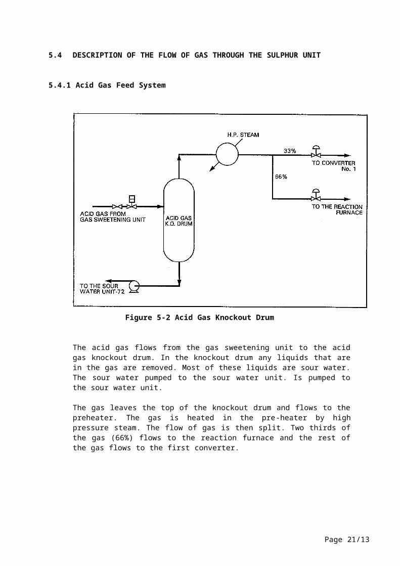
Figure 5-2 Acid Gas Knockout Drum
The acid gas flows from the gas sweetening unit to the acid gas knockout drum. In the knockout drum any liquids that are in the gas are removed. Most of these liquids are sour water. The sour water pumped to the sour water unit. Is pumped to the sour water unit.
The gas leaves the top of the knockout drum and flows to the preheater. The gas is heated in the pre-heater by high pressure steam. The flow of gas is then split. Two thirds of the gas (66%) flows to the reaction furnace and the rest of the gas flows to the first converter.
Page 18/13

Mo
du
le N
o. 1
2 :
Gas
pro
cess
ing
U
nit
No
. 5
- S
ulp
hu
r re
co
very
un
it
Page 19/13

5.4.2 Reaction Furnace and Waste Heat Boiler
Figure 5-3 Reaction Furnace / Waste Heat Boiler
Approximately 66 % of the acid gas feed to the sulphur unit flows to the reaction furnace (depending on the acid gas strength). A carefully measured amount of air flows to the reaction furnace. The amount of air depends on the flow of feed to the unit and on the % of H2S that is in the feed. The amount of air flow is controlled automatically so that it burns approx. 1/3 of the H2S.
The normal operating temperature of the reaction furnace is approximately 1200 C. The heat in the reaction furnace is used to make high pressure (HP) saturated steam in the waste heat boiler. The HP steam is made from the boiler feed water that is fed to the waste heat boiler. The steam is separated in the steam drum. The steam leaves the top of the steam drum and flows to the HP saturated steam main.
Page 20/13
Mo
du
le N
o. 1
2 :
Gas
pro
cess
ing
U
nit
No
. 5
- S
ulp
hu
r re
co
very
un
it
Page 21/13

5.4.3 No 1 Condenser
Exhaust gases from the waste heat boiler flow to the first condenser (No 1 condenser). In the first condenser the exhaust gases from the waste heat boiler are used to make low pressure steam (LP). The LP steam is made from the boiler feed water that is fed to the condenser. This process reduces the temperature of the exhaust gases. (See figure 5-1).
Any sulphur gases will be condensed to liquid sulphur. The liquid sulphur flows to a "sulphur seal" which allows liquid sulphur to drain away. However, the "sulphur seal" maintains a gas seal on the liquid in the sulphur seal pot. This seal prevents H2S being released to the atmosphere. (See Figure 5-4).
Figure 5-4 Liquid Sulphur Seal Pot
Page 22/13

Mo
du
le N
o. 1
2 :
Gas
pro
cess
ing
U
nit
No
. 5
- S
ulp
hu
r re
co
very
un
it
Page 23/13

5.4.4 No 1 Reheater and No 1 Converter
See Figure 5-1. The unconverted H2S and SO2, along with CO2 and other gases, leave No. 1 condenser and flow to the No. 1 reheater. Here, the temperature of the gases is increased. After this they combine with the other 33 % of hot gases that by-passed the reaction furnace. (This flow doesn't go through the reaction furnace because if all the gas went through the reaction furnace it would lower the temperature of the reaction furnace).
The combined gases flow to No 1 converter and down onto a catalyst bed. The catalyst, (activated alumina type), increases the speed of the reaction between the H2S and SO2. This reaction converts the gases into sulphur gas. This reaction is exothermic. Therefore the gases which leave the converter are hotter than the gases which go in to the converter. (See figure 5-1).
5.4.5 No 2 Condenser
Hot gases from No 1 converter flow to No 2 condenser. The heat from these gases is used to make the boiler feed water that flows to the condenser into LP steam. As the hot gases cool they condense to liquid sulphur. This liquid sulphur flows through a liquid sulphur seal pot which is the same as the one at No 1 condenser (see figure 3-4). The combined liquid sulphur flows from condensers 1 & 2 go to the liquid sulphur storage pit.
5.4.6 No 2 Reheater and No 2 Converter
The cooled gases from No 2 condenser flow to No 2 reheater. Here, they are reheated by high pressure steam before they flow to No 2 converter. The reaction in No 2 converter is the same as in No 1 converter. Once again H2S and SO2 combine to make sulphur. This reaction is exothermic so the temperature of the gases is increased again. (See figure 5-1).
5.4.7 No 3 Condenser
No 3 condenser is the same as No 2 condenser. Hot gases from No 2 converter flow to No 3 condenser. Boiler feed water also flows into this condenser. The heat from the gases is used to change the boiler feed water into LP steam. This cools the hot gases and they condense to liquid sulphur. This liquid sulphur flows through a liquid sulphur seal pot which is the same as the one at No 1 and No 2 condensers. The liquid sulphur flows to the liquid sulphur storage pit.
Page 24/13

Mo
du
le N
o. 1
2 :
Gas
pro
cess
ing
U
nit
No
. 5
- S
ulp
hu
r re
co
very
un
it
Page 25/13

5.4.8 No 3 Reheater and No 3 Converter
The cooled gases from No 3 condenser are heated by HP steam in No 3 reheater. No 3 converter is the same as No 1 and No 2 converters and the same reaction takes place.
5.4.9 No 4 Condenser
The hot gases from No 3 converter flow to No 4 condenser. The gases are cooled by boiler feed water. The hot gases condense to liquid sulphur. The liquid sulphur combines with the liquid sulphur from No 3 condenser and flows to the liquid sulphur storage pit. It is important to keep the gases leaving No.4 condenser hot enough to prevent H20 vapour from condensing to water. If water comes into contact with sulphur it will form sulphuric acid which will corrode ducting in the incinerator.
5.4.10 Incinerator
Any unconverted gas from No 4 condenser flows to the incinerator. In the incinerator any H2S. organic sulphur or sulphur vapour are oxidised to SO2. The oxidised vapours are then discharged to the atmosphere through the incinerator stack.
5.4.11 Sulphur Storage Pit
The liquid storage pit is designed to store at least one day's sulphur production. The contents of the pit are transferred to the liquid sulphur storage tanks as required. In the base of the pit there are heating coils which are heated by LP steam. The heat from the coils keeps the stored sulphur in a liquid state.
Page 26/13