Unit 33 Three-Phase Motors -...
73
Unit 33 Three-Phase Motors
-
Upload
hoangduong -
Category
Documents
-
view
226 -
download
0
Transcript of Unit 33 Three-Phase Motors -...
Unit 33
Three-Phase Motors

Unit 33 Three-Phase Motors
Objectives:
• Discuss the basic operating principles of
three-phase motors.
• List factors that produce a rotating
magnetic field.
• List different types of three-phase motors.

Unit 33 Three-Phase Motors
Objectives:
• Discuss the operation of squirrel-cage motors.
• Show connection of dual-voltage motors for proper operation on the desired voltage.
• Discuss the operation of consequent pole motors.

Unit 33 Three-Phase Motors
Objectives:
• Discuss the operation of wound rotor motors.
• Discuss the operation of selsyn motors.
• Discuss the operation of synchronous
motors.
• Determine the direction of rotation of a three-
phase motor using a phase rotation meter.

Unit 33 Three-Phase Motors
• Three-phase motors are used throughout the U.S. and Canada as the prime mover for industry.
• These motors convert three-phase AC into mechanical energy to operate all types of machinery.
• They are smaller, lighter, and have higher efficiencies per horsepower than single-phase motors.
Unit 33 Three-Phase Motors
• Three-phase motors are extremely rugged
and require minimal maintenance.
• These motors can be operated 24/7 for
years without problems.
• Nikola Tesla patented the first induction
motors as rotating transformers.
Unit 33 Three-Phase Motors
Construction
There are three basic types of three-
phase motors:
1. squirrel-cage induction motor
2. wound-rotor induction motor
3. synchronous motor
Unit 33 Three-Phase Motors
Rotating Magnetic Field
• The principle of operation for all three-phase motors is the rotating magnetic field.
• The magnetic field rotation is caused by:
– voltages are 120° out of phase.
– voltages periodically change polarity.
– the arrangement of the stator windings.

Unit 33 Three-Phase Motors
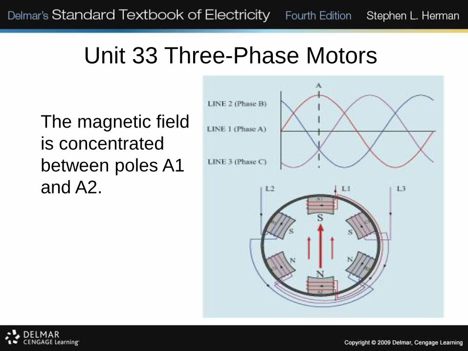
Three-phase stator
and three voltage
sine waves.
Unit 33 Three-Phase Motors
The magnetic field
is concentrated
between poles A1
and A2.
Unit 33 Three-Phase Motors
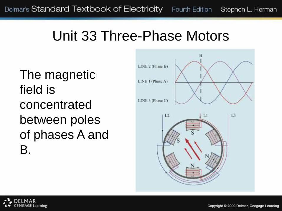
The magnetic
field is
concentrated
between poles
of phases A and
B.

Unit 33 Three-Phase Motors
The magnetic field
is concentrated
between poles B1
and B2.

Unit 33 Three-Phase Motors
The magnetic field
is concentrated
between phases B
and C.

Unit 33 Three-Phase Motors
The magnetic field is
concentrated
between poles C1
and C2.

Unit 33 Three-Phase Motors
The magnetic field is
concentrated
between phases A
and C.
Unit 33 Three-Phase Motors
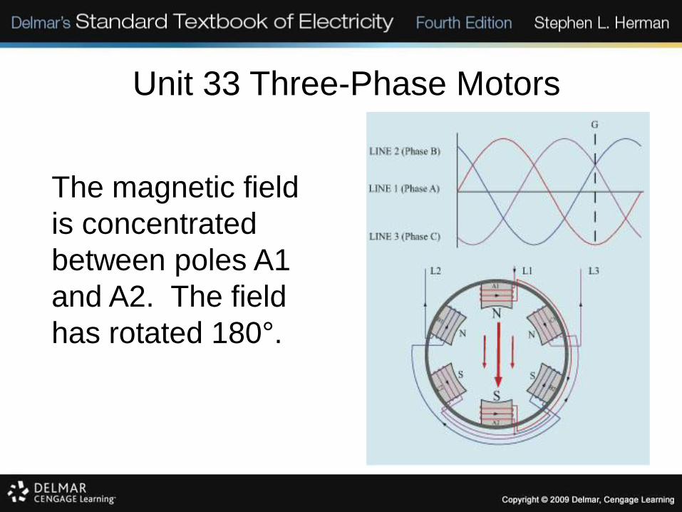
The magnetic field
is concentrated
between poles A1
and A2. The field
has rotated 180°.
Unit 33 Three-Phase Motors
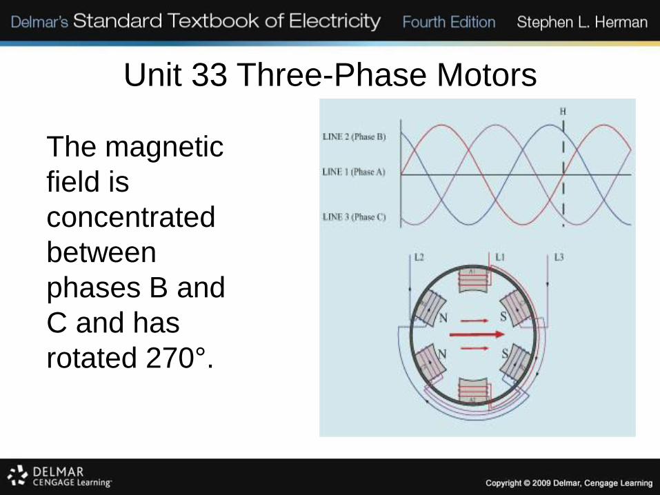
The magnetic
field is
concentrated
between
phases B and
C and has
rotated 270°.

Unit 33 Three-Phase Motors
The magnetic
field is
concentrated
between poles A1
and A2 and has
rotated 360°.
Unit 33 Three-Phase Motors
Synchronous Speed
• Synchronous speed is the rotational
speed of the magnetic field.
• Synchronous speed is determined by:
– the number of stator poles per phase.
– the frequency of the applied voltage.

Unit 33 Three-Phase Motors
RPM STATOR POLES
3600 2
1800 4
1200 6
900 8

Unit 33 Three-Phase Motors
Synchronous Speed
• S = (120 x F) / P
• S = synchronous speed in RPM
• F = frequency in Hz
• P = number of stator poles

Unit 33 Three-Phase Motors
Phase Rotation
• The direction of rotation is either clockwise or counterclockwise.
• Reversing any two of the stator leads will reverse the direction of rotation.
• A phase rotation meter can determine the direction of rotation.
• Motor stator leads are often called T leads.

Unit 33 Three-Phase Motors
Connecting the phase rotation meter to the motor.

Unit 33 Three-Phase Motors
Connecting the phase rotation meter to the line.

Unit 33 Three-Phase Motors
Dual-Voltage Motors
• Many motors are designed to operate on two different voltages, such as 240 V and 480 V.
• This type of motor has two windings for each phase.
• Most dual-voltage motors bring out 9 leads to the terminal box.
Unit 33 Three-Phase Motors
Dual-Voltage Motors
• The other 3 leads are connected internally.
• Review: There are two connection leads per winding; there are two windings per phase; there are three phases. This makes 12 connection leads. Of these 12 leads 9 are usually brought out to the terminal box, 3 are connected internally.
Unit 33 Three-Phase Motors
Dual-Voltage Motors
• When motors are connected to their
higher-rated voltage on the name plate, a
high-voltage connection pattern is
required.
• When motors are connected to their
lower-rated voltage on the name plate, a
low-voltage connection pattern is required.

Unit 33 Three-Phase Motors
Dual-Voltage Motors
• The identification of connection leads is
standardized to T1 through T12.
• The correct connection patterns are
usually shown on the motor name plate.
• The NEC® states the required name plate
data.

Unit 33 Three-Phase Motors
Standard numbering for three-phase motors.

Unit 33 Three-Phase Motors
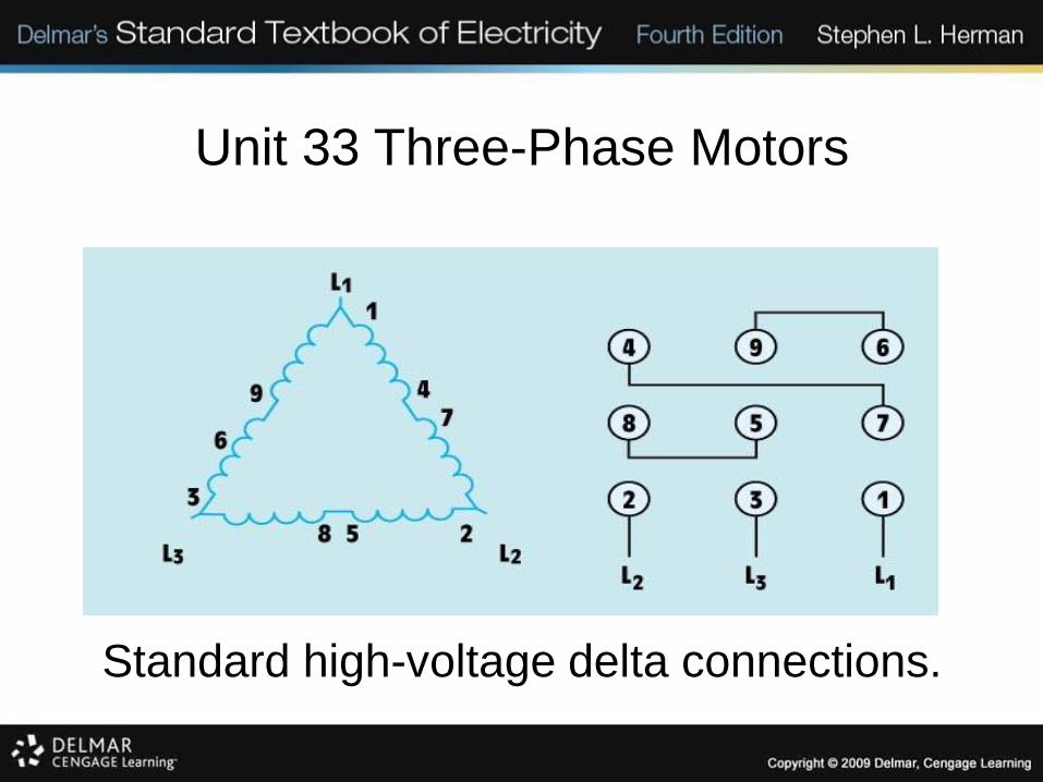
High-Voltage Connections
• High-voltage connections require the windings to be series configured.
• The high-voltage connections can be either wye or delta, depending on how the motor was constructed and designed.
• A terminal chart is another way to identify proper T lead connections.
Unit 33 Three-Phase Motors
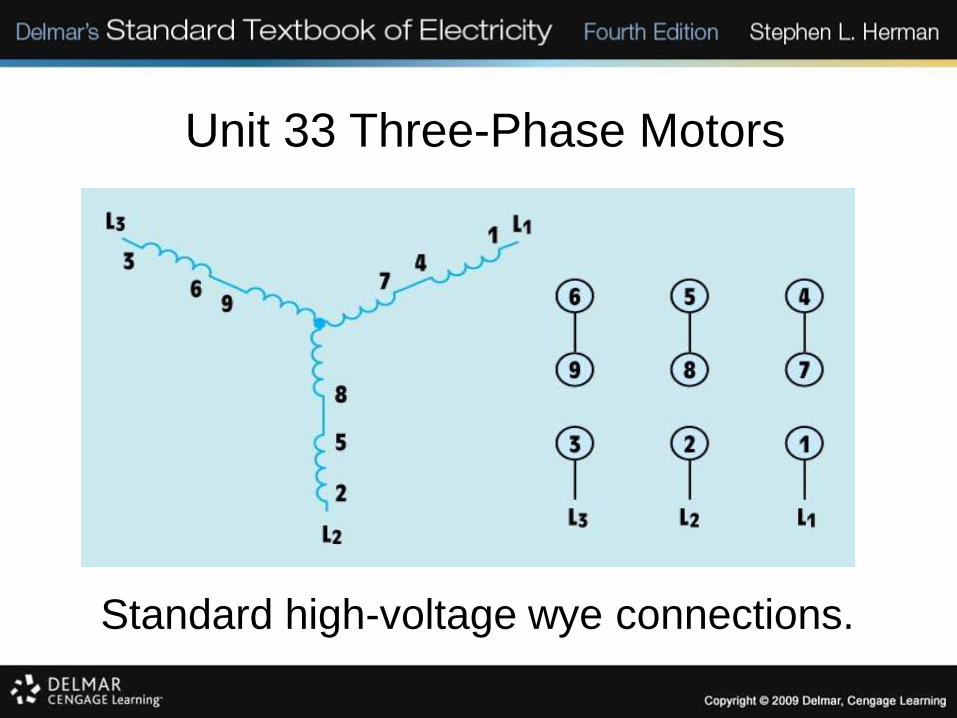
Standard high-voltage wye connections.
Unit 33 Three-Phase Motors
Standard high-voltage delta connections.
Unit 33 Three-Phase Motors
Low-Voltage Connections
• Low-voltage connections require the windings to be parallel configured.
• The low-voltage connections can be either wye or delta, depending on how the motor was constructed and designed.
• A terminal chart is another way to identify proper T lead connections.

Unit 33 Three-Phase Motors
Standard low-voltage wye schematic.
Unit 33 Three-Phase Motors
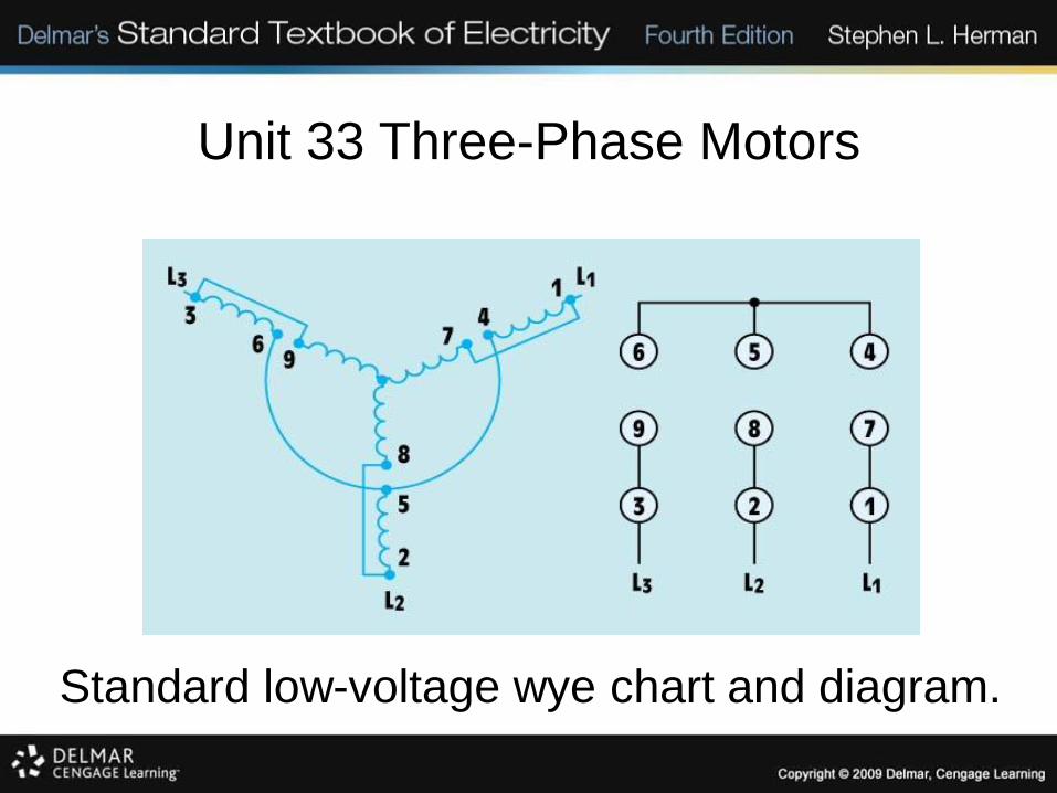
Standard low-voltage wye chart and diagram.
Unit 33 Three-Phase Motors
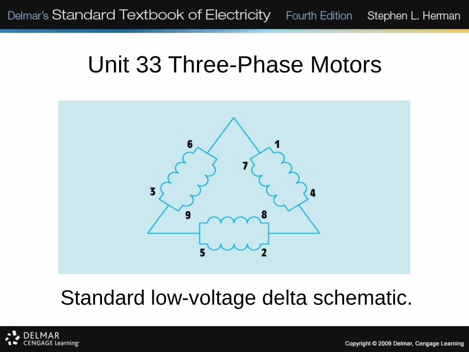
Standard low-voltage delta schematic.

Unit 33 Three-Phase Motors
Standard low-voltage delta chart and diagram.
Unit 33 Three-Phase Motors
12-Lead Dual-Voltage Motors
• Some motors will have 12 T leads brought to the terminal box instead of the usual 9 leads.
• These motors are intended for wye-delta starting.
• Wye-delta starting helps limit inrush starting current.
Unit 33 Three-Phase Motors
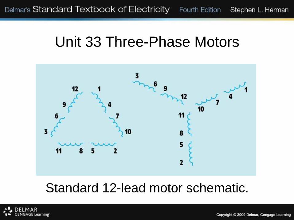
Standard 12-lead motor schematic.
Unit 33 Three-Phase Motors
Squirrel-Cage Induction Motors
• The rotor on this type of motor resembles a squirrel cage.
• The rotor contains bars connected to the end rings.
• The current flow in the rotor is produced by induced voltage from the rotating magnetic field of the stator.

Unit 33 Three-Phase Motors
Basic squirrel-cage rotor without laminations.
Unit 33 Three-Phase Motors
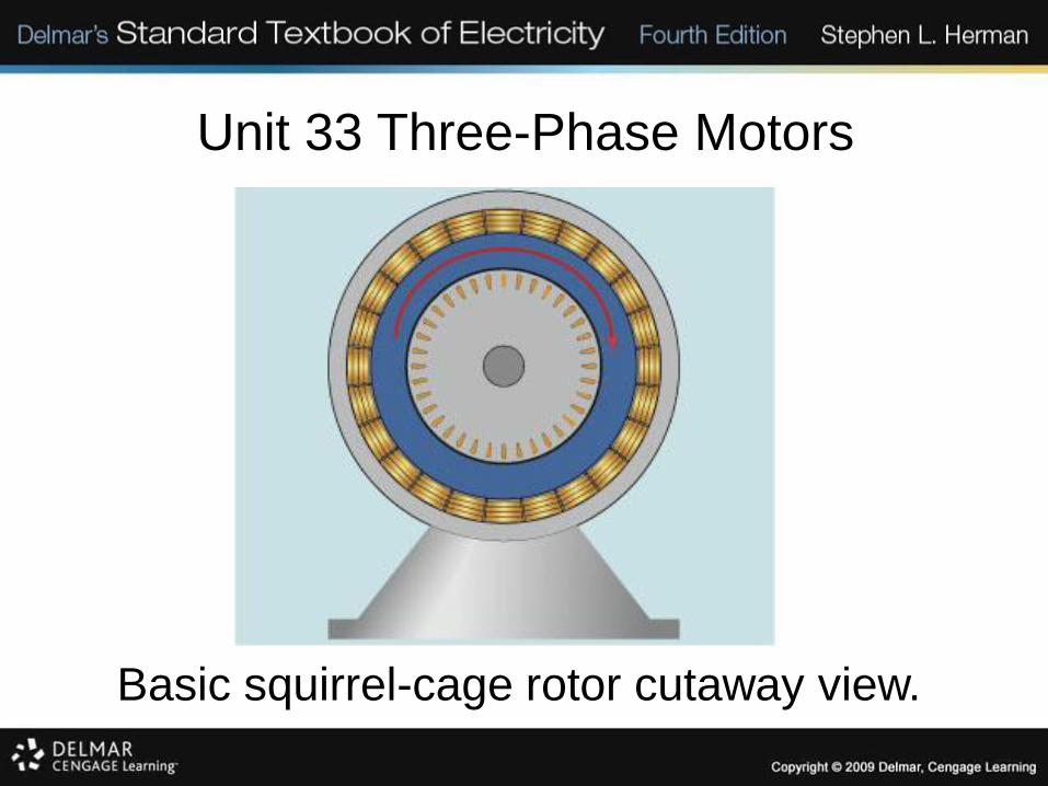
Basic squirrel-cage rotor cutaway view.
Unit 33 Three-Phase Motors
Torque
• Three factors determine the amount of motor torque:
– the strength of the stator magnetic fields.
– the strength of the rotor magnetic fields.
– the phase angle difference between the rotor and stator fields.
Unit 33 Three-Phase Motors
Slip
• An induction motor never reaches
synchronous speed.
• Slip is the difference between
synchronous speed and rotor speed.
• Percent slip is the ratio of slip to
synchronous speed times 100.

Unit 33 Three-Phase Motors
Wound-Rotor Induction Motor
• This motor is very popular in industry because of its high starting torque and low starting current.
• A squirrel-cage motor and a wound-rotor motor have similar stator windings.
• The rotor has wire windings instead of bars.

Unit 33 Three-Phase Motors
External resistors are connected to the rotor of a
wound-rotor motor.

Unit 33 Three-Phase Motors
Wound-rotor motor schematic symbol.
Unit 33 Three-Phase Motors
Synchronous Motors
• This motor is not an induction motor. It does not depend on induced current in the rotor to produce a torque.
• It operates at constant speed from no load to full load.
• This motor must have DC excitation to operate.

Unit 33 Three-Phase Motors
Synchronous motor with DC excitation supplied
through sliprings.

Unit 33 Three-Phase Motors
Synchronous Motors
• The operating speed and the speed of the rotating magnetic field (synchronous speed) are the same.
• It operates at constant speed from no load to full load.
• This motor can be used for power factor correction.
Unit 33 Three-Phase Motors
Synchronous Motors
• A set of squirrel-cage bars known as the amortisseur winding are used to start the synchronous motor.
• A synchronous motor must never be started with DC current connected to the rotor.
• A field-discharge resistor is used to safely control excessive current and voltage.

Unit 33 Three-Phase Motors
The field-discharge resistor is connected in parallel
with the rotor winding during starting.
Unit 33 Three-Phase Motors
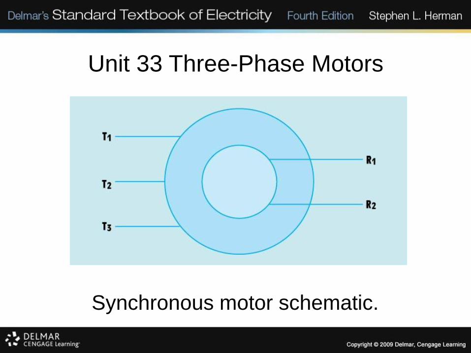
Synchronous motor schematic.
Unit 33 Three-Phase Motors
Selsyn Motors
• Selsyn motors are used for position control and angular feedback information.
• Selsyn motors contain three-phase windings, although they operate on single-phase AC.
• A differential selsyn unit can be used to determine the algebraic rotation sum of two other selsyn units.

Unit 33 Three-Phase Motors
Selsyn motor schematic.

Unit 33 Three-Phase Motors
Selsyn motor schematic symbol.

Unit 33 Three-Phase Motors
Schematic of two selsyn motors connected.

Unit 33 Three-Phase Motors
Schematic of differential selsyn motor connections.

Unit 33 Three-Phase Motors
Review:
1. The basic types of three-phase motors
are:
– squirrel cage induction motor
– wound rotor induction motor
– synchronous motor

Unit 33 Three-Phase Motors
Review:
2. All three-phase motors operate on the principle of a rotating magnetic field.
3. The speed of the rotating magnetic field is called the synchronous speed.
4. The direction of rotation of any three-phase motor can be changed by reversing the connection of any two stator leads.

Unit 33 Three-Phase Motors
Review:
5. Three factors that cause a magnetic field to rotate are:
a. The fact that the voltages of a three-phase system are 120°out of phase with each other.
b. The fact that voltages change polarity at regular intervals.
c. The arrangement of the stator windings.

Unit 33 Three-Phase Motors
Review:
6. Two factors that determine the
synchronous speed are:
a. number of stator poles per phase.
b. frequency of the applied voltage.
Unit 33 Three-Phase Motors
Review:
7. The direction of rotation of a three-phase motor can be determined with a phase rotation meter before power is applied to the motor.
8. Dual-voltage motors will have 9 or 12 leads brought out at the terminal connection box.

Unit 33 Three-Phase Motors
Review:
9. Dual-voltage motors intended for high-
voltage connection have their phase
windings connected in series.
10.Dual-voltage motors intended for low-
voltage connection have their phase
windings connected in parallel.

Unit 33 Three-Phase Motors
Review:
11.Motors that bring out 12 leads are generally intended for wye-delta starting.
12.Maximum torque is developed when stator and rotor flux are in phase with each other.
13.The code letter on the nameplate of a squirrel-cage motor indicates the type of rotor bars used in the rotor construction.
Unit 33 Three-Phase Motors
Review:
14.The torque of an induction motor is
determined by:
a. the magnetic field strength of the stator.
b. the magnetic field strength of the rotor.
c. the phase angle difference between
rotor and stator flux.
Unit 33 Three-Phase Motors
Review:
15.Wound-rotor motors have three sliprings
on the rotor shaft to provide external
connection to the rotor.
16.Wound-rotor motors have higher starting
torque and lower starting current than
squirrel-cage motors of equal horsepower.

Unit 33 Three-Phase Motors
Review:
17.The speed of a wound-rotor motor can be controlled by permitting resistance to remain in the rotor circuit during operation.
18.Synchronous motors operate at a synchronous speed.
19.Synchronous motors operate at a constant speed from no load to full load.

Unit 33 Three-Phase Motors
Review:
20.When load is connected to a synchronous
motor, stress develops between the
magnetic fields of the rotor and stator.
21.Synchronous motors must have DC
excitation from an external source.

Unit 33 Three-Phase Motors
Review:
22.DC excitation is provided to some synchronous motors through two sliprings located on the rotor shaft, and other motors use a brushless exciter.
23.Synchronous motors have the ability to produce a leading power factor by overexcitation of the DC current supplied to the rotor.

Unit 33 Three-Phase Motors
Review:
24. Synchronous motors have a set of type A
squirrel-cage bars used for starting. This
squirrel-cage winding is called the amortisseur
winding.
25. A field-discharge resistor is connected across
the rotor winding during starting to prevent high
voltage in the rotor due to induction.

Unit 33 Three-Phase Motors
Review:
26.Changing the DC excitation current does
not affect the speed of the motor.
27.Selsyn motors are used to provide
position control and angular feedback
information.
Unit 33 Three-Phase Motors
Review:
28.Although selsyn motors contain three-
phase windings, they operate on single-
phase AC.
29.A differential selsyn unit can be used to
determine the algebraic sum of the
rotation of two other selsyn units.