Unit 2 - Audio and Video Compression Ppt
59
Chapter 4 Audio and video compression 4.1 Introduction 4.2 audio compression 4.3 Video compression
-
Upload
vanithapremkumar -
Category
Documents
-
view
151 -
download
18
description
Multimedia
Transcript of Unit 2 - Audio and Video Compression Ppt

Chapter 4 Audio and video compression
4.1 Introduction 4.2 audio compression 4.3 Video compression
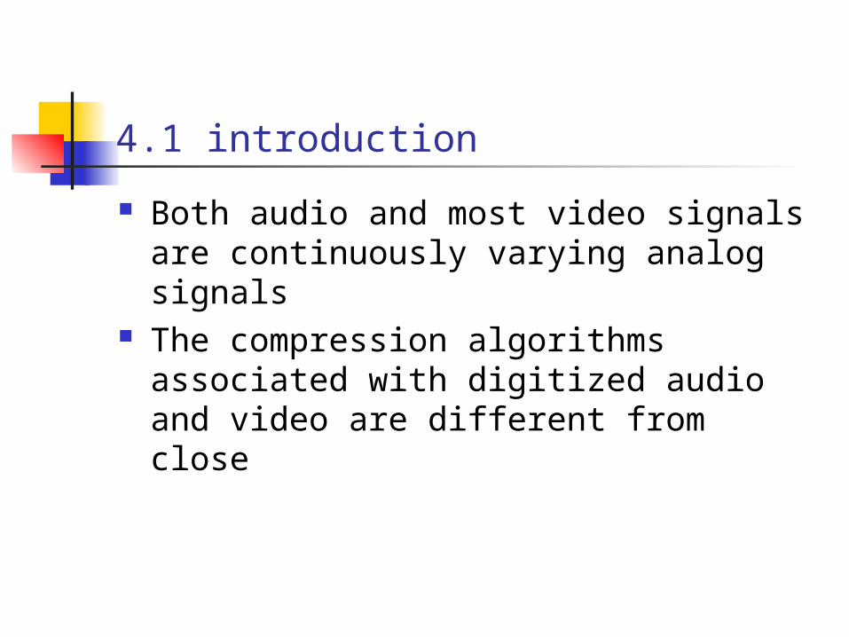
4.1 introduction
Both audio and most video signals are continuously varying analog signals
The compression algorithms associated with digitized audio and video are different from close

4.2 Audio compress Pulse code modulation(PCM) Bandlimited signal The bandwidth of the communication
channels that are available dictate rates that are less than these.This can be achieved in one of two ways: Audio signal is sampled at a lower
rate A compression algorithm is used

4.2.1 Differential pulse code modulation
DPCM is a derivative of standard PCM and exploits the fact that,for most audio signals, the range of the differences in amplitude between successive samples of the audio waveform is less than the range of the actual sample amplitudes.
Figure4.1

4.2.1 Differential pulse code modulation –cont (figure 4.1)

4.2.2 Adaptive differential PCM
Additional savings in bandwidth –or improved quality –can be obtained by varying the number of bits used for the difference signal depending on its amplitude
A second ADPCM standard ,which is G.722.It added subband coding.
A third standard based on ADPCM is also available.this is defined in G.726.This also uses subband coding but with a speech bandwidth of 3.4kHz

4.2.3 Adaptive Predictive Coding(APC)
Even higher levels of compression-but at higher levvels of complexity-can be obtained by also making the predictor coefficients adaptive.This is the principle of adaptive of adaptive predictive coding

4.2.4 Linear predictive coding
There are then quantizized and sent and the destination uses them,together with a sound synthesizer,to regenerate a sound that is perceptually comparable with the source audio signal.this is LPC technique.
Three feature which determine the perception of a signal by the ear are its: Pitch Period Loudness
Basic feature of an LPC encoder/decoder: figure 4.4

4.2.4 Linear predictive coding -cont (figure 4.4)

4.2.5 Code-excited LPC
Code-excited LPC The synthesizers used in most LPC decoders
are based on a very basic model of the vocal tract
In the CELP model,instead of treating each digitized segment independently for encoding purpose
All coders of this type have a delay associated with them which is incurred while each block of digitized samples is analyzed by the encoder and the speech is reconstructed at the decoder

4.2.6 Perceptual coding
Perceptual encoders have been designed for the compression of general audio
Perceptual coding since its role is to exploit a number of the limitation of the human ear.
Sensitivity of the ear A strong signal may reduce the level of
sensitivity of the ear to other signals which are near to it in frequency

4.2.6 Perceptual coding -cont
The Sensitivity of the ear varies with the frequency of the signal,the perception threshold of the ear – that is, its minimum level of sensitivity-as a function of frequency is show in figure 4.5(a)
Most sensitive to signals in the range 2-5kHz
Shown 4.5(b) shows how the the sensitivity of the ear changes in the vicinity of a loud signal

4.2.6 Perceptual coding -cont (figure4.5)

4.2.6 Perceptual coding -cont
The masking effect also varies with frequency as show in figure 4.6
Critical bandwidth Temporal masking:
When the ear hears a loud sound,it takes a short but finite time before it can hear a quieter sound
SHOW 4.7

4.2.6 Perceptual coding-cont (figure4.6)

4.2.6 Perceptual coding-cont (figure4.7)

4.2.7 MPEG AUDIO CODERS
ENCODING Input signal is first sampled and
quantized using PCM The bandwidth that is available for
transmission is divided into a number of frequency subbands using a bank of analysis filters
Scaling factor: THE analysis filter band also determines
the maximum amplitude of the 12 subband samples in each subband

4.2.7 MPEG AUDIO CODERS -cont
Discrete Fourier transform(DFT) The 12 set of 32 PCM samples are first
transformed into an equivalent set of frequency components using a mathematical technique
Signal-to-mask ratios(SMRs) Using the known hearing thresholds and
masking properties of each subband,the model determines the various masking effects of this set of signals

4.2.7 MPEG AUDIO CODERS -cont (figure4.8)
Frame format,show figure 4.8(b)
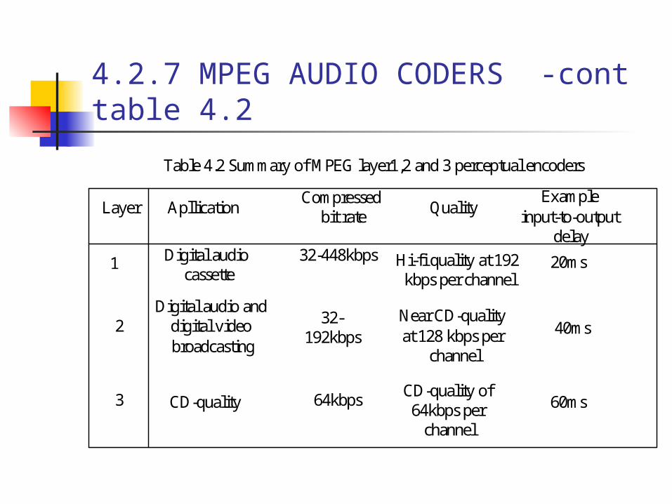
4.2.7 MPEG AUDIO CODERS -cont table 4.2
1
Layer ApllicationCompressed
bit rate QualityExample
input-to-output delay
2
3
Digital audio cassette
Digital audio and digital video broadcasting
CD-quality
32-448kbps
32-192kbps
64kbps
Hi-fi quality at 192 kbps per channel
Near CD-quality at 128 kbps per
channel
CD-quality of 64kbps per
channel
20ms
40ms
60ms
Table 4.2 Summary of MPEG layer1,2 and 3 perceptual encoders

4.2.8 Dolby audio coders
MPEG V.S Dolby AC-1 ,show figure 4.9 MPEG:
Advantage: psychoacoustic model is required only in the encoder
Disadvantage:a significant portion of each encoded frame contains bit allocation information
Dolby AC-1: Use a fixed bit allocation strategy for
each subband which is then used by both the encoder and decoder

4.2.8 Dolby audio coders -cont (figure4.9)

4.2.8 Dolby audio coders -cont
Dolby AC-2 standard which is utilized in many applications including the compression associated with the audio of a number of PC sound cards
The hybrid approach is used in the Dolby AC-3 standard which has been defined for use in a similar range of applications as the MPEG audio standards including the audio associated with advanced television(ATV)

4.3 Video compression
The digitization format defines the sampling rate that is used for the luminance ,Y ,and two chrominance,Cb and Cr

4.3.1 video compress principles
Frame type I-frame:
I-frames are encoded without reference to any other frames
GOP:The number of frame between I-frames
P-frame: encoding of a p-frame is relative to the
contents of either a preceding I-frame or a preceding P-frame

4.3.1 video compress principles -cont
The number of P-frames between I-frame is limited since any errors present in the first P-frame will be propagated to the next
B-frame:their contents are predicted using search regions in both past and future frames
PB-frame:this does not refer to a new frame type as such but rather the way two neighboring P- and B-frame are encoded as if they were a single frame
D-frame:only used in a specific type of application. It has been defined for use in movie/video-on-demand application

4.3.1 video compress principles –cont (figure4.11)

4.3.1 video compress principles -cont
Motion estimation and compensation P-frame Macroblock structure ,show figure
4.12(a) P-frame Encoding procedure,show figure
4.12(b) Best match macroblock Motion vector DCT+ Quantization +run-length & V Huffman
B-frame encoding procedure,show figure 4.13

4.3.1 video compress principles –cont (figure4.12)

4.3.1 video compress principles –cont (figure4.13)

4.3.1 video compress principles –cont (figure4.14)
Implementation issues ,show figure4.14

4.3.1 video compress principles –cont
Performance - Compression ratio I-frame:10:1 – 20:1 P-frame:20:1-30:1 B-frame:30:1-50:1

4.3.2 H.261
For the provision of video telephony and videoconferencing services over an ISDN
Transmission channels multiples of 64kbps Digitization format used is either the
common intermediate format(CIF) or the quarter CIF(QCIF) CIF:Y=352X288, Cb=Cr=176X144 QCIF:Y=176X144, Cb=Cr=88X72
H.261 encoding format show figure 4.15

4.3.2 H.261 -cont

4.3.2 H.261 -cont
H.261 video encoder principles figure 4.16(a)

4.3.2 H.261 -cont
Two threshold Low high

4.3.3 H.263
Over wireless and public switched telephone networks(PSTN)
Include video telephony videoconferencing , security surveillance ,interactive game
Low bit rates Digitization formats
QCIF:Y=176X144 , Cb=Cr=88X72 S-QCIF:Y=128X96, Cb=Cr=64X68

4.3.3 H.263 -cont
Frame types: I-frame P-frame B-frame PB-frame:because of the much reduced
encoding overhead Unrestricted motion vectors
To overcome this limitation ,for those pixels of a potential close-match macroblock that fall outsize of the frame boundary

4.3.3 H.263 -cont
Error resilience Cause error propagation,show figure4.17(a) Error tracking and resilience,show
figure4.17(b) When an error is detected , decoder send
NAK to encoder Independent segment decoding
Prevent these errors from affecting neighboring GOBs in succeeding frames
Show figure 4.18

4.3.3 H.263 -cont (figure 4.17)

4.3.3 H.263 -cont (figure 4.18)

4.3.3 H.263 -cont (figure 4.19)
Reference picture selection(figure 4.19 ) NAK mode ,show figure 4.19(a) ACK mode,show figure 4.19(b)

4.3.4 MPEG
MPEG-1 Source intermediate digitization format(SIF) Resolution:352X288 VHS-quality audio Video on CD-ROM at bit rates up to 1.5Mbps
MPEG-2 Four level
LOW MAIN High 1440 high

4.3.4 MPEG -cont
MPEG-4 Similar h.163 Low bit rate range from 4.8 to 64kbps Interactive multimedia application

4.3.5 MPEG-1
Support two type spatial resolutions NTSC PAL
Frame type:I,P,B-frame,(figure 4.20) Based on the h.261,there are two main
differences: Temporal B-frame was increased
Video bitstream structure (figure 4.21)

4.3.5 MPEG-1 -cont (figure 4.20)
Figure 4.20

4.3.5 MPEG-1 -cont (figure 4.21)

4.3.6 MPEG-2
Support four levels and five profiles MP@ML
For digital television broadcasting Resolution of either 720X480 pixels at 30Hz
or 720X576 pixels at 25Hz Bit rate from 4Mbps – 15Mbps Use interlaced scanning,show 4.22(a) Field mode(figure 4.22(b)) Frame mode(figure 4.22(c))

4.3.6 MPEG-2 -cont (figure4.22)

4.3.6 MPEG-2 -cont
HDTV(Grand Alliance) ITU-R HDTV
16/9 ASPECT RATIO MP@HL Audio: Dolby AC-3
DVB HDTV 4/3 ASPECT RATIO SSP@H1440-SPATIALLY-SCALEABLE
PROFILE AT HIGH 1440 MPEG audio layer 2

4.3.7 MPEG-4
Scene composition Content-based functionalities Audio-visual object(AVOs) Object descriptor Binary format for scenes Scene descriptor Video object planes(VOPs)(figure 4.23)
Audio and video compression(figure 4.24)

4.3.7 MPEG-4 -cont (figure4.23)

4.3.7 MPEG-4 -cont (figure4.24)

4.3.7 MPEG-4 -cont
Transmission format(figure 4.25) Transport stream Packetized elementary Elementary stream(ES) FlexMux layer Synchronization layer Elementary stream descriptor(ESD) Composition and rendering block
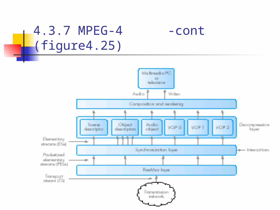
4.3.7 MPEG-4 -cont (figure4.25)

4.3.7 MPEG-4 -cont
Error resilience techniques (figure 4.26) Use of fixed-length Based on reversible VLCs Error occur
macroblock header

4.3.7 MPEG-4 -cont (figure4.26)

4.3.7 MPEG-4 -cont
Reversible VLCs (figure 4.27) The associated set of RVLCs is then
produced by adding a fixed—length prefix and suffix to each of the corresponding VLCs
Forward direction scan Reverse direction scan The error at difference points in the
bitstream resulting in an overlap region

4.3.7 MPEG-4 -cont (figure4.27)