Unit 16 BASIC ELECTRONICS - ilmkidunya.com
16
• explain the process of thermionic emission emitted from a filament. • describe the simple construction and use of an electron gun as a source of electron beam. • describe the effect of electric field on an electron beam. • describe the effect of magnetic field on an electron beam. • describe the basic principle of CRO and make a list of its uses. • differentiate between analogue and digital electronics. • state the basic operations of digital electronics. • identify and draw the symbols for the logic gates (NOT, OR, AND, NOR and NAND). • state the action of the logic gates in truth table form. • describe the simple uses of logic gates. Unit 16 Unit 16 Unit 16 BASIC ELECTRONICS BASIC ELECTRONICS BASIC ELECTRONICS After this students will be able to: studying unit, • • identify by quoting examples that the modern world is the world of digital electronics. Science, Technology and Society Connections identify that the computers are the forefront of electronic technology. • realize that electronics is shifting from low-tech electrical appliances to high-tech electronic appliances. The students will be able to:
Transcript of Unit 16 BASIC ELECTRONICS - ilmkidunya.com

• explain the process of thermionic emission emitted from a filament. • describe the simple construction and use of an electron gun as a source of
electron beam. • describe the effect of electric field on an electron beam. • describe the effect of magnetic field on an electron beam. • describe the basic principle of CRO and make a list of its uses. • differentiate between analogue and digital electronics. • state the basic operations of digital electronics. • identify and draw the symbols for the logic gates (NOT, OR, AND, NOR and
NAND). • state the action of the logic gates in truth table form. • describe the simple uses of logic gates.
Unit 16Unit 16Unit 16
BASIC ELECTRONICS BASIC ELECTRONICS BASIC ELECTRONICS After this students will be able to:studying unit,
•
•
identify by quoting examples that the modern world is the world of digital electronics.
Science, Technology and Society Connections
identify that the computers are the forefront of electronic technology.
• realize that electronics is shifting from low-tech electrical appliances to high-tech electronic appliances.
The students will be able to:
BASIC ELECTRONICS
For your information
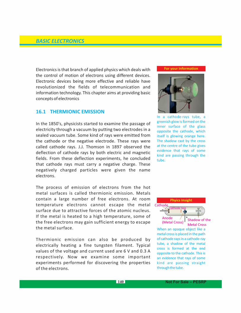
In a cathode-rays tube, a greenish glow is formed on the inner surface of the glass opposite the cathode, which itself is glowing orange here. The shadow cast by the cross at the centre of the tube gives evidence that rays of some kind are passing through the tube.
Electronics is that branch of applied physics which deals with the control of motion of electrons using different devices. Electronic devices being more effective and reliable have revolutionized the fields of telecommunication and information technology. This chapter aims at providing basic concepts of electronics
16.1 THERMIONIC EMISSION
In the 1850's, physicists started to examine the passage of electricity through a vacuum by putting two electrodes in a sealed vacuum tube. Some kind of rays were emitted from the cathode or the negative electrode. These rays were called cathode rays. J.J. Thomson in 1897 observed the deflection of cathode rays by both electric and magnetic fields. From these deflection experiments, he concluded that cathode rays must carry a negative charge. These negatively charged particles were given the name electrons.
The process of emission of electrons from the hot metal surfaces is called thermionic emission. Metals contain a large number of free electrons. At room temperature electrons cannot escape the metal surface due to attractive forces of the atomic nucleus. If the metal is heated to a high temperature, some of the free electrons may gain sufficient energy to escape the metal surface.
Thermionic emission can also be produced by electrically heating a fine tungsten filament. Typical values of the voltage and current used are 6 V and 0.3 A respectively. Now we examine some important experiments performed for discovering the properties of the electrons.
Phyics Insight
When an opaque object like a metal cross is placed in the path of cathode rays in a cathode-ray tube, a shadow of the metal cross is formed at the end opposite to the cathode. This is an evidence that rays of some kind are passing straight through the tube.
140
Cathode
Anode(Metal Cross)
Shadow of the Metal Cross
Not For Sale – PESRP
Cathode rays

High Voltage supply
Electron beam
Anode
Heated filament
Filamentsupply V
Emitting electrons
V
e ee
- --e
e
e
e
-
-
--
+
+–
+–
16.2 INVESTIGATING THE PROPERTIES OF ELECTRONSAn electron gun (Fig. 16.1) is used to investigate the properties of electron beam. The electrons are produced by thermionic emission from a tungsten filament heated by 6 V supply. A high positive potential (several thousands) is applied to a cylindrical anode (+). The electrons are accelerated to a high speed and pass through the hole of the anode in the form of a fine beam of electrons. The whole set up is fitted in an evacuated glass bulb.
Fig. 16.1: Electron gun
Deflection of electrons by electric fieldWe can set up electric field by applying a potential difference across two parallel metal plates placed horizontally separated by some distance. When an electron beam passes between the two plates, it can be seen that the electrons are deflected towards the positive plate (Fig.16.2). The reason for this is that electrons are attracted by the positive charges and are repelled by the negative charges due to force F=qE, where ‘q’ is the electron charge and E is the electric field due to plates. The degree of deflection of electrons from their original direction is proportional to the strength of the electric field applied.
Deflection of electrons by magnetic fieldNow we apply magnetic field at right angle to the beam of electrons by using a horseshoe magnet (Fig. 16.3). We will
141
Fig 16.2: Deflection of cathode rays by an electric field
Fig.16.3: Deflection of cathode rays by a fieldmagnetic
BASIC ELECTRONICS
P
P
+Q
+
1
2
AK
S
KA
+
Not For Sale – PESRP
– Q
–

notice that the spot of the electrons beam on the screen is getting deflected from its original direction. Now change the direction of the horseshoe magnet. We will see that spot on the fluorescent screen is getting deflected in the opposite direction.
16.3 CATHODE-RAY OSCILLOSCOPE (C.R.O)
The cathode-ray oscilloscope is an instrument which is used to display the magnitudes of changing electric currents or potentials (Fig. 16.4). The information is displayed on the screen of a “cathode-ray tube”. This screen appears as a circular or rectangular window usually with a centimetre graph superimposed on it. For example, the picture tube in our TV set and the display terminal of most computers are cathode-ray tubes.
Fig. 16.4: Cathode-Ray Oscilloscope
The cathode-ray oscilloscope (C.R.O) consists of the following components:
The electron gun with control grid
The deflecting plates
A fluorescent screen
The Electron GunThe electron gun consists of an electron source which is an electrically heated cathode that ejects electrons. Electron gun also has an electrode called grid G for controlling the flow of electrons in the beam. The grid is connected to a negative potential. The more negative this potential, the more
142
Point to ponder!When a magnet is brought near to the screen of a television tube, picture on the screen is distorted. Do you know why?
Do you know?
Electromagnets are used to deflect electrons to desired positions on the screen of a television tube.
A cathode ray will deflect as shown when it is under the influence of an external magnetic field.
Path ofbeam
Screen
Electromagnets
TVtube
BASIC ELECTRONICS
Not For Sale – PESRP
Fluorescentscreen
Deflecting systemElectron gun
HeaterCathode
Acceleratingand focusing anodes
Plates for verticaldeflection
Plates for horizontaldeflection
6V F
G
Y X
X
SpotY X
Electrongun

electrons will be repelled from the grid and hence fewer electrons will reach the anode and the screen. The number of electrons reaching the screen determines the brightness of the screen. Hence, the negative potential of the grid can be used as a brightness control. The anode is connected to positive potential and hence is used to accelerate the electrons. The electrons are focused into a fine beam as they pass through the anode.The Deflecting Plates
After leaving the electron gun, the electron beam passes between a pair of horizontal plates. A potential difference applied between these plates deflects the beam in a vertical plane. This pair of plates provides the Y-axis or vertical movement of the spot on the screen. A pair of vertical plates provides the X-axis or horizontal movement of the spot on the screen.
The Fluorescent Screen
The screen of a cathode-ray tube consists of a thin layer of phosphor, which is a material that gives light as a result of bombardment by fast moving electrons. The CRO is used in many fields of science; displaying waveforms, measuring voltages, range-finding (as in radar), echo-sounding (to find the depth of seabeds). The CRO is also used to display heartbeats.
16.4 ANALOGUE AND DIGITAL ELECTRONICS
The quantities whose values vary continuously or remain constant are known as analogue quantities. For example, the temperature of air varies in a continuous fashion during 24 hours of a day. If we plot a graph between time and temperature recorded at different times, we get a graph (Fig.16.5-a). This graph shows that temperature varies continuously with time. Therefore, we say that temperature is an analogue quantity. Similarly, time, pressure, distance, etc. are analogue quantities.
143
Do you know?
The glow in the tube is due to circular motion of electron in the magnetic field. The glow comes from the light emitted from the excitations of the gas atoms in the tube.
Do you know?Cathode Rays The beam of electrons was called a cathode ray, because the electron had not yet been d i s c o v e r e d . T h e o l d terminology survives in electronic engineering where a cathode-ray tube is any tube constructed along Thomson’s lines whether in a computer monitor, a television, or an oscilloscope.
BASIC ELECTRONICS
Not For Sale – PESRP
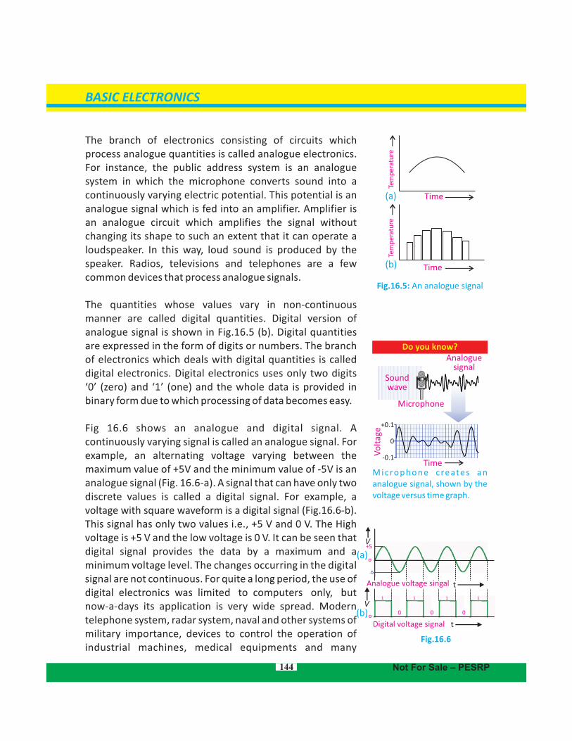
The branch of electronics consisting of circuits which process analogue quantities is called analogue electronics. For instance, the public address system is an analogue system in which the microphone converts sound into a continuously varying electric potential. This potential is an analogue signal which is fed into an amplifier. Amplifier is an analogue circuit which amplifies the signal without changing its shape to such an extent that it can operate a loudspeaker. In this way, loud sound is produced by the speaker. Radios, televisions and telephones are a few common devices that process analogue signals.
The quantities whose values vary in non-continuous manner are called digital quantities. Digital version of analogue signal is shown in Fig.16.5 (b). Digital quantities are expressed in the form of digits or numbers. The branch of electronics which deals with digital quantities is called digital electronics. Digital electronics uses only two digits ‘0’ (zero) and ‘1’ (one) and the whole data is provided in binary form due to which processing of data becomes easy.
Fig 16.6 shows an analogue and digital signal. A continuously varying signal is called an analogue signal. For example, an alternating voltage varying between the maximum value of +5V and the minimum value of -5V is an analogue signal (Fig. 16.6-a). A signal that can have only two discrete values is called a digital signal. For example, a voltage with square waveform is a digital signal (Fig.16.6-b). This signal has only two values i.e., +5 V and 0 V. The High voltage is +5 V and the low voltage is 0 V. It can be seen that digital signal provides the data by a maximum and a minimum voltage level. The changes occurring in the digital signal are not continuous. For quite a long period, the use of digital electronics was limited to computers only, but . . .now-a-days its application is very wide spread. Modern telephone system, radar system, naval and other systems of military importance, devices to control the operation of industrial machines, medical equipments and many
144
Fig.16.6
Digital voltage signal to
o
+5
tAnalogue voltage singal
(a)
(b) 0 0 0
Fig.16.5: An analogue signal
Time
Tem
per
atu
re
(a)
(b)
BASIC ELECTRONICS
Not For Sale – PESRP
1 1 1 1
Time
Do you know?
Microphone c reates an analogue signal, shown by the voltage versus time graph.
Analoguesignal
Soundwave
Microphone
Time
Vo
ltag
e
+0.1
0
-0.1
Tem
per
atu
re
V
V

household appliances are using digital technology.
In our daily life, the quantities that we perceive by our senses are usually analogue quantities which cannot be processed by digital circuits. To overcome this problem, a special circuit has been designed which converts in binary form the analogue signal into a digital one in the form of digits in binary form. This circuit is known as analogue to digital converter (ADC). This binary output is then processed by a computer which also gives output in digital form. The output of the computer is again converted into an analogue form by a circuit known as digital to analogue converter (DAC). As the output of DAC is an analogue signal, it can be readily sensed by us. Thus, electronic systems used at present consist of both analogue and digital type circuits.
16.5 B A S I C O P E R AT I O N S O F D I G I TA L ELECTRONICS – LOGIC GATES
A switch has only two possible states. It could be either open or closed. Similarly, a given statement would be either true or false. Such things which can have only two possible states are known as binary variables. The states of variables are binaryusually represented by the digits ‘0’ and ‘1’.
Suppose we form a circuit by connecting a lamp to a battery using a switch S (Fig. 16.7). We call state of switch as input and state of current or lamp as output. When the switch is open no current passes through the circuit and lamp is OFF. In other words, when input is zero output is also zero. When the switch is closed current passes through the circuit and lamp is ON. Thus, the output current is also a binary variable. In case, the current is passing, we can say the value of the output is ‘1’ and it is ‘0’ when no current is passing. The possible combinations of input and output states of this circuit are shown in Table 16.1.
These states are also called logic states or logic variables. Now the question arises that if the values of input variables of
BASIC ELECTRONICS
Not For Sale – PESRP
For your informationDigital technology has entered every part of our lives. Digital TV gives excellent view and allows us to be interactive.Digital cameras are fast replacing traditional film equipment. We can download an image into a PC and crop, enhance, airbrush and edit the picture. Smart ID cards are being developed. A single card can be a passport, national insurance card and driving license all in one. The card could also hold biometric data like an eye retina scan and v o i c e s c a n f o r u n i q u e identification and security. All of this data would be held digitally in the tiny chip.
Fig. 16.7
V+-
Table 16.1
S
Lamp
S
Open
Closed
OFF
ON
Lamp
145

a circuit or a system are known, then how can we determine the value of output? To answer this question, George Boole invented a special algebra called Boolean algebra also known as algebra of logics. It is a branch of mathematics which deals with the relationships of logic variables. Instead of variables that represent numerical quantities as in conventional algebra, Boolean algebra handles variables that represent two types of logic propositions; 'true' and 'false'.
Boolean algebra has become the main cornerstone of digital electronics. It operates with two logic states, '1' and '0', represented by two distinct voltage levels. Boolean algebra's simple interpretation of logical operators AND, OR, and NOT has allowed the systematic development of complex digital systems. These include simple logic gates that perform simple mathematical as well as intricate logical operations. Logic operations may be thought of as a combination of switches.
Since a logic gate is a switching circuit (i.e., a digital circuit), its outputs can have only one of the two possible states. either a high voltage ‘1’ or a low voltage ‘0’ - it is either ON or OFF. Whether the output voltage of logic gate is high ‘1’ or low ‘0’ will depend upon the condition at its input. Now we discuss some basic logic operations and logic gates that implement these logic operations.
16.6 AND OPERATION
In order to understand the logic AND operation see the Fig 16.8 in which a lamp is connected to a battery using two switches S and S connected in series considered as two 1 2
inputs. There are four possible states of these two switches which are given below:
(i) When S and S are both open, the lamp is OFF.1 2
(ii) When S is open but S closed, the lamp is OFF.1 2
(iii) When S is closed but S open, the lamp is OFF.1 2
(iv) When both S AND S are closed, the lamp is ON. 1 2
146
Introduction to Boolean Algebra
The algebra used to describe logic operations by symbols is called Boolean Algebra. Like ordinary algebra, English alphabets (A, B, C, etc.) are used to represent the Boolean variables. However, Boolean variable can have only two values; 0 and 1. Digital circuits perform the binary arithmetic operations with binary digits ‘1’ and ‘0’. These operations are called logic function or logical operations.
Fig. 16.8
BASIC ELECTRONICS
S S1 2
LampV
+
–
Not For Sale – PESRP
Do you know?TV and telephone signals once travelled as analogue signals. Electrical signals in copper wires would interfere with each other and give poor quality sound and vision. Today, everything is going digital. The big advantage of digital is quality. There is no interference or loss of strength in digital signal travelling in an optical fibre.

The four possible combinations of switches S and S are 1 2
shown in the Table 16.2. It is clear that when either of the switches (S or S ) or both are open, the lamp is OFF. When 1 2
both switches are closed, the lamp is ON. Symbol for AND operation is dot (.). Its Boolean expression is: X = A . B and is read as “ X equals A AND B”.Set of inputs and outputs in binary form is called truth table. In binary language, when either of the inputs or both the inputs are low (0), the output is low (0). When both the inputs are high (1), the output is high (1). The truth table of AND operation is shown in Table 16.3, where X represents the output. Therefore, AND operation may be represented by switches connected in series, with each switch representing an input. When two switches are closed i.e., the inputs of the AND operation are at logic '1', the output of the AND operation will be at logic '1'. But when two switches are open i.e., the inputs of AND operation are at logic '0', the output of AND operation will be at logic '0'. For any other state of two switches (i.e., the input of AND operation), the output will be '0'.
Fig. 16.9
The circuit which implements the AND operation is known as AND gate. Its symbol is shown in Fig. 16.9. AND gate has two or more inputs and only one output. The value of output of AND gate is always in accordance with the truth table of AND operation. It means output of AND gate will be '1' only when all of its inputs are at logic '1', and for all other situations output of AND gate will be '0'.
16.7 OR OPERATION
In order to understand the logic OR operation see the circuit shown in Fig.16.10. A lamp is connected to a battery using two switches S and S connected in parallel considered as 1 2
147
Table 16.2
Table 16.3
A B
X = A.B
0 0 1 1
0 1 0 1
0 0 0 1
BASIC ELECTRONICS
S 1 S 2 Lamp
Open
Open
Closed
Closed
Open
Closed
Open
Closed
OFF
OFF
OFF
ON
Not For Sale – PESRP
AND gate
A
B
X =A.B

two inputs. There are four possible states of these two switches which are given below:(i) When S and S are open, the lamp is OFF.1 2
(ii) When S is open and S closed, the lamp is ON.1 2
(iii) When S is closed and S open, the lamp is ON1 2
(iv) When both S and S are closed, the lamp is ON. 1 2
As evident from the circuit in Fig. 16.10, the lamp will glow if at least one of the switches is closed. In the language of Boolean algebra, we say the lamp will glow at least one of the values of S and S is at logic '1'. 1 2
Table 16.4 describes all possible states of the switches for the 'OR' operation. OR operation is represented by the symbol of plus (+). Boolean expression for OR operation is : X = A + B and is read as “ X equals A OR B”. Truth table of OR operation is shown in Table 16.5. An OR operation may be represented by switches connected in parallel, since only one of these parallel switches need to turn on in order to flow current in the circuit.
= A + B
Fig.16.11
The electronic circuit which implements the OR operation is known as OR gate. Symbolically, OR gate is shown in Fig. 16.11. It has two or more inputs and has only one output. The values of output of OR gate are always in accordance with the truth table of OR operation. It means, the value of output of OR gate will be '1' when anyone of its inputs is at '1'. The output will be '0', when all inputs are at '0'.
16.8 NOT OPERATION
In order to understand NOT operation, see the circuit shown in Fig. 16.12. A lamp is connected to a battery with a switch S, in parallel When the switch is open, current will pass through the lamp and it will glow. When switch is closed, no current
148
Fig. 16.10
Lamp
1
2
BASIC ELECTRONICS
Table 16.4
S1 S2 Lamp
Open
Open
Closed
Closed
Open
Closed
Open
Closed
OFF
ON
ON
ON
Table 16.5
Not For Sale – PESRP
A B X = A+B
0 0 0
0 1 1
1 0 1
1 1 1
OR gate
V+-
S
S
A B X = A+B
X

A
NOT gate
X
will pass through the lamp due to large resistance of its filament and it will not glow. States of the switch and the lamp are shown in Table 16.6.NOT operation is represented by a line or bar over the symbol i.e., X = A and is read as “X equals A NOT ”. It means NOT operation changes the state of a Boolean variable. For example, if the value of a Boolean variable is 1, then after NOT operation its value would change to ‘0’. Similarly, if its value before NOT operation is 0, then after NOT operation it would change to ‘1’. Thus NOT operation inverts the state of Boolean variable. Truth table of NOT operation is given in Table 16.7. The electronic circuit which implements NOT operation is known as NOT gate. Symbol of NOT gate is shown in Fig. 16.13. It has only one input and one output terminal. NOT gate works in such a way that if its input is 0, its output would be ‘1’. Similarly, if its input is ‘1’, then output would be ‘0’.
= A
Fig. 16.13
NOT gate performs the basic logical function called inversion or complementation. NOT gate is also called inverter. The purpose of this gate is to convert one logic level into the opposite logic level. When a HIGH level is applied to an inverter, a LOW level appears on its output and vice versa.
16.9 NAND GATE
NAND operation is simply an AND operation followed by a NOT operation. For example, NAND gate is obtained by coupling a NOT gate with the output terminal of the AND gate (Fig. 16.14-a).
Fig.16.14
149
Fig. 16.12
Table 16.6
Table 16.7
BASIC ELECTRONICS
Not For Sale – PESRP
= A . B
X = A
1
0
-+
S
Lamp
S
Open
Closed
ON
OFF
Lamp
A
0
1
X
NAND gate
A
BX = A.BA.B
NOTAND
AB
(a) (b)

= A + B
The NOT gate inverts the output of the AND gate. The output of the NAND equals A . B and is written as X = A . B. It is read as X equals A AND B NOT. Symbol of NAND gate is shown in Fig. 16.14-b. As shown in the figure, the NOT gate has been replaced with a small circle. In the symbol of NAND gate, this small circle attached at the output of NAND gate given NOT operation. Truth table of NAND gate is given in Table 16.8.
16.10 NOR GATE
The NOR operation is simply an OR operation followed by a NOT operation. The NOR gate is obtained by coupling the output of the OR gate with the NOT gate (Fig.16.15-a). Thus, for the same combination of inputs, the output of a NOR gate will be opposite to that of an OR gate. Its Boolean expression is X = A + B. It is read as X equals A OR B NOT. Symbol of NOR gate is shown in Fig. 16.15(b). Table 16.9 is the truth table of NOR gate.
Fig. 16.15
16.11 USES OF LOGIC GATES
We can use logic gates in electronic circuits to do useful tasks. These circuits usually use light depending resistors (LDRs) to keep inputs LOW. An LDR can act as a switch that is closed when illuminated by light and open in the dark.
House Safety Alarm
We can use single NAND gate to make burglar alarm. This can be done by using NAND gate, an LDR, a push-button switch S and an alarm (Fig. 16.16). Connect LDR between NAND gate
150
For your information
Formation of NOT gate from NAND and NOR gates with the resultant truth tables.
BASIC ELECTRONICS
For your information
Here double line indicates double NOT operation.
Table 16.8
Table 16.9
Not For Sale – PESRP
A AA A
A
0
0
1
1
B
0
1
0
1
X = A.B
1
1
1
0
A
0
0
1
1
B
0
1
0
1
X = A+B
1
0
0
0
X = A = A
X = A + B = A + B
X = A.B = A.B
X
NOR gate
A
BX = A+BA+B
NOTOR
AB
(a) (b)

input B and the positive terminal of the battery. The LDR will cause a HIGH level input ‘1’ at B when in light because of its Low resistance. The LDR will cause a Low level input ‘0’ at B when light is interrupted and causes high resistance in LDR. A LOW level signal is also caused at A when burglar steps on switch S. So this burglar alarm sounds when either burglar interrupts light falling on LDR or steps on switch S.
Fig. 16.16: Burglar alarm schematic circuit
151
Quick Quiz
Assume you have an OR gate with two inputs, A and B. Determine the output, C, for the following cases:
(a) A = 1, B = 0
(b) A = 0, B = 1 If either input is one, what is the output?
For your information
Most of today's technologies fall under the classification of digital electronics.
Digital electronics devices sto re a n d p ro c e s s b i t s electronically. A bit represents data using 1's and 0's. Eight bits is a byte – the standard grouping in digital electronics.
Digitization is the process of transforming information into 1's and 0's.
Alarm
LDR
R
+
–
S
R
A
B
BASIC ELECTRONICS
Not For Sale – PESRP

152
SUMMARY Electronics is that branch of applied physics which deals with the control of motion
of electrons in different devices for various useful purposes.
The process of emission of electrons from the surface of hot metal is called thermionic emission.
Cathode rays are electrons which are emitted from the hot surface of cathode and travel towards anode due to potential difference.
Beam of electrons emitted from cathode surface can be deflected by electric and magnetic fields.
The cathode-ray oscilloscope is an instrument which can be used to display the magnitudes of rapidly changing electric current or potential. It consists of the following three parts: the electron gun, the deflecting plate and a fluorescent screen.
Those quantities which change continuously with time are known as analogue quantities. And the quantities which change in discrete steps are called digital quantities.
Electronic devices have become integral part of our daily lives. Television, computers, cell phone, audio and video cassette recorders and players, radio, hi-fi sound system have made our lives more comfortable and pleasant.
The branch of electronics which processes the data being provided in the form of analogue quantities is called analogue electronics.
The branch of electronics which processes the data being provided in the form of digits is known as digital electronics.
Logic gates are the circuits which implement the various logic operations. These are digital circuits which have one or more inputs but only one output.
There are three basics logic gates: AND gate, OR gate and NOT gate. While NAND gate and NOR gate are combinations of these basic gates.
The AND gate is a logic gate that gives an output of '1' only when all of its inputs are '1'. The OR gate is a logic gate that gives an output of '0' only when all of its inputs are '0'. The NOT gate is a logic gate that gives an output that is opposite to the state of its input.
The truth tables are tables which give the values of the inputs and outputs of the basic types of logic gates or combination of such gates.
MULTIPLE CHOICE QUESTIONS Choose the correct answer from the following choices:
i. The process by which electrons are emitted by a hot metal surface is known as (a) boiling b) evaporation (( (c) conduction d) thermionic emission
BASIC ELECTRONICS
Not For Sale – PESRP

153
ii. The particles emitted from a hot cathode surface are ( (a) positive ions b) negative ions (c) ( protons d) electrons
iii. The logical operation performed by this gate is
( (a) AND b) NOR ( (c) NAND d) OR
iv. AND gate can be formed by using two( (a) NOT gates b) OR gates ( (c) NOR gates d) NAND gates
v. The output of a two-input NOR gate is 1 when:( (a) A is ‘1’ and B is ‘0’ b) A is ‘0’ and B is ‘1’( (c) both A and B are ‘0’ d) both A and B are ‘1’
vi. If X = A.B, then X is ‘1’ when:( (a) A and B are ‘1’ b) A or B is ‘0’ ( (c) A is ‘0’ and B is ‘1’ d) A is ‘1’ and B is ‘0’
vii. The output of a NAND gate is ‘0’ when( (a) both of its inputs are ‘0’ b) both of its inputs are ‘1’ ( (c) any of its inputs is ‘0’ d) any of its inputs is ‘1’
REVIEW QUESTIONS16.1. Describe, using one simple diagram in each case, what happens when a narrow beam of electrons is passed through (a) a uniform electric field (b) a uniform magnetic field. What do these results indicate about the charge on electron?16.2. Explain the working of different parts of oscilloscope. 16.3. Name some uses of oscilloscope.16.4. Considering an oscilloscope explain: (i) How the filament is heated? (ii) Why the filament is heated? (iii) Why the anode potential is kept positive with respect to the cathode potential? (iv) Why a large potential is applied between anode and cathode? (v) Why the tube is evacuated?16.5. What is electron gun? Describe the process of thermionic emission. 16.6. What do you understand by digital and analogue quantities? 16.7. Differentiate between analogue electronics and digital electronics. Write down names of five analogue and five digital devices that are commonly used in
BASIC ELECTRONICS
Not For Sale – PESRP
A
BX

154
everyday life.16.8. State and explain for each case whether the information given by the following devices is in analogue or a digital form. a. a moving-coil voltmeter measuring the e.m.f of a cell. b. a microphone generating an electric current. c. a central heating thermostat controlling the water pump. d. automatic traffic lights controlling the flow of traffic.16.9. Write down some benefits of using digital electronics over analogue electronics.16.10. What are the three universal Logic Gates? Give their symbols and truth tables.
CONCEPTUAL QUESTIONS16.1. Name two factors which can enhance thermionic emission.16.2. Give three reasons to support the evidence that cathode rays are negatively charged electrons. 16.3. When electrons pass through two parallel plates having opposite charges, they are deflected towards the positively charged plate. What important characteristic of the electron can be inferred from this?16.4. When a moving electron enters the magnetic field, it is deflected from its straight path. Name two factors which can enhance electron deflection.16.5. How can you compare the logic operation X=A.B with usual operation of multiplication?16.6. NAND gate is the reciprocal of AND gate. Discuss16.7. Show that the circuit given below acts as OR gate.
16.8. Show that the circuit given below acts as AND gate.
BASIC ELECTRONICS
Not For Sale – PESRP
A
B
A
B
Y
Y