Unit 10 Automatic Identification - NUI Galway · List advantages of Radio Frequency Identification...
21
Unit 10 Automatic Identification 10.1 Unit Introduction 10.2 Unit Objectives 10.3 Overview of Automatic Identification Methods 10.4 Barcode Technology 10.5 Two-Dimensional Bar Codes 10.6 Radio Frequency Identification 10.7 Other AIDC Technologies 10.8 Case Study 10.9 Unit Review 10.10 Self Assessment 10.11 Self Assessment Answers 10.1 Unit Introduction Automatic identification and data capture (AIDC) is the use of technology to provide direct data entry to a computer, or other micro-processor controlled system, without resorting to manual methods of data-entry. Data collection and retention has increasingly been automated to the point where AIDC systems can operate without relying upon human operators for basic data identification and capture. The following applications are regularly operated in AIDC mode: material handling, storage, sorting, order picking, kitting of parts for assembly; monitoring work order status, work-in-process, machine utilisation, worker attendance, and other measures of factory operation and performance. KEYPOINT Automatic identification and data capture (AIDC) is the use of technology to provide direct data entry to a computer. END KEYPOINT The alternative to AIDC is manual data collection and retention; this suffers from higher rates of error, greater requirements on time, and higher labour costs than AIDC. This unit investigates AIDC with a primary emphasis on bar code technology and radio frequency identification (RFID). Other AIDC technologies, including magnetic stripes, optical character recognition, and machine vision 10.2 Unit Learning Objectives After completing this unit you will be able to: BULLET LIST Identify the concept of Automatic Identification and Data Capture Specify the types of barcode technology that can be identified
Transcript of Unit 10 Automatic Identification - NUI Galway · List advantages of Radio Frequency Identification...

Unit 10 Automatic Identification 10.1 Unit Introduction 10.2 Unit Objectives 10.3 Overview of Automatic Identification Methods 10.4 Barcode Technology 10.5 Two-Dimensional Bar Codes 10.6 Radio Frequency Identification 10.7 Other AIDC Technologies 10.8 Case Study 10.9 Unit Review 10.10 Self Assessment 10.11 Self Assessment Answers 10.1 Unit Introduction Automatic identification and data capture (AIDC) is the use of technology to provide direct data entry to a computer, or other micro-processor controlled system, without resorting to manual methods of data-entry. Data collection and retention has increasingly been automated to the point where AIDC systems can operate without relying upon human operators for basic data identification and capture. The following applications are regularly operated in AIDC mode: material handling, storage, sorting, order picking, kitting of parts for assembly; monitoring work order status, work-in-process, machine utilisation, worker attendance, and other measures of factory operation and performance. KEYPOINT Automatic identification and data capture (AIDC) is the use of technology to provide direct data entry to a computer. END KEYPOINT The alternative to AIDC is manual data collection and retention; this suffers from higher rates of error, greater requirements on time, and higher labour costs than AIDC. This unit investigates AIDC with a primary emphasis on bar code technology and radio frequency identification (RFID). Other AIDC technologies, including magnetic stripes, optical character recognition, and machine vision 10.2 Unit Learning Objectives After completing this unit you will be able to: BULLET LIST Identify the concept of Automatic Identification and Data Capture Specify the types of barcode technology that can be identified

Name the major barcode standard that informs the use of barcodes made by most of contemporary industry Outline the two basic types of two-dimensional barcodes List advantages of Radio Frequency Identification (RFID) technology Identify the principal elements of an RFID system Explain how RFID middleware acts in the RFID system List other AIDC technologies ENDLIST 10.3 Overview of Automatic Identification Methods There are three specific components that comprise technologies for Automatic Identification and Data Capture (AIDC) (see Figure 10.1); these are: NUMLIST Data encoder—data must be coded into a machine-readable format compatible to the requirements of AIDC. A label or tag containing the encoded data is attached to the item to be identified Machine reader or scanner—this is used to read the encoded data, typically converting it into the form of an electrical analogue signal Data decoder—this transforms the electrical signal into digital data and finally back into the original alphanumeric characters ENDLIST KEYPOINT AIDC technologies consist of three principal technologies that are applied sequentially; these are data encoding, machine reading, and data decoding. END KEYPOINT

Figure 10.1: Data encoding, reading and decoding using bar codes AIDC technologies can be categorised into the six types outlined in Table 10.1.
Table 10.1: Categories of AIDC technology Technology Description Optical
l
Uses an optical scanner for the reading of high-contrast graphical symbols. Can include one- and two-dimensional barcodes, optical character recognition, and machine vision.
Electromagnetic
Best known application of these technologies is radio frequency identification (RFID), which is substantially encroaching upon optical technology markets, such as barcode usage. RFID technology deploys a tag capable of holding significantly more data than traditional barcodes.
Magnetic
Data is encoded magnetically, either by means of a magnetic strip (for example as used in credit cards), or by means of magnetic ink character recognition (used in the banking industry for cheque processing).
Smart card
Cards with embedded microchips that are capable of holding large amounts of information; also known as chip cards, or integrated circuit cards.
Touch techniques These technologies include touch screens and button

memory.
Biometric
Technologies used to identify humans, or to interpret vocal commands of humans. They include voice recognition, fingerprint analysis, and retinal eye scans.
KEYPOINT AIDC can be categorised into optical, electromagnetic, magnetic, smart card, touch technique, and biometric technology types. END KEYPOINT AIDC technologies may be applied in receiving, shipping, order picking, finished goods storage, manufacturing processing, work-in-process storage, assembly, and sorting. Some techniques of AIDC are semi-automatic, in that they still require personnel to operate some of the identification equipment in the application. Other applications may be fully automated. AIDC provides high levels of data accuracy, in real time, and at reduced labour costs. The error rate of barcode technology is approximately 10,000 times lower than in manual keyboard data entry. While other technology cannot achieve the same levels of accuracy as barcode technology, they are still significantly better than manual techniques, where we are reliant upon human workers to make the data entry. A second reason for the success of AIDC techniques is the reduction of time required for the input of data: the speed of data entry for handwritten documents is approximately 5-7 characters per second, and—at best—10-15 characters per second for keyboard entry. AIDC methods can accomplish hundreds of characters per second. KEYPOINT AIDC provides high levels of data accuracy in real time, and at reduced labour costs. END KEYPOINT Errors, however, can occur with AIDC technology; and these are measured by two parameters: NUMLIST

First Read Rate (FRR)—the probability of a successful, or correct, reading by the scanner in its initial attempt. Substitution Error Rate (SER)—the probability or frequency with which the scanner incorrectly reads the encoded character as some other character. The expected number of errors is given by:
)(. nSERExp where Exp. Is the expected number of errors; SER is the Substitution Error Rate; and n is the data set with that numbers of characters. ENDLIST The aim of the system is, of course, to have a high FRR, and thus not require an SER reading. KEYPOINT Errors with AIDC technology are measured by two parameters: First Read Rate, and the Substitution Error Rate. END KEYPOINT 10.4 Barcode Technology There are two basic types of barcode technology, linear and two-dimensional. KEYPOINT Two types of barcode technology can be identified: linear barcode technology, and two-dimensional barcode technology. END KEYPOINT Linear or one dimensional bar code technology is the most widely used AIDC technique. There are two forms of linear barcode: width-modulated barcodes, and height-modulated barcodes. These are outlined in some detail in Table 10.2.
Table 10.2: Linear barcode forms Type Description Width-modulated barcode
Used widely in retailing and manufacturing, the barcode consists of bars and spaces of varying width, with the bars and spaces being in highly-contrasting colours, such as black and white. The pattern of bars and spaces is coded to represent numeric or alphanumeric characters. This code is subsequently interpreted by a barcode reader; this reading action is done by scanning and decoding the sequence in which the bars fall. The barcode reader itself consists of a scanner and decoder. The scanner emits a beam of light that is either automatically or manually swept over the barcode to be read, thus allowing the reader to sense light reflections from the barcode that

distinguishes between bars and spaces. A photodetector coverts the resultant reflections into an electrical signal, where spaces represent the signal, and bars represent its absence. Bar-width is thus converted into electrical signal duration. The decoder analyses the pulse train to validate and interpret the corresponding data.
Height-modulated barcode
Niche-industry barcode technology, operative in the US Postal service, where it is deployed for ZIP code identification. The barcode in question is distinguished by a series of evenly-spaced bars of varying height. Operative principles are similar to those outlined for width-modulated barcodes.
KEYPOINT There are two forms of linear, or one-dimensional, barcode: width-modulated barcodes, and height-modulated barcodes. END KEYPOINT The growth and industrial acceptance of barcodes (width-modulated barcodes in particular) occurred in the 1970s, when retailers started to rely upon the technology for product identification, and to aid storage management techniques. In 1973, the grocery industry adopted the Universal Product Code (UPC) as its standard for item identification. UPC uses a 12-digit barcode where six digits identify the manufacturer and five digits the product, and one digit acts as a check character. Another major endorsement of this technology came from its acceptance as the standard product identifier by the US Department of Defence in 1982, compelling its vendors to adopt the technology. 10.4.1. Bar Code Symbols The barcode standard adopted by most major industries is a subset of Code 39, known as AIM USD-2 (Automatic Identification Manufacturers Uniform Symbol Description-2). Code 39 uses a series of bars and spaces to represent alphanumeric and other characters, where, in binary terms, the bars are equivalent to 1 and the spaces are equivalent to 0 (see Figure 10.2). Bars and spaces can differ in width by as much as 3 times their conventional size, which has a corresponding effect upon reading produced. However, the width-to-narrow ratio, whatever it is set-to, must be consistent across the barcode to facilitate accurate interpretation of the pulse train produced.

Figure 10.2: Code 39 KEYPOINT Most major industries use a barcode standard that is based upon a subset of Code 39, known as AIM USD-2. END KEYPOINT The name ‘Code 39’ comes from the physical appearance of the barcode, which consists of nine elements (bars and spaces) used for each character, while three of these elements are wide. It is the placement of the wide spaces and wide bars that uniquely designates the character. Each code begins and ends with either a wide or narrow bar. In addition to the character set in the barcode, there is also a ‘quiet-zone’ that precedes and succeeds the barcode; this ensures that the decoder is not confused by the absence of bars and spaces in regions outside of the barcode field. KEYPOINT Barcodes in Code 39 consist of an arrangement of nine bars and spaces, which form a unique character for each arrangement; and a quiet-zone, consisting of empty space, which both precedes and succeeds the barcode in its presentation.

END KEYPOINT 10.4.2 Bar Code Readers There are different types of barcode readers, generally classified as either contact or non-contact readers. These are outlined further in Table 10.3.
Table 10.3: Barcode reader types Type Description Contact readers
Consist of hand-held devices, such as wands or light pens, which are operated by moving the tip of the wand quickly past the barcode on the object or document. They are ‘contact’ devices because the wand or pen must touch the barcode surface, or be in very close proximity, for effective reading. They can be mounted as well as hand-held, such that they form part of a keyboard entry terminal; in such situations the reader is stationary and the object’s barcode is swept-past the device so that it may be read. Portable reading units are also available, which makes them suitable to be carried-around the factory or warehouse by a worker. These are typically battery-powered and include a solid-state memory device capable of storing data acquired during operation. They may also include a keypad so that non-barcode data may be manually entered.
Non-contact readers
These focus a light beam on the barcode to scan and decode the barcode in the conventional way, but at a distance of from several inches to several feet. They can be classified as fixed beam and moving beam scanners. Fixed beam readers are stationary units that use a fixed beam of light. They can be mounted beside a conveyor to scan items as they pass, and thus record what is being placed upon the conveyor. Typical applications occur in warehousing and material handling operations. Moving beam readers use a highly focused beam of light to search for the barcode upon an object. A particular scan is defined as a single sweep of the light beam through an angular path specified by a rotating mirror used to project the beam on to the object. Typically the mirror rotates at very high scan rates—up to 1440 scans/sec; thus, when a barcode is located, it may be read more than once, permitting verification of the reading. Typical applications include being mounted alongside conveyors, just like fixed beam readers, or as portable devices that the user points at objects, in the same manner as a pistol. Again these applications occur in warehousing and material handling operations.
KEYPOINT Barcode readers may be classified as either contact or non-contact devices. END KEYPOINT LEARNING ACTIVITY 10.1 Visit www.youtube.com and look up videos that illustrate the design and operation of various types of bar code equipment outlined in Table 10.1 and Table 10.3. Make a note of the manufacturers names. Visit the web site of the most common names and evaluate their product and service offerings.

END LEARNING ACTIVITY 10.1 10.5 Two-Dimensional Bar Codes Two-dimensional (2-D) barcode schemes were introduced in 1987, and have grown into more than a dozen symbol classifications, with more expected to be produced. 2-D barcodes can store greater amounts of data at higher area densities than their one-dimensional counterparts; their disadvantage is the requirement for special scanning apparatuses to read the codes, and the associated expense of purchasing such equipment. KEYPOINT Two-dimensional barcodes store greater amounts of data at higher area densities than their one-dimensional counterparts. END KEYPOINT The two basic types of 2-D barcodes are: stacked barcodes, and matrix symbologies. These are outlined in some detail in Table 10.5.
Table 10.5: Two-dimensional barcode types Type Description Stacked barcode
Consists of multiple rows of conventional linear barcodes stacked on top of each other. The data density of stacked barcodes is typically five to seven times that of the linear barcode 39. Various stacking schemes may be applied to achieve the build-up of barcodes one on top of the other, and still allow them to be read. Decoding in a stacked barcode is done by using a laser-type scanner that reads the lines sequentially. Issues with barcode-reading include: keeping track of the different rows during scanning; dealing with scanning swaths that cross between rows; and detecting and correcting localised errors. There can also be printing defects, similar to one-dimensional barcodes.
Matrix barcode
Consists of 2-D patterns of data cells that are usually square and are coloured dark (usually black) or white. Introduced around 1990, they can contain more data than stacked barcodes, and also have the potential for higher data densities (up to 30 times more dense than code 39). However they are more complex than stacked barcodes, and they require more sophisticated printing and reading equipment. The symbols must be produced and interpreted both horizontally and vertically, which is referred to as area symbologies. Recent advances have seen considerable improvements in data matrix readers, which are easier to set up and use, as well as being more robust, and reliably operating under a range of conditions.
KEYPOINT The two basic types of 2-D barcodes are stacked barcodes, and matrix symbologies. END KEYPOINT
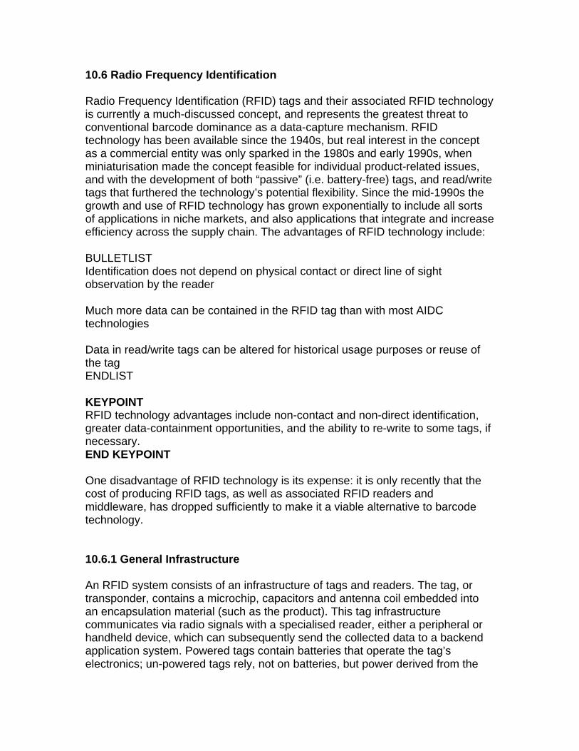
10.6 Radio Frequency Identification Radio Frequency Identification (RFID) tags and their associated RFID technology is currently a much-discussed concept, and represents the greatest threat to conventional barcode dominance as a data-capture mechanism. RFID technology has been available since the 1940s, but real interest in the concept as a commercial entity was only sparked in the 1980s and early 1990s, when miniaturisation made the concept feasible for individual product-related issues, and with the development of both “passive” (i.e. battery-free) tags, and read/write tags that furthered the technology’s potential flexibility. Since the mid-1990s the growth and use of RFID technology has grown exponentially to include all sorts of applications in niche markets, and also applications that integrate and increase efficiency across the supply chain. The advantages of RFID technology include: BULLETLIST Identification does not depend on physical contact or direct line of sight observation by the reader Much more data can be contained in the RFID tag than with most AIDC technologies Data in read/write tags can be altered for historical usage purposes or reuse of the tag ENDLIST KEYPOINT RFID technology advantages include non-contact and non-direct identification, greater data-containment opportunities, and the ability to re-write to some tags, if necessary. END KEYPOINT One disadvantage of RFID technology is its expense: it is only recently that the cost of producing RFID tags, as well as associated RFID readers and middleware, has dropped sufficiently to make it a viable alternative to barcode technology. 10.6.1 General Infrastructure An RFID system consists of an infrastructure of tags and readers. The tag, or transponder, contains a microchip, capacitors and antenna coil embedded into an encapsulation material (such as the product). This tag infrastructure communicates via radio signals with a specialised reader, either a peripheral or handheld device, which can subsequently send the collected data to a backend application system. Powered tags contain batteries that operate the tag’s electronics; un-powered tags rely, not on batteries, but power derived from the

RFID reader. Figure 10.3 depicts a typical RFID tag, with microchip and capacitor set-up at the centre, while the antenna-coil encircles it.
Figure 10.3: Passive and Active RFID tags respectively
KEYPOINT An RFID tag consists of an infrastructure that contains a microchip, capacitors, and antenna-coil. Depending on the tag type, it may or may not contain a battery. END KEYPOINT Each tag has a certain amount of internal memory where information about the object is stored, such as its unique ID number, or in some cases more detailed data including the date of manufacture, product composition, etc. The communication process between the reader and tag is managed and controlled by one of several protocols, such as ISO 15693, ISO 18000-3, ISO 18000-6, and Electronic Product Code (EPC) for different radio frequencies. In addition, different types of anti-collision algorithms are defined as part of these protocol standards, so that many tags presenting to one reader at the same time can be sorted and individually selected. Once the reader is on, it starts emitting a signal at a selected frequency. Any corresponding tag in the vicinity of the reader will detect the signal and use the energy from it to “wake-up” and supply operating power to its internal circuits. Once the tag has decoded the signal as valid, it replies with information to the reader thereby identifying the object. This information, called a notification, is then sent to RFID middleware. To deal with huge volumes of data (or notifications) from RFID tags, RFID middleware has been developed to act as a buffer between the RFID tag and the computing systems of the plant. RFID middleware has the ability to handle data operations, such as filtering, aggregation, and enrichment etc., as well as ensuring that data is processed into an appropriate format for application in the middleware. A reverse communication from the middleware to the RFID tag is also possible, which is called commands. Commands for RFID readers may be reading or writing commands which are emitted from the middleware based upon certain implemented rules. KEYPOINT

A RFID system consists of a number of RFID tags, RFID middleware, and the systems back-end computing systems. END KEYPOINT 10.6.2 RFID Tags There are two types of RFID tag: Active tags—that is, they contain and are independently powered by a battery; Passive tags (or unpowered tags)—which rely on power drawn from the reader to be activated. Active tags are larger, more expensive and, owing to the presence of the battery, have a limited life. Passive tags, on the other hand, are lighter, smaller, cheaper and have an unlimited life; however, they are inhibited by their relatively short read ranges, the requirement for high-powered readers, and by the fact that they can only be written to once (i.e. they are read-only). In contrast, active tags can use greater variability in readers and can be read at significantly longer distances, while they usually contain facilities to read and write a multiple number of times. KEYPOINT There are two types of RFID tag: active tags, which are battery-powered; and passive tags, which rely on power drawn from the reader to be activated. END KEYPOINT There also exist hybrids called semi-passive tags that use small batteries to operate the RFID chip’s circuitry, but rely on reader-power for communication. Table 10.6 summarizes some general aspects of RFID tag performance across a range of environments.
Table 10.6: RFID tag performance Frequencies Low Frequency High Frequency Ultra-High
Frequency Microwave
General Long antennas, more expensive. Less prone to interference from metals and liquids. Largely installed but will be overtaken by higher frequencies.
Shorter antennas, less expensive than low freq. tags. This frequency has the widest application scope. Best suited for applications that do not require long range reading of large amounts of tags.
Smaller, Cheaper. Higher frequency means these tags are potentially more powerful and have greater range. More susceptible to interference by metals and liquids. Different frequencies and power allocated by different countries.
Similar to ultra-high freq. but faster read rates. Much more susceptible to interference by metals and liquids. This frequency band is shared by other technologies, including bluetooth and many other short-range radio devices.

Standards Specifications
ISO/IEC 18000-2 ISO/IEC 18000-3, AutoID HFclass1, ISO 14443, ISO 15693
ISO/IEC 18000-6 AutoID class0, AutoID class 1
ISO/IEC 18000-4
Typical Read Range (typical values in metres)
< 0.5metres 1metre 4~5metres for unlicensed readers and 10metres for site license in the US; 2metres in Europe as power emissions increase to 2 watts.
1metre
Typical Applications
Access Control, Animal tagging
Smart cards, Access Control, Payment, Baggage control, Biometrics, Libraries, Transport
Pallet and box tagging, Baggage handling, Electronic toll collection
Electronic toll collection, Tracking the real time location of goods
Tag Read Rate Slowest Slow Medium Fast
KEYPOINT RFID tag performance depends upon the frequency under which it operates, as well as the RFID tag type. END KEYPOINT Current memory configurations on RFID tags tend to favour low-cost, memory-light, read-only tags that may only contain a unique serial number of the item, which, in this guise, operates in much the same way as a one-dimensional barcode. However, there are methods that can increase the memory capacity of an individual RFID tag, albeit with a consequent increase in its production cost. Vendors are regularly offering prospective customers ever-greater memory capacities, some as much as 128 kilobytes on high frequency, passive RFID applications. 10.6.3 RFID Memory There are three different types of RFID memory: NUMLIST ROM (read only memory) that stores security data, a unique device identifier and operating systems instructions, with electrically erasable programmable read only memory (EEPROM) being a specific type of ROM that has the ability to save tag data in its non-operative, power-saving state

RAM (random access memory) that stores data accrued during transponder interrogation and response WORM (write once / read many memory) that is similar in functionality to RAM. ENDLIST KEYPOINT There are three different types of RFID memory: read only memory; random access memory; and write once / read many memory. END KEYPOINT LEARNING ACTIVITY 10.2 Search the internet for videos, slides, articles and vendors for RFID technology used in industry. Write a short note of your findings. END LEARNING ACTIVITY 10.2 10.6.4 RFID Readers RFID readers communicate with the RFID tags via radio waves and pass information to the backend computer system in digital form. Readers can be configured in many formats including handheld devices, portals, or they may be conveyor-mounted. The user can change or customise the reader’s operations to suit a specific requirement by issuing commands through the RFID middleware. The purpose of an RFID reader is not to store data; rather it transfers data to and from the RFID tags, though short-term data storage is still required. The configuration information of a reader (e.g., the reader address, and configuration for filtering) is stored consistently during the entire operation of the RFID reader. Furthermore, in some cases, data acquired from the tags needs to be stored for short-term processing and forwarding to the middleware.

Figure 10.4: RFID tags and reader/sensor KEYPOINT RFID readers communicate with the RFID tags via radio waves and pass information to the backend computer system in digital form. END KEYPOINT When large numbers of RFID tags are presented to the RFID reader, data processing utilities are required to capture the high-volume data flows that occur. A reader can either process the field data from the tags, or the command data from the middleware (e.g., read/write commands). Pre-processing (e.g., filtering and aggregation) is used to relieve the middleware from processing too many notifications at any one time. Commands provided by the middleware (e.g., invoking a write operation on a tag) need to be stored for a short while and translated into internal RFID reader commands. 10.6.5 RFID Middleware RFID middleware acts as mediation between the RFID tag and the enterprise systems back-end. It is responsible for handling notifications, such as filtering, aggregation, enrichment, etc., according to specific rules implemented in the middleware.

KEYPOINT RFID middleware acts as mediation between the RFID tag and the enterprise systems back-end. END KEYPOINT Data processing in the middleware is similar to pre-processing in the RFID reader. Notifications that are irrelevant for the business process are filtered-out and faulty information is eliminated. The filtered notifications are then processed further to develop business events that are sent to enterprise computing back-end systems. This information can either be held locally in the middleware, or come from external devices, which are connected to the middleware (e.g., sensors, field databases, human user interfaces). Connections may also be developed to external information systems so that supplementation of the existing information by external sources can occur. For external information systems to operate successfully with RFID systems, automatic identification infrastructures are needed, such as the Object Naming Service (ONS) or the use of external WWAI network nodes (see Figure 10.5).
Figure 10.5: RFID Middleware KEYPOINT RFID middleware acts as an effective data-filter, and subsequently develops business events from the processed data that are sent to enterprise computing back-end systems. END KEYPOINT

10.7 Other AIDC technologies Other AIDC technologies that may occasionally be used in automation environments are summarised in Table 10.7.
Table 10.7: Other AIDC technologies Technology Description Magnetic Strips
These strips are attached to products or containers in warehouse and factory settings, and are used for product identification. The magnetic strip consists of a thin plastic film with small magnetic particles whose pole orientations are used to encode bits of data onto the film. The plastic film is usually mounted onto a plastic card (such as a credit card), or paper ticket to provide a robust infrastructure, and as means of automatic identification. Advantages include: the ability to hold large amounts of data, and the ability to alter data held, if necessary. Disadvantages, from a manufacturing point-of-view, include: the need to have the strip in contact with the scanning equipment for correct reading; the absence of shop-floor methods that can readily encode data to magnetic strips; and the expense of the technology.
Optical Character Recognition
Here specially designed alphanumeric characters that are machine readable by an optical reading device are deployed in factory and warehouse applications. Optical character recognition is a 2-D symbology, and scanning involves interpretation of both the vertical and horizontal features of each character during decoding. The use of hand-held operators, therefore, may require a certain level of skill on the part of human operators, to ensure that characters are read correctly; often this requires multiple scans of the code. The benefit of optical character recognition is that both machines and humans can read the same text. Disadvantages include: the need for near-contact scanning; lower scanning rates; and higher error rates compared to barcode scanning.
Machine vision
Used principally for automated inspection tasks, machine vision read 2-D matrix symbols, such as data matrix, or stacked barcodes. Applications of machine vision also include other types of automatic identification problems, and these applications may grow in number as the technology advances.
KEYPOINT Other AIDC technologies that may occasionally be used include: magnetic strips, optical character recognition, and machine vision technologies. END KEYPOINT

10.8 Case Study At its factory in Galway, Thermo King employees press a button to alert management whenever parts need to be replenished, thereby preventing work stoppages and part overstocks. Using AeroScout tags, the system is built onto the company's existing Wi-Fi system and was integrated by IMEC Technologies. This year, the firm is also in the process of expanding its usage of RFID at the Galway facility to include to asset tracking. The immediate challenge for Thermo King involved the development of what it calls its e-Kanban system (a signaling system to trigger an action such as inventory replenishment) that enables it to better manage the number of parts available at all assembly stations. The manual part-replenishment system employed prior to adopting RFID had several shortcomings. If workers discover they are running out of parts they must contact management, either by phone or by walking to the person in charge of ordering replenishment. If the company's on-floor inventory of parts runs out, work is stopped until additional components can be brought in from the warehouse. To avoid such problems in the past, companies typically store a high level of inventory at assembly stations. When space is tight companies need to establish a kanban system in which they only pull inventory [from the warehouse] when it is required. Thermo King first began discussing an automated solution with IMEC and AeroScout in early 2008 and the group conducted a proof-of-concept trial in April of that year, in which it tested the hardware to ensure proper read rates, then deployed the system throughout the entire factory in August. With the system, Ben-Assa says, the firm has installed approximately 100 AeroScout 2.4 GHz T2 tags, with a tag mounted next to each container of parts. When a container of parts runs low, an employee presses a button on its tag, which transmits its ID number to the Wi-Fi access points already installed throughout the facility to allow wireless laptop connectivity. The tag transmits not only its unique ID number, but also the assembly part serial number previously encoded when that tag was first installed. AeroScout Mobile View software links the ID number with the location at which the tag was installed, then transmits an e-mail alert to staff members in charge of replenishment, with the station number and the part number required, as well as the time at which the order was sent. 10.9 Unit Review BULLETLIST Automatic identification and data capture (AIDC) is the use of technology to provide direct data entry to a computer, or other micro-processor controlled

system, without resorting to manual methods of data-entry, such as via a keyboard. AIDC technologies consist of three principal technologies that are applied sequentially; these are data encoding, machine reading, and data decoding. AIDC can be categorised into optical, electromagnetic, magnetic, smart card, touch technique, and biometric technology types. Errors with AIDC technology are measured by two parameters: First Read Rate, and the Substitution Error Rate. Two types of barcode technology can be identified: linear barcode technology, and two-dimensional barcode technology. Barcodes in Code 39 consist of an arrangement of nine bars and spaces, which form a unique character for each arrangement; and a quiet-zone, consisting of empty space, which both precedes and succeeds the barcode in its presentation. The two basic types of 2-D barcodes are stacked barcodes, and matrix symbologies. Radio Frequency Identification technology represents the greatest threat to conventional barcode dominance as a data-capture mechanism. RFID technology advantages include non-contact and non-direct identification, greater data-containment opportunities, and the ability to re-write to some tags, if necessary. A RFID system consists of a number of RFID tags, RFID middleware, and the plant’s back-end computing systems. Communication can occur in both directions, both from the RFID tag backwards, and from the computing systems forwards. There are two types of RFID tag: active tags, which are battery-powered; and passive tags, which rely on power drawn from the reader to be activated. There are three different types of RFID memory: read only memory; random access memory; and write once / read many memory. RFID readers communicate with the RFID tags via radio waves and pass information to the backend computer system in digital form. RFID middleware acts as mediation between the RFID tag and the enterprise systems back-end.

Other AIDC technologies that may occasionally be used include: magnetic strips, optical character recognition, and machine vision technologies. ENDLIST 10.10 Self-Assessment Questions NUMLIST List the principal types of AIDC technologies, and the categories that these technologies can take. What are the types of barcode technology that can be identified? What is the major barcode standard that informs the use of barcodes made by most of contemporary industry? What are the two basic types of two-dimensional barcodes? What are the advantages that are associated with Radio Frequency Identification (RFID) technology? What are the major constituents of an RFID tag? How does RFID middleware act in the RFID system? Specify some other AIDC technologies. ENDLIST 10.11 Answers to Self-Assessment Questions NUMLIST AIDC technologies consist of three principal technologies that are applied sequentially; these are data encoding, machine reading, and data decoding. AIDC can be categorised into optical, electromagnetic, magnetic, smart card, touch technique, and biometric technology types. Two types of barcode technology can be identified: linear barcode technology, and two-dimensional barcode technology. Most major industries use a barcode standard that is based upon a subset of Code 39, known as AIM USD-2. The two basic types of two-dimensional barcodes are stacked barcodes, and matrix symbologies.

RFID technology advantages include non-contact and non-direct identification, greater data-containment opportunities, and the ability to re-write to some tags, if necessary. An RFID tag consists of an infrastructure that contains a microchip, capacitors, and antenna-coil. Depending on the tag type, it may or may not contain a battery. RFID middleware acts as mediation between the RFID tag and the enterprise systems back-end. It works as an effective data-filter, and subsequently develops business events from the processed data that are sent to enterprise computing back-end systems. Other AIDC technologies that may occasionally be used include: magnetic strips, optical character recognition, and machine vision technologies. END LIST