Unit 1 notes
60
Page | 1 V.R.S. College of Engineering & Technology, Arasur- 607107 (Accredited by NAAC and an ISO 9001:2008 Recertified Institution) Subject Name : COMPUTER AIDED DESIGN Subject code : ME6501 Year : III rd year Semester : V th semester ME6501-COMPUTER AIDED DESIGN Unit-I U
-
Upload
mahesh-pancity -
Category
Engineering
-
view
123 -
download
6
Transcript of Unit 1 notes

P a g e | 1
V.R.S. College of Engineering & Technology, Arasur-607107(Accredited by NAAC and an ISO 9001:2008 Recertified Institution)
Subject Name : COMPUTER AIDED DESIGN
Subject code : ME6501
Year : IIIrd year
Semester : Vth semester
ME6501-COMPUTER AIDED DESIGN Unit-I
U

P a g e | 2
ME6501 COMPUTER AIDED DESIGN L T P C 3 0 0 3
OBJECTIVES: To provide an overview of how computers are being used in mechanical component design
UNIT I FUNDAMENTALS OF COMPUTER GRAPHICS 9
Product cycle- Design process- sequential and concurrent engineering- Computer aided design –CAD system architecture- Computer graphics – co-ordinate systems- 2D and 3D transformations homogeneous coordinates - Line drawing -Clipping- viewing transformation
UNIT II GEOMETRIC MODELING 9
Representation of curves- Hermite curve- Bezier curve- B-spline curves-rational curves Techniques for surface modeling – surface patch- Coons and bicubic patches- Bezier and B spline surfaces. Solid modeling techniques- CSG and B-rep
UNIT III VISUAL REALISM 9
Hidden – Line-Surface-Solid removal algorithms – shading – colouring – computer animation.
UNIT IV ASSEMBLY OF PARTS 9
Assembly modelling – interferences of positions and orientation – tolerance analysis massproperty calculations – mechanism simulation and interference checking.
UNIT V CAD STANDARDS 9
Standards for computer graphics- Graphical Kernel System (GKS) - standards for exchange images-Open Graphics Library (OpenGL) - Data exchange standards - IGES, STEP, CALSetc. communication standards.
TOTAL : 45 PERIODS
OUTCOMES: Upon completion of this course, the students can able to use computer and CAD software's for modeling of mechanical components
TEXT BOOKS:
1. Ibrahim Zeid “Mastering CAD CAM” Tata McGraw-Hill Publishing Co.2007
REFERENCES:
ME6501-COMPUTER AIDED DESIGN Unit-I
U

P a g e | 3
1. Chris McMahon and Jimmie Browne “CAD/CAM Principles", "Practice and Manufacturing management “ Second Edition, Pearson Education, 1999.
2. William M Neumann and Robert F.Sproul “Principles of Computer Graphics”, McGraw Hill Book Co. Singapore, 1989.
3. Donald Hearn and M. Pauline Baker “Computer Graphics”’. Prentice Hall, Inc, 1992.
4. Foley, Wan Dam, Feiner and Hughes - "Computer graphics principles & practice" Pearson Education - 2003.
UNIT 1
FUNDAMENTALS OF COMPUTER GRAPHICS
CLASS NOTES
1. Explain Product life cycle with design process. (Or) Briefly explain the conventional process of the product cycle in the conventional manufacturing environment. (Nov 08)
Product Life Cycle:
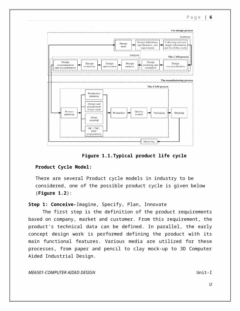
Figure 1.1.shows the life cycle of a typical product. The product begins with a need which is identified based on customers’ and markets’ demands. The product goes through two main processes from the idea conceptualization to the finished product: The design process and the manufacturing process.
Design process: The product goes through two main processes from inception to a finished product: the design process and the manufacturing process. Synthesis and analysis are the two main subprocesses of the design process.
Synthesis: The philosophy, functionality, and uniqueness of the product arc all determined during synthesis. During synthesis, a design takes the form of sketches and layout drawings that show the relationship among the various product parts. These sketches and drawings can be created using a CAD/CAM system or simply hand-drawn on paper. They are used during brainstorming discussions among various design teams and for presentation purposes.
Analysis: The analysis subprocess begins with an attempt to put the conceptual design into the context of engineering sciences to evaluate the performance of the expected product. This
ME6501-COMPUTER AIDED DESIGN Unit-I
U

P a g e | 4
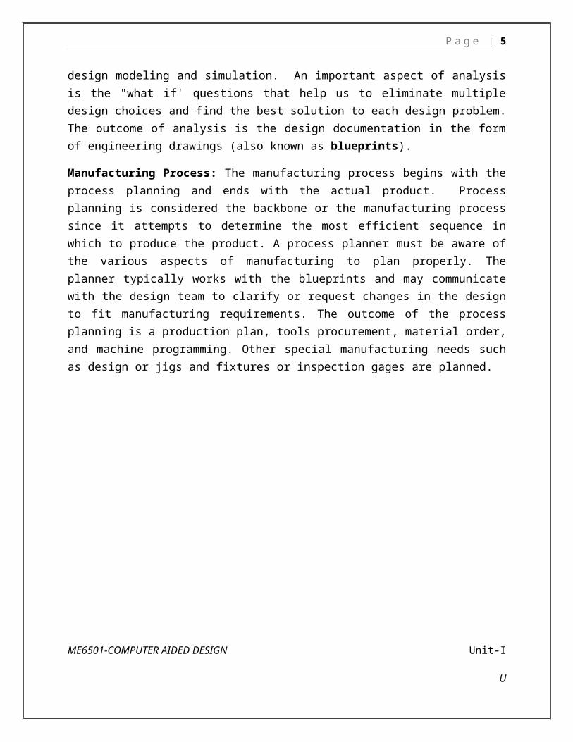
requires design modeling and simulation. An important aspect of analysis is the "what if' questions that help us to eliminate multiple design choices and find the best solution to each design problem. The outcome of analysis is the design documentation in the form of engineering drawings (also known as blueprints).
Manufacturing Process: The manufacturing process begins with the process planning and ends with the actual product. Process planning is considered the backbone or the manufacturing process since it attempts to determine the most efficient sequence in which to produce the product. A process planner must be aware of the various aspects of manufacturing to plan properly. The planner typically works with the blueprints and may communicate with the design team to clarify or request changes in the design to fit manufacturing requirements. The outcome of the process planning is a production plan, tools procurement, material order, and machine programming. Other special manufacturing needs such as design or jigs and fixtures or inspection gages are planned.
Figure 1.1.Typical product life cycle
Product Cycle Model:
There are several Product cycle models in industry to be considered, one of the possible product cycle is given below (Figure 1.2):
ME6501-COMPUTER AIDED DESIGN Unit-I
U
P a g e | 5
Step 1: Conceive-Imagine, Specify, Plan, Innovate The first step is the definition of the product requirements based on company, market and
customer. From this requirement, the product's technical data can be defined. In parallel, the early concept design work is performed defining the product with its main functional features. Various media are utilized for these processes, from paper and pencil to clay mock-up to 3D Computer Aided Industrial Design. Step 2: Design-Describe, Define, Develop, Test, Analyze and Validate
This is where the completed design and development of the product begins, succeeding to prototype testing, through pilot release to final product. It can also involve redesign and ramp for Improvement to existing products as well as planned obsolescence. The main tool used for design and development is CAD. This can be simple 2D drawing / drafting or 3D parametric feature based solid/surface modeling. This step covers many engineering disciplines including: electronic, electrical, mechanical, and civil. Besides the actual making of geometry there is the analysis of the components and assemblies. Optimization, Validation and Simulation activities are carried out using Computer Aided Engineering (CAE) software. These are used to perform various tasks such as: Computational Fluid Dynamics (CFD); Finite Element Analysis (FEA); and Mechanical Event Simulation (MES). Computer Aided Quality (CAQ) is used for activities such as Dimensional tolerance analysis.
Figure 1.2.Product Cycle ModelME6501-COMPUTER AIDED DESIGN Unit-I
U
P a g e | 6
Step 3: Realize-Manufacture, Make, Build, Procure, Produce, Sell and Deliver Once the design of the components is complete the method of manufacturing is finalized.
This includes CAD operations such as generation of CNC Machining instructions for the product’s component as well as tools to manufacture those components, using integrated Computer Aided Manufacturing (CAM) software. It includes Production Planning tools for carrying out plant and factory layout and production simulation. Once details components are manufactured their geometrical form and dimensions can be verified against the original data with the use of Computer Aided Inspection Equipment (CAIE). Parallel to the engineering tasks, sales and marketing work take place. This could consist of transferring engineering data to a web based sales configuration. Step 4: Service-Use, Operate, Maintain, Support, Sustain, Phase-out, Retire, Recycle and Disposal
The final step of the lifecycle includes managing of information related to service for repair and maintenance, as well as recycling and waste management information. This involves using tools like Maintenance, Repair and Operations Management software.
2. Briefly explain about design process.
Design Process The design process includes series of steps that engineers apply in making functional
products and processes. The parts of the process often need to be repeated many times before production of a product can start. The parts that get iterated and the number of such design cycles in any given project can be highly changeable. One method of the engineering design process focuses on the following common aspects: 1. Research
A considerable amount of time is used on research, or finding information. Consideration should be given to the available applicable literature, issues and successes linked with available solutions, and need of marketplaces. The basis of information should be significant, including existing results. Reverse engineering can be a successful technique if other solutions are available in the market. Added sources of information include the trade journals, available government documents, local libraries, vendor catalogs and personal organizations. 2. Feasibility assessment
The feasibility study is an analysis and assessment of the possible of a proposed design which is based on detail investigation and research to maintain the process of decision creation. The feasibility assessment helps to focus the scope of the project to spot the best situation. The purpose of a feasibility assessment is to verify whether the project can continue into the design phase.
ME6501-COMPUTER AIDED DESIGN Unit-I
U

P a g e | 7
Fig.2.1. Design Process3. Conceptualization
A Concept Study is the stage of project planning that includes developing ideas and taking into account the all features of executing those ideas. This stage of a project is done to reduce the likelihood of assess risks, error and evaluate the potential success of the planned project. 4. Establishing the design requirements
Establishing design requirements is one of the most essential elements in the design practice, and this task is usually performed at the same time as the feasibility analysis. The design requirements control the design of the project all over the engineering design process. A few design requirements comprise maintainability, hardware and software parameters, availability, and testability. 5. Preliminary design
The preliminary design fills the gap between the design concept and the detailed design phase. During this task, the system configuration is defined, and schematics, diagrams, and layouts of the project will offer early project configuration. In detailed design and optimization, the parameters of the part being produced will change, but the preliminary design focuses on creating the common framework to construct the project. 6. Detailed design
The next phase of preliminary design is the Detailed Design which may include of procurement also. This phase builds on the already developed preliminary design, aiming to further develop each phase of the project by total description through drawings, modeling as well as specifications. The advancement CAD programs have made the detailed design phase more competent. This is because a CAD program can offer optimization, where it can shrink volume without
ME6501-COMPUTER AIDED DESIGN Unit-I
U

P a g e | 8
compromising the part's quality. It can also calculate displacement and stress using the FEM to find stresses throughout the part. It is the responsibility of designer to find whether these stresses and displacements are acceptable, so the part is safe. 7. Production planning and tool design
The production planning and tool design is more than planning how to mass-produce the project and which tools should be used in the manufacturing of the component. Tasks to complete in this stage include material selection, identification of the production processes, finalization of the sequence of operations, and selection of jigs, fixtures, and tooling. This stage also includes testing a working prototype to confirm the created part meets qualification standards. With the finishing of qualification testing and prototype testing, the design process is completed.
(Or)
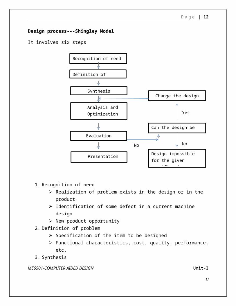
Design process---Shingley Model
It involves six steps
1. Recognition of need Realization of problem exists in the design or in the product Identification of some defect in a current machine design New product opportunity
ME6501-COMPUTER AIDED DESIGN Unit-I
U
Recognition of need
Definition of problem
Synthesis
Analysis and Optimization
Evaluation
Presentation
Change the design
Can the design be improved
Design impossible for the given specifications
Yes
NoNo

P a g e | 9
2. Definition of problem Specification of the item to be designed Functional characteristics, cost, quality, performance, etc.
3. SynthesisPreliminary ideas are developed through research of similar product or designs in use.
4. Analysis and Optimization Suitability for the specified design constraints If not suitable or design fails to satisfy the constraints Then redesign or modified iteration continues until the proposed design meet the
specifications (or) until feasibility is achieved. Then components, sub-assemblies or sub-systems are then synthesized into the
final overall system in a similar iterative manner.5. Evaluation
Prototyping Testing Quality Reliability testing
6. PresentationDocumentation of the design through drawings, material specifications, assembly lists, etc.
Pahl and Beitz Model: 1. Clarification of the task: Collection of information, constraints on the design.2. Conceptual design: establishment of the functions to be included in the design, 3. Embodiment design: problems are resolved and weak aspects are eliminated4. Detail design: The dimensions, tolerance, materials and form of individual
components of the design are specified in design for subsequent manufacturing.
3. Write briefly on Sequential and Concurrent Engineering.
Sequential Engineering:
Sequential engineering is the term used to explain the method of production in a linear system. The various steps are done one after another, with all attention and resources focused on that single task.
Sequential engineering is a system by which a group within an organization works sequentially to create new products and services.
The sequential engineering is a linear product design process during which all stages of manufacturing operate in serial. Both process and product design run in serial and take place in the different time.
ME6501-COMPUTER AIDED DESIGN Unit-I
U

P a g e | 10
Process and Product are not matched to attain optimal matching. Decision making done by only group of experts.
Sequential Engineering
Concurrent Engineering:
In concurrent engineering, various tasks are handled at the same time, and not essentially in the standard order. This means that info found out later in the course can be added to earlier parts, improving them, and also saving time.
Concurrent engineering
Concurrent engineering is a method by which several groups within an organization work simultaneously to create new products and services.
The concurrent engineering is a non-linear product design process during which all stages of manufacturing operate at the same time. Both product and process design run in parallel and take place in the same time.
ME6501-COMPUTER AIDED DESIGN Unit-I
U

P a g e | 11
Process and Product are coordinated to attain optimal matching of requirements for effective quality and delivery.
Decision making involves full team involvement.
4. Write briefly on Computer Aided Design.
CAD is the intersection of Computer Graphics, Geometric modeling and Design tools (Fig.4.1.). The concepts of computer graphics and geometric modeling and must be used innovatively to serve the design process. CAD is the function of computer systems to support in the creation, modification, analysis, or optimization of a design.
Fig.4.1.CAD
CAD software for design uses either vector-based graphics to explain the objects of traditional drafting, or may also develop raster graphics showing the overall look of designed objects. During the manual drafting of engineering drawings, the output of CAD must convey information, like dimensions, materials, processes, and tolerances.
CAD is a significant industrial art used in many purposes, including industrial and architectural design, shipbuilding, automotive, and aerospace industries, and many more. CAD is also extensively used to create computer animation for special effects in movies, and technical manuals, frequently called as Digital Content Creation.
CAD software packages provide the designer with a multi window environment with animation which is regularly used in Digital Content Creation. The animations using wire frame modeling helps the designer to see into the interior of object and to observe the behaviors of the inner components of the assembly during the motion.
CAD Tools The CAD tools are mainly using for graphics applications and modeling. Aids such a color, grids,
geometric modifiers and group facilitate structural geometric models. Visualization is achieved through shaded components and animation which focus design conceptualization, communication and interference detection. FEM packages provide optimization in shape and structure. Adding tolerances,
ME6501-COMPUTER AIDED DESIGN Unit-I
U
P a g e | 12
tolerance analysis and investigating the effect of manufacturing on the design can perform by utilizing CAD tools.
CAD Tools Design Process
Geometric modeling, Graphics aids, visualization and manipulation
Conceptualization
Geometric modeling, Graphics aids, visualization and manipulation, animation, assemblies
Modeling and Simulation
Analysis packages, customized programs Design AnalysisStructural optimization Design Optimization
Dimensioning, tolerance, bill of materials Design evaluation
Drafting and detailing , Shaded imagesCommunication and Documentation
Uses of CAD
CAD is one of the tools used by designers and engineers and is used in different ways depending on the profession of the customer and the type of software.
CAD is one of the Digital Product Development activities within the Product LifecycleManagement practices with other tools, which are either integrated modules or individual, such as:
Computer Aided engineering (CAE) and Finite Element Analysis (FEA) Computer Aided Manufacturing (CAM) Realistic Rendering and Simulation. Product Data Management (PDM).CAD is also used for the development of photo simulations that are frequently necessary in the
preparation of Environmental Impact Reports, in which proposed CAD buildings are superimposed into photographs of existing situation to represent what that conditions will be like, where the proposed services are allowed to be built.
Parameters and constraints can be used to get the size, shape, and other properties of the modeling elements. The features of the CAD system can be used for the several tools for measurement; such as yield strength, tensile strength and electrical or electro-magnetic properties.
CAD System ArchitectureComputer architecture is a pattern describing how a group of software and hardware technology
standards relate to form a computer system. In general, computer architecture refers to how a computer is designed and what technologies it is compatible with. Computer architecture is likened to the art of shaping the needs of the technology, and developing a logical design and standards based on needs.
5. Write short notes on Scope and applications of CAD/CAM
Scope of CAD/CAM
ME6501-COMPUTER AIDED DESIGN Unit-I
U

P a g e | 13
At the core of the CAD and CAM processes is a geometric model of the product under design. Activities of the CAD process include mass properties, finite element analysis, dimensioning. tolerancing, assembly modeling, generating shaded images, and documentation and drafting. Activities of the CAM process include CAPP (Computer Aided Process Planning), NC (numerical control) programming, design of injection mold, CMM (coordinate measuring machine) verification, inspection, assembly via robots, and packaging.
The CAD process and its tools utilize three disciplines: geometric modeling, computer graphics, and design. The CAM process utilizes the disciplines of CAD itself, manufacturing, and automation.
CAD/CAM Applications
There are considerable numbers of applications for the various existing CAD/CAM systems. For example, there are mechanical, electrical, and architectural CAD and CAM products. An inspection of these various systems reveals that they have a generic structure and common modules. Awareness of such structure and modules enables users to better understand system functions for both evaluation and training purposes.
The major available modules are
The geometric engine (module) is the heart of a CAD/CAM system. It provides users with functions to perform geometric modeling and construction. Editing and manipulation of existing geometry, drafting and documentation. The typical modeling operations that users can engage in arc model creation, cleanup, documentation, and printing/plotting. Shaded images can be generated as part of model documentation.
ME6501-COMPUTER AIDED DESIGN Unit-I
U

P a g e | 14
Fig.5.1 CAD and CAM disciplines
The applications module varies from one software system to another. However, there are common applications shared by most CAD/CAM systems. Mechanical applications include mass property calculations, assembly analysis, tolerance analysis and synthesis, sheet metal design, finite element modeling and analysis, mechanisms analysis, animation techniques, and simulation and analysis of plastic injection molding. Manufacturing applications include CAPP, NC, CIM, robot simulation, and group technology.
The programming module allows users to customize systems by programming them to fit certain design and manufacturing tasks. A CAD/CAM system requires advanced knowledge of the system architecture, its database format, and a high-level programming language such as C, C++, Java, Scheme, or others.
The communications module is crucial if integration is to be achieved between the CAD/CAM system, other computer systems, and manufacturing facilities. It is common to network the system to transfer the CAD database of a model for analysis purposes or to transfer its CAM database to the shop floor for production. This module also serves the purpose of translating databases between CAD/CAM systems using graphics standards such as IGES and STEP.
The collaborative module is emerging as an outcome of the widespread of the World Wide Web and the Internet. This module supports collaborative design. Various design teams in different geographical locations can work concurrently on the same part, assembly, or drawing file in real time over the Web. One team can make changes that other teams can view and accept or reject.
The various CAD/CAM systems support engineering design, analysis, and manufacturing applications. They all have a flexible pricing structure that allows customers to add on applications as needed.
6. Write short notes on: CAD, CAD process, components of CAD system, and advantages of CAD systems.
Computer-Aided Design (CAD)
CAD can be defined as the use of computer systems to perform certain functions in the design process. Use of computer systems to assist in the creation, modification, analysis, and optimization of a design
In general, a Computer Aided Design (CAD) package has three components: a) Design, b) Analysis, and c) Visualization. A brief description of these components follows.
ME6501-COMPUTER AIDED DESIGN Unit-I
U

P a g e | 15
a) Design: Design refers to geometric modeling, i.e., 2-D and 3-D modeling, including, drafting, part creation, creation of drawings with various views of the part, assemblies of the parts, etc.
b) Analysis: Analysis refers to finite element analysis, optimization, and other number crunching engineering analyses. In general, a geometric model is first created and then the model is analyzed for loads, stresses, moment of inertia, and volume, etc.
c) Visualization: Visualization refers to computer graphics, which includes: rendering a model, creation of pie charts, contour plots, shading a model, sizing, animation, etc.
Each of these three areas has been extensively developed in the last 30 years Several books are written on each of these subjects and courses are available through the academic institutions and the industry.
Typical tools:
– Tolerance analysis
– Mass property calculations
– Finite-element modeling and visualization
Defines the geometry of the design
Computer-Aided Design Process
Two types of activities: synthesis and analysis
Synthesis is largely qualitative and hard to capture on computer.
Analysis can be greatly enhanced with computers.
Once analysis is complete, design evaluation- rapid prototyping are done.
ME6501-COMPUTER AIDED DESIGN Unit-I
U

P a g e | 16
Fig 6.1.Components of CAD/CAM/CAE Systems
CAD HardwareThere are basically two types of devices that constitute CAD hardware: a) Input devices, and b) Output devices.
Input DevicesThese are the devices that we use for communicating with computer, and providing our
input in the form of text and graphics. The text input is mainly provided through keyboard. For graphic input, there are several devices available and used according to the work environment. A brief description of these devices is given here.Mouse: This is a potentiometric device, which contains several variable resistors that send signals to the computer. The functions of a mouse include locating a point on the screen, sketching, dragging an object, entering values, accepting a software command, etc. Joystick and trackballs are analogous to a mouse device, and operate on the same principle.Digitizers: Digitizers are used to trace a sketch or other 2-D entities by moving a cursor over a flat surface (which contains the sketch). The position of the cursor provides a feedback to the computer connected with the device. There are electrical wires embedded in orthogonal directions that receive and pass signals between the device and the computer. The device is basically a free moving pen shaped stylus, connected to a tablet.Light Pens: Lockheed’s CADAM software utilized this device to carry out the graphic input. A light pen looks like a pen and contains a photocell, which emits an electronic signal. When the pen is pointed at the monitor screen, it senses light, which is converted to a signal. The signal is sent to the computer, for determination of the exact location of the pen on the monitor screen.Touch Sensitive Screens: This device is embedded in the monitor screens, usually, in the form of an overlay. The screen senses the physical contact of the user. The new generation of the Laptop computers is a good example of this device.
ME6501-COMPUTER AIDED DESIGN Unit-I
U

P a g e | 17
Other Graphic Input Devices: In addition to the devices described above, some CAD software will accept input via Image Scanners, which can copy a drawing or schematic with a camera and light beam assembly and convert it into a pictorial database.
The devices just described are, in general, independent of the CAD package being used. All commercial CAD software packages contain the device drivers for the most commonly used input devices. The device drivers facilitate a smooth interaction between our input, the software, and the computer. An input device is evaluated on the basis of the following factors:
• Resolution
• Accuracy
• Repeatability
• Linearity
Output Devices
After creating a CAD model, we often need a hard copy, using an output device. Plotters and printers are used for this purpose.
A plotter is often used to produce large size drawings and assemblies, whereas, a laser jet printer is adequate to provide a 3-D view of a model. Most CAD software require a plotter for producing a shaded or a rendered view.
CAD Software
CAD software is written in FORTRAN and C languages. FORTRAN provides the number crunching, whereas, C language provides the visual images.
The modern CAD software utilizes the open architecture system, i.e., software vendors do not design and manufacture their own hardware. Third party software can be used to augment the basic CAD package.
Most popular CAD package will facilitate integration of the Finite Element Analysis and other CAD software from more than one vendor. For example, IDEAS preprocessor can work with almost all the FEA packages for pre and post analyses.
Networking is an important consideration in applications of CAD software. A model created by one engineer must be readily accessible to others in an organization, which is linked by a LAN or other means. The designer, analyst, management, marketing, vendor, and others generally share a model. This is the concurrent engineering in action, mentioned earlier.
CAD Platform
In general, we can run CAD software on three different CAD platforms: Mainframe, Workstation, and PC.
When the CAD programs first became available, they could only be run on a mainframe computer. However, as the PCs have become faster and cheaper, almost all the CAD vendors have introduced a version of their CAD software that will effectively run on a
ME6501-COMPUTER AIDED DESIGN Unit-I
U

P a g e | 18
Pentium or higher computer. Currently, the most popular platforms are PCs and Workstations.
Popularity of Workstations stems from their ability to network easily with other computers, and also, due to their large memory storage capability. However, PC platform is still the most preferred medium for most engineers.
Increasing popularity of the PC platform can be attributed to several factors, including, total user control, the speed, capability of storing large memory, ease of hardware upgrading and maintenance, and the overall reasonable cost.
CAD PLATFORMS
MAINFRAME WORKSTATIONS PCs
MAINFRAME WORKSTATIONS PCsLarge Data storage Medium size data storage Limited data storageNetworked Networked Can be networked
Expensive Relatively inexpensive Inexpensive
Need interface language Runs on Unix Run on MS-Windows
No user control No user control User controlled
Good for Large corporationsGood for small companies Good for all users
Advantages of CAD/CAM systems
Greater flexibility, Reduced lead times, Reduced inventories, Increased Productivity, Improved customer service, Improved quality, Improved communications with suppliers, Better product design, Greater manufacturing control, Supported integration, Reduced costs, Increased utilization, Reduction of machine tools, Less floor space
CAD/CAM Applications – Ref Q.No:5
7. Write short notes on: Concurrent Engineering, Characteristics of Concurrent Engineering with example.
Characteristics of Concurrent Engineering
ME6501-COMPUTER AIDED DESIGN Unit-I
U

P a g e | 19
In concurrent engineering functional divisions like design, manufacturing and quality are integrated in a compatible environment. The integration comes in the form of instant delivery of information about business processes across the enterprise. Cross functional units co-operate concurrently rather than sequentially. The real-time sharing of information enables teams to make design modifications early in a product development cycle, thus reducing unwanted rework and engineering changes that increase cost of operations, reduce product quality and delay the time-to-market.
The concurrent engineering approach can be characterized by the following factors:
• Integration of product and process development and logistics support• Closer attention to the needs of customers• Adoption of new technologies• Continuous review of design and development process• Rapid and automated information exchange• Cross functional teams• Rapid prototyping
Example of Concurrent EngineeringThe story of the development of Neon Car in USA is a typical example of success of
concurrent engineering. The planning of the car started in August 1990. For each major item product teams were made. Supporting teams were organized for such
activities like dimension control, materials etc. The composition of a typical team included representatives from engineering, stamping, manufacturing processes, assembly, design, purchase, finance, product planning, materials handling and vendor development. Even suppliers were part of the product development team. Each team took approximately one year to complete a task. Subsequently process teams were organized to manufacture the product. Four months before the launch the process teams were converted into launch teams to successfully introduce the product in the market.
Another example for successful implementation of concurrent engineering is the development of Scooty moped and other products by TVS Motors Ltd. in India. Before taking up the design cross functional teams were formed to design and engineer the product. This reduced not only the product development time but also helped the manufacturer to introduce the quality product in the market.
8. Briefly explain the Coordinate Systems and its types
Coordinate Systems
Three types of coordinate systems are needed in order to input, store, and display model geometry and graphics. These are Model Coordinate System (MCS), Working Coordinate System (WCS) and Screen Coordinate System (SCS), respectively. Other names for MCS are
ME6501-COMPUTER AIDED DESIGN Unit-I
U

P a g e | 20
database, master, or world coordinate system. Another name for SCS is device coordinate system.Model Coordinate System
The model coordinate system is defined as the reference space of the model with respect to which all the model geometrical data is stored.
It is a Cartesian system which forms the default coordinate system used by a particular software program. The X, Y, and Z axes of the MCS can be displayed on the computer screen. The origin of the MCS can be arbitrarily chosen by the user while its orientation is established by the software.
The three default sketch planes of a CAD/CAM system define the three planes of the MCS, and their intersection point is the MCS origin. When a CAD designer begins sketching, the origin becomes a corner point of the profile being sketched. The sketch plane defines the orientation of the profile in the model 3D space.
In order for the user to communicate properly and effectively with a model database, the relationship between the MCS orthogonal (sketch) planes and the model views must be understood by the user. Typically, the software chooses one of two possible orientations of the MCS in space.
Fig 8.1.Possible orientation
As shown in Figure8.1a, the XY plane is the horizontal plane and defines the model top view. The front and right side views are consequently defined by the XZ and YZ planes, respectively. Figure 8.1b shows the other possible orientation of the MCS where the XY plane is vertical and defines the model front view. As a result, the XZ and the YZ planes define the top and the right side views, respectively.
Existing CAD/CAM software uses the MCS as the default WCS. In both orientations, the XY plane is the default construction (sketch) plane. If the user utilizes such a plane, the first face of a model to be constructed becomes the top or front view, depending on which MCS is used.
ME6501-COMPUTER AIDED DESIGN Unit-I
U

P a g e | 21
The MCS is the only coordinate system that the software recognizes when storing or retrieving graphical information in or from a model database. Many existing software packages allow the user to input coordinate information in cartesian (x, y. z) and cylindrical (r, θ, z) coordinates. This input information is transformed to (x, y. z) coordinates relative to the MCS before being stored in the database.
Obtaining views is a form of retrieving graphical information relative to the MCS. If the MCS orientation does not match the desired orientation of the object being modeled, users become puzzled and confused.
Another form of retrieving information is entity verification. Coordinates of points defining the entity are given relative to MCS by default. However, existing software allows users to obtain the coordinates relative to another system (WCS) by using the proper commands or modifiers
Working Coordinate System
It is often convenient in the development of geometric models and the input of geometric data to refer to an auxiliary coordinate system instead of the MCS. This is usually useful when a desired plane (face) of construction is not easily defined as one of the MCS orthogonal planes, as in the case of inclined faces of a model. The user can define a Cartesian coordinate system whose XY plane is coincident with the desired plane of construction. That system is the Working Coordinate System, WCS. It is a convenient user-defined system that facilitates geometric construction.
It can be established at any position and orientation in space that the user desires. While the user can input data in reference to the WCS, the CAD software performs the necessary transformations to the MCS before storing the data.
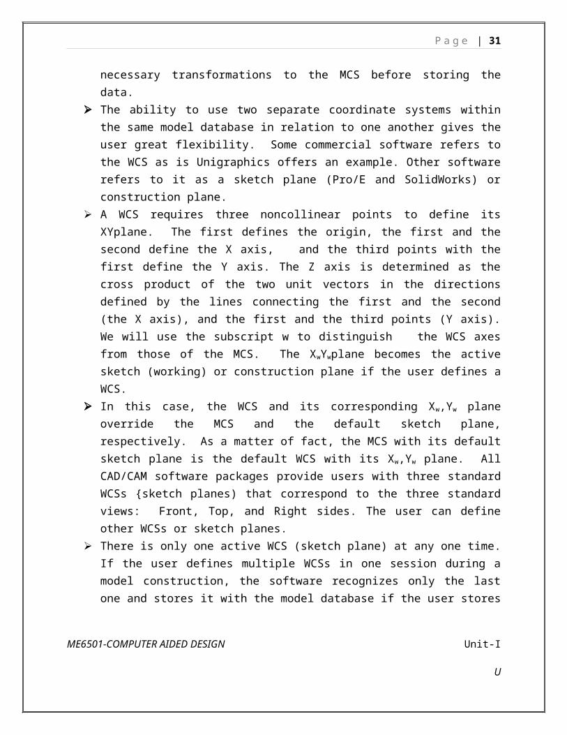
The ability to use two separate coordinate systems within the same model database in relation to one another gives the user great flexibility. Some commercial software refers to the WCS as is Unigraphics offers an example. Other software refers to it as a sketch plane (Pro/E and SolidWorks) or construction plane.
A WCS requires three noncollinear points to define its XYplane. The first defines the origin, the first and the second define the X axis, and the third points with the first define the Y axis. The Z axis is determined as the cross product of the two unit vectors in the directions defined by the lines connecting the first and the second (the X axis), and the first and the third points (Y axis). We will use the subscript w to distinguish the WCS axes from those of the MCS. The XwYwplane becomes the active sketch (working) or construction plane if the user defines a WCS.
In this case, the WCS and its corresponding Xw,Yw plane override the MCS and the default sketch plane, respectively. As a matter of fact, the MCS with its default sketch plane is the default WCS with its Xw,Yw plane. All CAD/CAM software packages provide users with three standard WCSs {sketch planes) that correspond to the three
ME6501-COMPUTER AIDED DESIGN Unit-I
U

P a g e | 22
standard views: Front, Top, and Right sides. The user can define other WCSs or sketch planes.
There is only one active WCS (sketch plane) at any one time. If the user defines multiple WCSs in one session during a model construction, the software recognizes only the last one and stores it with the model database if the user stores the model. The model tree displayed by the CAD software shows the last selected (activated) sketch plane.
Once a WCS is defined, user coordinate inputs are interpreted by the software in reference to this system. The software calculates the corresponding homogeneous transformation matrix between the WCS and the MCS to convert these input values into coordinates relative to the MCS before storing them in the database. The transformation equation can be written as:
Pm = T Pw
where Pm is the position vector of a point relative to the MCS and Pw is the vector of the point relative to the active WCS. Each vector is given by:
P = [x y z 1] T
The matrix [T] is the homogeneous transformation matrix. It is a 4 x 4 matrix and is given by:
Where [ R ]wm is the rotation matrix that definesthe orientation of the WCS relative to the MCS and
[ P ]w orgm is the position vector that describes the origin of the WCS relative to the MCS. The
columns of[ R ]wm: give the direction cosines of the unit vectors in the Xw, Yw and Zw directions
relative to the MCS as shown in Figure .These direction cosines are the components of the unit vectors along the axes of the MCS.
If the WCS axes are along the MCS axes, then the direction cosines become 1, -1, or 0, and if X w
and Yw are aligned along the Z and X axes of the MCS, respectively, the transformation between the WCS and MCS is given by:
Observe that one of the matrix in eqn. is inverse of the other; their manipulation produces the identity Matrix, I.
ME6501-COMPUTER AIDED DESIGN Unit-I
U

P a g e | 23
Screen Coordinate System
In contrast to the MCS and WCS, the screen coordinate system (SCS) is defined as a 2D device-dependent coordinate system whose origin is usually located at the lower left comer of the graphics display, as shown in Figure.
The physical dimensions of a device screen (aspect ratio) and the type of device (raster) determine the range of the SCS. The SCS is mostly used in view-related clicks such as definitions of view origin and window or clicking a view to select it for graphics operations.
A 1024 x 1024 display has an SCS with a range of (0, 0) to (1024, 1024). The center of the screen has coordinates of (512,512). This SCS is used by the CAD/CAM software to display relevant graphics by converting directly from MCS coordinates to SCS (physical device) coordinates. A normalized SCS can also be utilized. The range of the SCS can be chosen from (0, 0) to (I, 1).
Such representation can be translated by device-dependent codes to the appropriate physical device coordinates. The third method of defining an SCS is by using the drawing size that the user chooses.
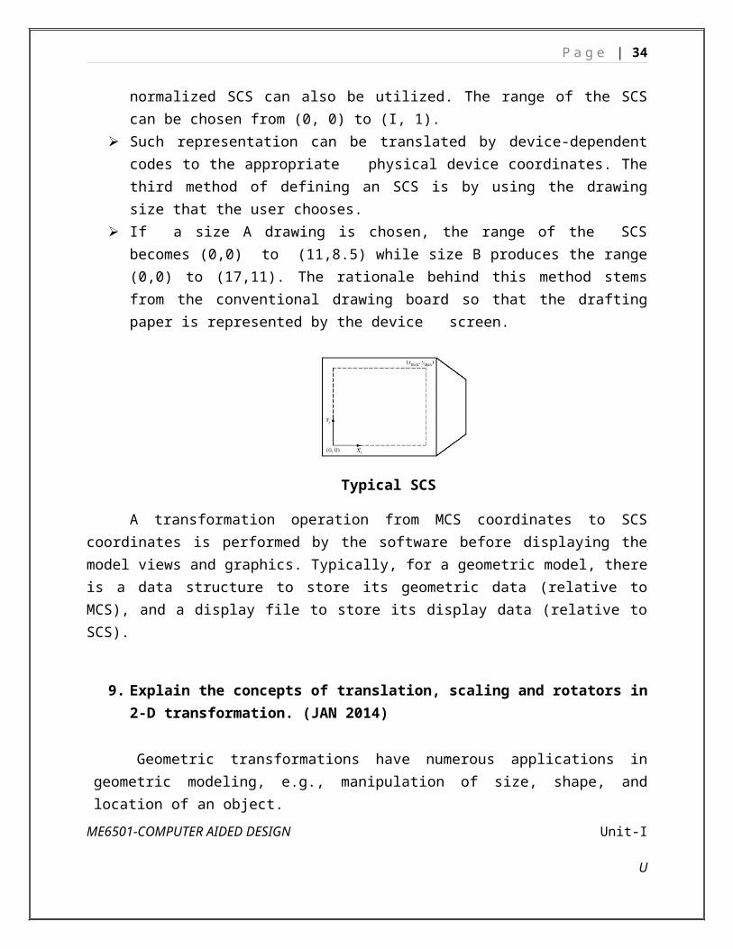
If a size A drawing is chosen, the range of the SCS becomes (0,0) to (11,8.5) while size B produces the range (0,0) to (17,11). The rationale behind this method stems from the conventional drawing board so that the drafting paper is represented by the device screen.
ME6501-COMPUTER AIDED DESIGN Unit-I
U

P a g e | 24
Typical SCS
A transformation operation from MCS coordinates to SCS coordinates is performed by the software before displaying the model views and graphics. Typically, for a geometric model, there is a data structure to store its geometric data (relative to MCS), and a display file to store its display data (relative to SCS).
9. Explain the concepts of translation, scaling and rotators in 2-D transformation. (JAN 2014)
Geometric transformations have numerous applications in geometric modeling, e.g., manipulation of size, shape, and location of an object.
In CAD, transformation is also used to generate surfaces and solids by sweeping curves and surfaces, respectively. The term ‘sweeping’ refers to parametric transformations, which are utilized to generate surfaces and solids. When we sweep a curve, it is transformed through several positions along or around an axis, generating a surface.
The appearance of the generated surface depends on the number of instances of the transformation. There are two types of transformations:
Modeling Transformation:This transformation alters the coordinate values of the object. Basic operations are
scaling, translation, rotation and, combination of one or more of these basic transformations. Examples of these transformations can be easily found in any commercial CAD software. For instance, AutoCAD uses SCALE, MOVE, and ROTATE commands for scaling, translation, and rotation transformations, respectively.Visual Transformation:
In this transformation there is no change in either the geometry or the coordinates of the object. A copy of the object is placed at the desired sight, without changing the coordinate values of the object. In AutoCAD, the ZOOM and PAN commands are good examples of visual transformation.
Two-Dimensional (2D) Geometric Transformation:A geometric transformation is an operation that modifies its shape, size, position, orientation etc. with respect to its current configuration operating on the vertices (position vectors).
Some of the important 2D transformations include:
1. Translation2. Scaling3. Rotation
ME6501-COMPUTER AIDED DESIGN Unit-I
U

(0,0)
∆x
∆y
P '(x ' , y ' )
P(x , y)
P '(x ' , y ' )
P a g e | 25
4. Reflection5. Shear6. Twist
2D translation
Translation is nothing but moving an object across the screen from one position to another.
The translation transformation positions the object to a new location.
Translation is the process of moving an object from one position to another. The translation transformation positions the object to a new location. The translation is accomplished by adding the coordinates of each corner point the
distance through which the object is to moved.
Translation of a point:
Consider a 2D point P, having coordinates x, y. To translate point P by a distance ∆ x in x-direction and ∆ y in y-direction, a translation matrix T is added to the original matrix. Now the point has new coordinates
The translation distance (∆ x , ∆ y ) is called translation vector.
Translation of a point
Let
P= Original position of the point,
P’= New position of the point, and
T= Translation matrix
tx(∆ x ), ty(∆ y) are the Translation distance along the x and y axis respectively.
ME6501-COMPUTER AIDED DESIGN Unit-I
U

B' (x ' , y ')
(0,0)
B(x , y )
A(x ,y )
C(x ,y )
∆x
∆yC ' (x ' , y ')
A '(x ' , y ')
P a g e | 26
Translation of an object:
When the object is to moved, all the points of it are to be translated. The translation of keypoints and connections of these points by other geometric entities like lines, arcs, etc.
Object Translation
Ax ' Ay 'Cx ' By 'Cx ' Cy '
= Ax A yCx ByCx Cy
+ [∆ x ∆ y ]Example: Translate a triangle
ABC with co-ordinates A (1,1), B(5,2), C(3,3), about the origin by 3 units in the x-direction and 2 units in the y-direction.
Solution:
Given that ∆ x=3∧∆ y=2
And Ax AyCx ByCx Cy
= 1 15 23 3
Ax ' Ay 'Cx ' By 'Cx ' Cy '
= Ax AyCx ByCx Cy
+ [∆ x ∆ y ]
ME6501-COMPUTER AIDED DESIGN Unit-I
U

P a g e | 27
Ax ' Ay 'Cx ' By 'Cx ' Cy '
= 1 15 23 3
+ [32] = 4 38 46 5
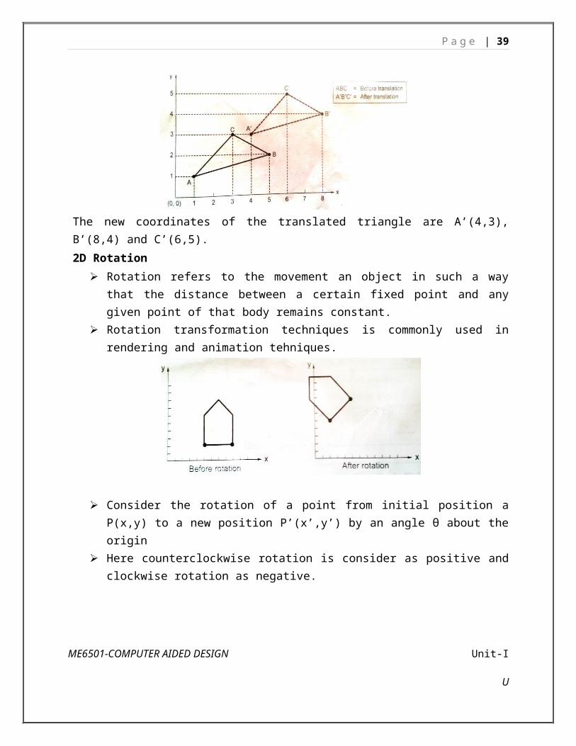
The new coordinates of the translated triangle are A’(4,3), B’(8,4) and C’(6,5).
2D Rotation
Rotation refers to the movement an object in such a way that the distance between a certain fixed point and any given point of that body remains constant.
Rotation transformation techniques is commonly used in rendering and animation tehniques.
Consider the rotation of a point from initial position a P(x,y) to a new position P’(x’,y’) by an angle θ about the origin
Here counterclockwise rotation is consider as positive and clockwise rotation as negative.
ME6501-COMPUTER AIDED DESIGN Unit-I
U

P a g e | 28
Mathematically, the coordinates of P’ are given by
X’ = r cos (α+θ) = r cos α cos θ – r sin α sin θ
Y’ = r sin (α+θ) = r sin α cos θ + r cos α sin θ
Substituting x = r cos α and y = r sin α into the equations gives
X’ = x cos θ – y sin θ
Y’ = x cos θ + y sin θ
2D Scaling
Scaling is the transformation used to change, increase or decrease, the size of an object. Scaling can be achieved by multiplying the original coordinates of an object by the
scaling factor Sx along x-direction and Sy along y-direction. Scaling factor is always positive, if scaling factor is less than 1, the object is
compressed; if more than 1, the object is stretched. If scale factors are equal i.e., Sx=Sy=S, the object changes in size only and not in shape.
This scaling is known as uniform scaling. If scale factors are different i.e., Sx≠Sy, the object changes in size only and not in shape.
This scaling is known as non-uniform scaling.
ME6501-COMPUTER AIDED DESIGN Unit-I
U

P a g e | 29
ME6501-COMPUTER AIDED DESIGN Unit-I
U

P a g e | 30
Example:If a triangle A(1,1), B(3,1), C(1,3) is scaled by a factor 2, find the new coordinates of the triangle.Given: A(1,1), B(3,1), C(1,3); uniform scale factor =2, the effect of scling is represented graphically in Fig.
2D reflection Reflection is a transformation in which the direction of one axis is reversed. Reflection transformation produces a mirror image of an object. The reflection transformation is useful in the construction of symmetric objects. If the
object is symmetric with respect to plane, only half of the geometry is created and then the half model is copied by reflection to develop the full model.
P’=M.P
M=± m11 0 0
0 ± m22 00 0 ± m33
ME6501-COMPUTER AIDED DESIGN Unit-I
U
P a g e | 31
Reflection about x axis:
M=1 0 00 −1 00 0 1
Reflection about y axis:
M=−1 0 00 1 00 0 1
Reflection about xy plane (origin):
M=−1 0 00 −1 00 0 1
ME6501-COMPUTER AIDED DESIGN Unit-I
U

P a g e | 32
In scaling transformation, the original coordinates of an object are multiplied by the given scale factor. There are two types of scaling transformations: uniform and non-uniform. In the uniform scaling, the coordinate values change uniformly along the x, y, and z coordinates, whereas, in non-uniform scaling, the change is not necessarily the same in all the coordinate directions.Let us consider some typical cases
Case 1: a=d=1 and b=c=0 – No Change (identity) Case 2: d=1, b=c=0 – Scaling in x coordinate Case 3: b=c=0 – Scaling in both x and y coordinates
Case 4; a=d =|s|>1 – Enlargement of the original entity Case 5: 0<a=d=|s|<1 – Compression of the entity
Case 6: b=c=0, a=1,d=-1 – Reflection about x- axis Case 7: b=c=0, a=-1,d=1 – Reflection about y- axis Case 8: b=c=0, a=d<0 – Reflection about the origin
ME6501-COMPUTER AIDED DESIGN Unit-I
U

P a g e | 33
Homogeneous Coordinates
Each of the above transformations with the exception of translation can be represented as a row vector X, Y and a 2 X 2 matrix. However, all the four transformations discussed above can be represented as a product of a 1 X 3 row vector and an appropriate 3 X 3 matrix. The conversion of a two-dimensional co-ordinate pair (X, Y) into a 3-dimensional vector can be achieved by representing the point as [X Y 1].
After multiplying this vector by a 3 X 3 matrix, another homogeneous row vector is obtained [X1 Y1 1]. The first two terms in this vector are the co-ordinate pair which is the transform of (X, Y). This three dimensional representation of a two dimensional plane is called homogeneous co- ordinates and the transformation using the homogeneous co-ordinates is
ME6501-COMPUTER AIDED DESIGN Unit-I
U
P a g e | 34
called homogeneous transformation.
10. Explain the concept of 3D transformation. (JAN 2014)A three-dimensional object has a three-dimensional geometry, and therefore,
it requires a three-dimensional coordinate transformation. A right handed coordinate system is used to carry out a 3-D transformation.
The scaling and translation transformations are essentially the same as two- dimensional transformations. However, the points matrix will have a non-zero 3rd column. Additionally, the transformation matrices contain some non-zero values in the third row and third column.
Translation
In three-dimensional homogeneous coordinate representation, a point is transformed from position P(x,y,z) to P’= (x’,y’,z’) this can be written as:
x’ = x+ tx
y’ = y+ ty
z’ = z+ tz
P’=T.P
Rotation
ME6501-COMPUTER AIDED DESIGN Unit-I
U

P a g e | 35
Parallel to one of the Coordinate Axis
In special cases where an object is to be rotated about an axis that is parallel to one of the coordinate axis, we can obtain the desired rotation with the following transformation sequence.
1. Translate the object so that the rotation axis coincides with the parallel coordinate axis (for simplicity, let us take x-axis).
2. Perform the specified rotation about that axis.3. Translate the object so that the rotation axis is moved back to its original position.
ME6501-COMPUTER AIDED DESIGN Unit-I
U

P a g e | 36
Scaling
The matrix expression for the scaling transformation of a position P = (x, y, z) relative to coordinate origin can be written
ME6501-COMPUTER AIDED DESIGN Unit-I
U

P a g e | 37
The matrix representation for an arbitrary fixed-point (xf, yf, zf) can be expressed as:
Reflection
The matrix expression for the reflection transformation of a position P = (x, y, z) relative to x-y plane can be written as:
ME6501-COMPUTER AIDED DESIGN Unit-I
U

P a g e | 38
Transformation matrices for inverting x and y values are defined similarly, as reflections relative to yz plane and xz plane, respectively.
Shears:
The matrix expression for the shearing transformation of a position P = (x, y, z), t produce z-axis shear, can be written as:
• Parameters a and b can be assigned any real values. The effect of this transformation is to alter x- and y- coordinate values by an amount that is proportional to the z value, while leaving the z coordinate unchanged.
• Shearing transformations for the x axis and y axis are defined similarly.
11. Explain computer graphics. (Or) What is meant by Interactive Computer Graphics? Explain its various elements. (Nov 08)
Traditionally drawings are prepared on plane drawing sheets. This has several limitations. The sketches have to be made only in two dimensions. Though the depth can be represented by pictorial projections like isometric and perspective projections, the projections have to be necessarily reduced to two dimensions.
ME6501-COMPUTER AIDED DESIGN Unit-I
U
P a g e | 39
Use of computer graphics has opened up tremendous possibilities for the designer. Some of them are listed below:
The object is represented by its geometric model in three dimensions (X, Y and Z). The mathematical representation reduces creation of views like orthographic, isometric,
axonometric or perspective projections into simple viewing transformations. Though the size of the screen is limited, there is no need to scale the drawings. Drawings can be made very accurate. The geometric models can be represented in color and can be viewed from any angle. Sections can be automatically created. The associativity ensures that any change made in one of the related views will
automatically reflect in other views. Revision and revision control are easy. Drawings (geometric models) can be modified easily. More important than all, drawings can be reused conveniently. Storage and retrieval of drawings are easy.
Modern computer graphics displays are simple in construction. They consist of basically three components.i. Monitorii. Digital Memory or Frame Buffer iii. Display ControllerMost of the computer graphics displays use raster CRT which is a matrix of discrete cells each of which can be made bright. A graphic entity like line or circle is represented as a series of “points or dots” on the screen. Therefore, it is called as a point plotting device.
The video display screen is divided into very small rectangular elements called a picture element or pixel. This happens to be the smallest addressable screen element. Graphic images are formed by setting suitable intensity and color to the pixels which compose the image.
Depending upon the resolution screens may have varying number of pixels. For example, an SVGA monitor with a resolution of 1024 x 768 will have 1024 pixels in every row (X - direction) and 768 pixels in every column (Y-direction). Monitors of larger size will have resolution of 1024 x 1024 or more. A raster scan system displays the image on a CRT in a certain fixed sequence.
The refresh rate is the number of complete images or frames scanned per second. In the case of interlaced refresh cycle odd numbered raster lines are refreshed during 1/60th of a second. Even numbered raster lines are refreshed during the next 1/60th of a second. In non-interlaced displays, all lines are refreshed in 1/60th of a second. The quality of non- interlaced display is hence, superior. These systems, however, require expensive frame buffer memory and display controller.
ME6501-COMPUTER AIDED DESIGN Unit-I
U

P a g e | 40
Graphic PrimitivesA drawing is created by an assembly of points, lines, arcs, circles. For example,
drawing shown in Fig consists of several entities. In computer graphics also drawings are created in a similar manner. Each of these is called an entity.
The drawing entities that a user may find in a typical CAD package include : point line, construction line, multi-line, polyline,circle spline, arc ellipse polygon, rectangle.
A simple drawingGraphics System
Graphics system consists of four subsystems:a. Geometry engine subsystem b. Scan conversion subsystemc. Raster subsystemd. Display subsystemThese subsystems are shown in Fig schematically.
GE OM E TRY
SCAN CONVERSIO N
RASTER
DISPLAY
Subsystems of a Graphics Engine
Geometry Engine
The geometry engine accepts 3-D world co-ordinate data and converts them into X, Y screen co-ordinates. Depth information is manipulated using Z-buffer. Colors are also processed. The geometry pipeline facilitates among other functions lighting, clipping, and 3D to 2D projection, viewing transformations, rotation, scaling and
ME6501-COMPUTER AIDED DESIGN Unit-I
U

P a g e | 41
translation.
Scan Conversion
The scan conversion subsystem carries out polygon decomposition, edge slope calculations, span slope calculations and span interpolation. The output of the scan conversion is the pixel information to the raster subsystem.
Raster Subsystem
The raster subsystem will have usually 24 bit planes. This will provide eight bit planes for each primary color (RGB) so that (28) shades of a single color can thus obtain.Since the different colors are obtained by the three primary colors a total of (28)3colors are available on the screen.In a typical raster engine five 256K X 4D RAM provide 4 bits of Z-depth. The raster information is stored in the frame buffer. Twenty 64 K X 4 video RAM provide 4 bits for each pixel of 1280 X 1024 resolution. Entry level systems will have 12 bit planes and high end systems will have 32 bit planes for the frame buffer. These provide the color and depth for the images.
Display Subsystem
The display subsystem has multi-mode graphics processors which manage the display, send the Red, Green, Blue color (RGB) data to the respective digital to analog converters as well as provide a video output.
12. Write short notes on clipping, view ports, line drawing. (JAN 2014) (Or)Explain the Cohen - Sutherland line-clipping approach with proper sketches. (M.E. JAN 2010)
Clipping
Clipping is the process of determining the visible portions of a drawing lying within a window. In clipping each graphic element of the display is examined to determine whether or not it is completely inside the window, completely outside the window or crosses a window boundary.
Portions outside the boundary are not drawn. If the element of a drawing crosses the boundary the point of inter-section is determined and only portions which lie inside are drawn. Readers are advised to refer to books on computer graphics for typical clipping algorithms like Cohen-Sutherland clipping algorithm. Fig shows an example of clipping.
ME6501-COMPUTER AIDED DESIGN Unit-I
U

P a g e | 42
There is something missing between projection and viewing. Before projecting, we need to eliminate the portion of scene that is outside the viewing
frustum
Modify end points of lines to lie in rectangle
Method: Is end-point inside the clip region - half-plane tests–If outside, calculate intersection between the line and the clipping rectangle and make this the new end point
Both endpoints inside: trivial accept One inside: find intersection and clip Both outside: either clip or reject (tricky case)
Cohen-Sutherland Algorithm
ME6501-COMPUTER AIDED DESIGN Unit-I
U

P a g e | 43
• Uses outcodes to encode the half-plane tests results
Rules:– Trivial accept: outcode(end1) and outcode (end2) both zero– Trivial reject: outcode(end1) & (bitwise and) outcode (end2)Nonzero Else subdivideIf neither trivial accept nor reject:–Pick an outside endpoint (with nonzero outcode)–Pick an edge that is crossed (nonzero bit of outcode)–Find line's intersection with that edge–Replace outside endpoint with intersection point–Repeat until trivial accept or reject
Polygon clippingConvert a polygon into one or more polygons that form the intersection of the
original with the clip window.
ME6501-COMPUTER AIDED DESIGN Unit-I
U

P a g e | 44
Sutherland-HodgmanPolygon Clipping Algorithm
Subproblem:
Clip a polygon (vertex list) against a single clip plane
Output the vertex list(s) for the resulting clipped polygon(s)
• Clip against all four planes–generalizes to 3D (6 planes)–generalizes to any convex clip polygon/polyhedronTo clip vertex list against one half-plane:• if first vertex is inside - output it• loop through list testing inside/outside transition - outputdepends on transition: in-to-in: output vertex out-to-in: output intersection and vertex out-to-out: no output in-to-out: output intersection
View port
Drawing of Lines
Straight line segments are used a great deal in computer generated pictures. The following criteria have been stipulated for line drawing displays:
i. Lines should appear straightii. Lines should terminate accuratelyiii. Lines should have constant densityiv. Line density should be independent of length and anglev. Line should be drawn rapidly
The process of turning on the pixels for a line segment is called vector generation. If the end points of the line segment are known, there are several schemes for selecting the pixels between the end pixels. One method of generating a line segment is a symmetrical digital differential
ME6501-COMPUTER AIDED DESIGN Unit-I
U

P a g e | 45
analyzer (DDA).
ME6501-COMPUTER AIDED DESIGN Unit-I
U
![Unit 1 Physics Notes[1]](https://static.fdocuments.us/doc/165x107/547accd0b37959582b8b4b35/unit-1-physics-notes1.jpg)