
UNIT 1- Module 1 INTRODUCTION OF ADDITIVE …A prototype of supersonic aircraft. Types of...
9
Additive Manufacturing Unit-I; Mod 1 1 Singuru Rajesh, Asst.Prof, Raghu Engineering College UNIT 1- Module 1 INTRODUCTION OF ADDITIVE MANUFACTURING Syllabus: Introduction: Prototyping fundamentals, historical development, fundamentals of rapid prototyping, advantages and limitations of rapid prototyping, commonly used terms, classification of RP process. Textbook: RAPID PROTOTYPING: PRINCIPLES AND APPLICATIONS by Chua C.K., Leong K.F. and LIM C.S. =======XXXXX======= INTRODUCTION Subtractive Machining Processes: Milling, turning, drilling, planning, sawing, grinding, EDM, laser cutting, Water Jet Machining etc… Additive Manufacturing: Stereo-lithography and Selective Laser Sintering Formative Manufacturing Process: Bending, forging, electromagnetic forming and plastic injection moulding Fig1. Different types of Manufacturing Process Additive Manufacturing (AM) refers to a process by which digital 3D design data is used to build up a component in layers by depositing material. (From the International Committee F42 for Additive Manufacturing Technologies, ASTM) Example: Stereo-lithography and Selective Laser Sintering Fig 2. Additive Manufacturing Process Examples
Transcript of UNIT 1- Module 1 INTRODUCTION OF ADDITIVE …A prototype of supersonic aircraft. Types of...

Additive Manufacturing Unit-I; Mod 1
1 Singuru Rajesh, Asst.Prof, Raghu Engineering College
UNIT 1- Module 1
INTRODUCTION OF ADDITIVE MANUFACTURING
Syllabus:
Introduction: Prototyping fundamentals, historical development, fundamentals of rapid
prototyping, advantages and limitations of rapid prototyping, commonly used terms,
classification of RP process.
Textbook: RAPID PROTOTYPING: PRINCIPLES AND APPLICATIONS by Chua C.K.,
Leong K.F. and LIM C.S.
=======XXXXX=======
INTRODUCTION
Subtractive Machining Processes: Milling, turning, drilling, planning, sawing, grinding,
EDM, laser cutting, Water Jet Machining etc…
Additive Manufacturing: Stereo-lithography and Selective Laser Sintering
Formative Manufacturing Process: Bending, forging, electromagnetic forming and plastic
injection moulding
Fig1. Different types of Manufacturing Process
Additive Manufacturing (AM) refers to a process by which digital 3D design data is used to
build up a component in layers by depositing material. (From the International Committee
F42 for Additive Manufacturing Technologies, ASTM)
Example: Stereo-lithography and Selective Laser Sintering
Fig 2. Additive Manufacturing Process Examples

Additive Manufacturing Unit-I; Mod 1
2 Singuru Rajesh, Asst.Prof, Raghu Engineering College
Additive Manufacturing (AM) also refers as 3D Printing, Rapid Prototyping.
Why for Additive Manufacturing?
Product Customization can be possible
Part Complexity products can be produced
Wide range of Materials
More Speed
Part Quantity can be increased
Cost can be reduced
Fig. 2 Different components made with Additive Manufacturing
Prototype is the first or original example of something that has been or will be copied or
developed. It is a model for preliminary version and an approximation of a product (or system)
or its components in some form for a definite purpose in its implementation. A prototype is
an important and vital part of the product development process
e.g.: A prototype of supersonic aircraft.
Types of Prototypes:
1. The implementation of the prototype from the entire product (or system) itself to its
sub-assemblies and components…
2. The form of the prototype from a virtual prototype to a physical prototype…
3. The degree of the approximation of the prototype from a very rough representation to
an exact replication of the product.
1. The implementation aspect of the prototype covers the range of prototyping the complete
product (or system) to prototyping part of, or a sub-assembly or a component of the product.

Additive Manufacturing Unit-I; Mod 1
3 Singuru Rajesh, Asst.Prof, Raghu Engineering College
An example of such a prototype is a test platform that is used to find the comfortable rest angles
of an office chair that will reduce the risk of spinal injuries after prolonged sitting on such a
chair.
2. Virtual prototypes that refers to prototypes that are nontangible, usually represented in
some form other than physical, e.g. mathematical model of a control system. The second
aspect of the form of the prototype takes into account how the prototype is being
implemented.
An example is the visualization of airflow over an aircraft wing to ascertain lift and drag on
the wing during supersonic flight.
3. It covers the degree of approximation or representativeness of the prototype. On one hand,
the model can be a very rough representation of the intended product, like a foam model,
to study the general form and enveloping dimensions of the product in its initial stage of
development. On the other hand, the prototype can be an exact full scale exact replication
of the product that models every aspects of the product
An example of this is the building of catches with different material to find the right “clicking”
sound for a cassette player door.
Roles of prototypes play in the product development process are several. They include the
following: (1) Experimentation and learning (2) Testing and proofing (3) Communication and
interaction (4) Synthesis and integration (5) Scheduling and markers
Rapid prototyping typically falls in the range of a physical prototype, usually are fairly accurate
and can be implemented on a component level or at a system level.
Rapid Prototyping of physical parts, or otherwise known as solid freeform fabrication or
desktop manufacturing or layer manufacturing technology, represents the third phase in the
evolution of prototyping.
History of Additive Manufacturing (Rapid Prototyping):
Fig 3. History of Rapid Prototyping

Additive Manufacturing Unit-I; Mod 1
4 Singuru Rajesh, Asst.Prof, Raghu Engineering College
PHASES OF PROTOTYPING
Prototyping or model making in the traditional sense is an age-old practice. The fabrication
of prototypes is experimented in many forms — material removal, castings, moulds, joining
with adhesives etc. and with many material types — aluminium, zinc, urethanes, wood, etc.
Prototyping processes have gone through three phases of development, the last two of which
have emerged only in the last 20 years. Like the modeling process in computer graphics [8],
the prototyping of physical models is growing through its third phase.
i. First Phase: Manual Prototyping
ii. Second Phase: Soft or Virtual Prototyping
iii. Third Phase: Rapid Prototyping
FUNDAMENTALS OF RAPID PROTOTYPING
Additive Manufacturing Unit-I; Mod 1
5 Singuru Rajesh, Asst.Prof, Raghu Engineering College
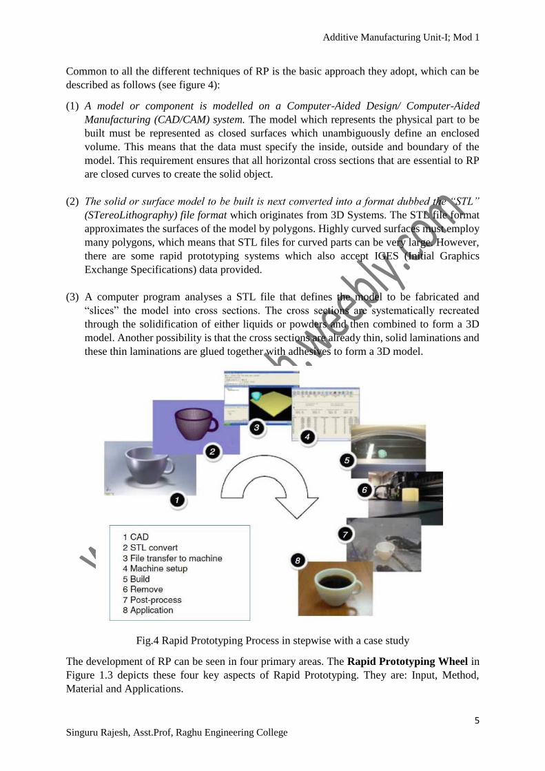
Common to all the different techniques of RP is the basic approach they adopt, which can be
described as follows (see figure 4):
(1) A model or component is modelled on a Computer-Aided Design/ Computer-Aided
Manufacturing (CAD/CAM) system. The model which represents the physical part to be
built must be represented as closed surfaces which unambiguously define an enclosed
volume. This means that the data must specify the inside, outside and boundary of the
model. This requirement ensures that all horizontal cross sections that are essential to RP
are closed curves to create the solid object.
(2) The solid or surface model to be built is next converted into a format dubbed the “STL”
(STereoLithography) file format which originates from 3D Systems. The STL file format
approximates the surfaces of the model by polygons. Highly curved surfaces must employ
many polygons, which means that STL files for curved parts can be very large. However,
there are some rapid prototyping systems which also accept IGES (Initial Graphics
Exchange Specifications) data provided.
(3) A computer program analyses a STL file that defines the model to be fabricated and
“slices” the model into cross sections. The cross sections are systematically recreated
through the solidification of either liquids or powders and then combined to form a 3D
model. Another possibility is that the cross sections are already thin, solid laminations and
these thin laminations are glued together with adhesives to form a 3D model.
Fig.4 Rapid Prototyping Process in stepwise with a case study
The development of RP can be seen in four primary areas. The Rapid Prototyping Wheel in
Figure 1.3 depicts these four key aspects of Rapid Prototyping. They are: Input, Method,
Material and Applications.

Additive Manufacturing Unit-I; Mod 1
6 Singuru Rajesh, Asst.Prof, Raghu Engineering College
Fig.5 Rapid Prototyping Wheel
ADVANTAGES OF RAPID PROTOTYPING
The benefits of RP systems are immense and can be categorized into direct and indirect
benefits.
•Product Designers
•Tooling and Manufacturing Engineer
Direct Benfits
•Marketing
•ConsumerIndirect Benfits

Additive Manufacturing Unit-I; Mod 1
7 Singuru Rajesh, Asst.Prof, Raghu Engineering College
Fig.6. Integration of Rapid Prototyping Technology with in product cycle. The figure results
that depending on the size of production, savings on time and cost could range from 50% up
to 90%.
Fig. 7 Current and Potential industries for Additive Manufacturing

Additive Manufacturing Unit-I; Mod 1
8 Singuru Rajesh, Asst.Prof, Raghu Engineering College
CLASSIFICATION OF RAPID PROTOTYPING
Classification of RP systems broadly by the initial form of its material, i.e. the material that the
prototype or part is built with. In this manner, all RP systems can be easily categorized into (i)
Liquid based RP, (ii) Solid based RP and (iii) Powder based RP
1. Liquid-based RP systems have the initial form of its material in liquid state. Through a
process commonly known as curing, the liquid is converted into the solid state. The below
RP systems with the exception of (2), (11), (13) and (14). Cubital (2) and Light Sculpting
(11) use the masked lamp method, while the two laser beam method is still not
commercialized. Rapid Freeze (13) involves the freezing of water droplets and deposit in a
manner much like FDM to create the prototype.
(1) 3D Systems’ Stereolithography Apparatus (SLA)
(2) Cubital’s Solid Ground Curing (SGC)
(3) Sony’s Solid Creation System (SCS)
(4) CMET’s Solid Object Ultraviolet-Laser Printer (SOUP)
(5) Autostrade’s E-Darts
(6) Teijin Seiki’s Soliform System
(7) Meiko’s Rapid Prototyping System for the Jewelry Industry
(8) Denken’s SLP
(9) Mitsui’s COLAMM
(10) Fockele & Schwarze’s LMS
(11) Light Sculpting
(12) Aaroflex
(13) Rapid Freeze
(14) Two Laser Beams
(15) Microfabrication
2. Solid-based RP systems are meant to encompass all forms of material in the solid state.
In this context, the solid form can include the shape in the form of a wire, a roll, laminates
and pellets. In the below RP systems (1), (3), (4) and (9) belong to the Cutting and
Glueing/Joining method, while the Melting and Solidifying/Fusing method used RP
systems (2), (5), (6), (7) and (8).
1. Cubic Technologies’ Laminated Object Manufacturing (LOM)
2. Stratasys’ Fused Deposition Modeling (FDM)
3. Kira Corporation’s Paper Lamination Technology (PLT)
4. 3D Systems’ Multi-Jet Modeling System (MJM)
5. Solidscape’s Model Maker and Pattern Master
6. Beijing Yinhua’s Slicing Solid Manufacturing (SSM)
7. Melted Extrusion Modeling (MEM) and
8. Multi-Functional RPM Systems (M-RPM)
3. In a Powder-based RP the material will be in powder is by-and-large in the solid state.
However, it is intentionally created as a category outside the solid-based RP systems to
mean powder in grain-like form. All the below RP systems employ the Joining/Binding
method. The method of joining/binding differs for the above systems in that some employ
a laser while others use a binder/glue to achieve the joining effect.
1. 3D Systems’s Selective Laser Sintering (SLS)
2. Z Corporation’s Three-Dimensional Printing (3DP)

Additive Manufacturing Unit-I; Mod 1
9 Singuru Rajesh, Asst.Prof, Raghu Engineering College
3. EOS’s EOSINT Systems
4. Optomec’s Laser Engineered Net Shaping (LENS)
5. Soligen’s Direct Shell Production Casting (DSPC)
6. Fraunhofer’s Multiphase Jet Solidification (MJS)
7. Acram’s Electron Beam Melting (EBM)
8. Aeromet Corporation’s Lasform Technology
9. Precision Optical Manufacturing’s Direct Metal Deposition (DMDTM)
10. Generis’ RP Systems (GS)
11. Therics Inc.’s Theriform Technology
12. Extrude Hone’s PrometalTM 3D Printing Process
==============XXXXXXX===============
Prepared by
SINGURU RAJESH M.Tech (MD), PGDEEM, B.Tech (ME)
Assistant Professor
Raghu Engineering College(Autonomous)
Dakamarri, Bhimunipatnam Mandal,
Visakapatnam Dist, Andhra Pradesh.
www.crazymech.weebly.com