Unique Swing Span Design Bridges-Unique... · Unique Swing Span Design for the St. Ann Bridge in...
31
LEE HUPPERICH, P.E. MECHANICAL ENGINEER Unique Swing Span Design for the St. Ann Bridge in Houma, Louisiana
Transcript of Unique Swing Span Design Bridges-Unique... · Unique Swing Span Design for the St. Ann Bridge in...

L E E H U P P E R I C H , P . E .
M E C H A N I C A L E N G I N E E R
Unique Swing Span Design for the St. Ann Bridge in Houma, Louisiana

Presentation Overview
I. Project Location and General Information II. Former St. Ann Bridge III. New St. Ann Bridge a. Bridge Type & Design Criteria b. Structural Design Features c. Mechanical Design Features IV. Field Photographs V. Construction Cost VI. Partners

I. Project Location & General Information
S.P. No. H.006318 (713-55-0100)
St. Ann Bridge Replacement Over Bayou Terrebonne, Terrebonne Parish, Houma LA
Federal Aid Off-System Highway Bridge Program
Bridge Site Bridge Site

II. Former St. Ann Bridge
The former St. Ann bridge was a 118’ single lane, equal arm swing bridge, circa 1960. The bridge deck is
supported by a center pylon with steel stay rods attached to the floor beams. The sub-structure consists of
timber piles and timber bents.

II. Former St. Ann Bridge
- Single lane with no shoulders
- Timber deck with steel plate runners
- 5 ton posting
- Number of openings: 0-30 per year.

III. New St. Ann Bridge
Plan – New Swing Span and Approaches Design Directives
90’-0” (60’/30’) unequal arm swing span bridge on a new alignment.
35’-0” horizontal clearance for marine navigation.
30’-0” clear roadway (two 12’-0” traffic lanes, two 3’-0” shoulders).
Minimal control system - infrequently operated bridge.
Movable traffic barriers (vertical type).

III a. New St. Ann Bridge
Design Specifications
AASHTO Standard Specifications for Highway Bridges, 2002.
AASHTO Standard Specifications for Movable Bridges, 1988.
Construction Specifications
LADOTD Standard Specifications for Roads and Bridges, 2006.
Elevations
Datum used - NAVD 88.
Design Criteria
Live load HS-20-44 Truck or Lane Load, HS-18 Truck.
Profile – New Swing Span and Approaches

III b. Structural - Framing

III b. Structural - Pivot Girder
Unique Structural Elements
- Double Pivot Girder
- No Center Wedges
- Counterweights placed on the
west main girder to offset the weight
of the access platform & HPU weight

III b. Structural – Shop Assembly

III c. Machinery Layout
PLAN – MACHINERY LAYOUT

III c. Movable Traffic Barriers
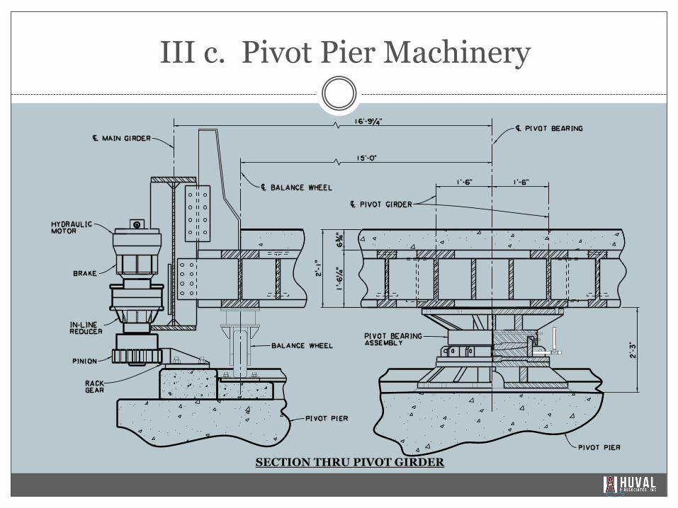
III c. Pivot Pier Machinery
SECTION THRU PIVOT GIRDER

III c. Pivot Bearing
PIVOT BEARING ASSEMBLY
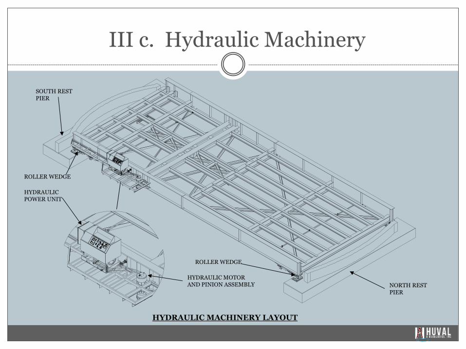
III c. Hydraulic Machinery
NORTH REST PIER
SOUTH REST PIER
HYDRAULIC MOTOR AND PINION ASSEMBLY
HYDRAULIC POWER UNIT
ROLLER WEDGE
ROLLER WEDGE
HYDRAULIC MACHINERY LAYOUT

III c. HPU & Controls
(HPU) – TOP VIEW
HPU & MOTOR ASSEMBLY
VIEW A-A: ELECTRICAL PANEL

III c. Control Panel
CONTROL PANEL LAYOUT
Hydraulic System:
Hydraulic Motor : SAI GM3 – 1000 Radial Piston Type
Hydraulic Displacement : 1.369 gal/rev
Max Flow Rate: 20 gpm
HPU System Pressure (Compensator Pressure) = 2,200 psig
Operating Pressure – Roller Wedges = 500 – 1,000 psig
Operating Pressure – Span Drive Motor = 900 – 1,800 psig
All hydraulic equipment rated for a minimum of 3,000 psi
Electric Motor:
30 hp Squirrel Cadge Induction Motor TEFC
In-Line Gear Reducer:
5.25:1 Reduction
Pinion Velocity:
13.88 rpm
Span Velocity:
0.58 rpm

III c. Shop Testing Hydraulic Machinery

IV. New St. Ann Bridge – East Elevation

IV. New St. Ann Bridge – Open Position

IV. Hydraulic Motor, Gear Reducer, Brake & Pinion

IV. HPU – Control Panel & HPU Access

IV. Counterweight & South Rest Pier

IV. New St. Ann Bridge – West Elevation

IV. New St. Ann Bridge - Roller Wedge

IV. New St. Ann Bridge - Pivot Pier

IV. New St. Ann Bridge - Pivot Bearing

IV. New St. Ann Bridge - Site Plan
V. Construction Cost
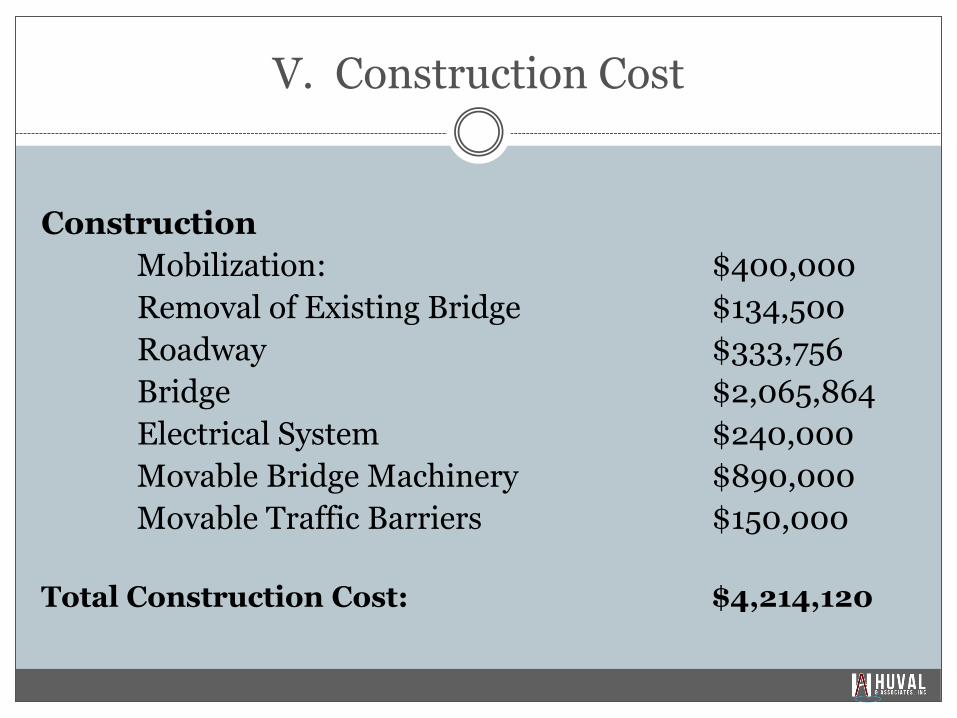
Construction
Mobilization: $400,000
Removal of Existing Bridge $134,500
Roadway $333,756
Bridge $2,065,864
Electrical System $240,000
Movable Bridge Machinery $890,000
Movable Traffic Barriers $150,000
Total Construction Cost: $4,214,120

VI. Design and Construction Partners
Design was completed in 2010 & let on June 29, 2011.
Construction was completed in early 2014.
Project Manager: Gary Pentek, P.E. (LaDOTD)
Road Design: James Ledet, P.E. (T. Baker Smith)
Structural Design: Colby Guidry, P.E. (Huval)
Mechanical & Electrical Design: Malcolm Huval, P.E. (Huval)
Pier Review & CRES: Lee Hupperich, P.E. (Huval)
Project Engineer: Larry Langenstein (ECM)
Contractor: Van Bailey & John Housey (Coastal Bridge Co.)
Fabricators:
Hydraulic Machinery: Supreme Integrated Technology
Bridge Structural Steel & Machinery: Hardie-Tynes
Electrical System: Coastal Bridge Co.

L E E H U P P E R I C H , P E
M E C H A N I C A L E N G I N E E R
3 3 7 / 3 0 3 - 8 6 6 7
l h u p p e r i c h @ h u v a l a s s o c . c o m
w w w . h u v a l a s s o c . c o m
Thank you