
Uninterruptible Power Supply Unit for Universal Use...
36
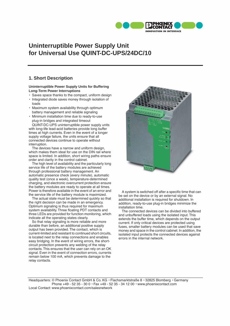
1. Short Description Uninterruptible Power Supply Units for Buffering Long-Term Power Interruptions • Saves space thanks to the compact, uniform design • Integrated diode saves money through isolation of loads • Maximum system availability through optimum battery management and reliable signaling • Minimum installation time due to ready-to-use plug-in bridges and integrated timeout QUINT-DC-UPS uninterruptible power supply units with long-life lead-acid batteries provide long buffer times at high currents. Even in the event of a longer supply voltage failure, the units ensure that all connected devices continue to operate without interruption. The devices have a narrow and uniform design, which makes them ideal for use on the DIN rail where space is limited. In addition, short wiring paths ensure order and clarity in the control cabinet. The high level of availability and the particularly long service life of the battery modules are achieved through professional battery management. An automatic presence check (every minute), automatic quality test (once a week), temperature-determined charging, and electronic overcurrent protection ensure the battery modules are ready to operate at all times. Power is therefore available in the event of an error and the service life of the battery module is maximized. The actual state must be determined quickly so that the right decision can be made in an emergency. Optimum signaling is thus required for maximum system availability. Three floating PDT contacts and three LEDs are provided for function monitoring, which indicate all the operating states clearly. So that relay signaling is more reliable and more durable than before, an additional positive supply output has been provided. The contact, which is current-limited and resistant to continued short circuits, is located next to the relay connections and enables easy bridging. In the event of wiring errors, the short- circuit protection prevents any welding of the relay contacts. This ensures that the user can rely on an OK signal. Even in the event of connection errors, currents remain below 100 mA, which prevents damage to the relay contacts. A system is switched off after a specific time that can be set on the device or by an external signal. No additional installation is required for shutdown. In addition, ready-to-use plug-in bridges minimize the installation time. The connected devices can be divided into buffered and unbuffered loads using the isolated input. This extends the buffer time, which depends on the output current. If only critical devices are protected using fuses, smaller battery modules can be used that save money and space in the control cabinet. In addition, the isolated input protects the connected devices against errors in the internal network. Uninterruptible Power Supply Unit for Universal Use QUINT-DC-UPS/24DC/10 Headquarters: © Phoenix Contact GmbH & Co. KG • Flachsmarktstraße 8 • 32825 Blomberg • Germany Phone +49 - 52 35 - 30 0 • Fax +49 - 52 35 - 34 12 00 • www.phoenixcontact.com Local Contact: www.phoenixcontact.com/salesnetwork
Transcript of Uninterruptible Power Supply Unit for Universal Use...
Uninterruptible Power Supply Unitfor Universal Use QUINT-DC-UPS/24DC/10
1. Short Description
Uninterruptible Power Supply Units for Buffering Long-Term Power Interruptions• Saves space thanks to the compact, uniform design• Integrated diode saves money through isolation of
loads• Maximum system availability through optimum
battery management and reliable signaling• Minimum installation time due to ready-to-use
plug-in bridges and integrated timeoutQUINT-DC-UPS uninterruptible power supply units
with long-life lead-acid batteries provide long buffer times at high currents. Even in the event of a longer supply voltage failure, the units ensure that all connected devices continue to operate without interruption.
The devices have a narrow and uniform design, which makes them ideal for use on the DIN rail where space is limited. In addition, short wiring paths ensure order and clarity in the control cabinet.
The high level of availability and the particularly long service life of the battery modules are achieved through professional battery management. An automatic presence check (every minute), automatic quality test (once a week), temperature-determined charging, and electronic overcurrent protection ensure the battery modules are ready to operate at all times. Power is therefore available in the event of an error and the service life of the battery module is maximized.
The actual state must be determined quickly so that the right decision can be made in an emergency. Optimum signaling is thus required for maximum system availability. Three floating PDT contacts and three LEDs are provided for function monitoring, which indicate all the operating states clearly.
So that relay signaling is more reliable and more durable than before, an additional positive supply output has been provided. The contact, which is current-limited and resistant to continued short circuits, is located next to the relay connections and enables easy bridging. In the event of wiring errors, the short-circuit protection prevents any welding of the relay contacts. This ensures that the user can rely on an OK signal. Even in the event of connection errors, currents remain below 100 mA, which prevents damage to the relay contacts.
Headquarters: © Phoenix Contact GmbH & Co. KG • FlaPhone +49 - 52 35 - 30 0 • Fax +49 - 52 3
Local Contact: www.phoenixcontact.com/salesnetwork
A system is switched off after a specific time that can be set on the device or by an external signal. No additional installation is required for shutdown. In addition, ready-to-use plug-in bridges minimize the installation time.
The connected devices can be divided into buffered and unbuffered loads using the isolated input. This extends the buffer time, which depends on the output current. If only critical devices are protected using fuses, smaller battery modules can be used that save money and space in the control cabinet. In addition, the isolated input protects the connected devices against errors in the internal network.
chsmarktstraße 8 • 32825 Blomberg • Germany5 - 34 12 00 • www.phoenixcontact.com

PHOENIX CONTACT page 2 of 9
Solid Stranded Torque[mm
2
] AWG [Nm] [lb in]
Input 0.2 - 2.5 0.2 - 2.5 25 - 14 0.5 - 0.6 4.4 - 5.3Output 0.2 - 2.5 0.2 - 2.5 25 - 14 0.5 - 0.6 4.4 - 5.3Signal 0.2 - 2.5 0.2 - 2.5 25 - 14 0.5 - 0.6 4.4 - 5.3
Description
Uninterruptible
power supply unit
with integrated 1.3 Ah battery module
Technical Data
Input Data
Nominal input voltageInput voltage rangeCurrent consumption (No load/charging/maximum)Switching threshold Buffer time Can be configuredInput fuseMaximum power dissipation (Ready/buffer mode)
Output Data
Can be connected in parallel (battery module)
Output Data in Normal Operation
Nominal output voltageOutput voltageOutput currentCurrent limitOverload fuse
Output Data in Buffer Mode
Nominal output voltageOutput voltageOutput currentCurrent limitOverload fuseEfficiencyRemote shutdown
Charging
Charge characteristic curveEnd-of-charge voltageCharge currentTemperature/voltage compensationBattery/presence check/time interval
Memory Medium
Nominal voltageNominal capacityService lifeSelf-dischargeLatest startup after delivery
QUINT-DC-UPS/24DC/10
DC UPS Module
U u F
Type Order No.
Pcs.Pkt.
QUINT-DC-UPS/24DC/10 28 66 22 6
1
24 V DC22.5 - 30 V DC0.1 A/0.5 A/10.5 AU
a
> 22 V; dynamic U
in
- 1 V/0.1 s0.5; 1; 2; 3; 10; 15; 20; 30; continuousInternal, 15 A20 W/8 W
Yes, to increase the buffer time
24 V DCU
in
10 ANoneInternal, 15 A
24 V DC27.9 V DC10 A15 A15 A, internal fuse91%Yes
I/U characteristic curve27 V400 mANo60 seconds
Internal24 V DC1.3 Ah6 years at +20°C (+68°F)< 1 mA9 months at +20°C to +30°C (+68°F to +86°F)9 months at + 30°C to +40°C (+86°F to +104°)F
130
mm
(5
.118
in.)
100 mm (3.937 in.)
125 mm (4.921 in.)
� �
� �
� �
� � � � � � �
�
� � � � � � � �
� � � � � �� � � � � � � �
� �
� �
� �
� �
� �
� �
�����
������
���
����
�! � � �� � � � �
� " � � �
�
�
� � � � � # � � � $ � � � � �
� � � � � � %
&������
�'�
((& �
& �
Uninterruptible Power Supply Unit for Universal Use – QUINT-DC-UPS/24DC/10
2. Technical Data
8 mm
7 mm (0.28 in.)

PHOENIX CONTACT page 3 of 9
Uninterruptible Power Supply Unit for Universal Use – QUINT-DC-UPS/24DC/10
Green LED Red LED, floating PDT,30 V AC/DC, maximum; 1 A, maximumYellow LED, floating PDT,30 V AC/DC, maximum; 1 A, maximumYellow LED, flashing, floating PDT,30 V AC/DC, maximum; 1 A, maximum
EN 60 204 (Surge Voltage Category III)EN 60 950/VDE 0805,UL/C-UL Recognized UL 60 950UL/C-UL Listed UL 508
Germanischer Lloyd EN 50 178 (VDE 0160)
1 kV AC type test1 kV AC routine testOn a horizontal 35 mm (1.378 in.) DIN railEN 60 7151 kV/1 kVIP20II> 500,000 hAluNox (AlMg1), closed(100 x 130 x 125 mm [3.937 x 5.118 x 4.921 in.])1.8 kg
0°C to +50°C (+32°F to +122°F)/0°C to +40°C (+32°F to +104°F)95%, no condensation15 Hz - 150 Hz, 2.3g, 90 minutes
30g23K3
RequirementsEN 61 000-6-2
QUINT-DC-UPS/24DC/10
4 kV8 kV
Level 48 kV15 kV
80 - 1000 MHz10 V/m
Level 380 - 1000 MHz/1.4 - 2.0 GHz10 V/m
2 kV asymmetrical
5)
2 kV asymmetrical
5)
1 kV asymmetrical
5)
4 kV (Level 4)2 kV (Level 3)1 kV (Level 2)
2 kV asymmetrical
5)
2 kV symmetrical
4)
0.5 kV asymmetrical
5)
0.5 kV symmetrical
4)
1 kV asymmetrical
5)
4 kV (Inst. Class 4)2 kV (Inst. Class 4)0.5 kV/(Level 1)0.5 kV/(Level 1)1 kV/(Level 2)
asymmetrical
5)
0.15 - 80 MHz10 V
Level 30.15 - 80 MHz10 V
30% reduction of the input voltage for 0.5 periods
See Input Data:Mains buffering> 20 ms
Class A
6)
Class A
6)
EN 55011 (EN 55022) Class B
7)
EN 55011 (EN 55022) Class B
7)
4)
Symmetrical: Cable to cable.
5)
Asymmetrical: Cable to ground.
6)
Class A: Industrial applications
7)
Class B: Industrial and domestic applications
Signaling
Power In OK Alarm
Battery Mode
Battery Charge
Approvals/Standards
Electrical equipment of machinesElectrical safety (of IT equipment)
Industrial control equipmentShipbuildingElectronic equipment for use in electrical power installations
General Data
Insulation voltageInput/output to housing:
Mounting position
Degree of protectionClass of protection MTBF According to IEC 1709 (SN 29 500)Housing versionDimensions (W x H x D) default upon deliveryWeight Approximately
Climatic Data
Ambient temperature Operation/storageHumidity At +25°C (+77°F)Vibration According to IEC 68-2-6
Shock (in all space directions) According to IEC 68-2-27Pollution degree According to EN 50 178Climatic category According to EN 60 721
cccc
Conformance With EMC Directive 89/336/EECand Low Voltage Directive 73/23/EEC
EMC (Electromagnetic Compatibility)Noise Immunity According to EN 61000-6-2:
Noise Immunity According to EN 61000-6-2
• EN 61000-4-2
3)
Electrostatic discharge(ESD)
HousingContact discharge:
Air discharge:
• EN 61000-4-3
2)
Electromagnetic HF fieldHousing
Frequency:Field strength:
• EN 61000-4-4
3)
Fast transients (burst):Input:
Output:Signal:
• EN 61000-4-5
3)
Input: Surge current loads (surge):
Output:
Signal:
• EN 61000-4-6
2)
Conducted interferenceI/O/S:
Frequency: U
0
:
• EN 61000-4-11
3)
Voltage dipsInput:
Noise Emission According to EN 50081-2
• Radio interference emission EN 55011• Radio interference voltage EN 55011
EN 55011 corresponds to CISPR11/EN 55022 corresponds toCISPR22/EN 61000 corresponds to IEC 1000
2)
Criterion A: Normal operating characteristics within thespecified limits.
3)
Criterion B: Temporary adverse effects on the operatingcharacteristics that the device correctsautomatically.

PHOENIX CONTACT page 4 of 9
1111
DC input, unbuffered
24 V DC input voltage (0.2 mm
2
to 2.5 mm
2
solid) (0.2 mm
2
to 2.5 mm
2
stranded) (25 - 14 AWG) Internal fuse 15 AT
2222
DC output, buffered
24 V DC output voltage (0.2 mm
2
to 2.5 mm
2
stranded) (25 - 14 AWG) The device is idling-proof and short-circuit-proof.
3333
Floating PDT (11,12,13): Alarm
4444
Floating PDT (21,22,23): Battery Mode
5555
Floating PDT (31,32,33): Battery Charge
6666
24 V supply voltage,
maximum current limit 0.2 A for grouped contacts
11, 21, 31
7777
Remote shutdown (R1, R2)
8888
Universal DIN rail adapter UTA 107
9999
Red LED: Alarm
0000
Yellow LED: Battery Mode/Battery
Charge
!!!!
Green LED: Power In OK
"
Buffer time setting 0.5 - 30 minutes
Uninterruptible Power Supply Unit for Universal Use – QUINT-DC-UPS/24DC/10
3. Device View, Connections, and Control Elements
4. Safety Notes and Warning Instructions
To ensure that the device can be operated safely and all functions can be used, please read these instructions carefully.
The QUINT-DC-UPS is a built-in device.
Installation and startup
must only be carried out by qualified personnel. The relevant country-specific regulations (e.g., VDE, DIN) must also be observed.
Before startup it is particularly important to ensure that:• All supply lines have sufficient fuse protection and
are the correct size.• All output cables are the correct size for the maximum
device output current or have separate fuse protection.
• Sufficient convection is ensured.
+ –
DC 24 V 20 A
Input Output
3 14 DCOK + +
13 14 DCOK + +
13 14 DCOK + +
+ –
+24V 0,2A11 21
12 13 211Alarm
Bat.-Mode
Bat.-Charge
QUINT-D
C-UPS/24DC/20
Order-No.: 2
8 66 23 9
Input:
Operational V
oltage:
Output:
24VDC/22A
22.5-30VDC
24VDC/20A
APPROVALS
Read installatio
n instructio
ns
before connecting
- 25 …
+ 70 °C
- 13 …
+ 158 °F
EN 61000-6-2
EN 50081-1
ww
w.in
terfa
ce.p
hoen
ixco
ntac
t.com
U
INDUSTRIAL
CONTROL
EQUIPMENT
43KA
LISTED
–25
FAlarm
Power In O
K
QU
INT
DC
-UPS
20
A
Bat.-Mode
Bat.-Charge
Battery
3 14 DCOK + + –
Alarm
Power InOK
+ –
31 R1 R22 23 32 3321 Bat.-Mode
31 Bat.-Charge
R1 R2Remote
OFFON
1015
5
3
210,5
20
30
∞
tmax[min]
Service≤3,4
≥127,2
Bat.-Select[Ah]
5555
4444
1111
22223333
6666
9999
77778888
$$$$§§§§
""""!!!!
0000
Figure 04

PHOENIX CONTACT page 5 of 9
Uninterruptible Power Supply Unit for Universal Use – QUINT-DC-UPS/24DC/10
5. Installation
5.1. Mounting
The uninterruptible power supply unit together with the battery module can be snapped onto all DIN rails according to EN 60715 and should be mounted horizontally (input terminal blocks facing downwards).
Installation Dimensions
No minimum spacing to other modules is required for proper operation of the device.
5.2. Mounting:
Place the module with the DIN rail guideway on the
top edge
of the DIN rail and then snap it
downwards
.
5.3. Removal:
Release the snap-on catch using a screwdriver and then detach the module from the
bottom edge
of the DIN rail.
+ –
DC 24 V 10 A
Input Output+ –
+24V0,2A31 21 11 12 13
Alarm
Bat.-Mode
Bat.-Charge
QUINT-D
C-UPS/24DC/10
Order-No.: 2
8 66 22 96
Input:
Operational V
oltage:
Output:
Buffer T
ime:
24VDC/10,5A
22.5-30VDC
24VDC/10A
10A/1.5min,2A/20min
APPROVALS
Read installatio
n instructio
ns
before connecting
0 … + 5
0 °C
32 … +122 °F EN 61000-6-2
EN 50081-1
ww
w.in
terfa
ce.p
hoen
ixco
ntac
t.com
U
INDUSTRIAL
CONTROL
EQUIPMENT
43KA
LISTED
FAlarm
Power In O
K
QU
INT
DC
-UPS
10
A
Bat.-Mode
Bat.-Charge
Alarm
Power InOK
22 23 32 33 R1 R2 Bat.-Mode Bat.-Charge
1015
5
3
210,5
20
30
∞
tmax[min]
RemoteOFFON
Pb
Pb
Figure 05
Mounting
Removal
Figure 06

Uninterruptible Power Supply Unit for Universal Use – QUINT-DC-UPS/24DC/10
+ –
DC 24 V 10 A
Input Output+ –
Alarm
Bat.-Mode
Bat.-Charge
Alarm
Power In O
K
QU
INT
DC
-U
Bat.-Mode
Bat.-Charge
Alarm
Power InOK
3 32 33 R1 R2 Bat.-Mode Bat.-Charge
1015
5
3
210,5
20
30
∞
tmax[min]
RemoteOFFON
Figure 08
Figure 07
QUINT-DC-UPS/24DC/10
PowerSupply
+–
AC
DC
UnbufferedLoad
+–
DC
BufferedLoad
Input Output+ – + – + –
5.4. Connection: The device is equipped with COMBICON
connectors. This reliable user-friendly connection method enables quick device connection and visible isolation of the electrical connection, if required.Only operate connectors when the power is switched off.
The following cable cross sections can be connected:
For reliable and safe-to-touch connections: Strip 7 mm (0.28 in.) from the connector ends.
To maintain UL approvals, use copper cables, which are designed for operating temperatures > +75°C (+167°F). To meet GL requirements, unused terminal compartments should be closed.
5.5. Input (1111, Figure 04, Figure 07)The QUINT-DC-UPS is connected to the 24 V DC
output of the power supply via the "Input +" and "Input -" terminal blocks. The output is isolated from the input by the internal diode. The stored power is only supplied to the output. The device is protected against overcurrent and short circuit by an internal input fuse.
FuseFurther device protection is not required, as an
internal fuse is present.
Solid[mm2]
Stranded[mm2]
AWG Torque[Nm]
1111 Input: 0.2 - 2.5 0.2 - 2.5 25 - 14 0.5 - 0.62222 Output: 0.2 - 2.5 0.2 - 2.5 25 - 14 0.5 - 0.63333-7777 Signal: 0.2 - 2.5 0.2 - 2.5 25 - 14 0.5 - 0.6
7 mm (0.28 in.)
PHOENIX CONT
If the internal fuse is blown, this is most probably due to a device fault.In this case, the device should be checked in the factory.
ACT page 6 of 9

Uninterruptible Power Supply Unit for Universal Use – QUINT-DC-UPS/24DC/10
PHOENIX CONTACT page 7 of 9
5.6. Output (2222 Figure 04, Figure 07)All devices that must be supplied without interruption
in the event of a supply voltage failure ("Buffered Load"), are connected to the "Output +" and "Output -" terminal blocks of the DC output (Fig. 07). It is recommended that all other loads, which do not require buffering ("Unbuffered Load"), are connected to the 24 V DC output of the power supply.
This increases the buffer time, as this time depends on the output current (see Fig. 09). The internal diode ensures that the buffered loads are isolated from the unbuffered loads.
5.7. Signaling OutputsThe signal outputs are connected via terminal blocks
11/12/13 3, 21/22/23 4 or 31/32/33 5. The contacts are floating contacts. The plug-in bridge provided can be used to supply +24 V to grouped contacts 11,21,31. This means that signal outputs 12, 13, 22, 23, 32, 33 can be evaluated as switching outputs with 0 V and +24 V voltage levels.
5.8. Remote Shutdown ("Remote", Fig. 10)The device has a UPS remote shutdown function for
specific shutdown.Remote shutdown must be deactivated for the device to switch to buffer mode in the event of a supply voltage failure.
Remote Shutdown Off• The "Remote shutdown R1" and "Remote
shutdown R2" terminal points are short circuited (e.g., with a plug-in bridge) ORThe "Remote shutdown R2" terminal point is supplied with a 24 V DC voltage
• The QUINT-DC-UPS switches to buffer mode in the event of a supply voltage failure
Remote Shutdown On• The "Remote shutdown R1" and "Remote shutdown
R2" terminal points are not connected• All LEDs are off• The QUINT-DC-UPS does not switch to buffer mode
in the event of a supply voltage failure, instead the device is shut down. When the supply voltage is reapplied, the battery module is charged and the device remains off until remote shutdown is deactivated.
• Connected loads are supplied as long as the supply voltage is present
Figure
10
20
5 10 25 30
468
15 200
Time [min.]
Cu
rren
t [A
]
Figure 09
32 33 R1 R2
Bat.-Charge
RemoteOFFON
7
Figure 10

Uninterruptible Power Supply Unit for Universal Use – QUINT-DC-UPS/24DC/10
Bat.-Mode
Bat.-Charge
Power In O
K
at.-Modeat.-Charge
Power InOK
1015
5
3
210,5
20
30
∞
tmax[min]
Service
Bat.-Select[Ah]
""""
Figure 11
6. Setting Options on the Device (Fig. 11)
6.1. Buffer Time SettingBuffer mode can be exited after a predefined time
has elapsed or by external shutdown (see 6.7).If the device is to be shut down after a specific time
has elapsed, the time can be set via the selector switch " on the front of the device.
When the supply voltage is reapplied, the device can switch to buffer mode again.
7. Method of Operation
In the event of a power failure at the output, the QUINT-DC-UPS supplies all connected devices with a 24 V DC voltage without interruption at a load current up to 10 A. When the 24 V supply voltage is applied, the connected battery module is charged. In the event of a supply voltage failure, the battery module is connected to the output, and the stored power ensures that all connected devices continue to operate without interruption. The professional signaling via function LEDs and floating PDT contacts enables reliable evaluation of all the main operating states.
7.1. Output VoltageIn normal operation, the QUINT-DC-UPS output
voltage corresponds to the usual supply voltage. If the supply voltage drops more than 1 V in the space of 0.1 seconds or falls below the minimum threshold of 22 V, the device switches to buffer mode.
If the output voltage drops below 20.4 V in buffer mode, this is indicated by the Alarm indicator. If the output voltage drops to 19.2 V because the battery module is flat, the device is shut down completely. When the supply voltage is reapplied, the device automatically switches on again. The device is electronically short-circuit-proof and idling-proof.
PHOENIX CONTACT page 8 of 9

Uninterruptible Power Supply Unit for Universal Use – QUINT-DC-UPS/24DC/10
P
HO
EN
IX C
ON
TA
CT
11/1
5/03
TN
R: 1
0199
8-00
-GB
http
://w
ww
.pho
enix
cont
act.c
om
7.2. SignalingThree floating PDT contacts and three indicators are provided for function monitoring.
If the floating contacts are supplied externally with +24 V, they can also be used as 24 V switching outputs.
xx - xx: Contact closed,1x Alarm, 2x Battery Mode, 3x Battery Chargex1 group contact, x2 N/C contact, x3 N/O contact
7.3. Temperature ResponseThe charging rate of the connected battery module depends on the temperature.
7.4. Testing the Battery ModuleA quality test is carried out on the battery module once a week and its presence is verified every minute.
A negative test result is indicated by the Alarm indicator.
Key/Indicators Green !“Power IN OK
Yellow 0Bat. Mode/Charge
Red 9Alarm
Supply voltage OK,battery module charging
ON Flashing OFF
Supply voltage OK,battery module charged (normal operation)
ON OFF OFF
Buffer mode OFF ON OFF
Battery module flat OFF OFF ON
- Battery module quality test negative- No battery module- Service
ON OFF ON
- Buffer time elapsed- Remote shutdown activated
OFF OFF OFF
Key/Output Bat. Charge5
Bat. Mode4
Alarm3
Supply voltage OK,battery module charging
31 - 33 21 - 22
Supply voltage OK,battery module charged (normal operation)
31 - 32 21 - 22
Buffer mode 31 - 32 21 - 23
Battery module flat 31 - 32 21 - 22 11 - 13
- Battery module quality test negative- No battery module- Service
31 - 32 21 - 22 11 - 13
- Buffer time elapsed- Remote shutdown activated
21 - 22 11 - 13
PHOENIX CONTACT page 9 of 9

1. Short Description
Uninterruptible Power Supply Units for Buffering Long-Term Power Interruptions
• Saves space thanks to the compact, uniform design• Integrated diode saves money through isolation of
loads• Maximum system availability through optimum
battery management and reliable signaling• Minimum installation time due to ready-to-use
plug-in bridges and integrated timeoutQUINT-DC-UPS uninterruptible power supply units
with long-life lead-acid batteries provide long buffer times at high currents. Even in the event of a longer supply voltage failure, the units ensure that all connected devices continue to operate without interruption.
The devices have a narrow and uniform design, which makes them ideal for use on the DIN rail where space is limited. In addition, short wiring paths ensure order and clarity in the control cabinet.
The high level of availability and the particularly long service life of the battery modules are achieved through professional battery management. An automatic presence check (every minute), automatic quality test (once a week), temperature-determined charging, and electronic overcurrent protection ensure the battery modules are ready to operate at all times. Power is therefore available in the event of an error and the service life of the battery module is maximized.
The actual state must be determined quickly so that the right decision can be made in an emergency. Optimum signaling is thus required for maximum system availability. Three floating PDT contacts and three LEDs are provided for function monitoring, which indicate all the operating states clearly.
So that relay signaling is more reliable and more durable than before, an additional positive supply output has been provided. The contact, which is current-limited and resistant to continued short circuits, is located next to the relay connections and enables easy bridging. In the event of wiring errors, the short-circuit protection prevents any welding of the relay contacts. This ensures that the user can rely on an OK signal. Even in the event of connection errors, currents remain below 100 mA, which prevents damage to the relay contacts.
A system is switched off after a specific time that can be set on the device or by an external signal.
No additional installation is required for shutdown. In addition, ready-to-use plug-in bridges minimize the installation time.
The connected devices can be divided into buffered and unbuffered loads using the isolated input. This extends the buffer time, which depends on the output current. If only critical devices are protected using fuses, smaller battery modules can be used that save money and space in the control cabinet. In addition, the isolated input protects the connected devices against errors in the internal network.
Uninterruptible Power Supply Unitfor Universal Use QUINT-DC-UPS/24DC/20
Headquarters: © Phoenix Contact GmbH & Co. KG • Flachsmarktstraße 8 • 32825 Blomberg • GermanyPhone +49 - 52 35 - 30 0 • Fax +49 - 52 35 - 34 12 00 • www.phoenixcontact.com
Local Contact: www.phoenixcontact.com/salesnetwork

PHOENIX CONTACT page 2 of 9
Solid Stranded Torque[mm
2
] AWG [Nm][ lb in]
Input 0.5 - 16 0.5 - 10 20 - 6 1.2 - 1.5 10.6 - 13.3Output 0.5 - 16 0.5 - 10 20 - 6 1.2 - 1.5 10.6 - 13.3Signal 0.2 - 2.5 0.2 - 2.5 25 - 14 0.5 - 0.6 4.5 - 5.3
Description
Uninterruptible
power supply unit
3.4 Ah battery module7.2 Ah battery module12 Ah battery module
Technical Data
Input Data
Nominal input voltageInput voltage rangeCurrent consumption (no load/charging/maximum)Switching threshold Buffer time Can be configuredInput fuseMaximum power dissipation (Ready/buffer mode)
Output Data
Can be connected in parallel (battery module)
Output Data in Normal Operation
Nominal output voltageOutput voltageOutput currentCurrent limitOverload fuse
Output Data in Buffer Mode
Nominal output voltageOutput voltage MaximumOutput currentCurrent limitOverload fuseLevel of efficiency (Typical)Remote shutdown
Charging
Charge characteristic curveEnd-of-charge voltageCharge currentBattery presence check/time intervalBattery quality test/time interval
Memory Medium
Nominal voltageNominal capacityCharge current
QUINT-DC-UPS/24DC/20
DC UPS Module
U u F
Type Order No.
Pcs.Pkt.
QUINT-DC-UPS/24DC/20 QUINT-BAT/24DC/3,4AhQUINT-BAT/24DC/7,2AhQUINT-BAT/24DC/12Ah
28 66 23 928 66 34 928 66 35 228 66 36 5
1
24 V DC22.5 - 30 V DC0.1 A/2.0 A/22.0 AU
a
< 22 V; dynamic U
in
- 1 V/0.1s0.5; 1; 2; 3; 5; 10; 15; 20; 30; continuousInternal, 25 A15 W/20 W
Yes, to increase the buffer time
24 V DCU
in
20 ANoneInternal, 25 A
24 V DC27.9 V DC20 A27 AElectronic95%Yes
I/U characteristic curveTemperature compensated< 2.5 A60 seconds180 hours
External
24 V DC3.4 Ah, 7.2 Ah, 12 Ah< 2.5 A
130
mm
(5
.118
in.)
66 mm (2.598 in.)
125 mm (4.921 in.)
� �
� �
� �
� � � � � � �
�
� � � � � � � �
� � � � � �� � � � � � � �
� �
� �
� �
� �
� �
� �
�����
������
���
����
�! � � �� � � � �
� " � � �
�
�
� � � � � # � � � $ � � � � �
� � � � � � %
&������
�'�
((& �
& �
Uninterruptible Power Supply Unit for Universal Use – QUINT-DC-UPS/24DC/20
2. Technical Data
7 mm (0.28 in.)

PHOENIX CONTACT page 3 of 9
Uninterruptible Power Supply Unit for Universal Use – QUINT-DC-UPS/24DC/20
Green LED Red LED, floating PDT,30 V AC/DC, maximum; 1 A, maximumYellow LED, floating PDT,30 V AC/DC, maximum; 1 A, maximumYellow LED, flashing, floating PDT,30 V AC/DC, maximum; 1 A, maximum
EN 60 204EN 60950/VDE 0805,UL/C-UL Recognized UL 60 950UL/C-UL Listed UL 508
Germanischer Lloyd EN 50 178/VDE 0160
1 kV AC type test1 kV AC routine testOn a horizontal 35 mm (1.378 in.) DIN railEN 60 7151 kV/1 kVIP20II> 500,000 hAluNox (AlMg1), closed(66 x 130 x 125 mm [2.598 x 5.118 x 4.921 in.])(122 x 130 x 69 mm [4.803 x 5.118 x 2.717 in.])0.8 kg
-25°C to +70°C (-13°F to +158°F)/-40°C to +85°C (-40°F to +185°F)95%, no condensation15 Hz - 150 Hz, 2.3 g, 90 minutes
30 g23K3
QUINT-DC-UPS/24DC/20
Level 48 kV15 kV
Level 380 - 1000 MHz/10 V/m
2 kV (Level 3)
4)
1 kV (Level 2)
4)
0.5 kV
4)
/0.5 kV
3
)/(Level 1)
Level 30.15 - 80 MHz/10 V
EN 55011 (EN 55022) Class B
5
)EN 55011 (EN 55022) Class B
5
)
Signaling
Power In OK Alarm
Battery Mode
Battery Charge
Approvals/Standards
Electrical equipment of machinesElectrical safety (of IT equipment)
Industrial control equipmentShipbuildingElectronic equipment for use in electrical power installations
General Data
Insulation voltageInput/output to housing:
Mounting position
Degree of protectionClass of protectionMTBF According to IEC 1709 (SN 29 500)Housing versionDimensions (W x H x D) default upon deliveryDimensions (W x H x D) rotated 90°Weight Approximately
Climatic Data
Ambient temperature Operation/storageHumidity At +25°C (+77°F)Vibration According to IEC 68-2-6
Shock (in all space directions) According to IEC 68-2-27Pollution degree According to EN 50 178Climatic category According to EN 60 721
cccc
Conformance With EMC Directive 89/336/EECand Low Voltage Directive 73/23/EEC
EMC (Electromagnetic Compatibility)
Noise Immunity According to EN 61000-6-2
• EN 61000-4-2
2)
Electrostatic discharge
HousingContact discharge:
Air discharge:
• EN 61000-4-3
1)
Electromagnetic HF fieldHousing
Frequency/Field strength:
• EN 61000-4-4
2)
Fast transients (burst):Input, output:
Signal:
• EN 61000-4-5
2)
Input, output, signal:Surge current loads (surge):
• EN 61000-4-6
1)
Conducted interferenceI/O/S:
Frequency/U
0
:
Noise Emission According to EN 50081-2
• Radio interference emission
EN 55011 corresponds to CISPR11/EN 55022 corresponds toCISPR22/EN 61000 corresponds to IEC 1000
1)
Criterion A: Normal operating characteristics within thespecified limits.
2)
Criterion B: Temporary adverse effects on the operatingcharacteristics that the device correctsautomatically.
3)
Symmetrical: Cable to cable.
4)
Asymmetrical: Cable to ground.
5)
Class B: Industrial and domestic applications.

PHOENIX CONTACT page 4 of 9
1111
DC input: 24 V unbuffered
Input voltage 24 V DC (0.5 mm
2
to 16 mm
2
solid) (0.5 mm
2
to 10 mm
2
stranded) (20 - 6 AWG) Internal fuse 25 AT
2222
DC output: 24 V buffered
Output voltage 24 V DC (0.5 mm
2
to 16 mm
2
solid) (0.5 mm
2
to 10 mm
2
stranded) (20 - 6 AWG) The device is idling-proof and short-circuit-proof.
3333
24 V battery module connection
4444
Floating PDT (11,12,13): Alarm
5555
Floating PDT (21,22,23): Battery Mode
6666
Floating PDT (31,32,33)
7777
24 V supply voltage,
maximum current limit 0.2 A for grouped contacts
11, 21, 31
8888
Remote shutdown (R1, R2)
9999
Universal DIN rail adapter UTA 107
0000
Red LED: Alarm
!!!!
Yellow LED: Battery Mode/Battery
Charge
"
Green LED: Power In OK
§§§§
Buffer time setting 0.5 - 30 minutes
$$$$
Battery module/Service setting selection
Uninterruptible Power Supply Unit for Universal Use – QUINT-DC-UPS/24DC/20
3. Device View, Connections, and Control Elements
4. Safety Notes and WarningInstructions
To ensure that the device can be operated safely and all functions can be used, please read these instructions carefully.
The QUINT-DC-UPS is a built-in device.
Installation and startup
must only be carried out by qualified personnel. The relevant country-specific regulations (e.g., VDE, DIN) must also be observed.
Before startup it is particularly important to ensure that:• All supply lines have sufficient fuse protection and
are the correct size.• All output cables are the correct size for the maximum
device output current or have separate fuse protection.
• Sufficient convection is ensured.
Caution: Never carry out work when the power is turned on, this is highly dangerous.
+ –
DC 24 V 20 A
Input Output
3 14 DCOK + +
13 14 DCOK + +
13 14 DCOK + +
+ –
+24V 0,2A11 21
12 13 211Alarm
Bat.-Mode
Bat.-Charge
QUINT-D
C-UPS/24DC/20
Order-No.: 2
8 66 23 9
Input:
Operational V
oltage:
Output:
24VDC/22A
22.5-30VDC
24VDC/20A
APPROVALS
Read installatio
n instructio
ns
before connecting
- 25 …
+ 70 °C
- 13 …
+ 158 °F
EN 61000-6-2
EN 50081-1
ww
w.in
terfa
ce.p
hoen
ixco
ntac
t.com
U
INDUSTRIAL
CONTROL
EQUIPMENT
43KA
LISTED
–25
FAlarm
Power In O
K
QU
INT
DC
-UPS
20
A
Bat.-Mode
Bat.-Charge
Battery
3 14 DCOK + + –
Alarm
Power InOK
+ –
31 R1 R22 23 32 3321 Bat.-Mode
31 Bat.-Charge
R1 R2Remote
OFFON
1015
5
3
210,5
20
30
∞
tmax[min]
Service≤3,4
≥127,2
Bat.-Select[Ah]
5555
4444
1111
22223333
6666
9999
77778888
$$$$§§§§
""""!!!!
0000
Figure 04

PHOENIX CONTACT page 5 of 9
Uninterruptible Power Supply Unit for Universal Use – QUINT-DC-UPS/24DC/20
5. Installation
5.1. Mounting
The uninterruptible power supply unit together with the battery module can be snapped onto all DIN rails according to EN 60715 and should be mounted horizontally (input terminal blocks facing downwards).
Installation Dimensions
No minimum spacing to other modules is required for proper operation of the device.
5.2. Narrow Mounting Position
The device is supplied ex works for a narrow mounting position.
Mounting:
Place the module with the DIN rail guideway on the
top edge
of the DIN rail and then snap it
downwards
.
Removal:
Release the snap-on catch using a screwdriver and then detach the module from the
bottom edge
of the DIN rail.
5.3. Flat Mounting Position
A flat mounting position can be achieved by mounting the module onto the DIN rail at a 90° angle. To do this, mount the DIN rail adapter (UTA 107)
7777
as shown in Figure 7. No additional assembly material is required. Mounting screws: Torx T10(torque 0.8 - 0.9 Nm).
+ –
DC 24 V 20 A
Input Output
3 14 DCOK + +
13 14 DCOK + +
13 14 DCOK + +
+ –
+24V 0,2A11 21
12 13 211Alarm
Bat.-Mode
Bat.-Charge
QUINT-D
C-UPS/24DC/20
Order-No.: 2
8 66 23 9
Input:
Operational V
oltage:
Output:
24VDC/22A
22.5-30VDC
24VDC/20A
APPROVALS
Read installatio
n instructio
ns
before connecting
- 25 …
+ 70 °C
- 13 …
+ 158 °F
EN 61000-6-2
EN 50081-1
ww
w.in
terfa
ce.p
hoen
ixco
ntac
t.com
U
INDUSTRIAL
CONTROL
EQUIPMENT
43KA
LISTED
–25
FAlarm
Power In O
K
QU
INT
DC
-UPS
20
A
Bat.-Mode
Bat.-Charge
Battery
3 14 DCOK + + –
Alarm
Power InOK
+ –
31 R1 R22 23 32 3321 Bat.-Mode
31 Bat.-Charge
R1 R2Remote
OFFON
1015
5
3
210,5
20
30
∞
tmax[min]
Service≤3,4
≥127,2
Bat.-Select[Ah]
Figure 05
Mounting
Removal
Figure 06
Figure 07

PHOENIX CONTACT page 6 of 9
Uninterruptible Power Supply Unit for Universal Use – QUINT-DC-UPS/24DC/20
QUINT-DC-UPS
PowerSupply
+–
AC
DC
UnbufferedLoad
+–
DC
BufferedLoad
Input Output Battery+ – + – + – + –
QUINT-BAT/24DC
+ –
+ –
DC 24 V 20 A
Input Output
3 14 DCOK + +
DCOK + +
13 14 DCOK + +
+ –
+24V 0,2A11 21
12 13 211Alarm
Bat.-Mode
Bat.-Charge
QUINT-D
C-UPS/24DC/20
Order-No.: 2
8 66 23 9
Input:
Operational V
oltage:
Output:
24VDC/22
22.5-30VD
24VDC/20
APPROVALS
Read insta
before conn
- 25 …
+ 70
- 13 …
+ 158
U
INDUSTRIAL
CONTROL
EQUIPMENT
43KA
LISTED
–25
FAlarm
Power In O
K
QU
INT
DC
-UPS
20
A
Bat.-Mode
Bat.-Charge
Battery
3 14 DCOK + + –
Alarm
Power InOK
+ –
31 R1 R22 23 32 3321 Bat.-Mode
31 Bat.-Charge
R1 R2Remote
OFFON
1015
5
3
210,5
20
30
∞
tmax[min]
Service≤3,4
≥127,2
Bat.-Select[Ah]
Figure 09
5.4. Connection
The following cable cross sections can be connected:
For reliable and safe-to-touch connections:
Strip 10 mm (0.39 in.) from the input and output side connector ends and 7 mm (0.28 in.) from the signal connector ends.To maintain UL approvals, use copper cables, which are designed for operating temperatures > 75°C (167°F). To meet GL requirements, unused terminal compartments should be closed.
5.5. Input (
1111
, Figure 4, Figure 8)
The QUINT-DC-UPS is connected to the 24 V DC output of the power supply via the "Input +" and "Input -" terminal blocks. The output is isolated from the input by the internal diode. The stored power is only supplied to the output. The device is protected against overcurrent and short circuit by an internal input fuse.
Fuse
Additional device protection is not required, as an internal fuse is present.
Solid[mm
2
]Stranded
[mm
2
]AWG Torque
[Nm]
1111
Input: 0.5 - 16 0.5 - 10 20 - 6 1.2 - 1.5
2222
Output: 0.5 - 16 0.5 - 10 20 - 6 1.2 - 1.5
3333
Battery: 0.5 - 16 0.5 - 10 20 - 6 1.2 - 1.5
4444
-
8888 ----
- Signal: 0.2 - 4 0.2 - 2.5 25 - 12 0.5 - 0.6
If the internal fuse is blown, this is most probably due to a device fault.In this case, the device should be checked in the factory.
Figure 08
l

PHOENIX CONTACT page 7 of 9
10
2015
50
30 60 90 120
3.4 Ah7.2 Ah
12 Ah
5.6. Output
All devices that must be supplied without interruption in the event of a supply voltage failure ("Buffered Load"), are connected to the "Output +" and "Output -" terminal blocks of the DC output (Fig. 8). It is recommended that all other loads, which do not require buffering ("Unbuffered Load"), are connected to the 24 V DC output of the power supply.
This increases the buffer time, as this time depends on the output current (see Fig. 10). The internal diode ensures that the buffered loads are isolated from the unbuffered loads.
5.7. Battery Module
The battery module is connected to the QUINT-DC-UPS via the "Battery +" and "Battery -" terminal blocks. To interrupt the charge/discharge current of the battery module, the "Battery module selection" selector switch
$
must be set to "Service".
The QUINT-DC-UPS is optimized for use with QUINT-BAT/24DC type battery modules.The following battery modules are recommended:
QUINT-BAT/24DC/3,4AH (Order No. 2866349)QUINT-BAT/24DC/7,2AH (Order No. 2866352)QUINT-BAT/24DC/12AH (Order No. 2866365)
Following successful installation, the capacity of the connected battery module must be selected using the "Battery module selection" rotary switch
$
.
5.8. Signaling Outputs
The signal outputs are connected via terminal blocks 11/12/13
4
, 21/22/23
5
or 31/32/33
6
. The contacts are floating contacts. The plug-in bridge provided can be used to supply +24 V to grouped contacts 11,21,31. This means that N/C contacts 12,22,32 and N/O contacts 13,23,33 can be evaluated as switching outputs with 0 V and +24 V voltage levels.
The fuse on the battery module must be removed when installing orreplacing the battery module.
Uninterruptible Power Supply Unit for Universal Use – QUINT-DC-UPS/24DC/20
Cu
rren
t [A
]
Time [min.]Figure 10
–
DC 24 V 20 A
put Output+ –
Bat.-Mo
Bat.-Charge
AP
UL
Power In O
K
Modet.-Charge
Battery
Power InOK
+ –
1015
5
3
210,5
20
30
∞
tmax[min]
Service≤3,4
≥127,2
Bat.-Select[Ah]
$$$$
Figure 11

PHOENIX CONTACT page 8 of 9
Uninterruptible Power Supply Unit for Universal Use – QUINT-DC-UPS/24DC/20
5.9. Remote Shutdown ("Remote", Fig. 12)The device has a UPS remote shutdown function for
specific shutdown.Remote shutdown must be deactivated for the device to switch to buffer mode in the event of a supply voltage failure.
Remote Shutdown Off• The "Remote shutdown R1" and "Remote
shutdown R2" terminal points are short circuited (e.g., with a plug-in bridge) ORThe "Remote shutdown R2" terminal point is supplied with a 24 V DC voltage
• The QUINT-DC-UPS switches to buffer mode in the event of a supply voltage failure
Remote Shutdown On• The "Remote shutdown R1" and "Remote shutdown
R2" terminal points are not connected• All LEDs are off• The QUINT-DC-UPS does not switch to buffer mode
in the event of a supply voltage failure, instead the device is shut down. When the supply voltage is reapplied, the battery module is charged and the device remains off until remote shutdown is deactivated.
• Connected loads are supplied as long as the supply voltage is present
6. Setting Options on the Device (Fig. 13)
6.1. Buffer Time SettingBuffer mode can be exited after a predefined time
has elapsed or by external shutdown (see 6.9).If the device is to be shut down after a specific time
has elapsed, the time can be set via the selector switch § on the front of the device.
When the supply voltage is reapplied, the device can switch to buffer mode again.
6.2. Battery Module SettingBefore startup, the capacity of the battery module
used must be set on the device via the selector switch $. When replacing the battery, the selector switch must be set to "Service" (see also 6.7).
20 AOutput+ –
Bat.-Mode
Bat.-Charge
Ala
Power In O
K
Bat.-Mode
Bat.-Charge
Battery
Power InOK
+ –
1015
5
3
210,5
20
30
∞
tmax[min]
Service≤3,4
≥127,2
Bat.-Select[Ah]
$$$$
§§§§
Figure 13
3 14 DCOK + +
13 14 DCOK + +
13 14 DCOK + +
V 0,2A11 21
12 13 211Alarm
Bat.-Mode
Charge
QUI
Orde
Inpu
Ope
Outp
APP
U
AlarmBat.-Mode
Bat.-Charge
3 14 DCOK + + –
Alarm
31 R1 R22 23 32 3321 Bat.-Mode
31 Bat.-Charge
R1 R2Remote
OFFON
8888
Figure 12

PHOENIX CONTACT page 9 of 9
7. Method of Operation
In the event of a power failure at the output, the QUINT-DC-UPS supplies all connected devices with a 24 V DC voltage without interruption at a load current up to 20 A. When the 24 V supply voltage is applied, the connected battery module is charged. In the event of a supply voltage failure, the battery module is connected to the output, and the stored power ensures that all connected devices continue to operate without interruption. The professional signaling via function LEDs and floating PDT contacts enables reliable evaluation of all the main operating states.
7.1. Output VoltageIn normal operation, the QUINT-DC-UPS output voltage corresponds to the usual supply voltage. If the supply
voltage drops more than 1 V in the space of 0.1 seconds or falls below the minimum threshold of 22 V, the device switches to buffer mode.If the output voltage drops below 20.4 V in buffer mode, this is indicated by the Alarm indicator.If the output voltage drops to 19.2 V because the battery module is flat, the device is shut down completely. When the supply voltage is reapplied, the device automatically switches on again. The device is electronically short-circuit-proof and idling-proof.
7.2. SignalingThree floating PDT contacts and three indicators are provided for function monitoring.
xx - xx: Contact closed,1x Alarm, 2x Battery Mode, 3x Battery Chargex1 group contact, x2 N/C contact, x3 N/O contact
7.3. Temperature ResponseThe charging rate of the connected battery module depends on the temperature.
7.4. Testing the Battery ModuleA quality test is carried out on the battery module once a week and its presence is verified every minute. A
negative test result is indicated by the Alarm indicator.
Key/Indicators Green "“Power IN OK
Yellow !Bat. Mode/Charge
Red 0Alarm
Supply voltage OK,battery module charging
ON Flashing OFF
Supply voltage OK,battery module charged (normal operation)
ON OFF OFF
Buffer mode OFF ON OFF
Battery module flat OFF OFF ON
- Battery module quality test negative- No battery module- Service
ON OFF ON
- Buffer time elapsed- Remote shutdown activated
OFF OFF OFF
Key/Output Bat. Charge6
Bat. Mode5
Alarm4
Supply voltage OK,battery module charging
31 - 33 21 - 22
Supply voltage OK,battery module charged (normal operation)
31 - 32 21 - 22
Buffer mode 31 - 32 21 - 23
Battery module flat 31 - 32 21 - 22 11 - 13
- Battery module quality test negative- No battery module- Service
31 - 32 21 - 22 11 - 13
- Buffer time elapsed- Remote shutdown activated
21 - 22 11 - 13
Uninterruptible Power Supply Unit for Universal Use – QUINT-DC-UPS/24DC/20
P
HO
EN
IX C
ON
TA
CT
05/1
1/04
TN
R: 1
0203
4-00
http
://w
ww
.pho
enix
cont
act.c
om

Uninterruptible Power Supply Unitfor Universal Use QUINT-DC-UPS/24DC/40
1. Short Description
Uninterruptible Power Supply Units for Buffering Long-Term Power Interruptions• Saves space thanks to the compact, uniform design• Integrated diode saves money through isolation of
loads• Maximum system availability through optimum
battery management and reliable signaling• Minimum installation time due to ready-to-use
plug-in bridges and integrated timeoutQUINT-DC-UPS uninterruptible power supply units
with long-life lead-acid batteries provide long buffer times at high currents. Even in the event of a longer supply voltage failure, the units ensure that all connected devices continue to operate without interruption.
The devices have a narrow and uniform design, which makes them ideal for use on the DIN rail where space is limited. In addition, short wiring paths ensure order and clarity in the control cabinet.
The high level of availability and the particularly long service life of the battery modules are achieved through professional battery management. An automatic presence check (every minute), automatic quality test (once a week), temperature-determined charging, and electronic overcurrent protection ensure the battery modules are ready to operate at all times. Power is therefore available in the event of an error and the service life of the battery module is maximized.
The actual state must be determined quickly so that the right decision can be made in an emergency. Optimum signaling is thus required for maximum system availability. Three floating PDT contacts and three LEDs are provided for function monitoring, which indicate all the operating states clearly.
So that relay signaling is more reliable and more durable than before, an additional positive supply output has been provided. The contact, which is current-limited and resistant to continued short circuits, is located next to the relay connections and enables easy bridging. In the event of wiring errors, the short-circuit protection prevents any welding of the relay contacts. This ensures that the user can rely on an OK signal. Even in the event of connection errors, currents remain below 100 mA, which prevents damage to the relay contacts.
Headquarters: © Phoenix Contact GmbH & Co. KG • FlaPhone +49 - 52 35 - 30 0 • Fax +49 - 52 3
Local Contact: www.phoenixcontact.com/salesnetwork
A system is switched off after a specific time that can be set on the device or by an external signal. No additional installation is required for shutdown. In addition, ready-to-use plug-in bridges minimize the installation time.
The connected devices can be divided into buffered and unbuffered loads using the isolated input. This extends the buffer time, which depends on the output current. If only critical devices are protected using fuses, smaller battery modules can be used that save money and space in the control cabinet. In addition, the isolated input protects the connected devices against errors in the internal network.
chsmarktstraße 8 • 32825 Blomberg • Germany5 - 34 12 00 • www.phoenixcontact.com

PHOENIX CONTACT page 2 of 9
Solid Stranded Torque [mm
2
] AWG [Nm] [lb in]
Input 0.5 - 16 0.5 - 10 20 - 6 1.2 - 1.5 10.6 - 13.3Output 0.5 - 16 0.5 - 10 20 - 6 1.2 - 1.5 10.6 - 13.3Signal 0.2 - 2.5 0.2 - 2.5 25 - 14 0.5 - 0.6 4.5 - 5.3
Description
Uninterruptible
power supply unit
3.4 Ah battery module7.2 Ah battery module12 Ah battery module
Technical Data
Input Data
Nominal input voltageInput voltage rangeCurrent consumption (No load/charging/maximum)Switching threshold Buffer time Can be configuredInput fuseMaximum power dissipation (Ready/buffer mode)
Output Data
Can be connected in parallel (battery module)
Output Data in Normal Operation
Nominal output voltageOutput voltageOutput currentCurrent limitOverload fuse
Output Data in Buffer Mode
Nominal output voltageOutput voltage MaximumOutput currentCurrent limitOverload fuseLevel of efficiency TypicalRemote shutdown
Charging
Charge characteristic curveEnd-of-charge voltageCharge currentBattery/presence check/time intervalBattery/quality test/time interval
Memory Medium
Nominal voltageNominal capacityCharge current
QUINT-DC-UPS/24DC/40
DC UPS Module
U u F
Type Order No.
Pcs.Pkt.
QUINT-DC-UPS/24DC/40 QUINT-BAT/24DC/3,4AhQUINT-BAT/24DC/7,2AhQUINT-BAT/24DC/12Ah
28 66 24 228 66 34 928 66 35 228 66 36 5
1
24 V DC22.5 - 30 V DC0.1 A/2.5 A/42.5 AU
a
> 22 V; dynamic U
in
- 1 V/0.1 s0.5; 1; 2; 3; 10; 15; 20; 30; continuousInternal, 50 A0.1 A/0.6 A/20.6 A20 W/30 W
Yes, to increase the buffer time
24 V DCU
in
40 ANoneInternal, 50 A
24 V DC27.9 V DC40 A (25 A for 3.4 Ah battery module)45 AElectronic98%Yes
I/U characteristic curveTemperature compensated< 2.5 A60 seconds180 hours
External24 V DC3.4 Ah, 7.2 Ah, 12 Ah< 2.5 A
130
mm
(5
.118
in.)
66 mm (2.598 in.)
125 mm (4.921 in.)
� �
� �
� �
� � � � � � �
�
� � � � � � � �
� � � � � �� � � � � � � �
� �
� �
� �
� �
� �
� �
�����
������
���
����
�! � � �� � � � �
� " � � �
�
�
� � � � � # � � � $ � � � � �
� � � � � � %
&������
�'�
((& �
& �
Uninterruptible Power Supply Unit for Universal Use – QUINT-DC-UPS/24DC/40
2. Technical Data
7 mm (0.28 in.)
L [mm]
10 mm (0.39 in.)

PHOENIX CONTACT page 3 of 9
Uninterruptible Power Supply Unit for Universal Use – QUINT-DC-UPS/24DC/40
Green LED Red LED, floating PDT,30 V AC/DC, maximum; 1 A, maximumYellow LED, floating PDT,30 V AC/DC, maximum; 1 A, maximumYellow LED, flashing, floating PDT,30 V AC/DC, maximum; 1 A, maximum
EN 60 204 (Surge Voltage Category III)EN 60950/VDE 0805,UL/C-UL Recognized UL 60 950UL/C-UL Listed UL 508
Germanischer Lloyd EN 50 178/VDE 0160
1 kV AC type test1 kV AC routine testOn a horizontal 35 mm (1.378 in.) DIN railEN 60 7151 kV/1 kVIP20II> 500,000 hAluNox (AlMg1), closed(66 x 130 x 125 mm [2.598 x 5.118 x 4.921 in.])(122 x 130 x 69 mm [4.803 x 5.118 x 2.717 in.])0.9 kg
-25°C to +70°C (-13°F to +158°F)/-40°C to +85°C (-40°F to +185°F)95%, no condensation15 - 150 Hz, 2.3g, 90 minutes
30g23K3
RequirementsEN 61 000-6-2
QUINT-DC-UPS/24DC/40
4 kV8 kV
Level 48 kV15 kV
80 -1000 MHz10 V/m
Level 380 - 1000 MHz/1.4 - 2.0 GHz10 V/m
2 kV asymmetrical
5)
2 kV asymmetrical
5)
1 kV asymmetrical
5)
4 kV (Level 4)2 kV (Level 3)1 kV (Level 2)
2 kV asymmetrical
5)
2 kV symmetrical
4)
0.5 kV asymmetrical
5)
0.5 kV symmetrical
4)
1 kV asymmetrical
5)
4 kV (Inst. Class 4)2 kV (Inst. Class 4)0.5 kV/(Level 1)0.5 kV/(Level 1)1 kV/(Level 2)
asymmetrical
5)
0.15 - 80 MHz10 V
Level 30.15 - 80 MHz10 V
30% reduction of the input voltage for 0.5 periods
See Input Data:Mains buffering> 20 ms
Class A
6)
Class A
6)
EN 55011 (EN 55022) Class B
7)
EN 55011 (EN 55022) Class B
7)
4)
Symmetrical: Cable to cable.
5)
Asymmetrical: Cable to ground.
6)
Class A: Industrial applications
7)
Class B: Industrial and domestic applications
Signaling
Power In OK Alarm
Battery Mode
Battery Charge
Approvals/Standards
Electrical equipment of machinesElectrical safety (of IT equipment)
Industrial control equipmentShipbuildingElectronic equipment for use in electrical power installations
General Data
Insulation voltageInput/output to housing:
Mounting position
Degree of protectionClass of protection MTBF According to IEC 1709 (SN 29 500)Housing versionDimensions (W x H x D) default upon deliveryDimensions (W x H x D) rotated 90°Weight Approximately
Climatic Data
Ambient temperature Operation/storageHumidity At +25°C (+77°F)Vibration According to IEC 68-2-6
Shock (in all space directions) According to IEC 68-2-6Pollution degree According to EN 50 178Climatic category According to EN 60 721
cccc
Conformance With EMC Directive 89/336/EECand Low Voltage Directive 73/23/EEC
EMC (Electromagnetic Compatibility)Noise Immunity According to EN 61000-6-2:
Noise Immunity According to EN 61000-6-2
• EN 61000-4-2
3)
Electrostatic discharge(ESD)
HousingContact discharge:
Air discharge:
• EN 61000-4-3
2)
Electromagnetic HF fieldHousing
Frequency:Field strength:
• EN 61000-4-4
3)
Fast transients (burst):Input:
Output:Signal:
• EN 61000-4-5
3)
Input: Surge current loads (surge):
Output:
Signal:
• EN 61000-4-6
2)
Conducted interferenceI/O/S:
Frequency: U
0
:
• EN 61000-4-11
3)
Voltage dipsInput:
Noise Emission According to EN 50081-2
• Radio interference emission EN 55011• Radio interference voltage EN 55011
EN 55011 corresponds to CISPR11/EN 55022 corresponds toCISPR22/EN 61000 corresponds to IEC 1000
2)
Criterion A: Normal operating characteristics within thespecified limits.
3)
Criterion B: Temporary adverse effects on the operatingcharacteristics that the device correctsautomatically.

PHOENIX CONTACT page 4 of 9
1111
DC input, unbuffered
24 V DC input voltage (0.5 mm
2
to 16 mm
2
solid) (0.5 mm
2
to 10 mm
2
stranded) (20 - 6 AWG) Internal fuse 50 AT
2222
DC output, buffered
24 V DC output voltage (0.5 mm
2
to 16 mm
2
solid) (0.5 mm
2
to 10 mm
2
stranded) (20 - 6 AWG) The device is idling-proof and short-circuit-proof.
3333
24 V battery module connection
4444
Floating PDT (11,12,13): Alarm
5555
Floating PDT (21,22,23): Battery Mode
6666
Floating PDT (31,32,33): Battery Charge
7777
24 V supply voltage, maximum current limit 0.2 A for grouped contacts
11, 21, 31
8888
Remote shutdown (R1, R2)
9999
Universal DIN rail adapter UTA 107
0000
Red LED: Alarm
!!!!
Yellow LED: Battery Mode/Battery
Charge
"
Green LED: Power In OK
§§§§
Buffer time setting 0.5 - 30 minutes
$$$$
Battery module/Service setting selection
Uninterruptible Power Supply Unit for Universal Use – QUINT-DC-UPS/24DC/40
3. Device View, Connections, and Control Elements
4. Safety Notes and Warning Instructions
To ensure that the device can be operated safely and all functions can be used, please read these instructions carefully.
The QUINT-DC-UPS is a built-in device.
Installation and startup
must only be carried out by qualified personnel. The relevant country-specific regulations (e.g., VDE, DIN) must also be observed.
Before startup it is particularly important to ensure that:• All supply lines have sufficient fuse protection and
are the correct size.• All output cables are the correct size for the maximum
device output current or have separate fuse protection.
• Sufficient convection is ensured.• The fuse on the battery module is always removed
when carrying out any work.
Figure 04
+ –
DC 24 V 40 A
Input Output
3 14 DCOK + +
13 14 DCOK + +
13 14 DCOK + +
+ –
+24V 0,2A11 21
12 13 211Alarm
Bat.-Mode
Bat.-Charge
QUINT-D
C-UPS/24DC/40
Order-No.: 2
8 66 24 2
Input:
Operational V
oltage:
Output:
24VDC/43A
22.5-30VDC
24VDC/40A
APPROVALS
Read installatio
n instructio
ns
before connecting
- 25 …
+ 70 °C
- 13 …
+ 158 °F
EN 61000-6-2
EN 50081-1
ww
w.in
terfa
ce.p
hoen
ixco
ntac
t.com
U
INDUSTRIAL
CONTROL
EQUIPMENT
43KA
LISTED
–25
FAlarm
Power In O
K
QU
INT
DC
-UPS
40
A
Bat.-Mode
Bat.-Charge
Battery
3 14 DCOK + + –
Alarm
Power InOK
+ –
31 R1 R22 23 32 3321 Bat.-Mode
31 Bat.-Charge
R1 R2Remote
OFFON
1015
5
3
210,5
20
30
∞
tmax[min]
Service≤3,4
≥127,2
Bat.-Select[Ah]
7777
5555
4444
1111
2222
3333
6666
8888
9999
$$$$
§§§§
""""
!!!!
0000

PHOENIX CONTACT page 5 of 9
Uninterruptible Power Supply Unit for Universal Use – QUINT-DC-UPS/24DC/40
5. Installation
5.1. Mounting
The uninterruptible power supply unit together with the battery module can be snapped onto all DIN rails according to EN 60715 and should be mounted horizontally (input terminal blocks facing downwards).
Installation Dimensions
No minimum spacing to other modules is required for proper operation of the device.
5.2. Narrow Mounting Position
The device is supplied ex works for a narrow mounting position.
Mounting:
Place the module with the DIN rail guideway on the
top edge
of the DIN rail and then snap it
downwards
.
Removal:
Release the snap-on catch using a screwdriver and then detach the module from the
bottom edge
of the DIN rail.
5.3. Flat Mounting Position
A flat mounting position can be achieved by mounting the module onto the DIN rail at a 90° angle. To do this, mount the DIN rail adapter (UTA 107)
7777
as shown in Figure 07. No additional assembly material is required. Mounting screws: Torx T10(torque 0.8 - 0.9 Nm).
+ –
DC 24 V 20 A
Input Output
3 14 DCOK + +
13 14 DCOK + +
13 14 DCOK + +
+ –
+24V 0,2A11 21
12 13 211Alarm
Bat.-Mode
Bat.-Charge
QUINT-D
C-UPS/24DC/20
Order-No.: 2
8 66 23 9
Input:
Operational V
oltage:
Output:
24VDC/22A
22.5-30VDC
24VDC/20A
APPROVALS
Read installatio
n instructio
ns
before connecting
- 25 …
+ 70 °C
- 13 …
+ 158 °F
EN 61000-6-2
EN 50081-1
ww
w.in
terfa
ce.p
hoen
ixco
ntac
t.com
U
INDUSTRIAL
CONTROL
EQUIPMENT
43KA
LISTED
–25
FAlarm
Power In O
K
QU
INT
DC
-UPS
20
A
Bat.-Mode
Bat.-Charge
Battery
3 14 DCOK + + –
Alarm
Power InOK
+ –
31 R1 R22 23 32 3321 Bat.-Mode
31 Bat.-Charge
R1 R2Remote
OFFON
1015
5
3
210,5
20
30
∞
tmax[min]
Service≤3,4
≥127,2
Bat.-Select[Ah]+ –
DC 24 V 40 A
Input Output
3 14 DCOK + +
13 14 DCOK + +
13 14 DCOK + +
+ –
+24V 0,2A11 21
12 13 211Alarm
Bat.-Mode
Bat.-Charge
QUINT-D
C-UPS/24DC/40
Order-No.: 2
8 66 24 2
Input:
Operational V
oltage:
Output:
24VDC/43A
22.5-30VDC
24VDC/40A
APPROVALS
Read installatio
n instructio
ns
before connecting
- 25 …
+ 70 °C
- 13 …
+ 158 °F
EN 61000-6-2
EN 50081-1
ww
w.in
terfa
ce.p
hoen
ixco
ntac
t.com
U
INDUSTRIAL
CONTROL
EQUIPMENT
43KA
LISTED
–25
FAlarm
Power In O
K
QU
INT
DC
-UPS
40
A
Bat.-Mode
Bat.-Charge
Battery
3 14 DCOK + + –
Alarm
Power InOK
+ –
31 R1 R22 23 32 3321 Bat.-Mode
31 Bat.-Charge
R1 R2Remote
OFFON
1015
5
3
210,5
20
30
∞
tmax[min]
Service≤3,4
≥127,2
Bat.-Select[Ah]
Figure 05
Mounting
Removal
Figure 06
Figure 07

Uninterruptible Power Supply Unit for Universal Use – QUINT-DC-UPS/24DC/40
QUINT-DC-UPS
PowerSupply
+–
AC
DC
UnbufferedLoad
+–
DC
BufferedLoad
Input Output Battery+ – + – + – + –
QUINT-BAT/24DC
+ –
+ –
DC 24 V 40 A
Input Output
3 14 DCOK + +
13 14 DCOK + +
13 14 DCOK + +
+ –
+24V 0,2A11 21
12 13 211Alarm
Bat.-Mode
Bat.-Charge
QUINT-D
C-UPS/24DC/40
Order-No.: 2
8 66 24 2
Input:
Operational V
oltage:
Output:
24VDC/43A
22.5-30VDC
24VDC/40A
APPROVALS
Read installatio
n instructio
ns
before connecting
- 25 …
+ 70 °C
- 13 …
+ 158 °F
EN 61000-6-2
EN 50081-1
ww
w.in
terfa
ce.p
hoen
ixco
ntac
t.com
U
INDUSTRIAL
CONTROL
EQUIPMENT
43KA
LISTED
–25
FAlarm
Power In O
K
QU
INT
DC
-UPS
40
A
Bat.-Mode
Bat.-Charge
Battery
3 14 DCOK + + –
Alarm
Power InOK
+ –
31 R1 R22 23 32 3321 Bat.-Mode
31 Bat.-Charge
R1 R2Remote
OFFON
1015
5
3
210,5
20
30
∞
tmax[min]
Service≤3,4
≥127,2
Bat.-Select[Ah]
Figure 09
Figure 08
5.4. Connection
The following cable cross sections can be connected:
For reliable and safe-to-touch connections: Strip 10 mm (0.39 in.) from the input and output side connector ends and 7 mm (0.28 in.) from the signal connector ends.
To maintain UL approvals, use copper cables, which are designed for operating temperatures > +75°C (+167°F). To meet GL requirements, unused terminal compartments should be closed.
5.5. Input (1111, Figure 04, Figure 08)The QUINT-DC-UPS is connected to the 24 V DC
output of the power supply via the "Input +" and "Input -" terminal blocks. The output is isolated from the input by the internal diode. The stored power is only supplied to the output. The device is protected against overcurrent and short circuit by an internal input fuse.
FuseFurther device protection is not required, as an
internal fuse is present.
Solid[mm2]
Stranded[mm2]
AWG Torque[Nm]
1111 Input: 0.5 - 16 0.5 - 10 20 - 6 1.2 - 1.52222 Output: 0.5 - 16 0.5 - 10 20 - 6 1.2 - 1.53333 Battery: 0.5 - 16 0.5 - 10 20 - 6 1.2 - 1.54444 ---- -8888Signal: 0.2 - 4 0.2 - 2.5 25 - 14 0.5 - 0.6
l
If the internal fuse is blown, this is most probably due to a device fault.In this case, the device should be checked in the factory.
PHOENIX CONT
ACT page 6 of 9
PHOENIX CONT
5.6. Output
All devices that must be supplied without interruption in the event of a supply voltage failure ("Buffered Load"), are connected to the "Output +" and "Output -" terminal blocks of the DC output (Fig. 08). It is recommended that all other loads, which do not require buffering ("Unbuffered Load"), are connected to the 24 V DC output of the power supply.
This increases the buffer time, as this time depends on the output current (see Fig. 10). The internal diode ensures that the buffered loads are isolated from the unbuffered loads.
5.7. Battery Module
The battery module is connected to the QUINT-DC-UPS via the "Battery +" and "Battery -" terminal blocks. To interrupt the charge/discharge current of the battery module, the "Battery module selection" selector switch
$
must be set to "Service".
The fuse on the battery module must be removed when installing orreplacing the battery module.
The QUINT-DC-UPS is optimized for use with QUINT-BAT/24DC type battery modules.The following battery modules are recommended:
QUINT-BAT/24DC/3,4AH (Order No. 2866349)QUINT-BAT/24DC/7,2AH (Order No. 2866352)QUINT-BAT/24DC/12AH (Order No. 2866365)When using QUINT-BAT/24DC/3,4AH, the maximum
output current of 25 A must not be exceeded.Following successful installation, the capacity of the connected battery module must be selected using the "Battery module selection" rotary switch $.
5.8. Signaling OutputsThe signal outputs are connected via terminal blocks
11/12/13 4, 21/22/23 5 or 31/32/33 6. The contacts are floating contacts. The plug-in bridge provided can be used to supply +24 V to grouped contacts 11,21,31. This means that N/C contacts 12,22,32 and N/O contacts 13,23,33 can be evaluated as switching outputs with 0 V and +24 V voltage levels.
10
30
20
4035
25
15
50
30 60 90 120
3.4 Ah
7.2 Ah
12 Ah
Cu
rren
t [A
]
Time [min.] Figure 10
V 40 A Output+ –
Bat.-Mode
Bat.-Charge APPRO
Rbe
U
INCONT
EQUIP
43KA
LISTED
Power In O
K
Modeat.-Charge
Battery
Power InOK
+ –
1015
5
3
210,5
20
30
∞
tmax[min]
Service≤3,4
≥127,2
Bat.-Select[Ah]$$$$
Figure 11
Uninterruptible Power Supply Unit for Universal Use – QUINT-DC-UPS/24DC/40
ACT page 7 of 9

PHOENIX CONT
3 14 DCOK + +
13 14 DCOK + +
13 14 DCOK + +
V 0,2A11 21
12 13 211Alarm
Bat.-Mode
Charge
QUI
Orde
Inpu
Ope
Outp
APP
U
AlarmBat.-Mode
Bat.-Charge
3 14 DCOK + + –
Alarm
31 R1 R22 23 32 3321 Bat.-Mode
31 Bat.-Charge
R1 R2Remote
OFFON
8888
Figure 12
V 40 AOutput+ –
Bat.-Mode
Bat.-Charge
Alarm
Power In O
K
Bat.-Mode
Bat.-Charge
Battery
rm
Power InOK
+ –
1015
5
3
210,5
20
30
∞
tmax[min]
Service≤3,4
≥127,2
Bat.-Select[Ah]
$$$$
§§§§
Figure 13
Uninterruptible Power Supply Unit for Universal Use – QUINT-DC-UPS/24DC/40
5.9. Remote Shutdown ("Remote", Fig. 12)The device has a UPS remote shutdown function for
specific shutdown.Remote shutdown must be deactivated for the device to switch to buffer mode in the event of a supply voltage failure.
Remote Shutdown Off• The "Remote shutdown R1" and "Remote
shutdown R2" terminal points are short circuited (e.g., with a plug-in bridge) ORThe "Remote shutdown R2" terminal point is supplied with a 24 V DC voltage
• The QUINT-DC-UPS switches to buffer mode in the event of a supply voltage failure
Remote Shutdown On• The "Remote shutdown R1" and "Remote
shutdown R2" terminal points are not connected• All LEDs are off• The QUINT-DC-UPS does not switch to buffer mode
in the event of a supply voltage failure, instead the device is shut down. When the supply voltage is reapplied, the battery module is charged and the device remains off until remote shutdown is deactivated.
• Connected loads are supplied as long as the supply voltage is present
6. Setting Options on the Device (Fig. 13)
6.1. Buffer Time SettingBuffer mode can be exited after a predefined time
has elapsed or by externalshutdown (see 6.9).If the device is to be shut down after a specific timehas elapsed, the time can be set via the selector switch § on the front of the device.When the supply voltage is reapplied, the devicecan switch to buffer mode again.
6.2. Battery Module SettingBefore startup, the capacity of the battery module
used must be set on the device via the selector switch $. When replacing the battery, the selector switch must be set to "Service" (see also 6.7).
ACT page 8 of 9

Uninterruptible Power Supply Unit for Universal Use – QUINT-DC-UPS/24DC/40
P
HO
EN
IX C
ON
TA
CT
11/1
5/03
TN
R:1
0199
7-00
-gb
http
://w
ww
.pho
enix
cont
act.c
om
7. Method of Operation
In the event of a power failure at the output, the QUINT-DC-UPS supplies all connected devices with a 24 V DC voltage without interruption at a load current up to 40 A. When the 24 V supply voltage is applied, the connected battery module is charged. In the event of a supply voltage failure, the battery module is connected to the output, and the stored power ensures that all connected devices continue to operate without interruption. The professional signaling via function LEDs and floating PDT contacts enables reliable evaluation of all the main operating states.
7.1. Output VoltageIn normal operation, the QUINT-DC-UPS output voltage corresponds to the usual supply voltage. If the supply
voltage drops more than 1 V in the space of 0.1 seconds or falls below the minimum threshold of 22 V, the device switches to buffer mode.If the output voltage drops below 20.4 V in buffer mode, this is indicated by the Alarm indicator.If the output voltage drops to 19.2 V because the battery module is flat, the device is shut down completely. When the supply voltage is reapplied, the device automatically switches on again. The device is electronically short-circuit-proof and idling-proof.
7.2. SignalingThree floating PDT contacts and three indicators are provided for function monitoring.
xx - xx: Contact closed,1x Alarm, 2x Battery Mode, 3x Battery Chargex1 group contact, x2 N/C contact, x3 N/O contact
7.3. Temperature ResponseThe charging rate of the connected battery module depends on the temperature.
7.4. Testing the Battery ModuleA quality test is carried out on the battery module once a week and its presence is verified every minute.
A negative test result is indicated by the Alarm indicator.
Key/Indicators Green "“Power IN OK
Yellow !Bat. Mode/Charge
Red 0Alarm
Supply voltage OK,battery module charging
ON Flashing OFF
Supply voltage OK,battery module charged (normal operation)
ON OFF OFF
Buffer mode OFF ON OFF
Battery module flat OFF OFF ON
- Battery module quality test negative- No battery module- Service
ON OFF ON
- Buffer time elapsed- Remote shutdown activated
OFF OFF OFF
Key/Output Bat. Charge6
Bat. Mode5
Alarm4
Supply voltage OK,battery module charging
31 - 33 21 - 22
Supply voltage OK,battery module charged (normal operation)
31 - 32 21 - 22
Buffer mode 31 - 32 21 - 23
Battery module flat 31 - 32 21 - 22 11 - 13
- Battery module quality test negative- No battery module- Service
31 - 32 21 - 22 11 - 13
- Buffer time elapsed- Remote shutdown activated
21 - 22 11 - 13
PHOENIX CONTACT page 9 of 9

Uninterruptible Power Supply Unitfor Universal UseQUINT-BUFFER/24DC/20
1. Short Description
Maintenance-Free Buffer Modules for Buffering Power Failures– Completely maintenance-free due to the capacitor-
based energy storage device– Narrow design saves space on the DIN rail– Maximum system availability through reliable
signaling– Increased buffer time for critical devices
With QUINT BUFFER buffer modules, back-up power is stored in capacitors that are completely maintenance-free. The modules extend the mains buffering time of the power supply for 200 ms at 20 A, and for even longer with a lower current consumption. According to statistics, this solution addresses 80% of all mains failures.
The buffer module also has increased energy capacity for peak load demands.
In addition, modules can be connected in parallel to increase the load current or extend the buffer time.
The devices have a narrow and uniform design, which makes them ideal for use on the DIN rail where space is limited. In addition, short wiring paths ensure order and clarity in the control cabinet.
The power status must be determined quickly so that the right decision can be made in an emergency. Optimum signaling is thus required for maximum system availability. A floating PDT contact and an LED are provided for function monitoring.
The connected devices can be divided into buffered and unbuffered loads using the isolated input. This extends the buffer time, which depends on the output current. If only fused, critical devices are protected, the buffer time is increased significantly. In addition, the isolated input protects the connected devices against errors in the internal network.
Headquarters: © Phoenix Contact GmbH & Co. KG • FlaPhone +49 - 52 35 - 30 0 • Fax +49 - 52 3
Local Contact: www.phoenixc
chsmarktstraße 8 • 32825 Blomberg • Germany5 - 34 12 00 • www.phoenixcontact.comontact.com/salesnetwork

PHOENIX CONTACT page 2 of 7
Solid Stranded Torque [lb in][mm
2
] AWG [Nm]
Input 0.5 - 16 0.5 - 10 20 - 6 1.2 - 1.5 10.6 - 13.3Output 0.5 - 16 0.5 - 10 20 - 6 1.2 - 1.5 10.6 - 13.3Signal 0.2 - 2.5 0.2 - 2.5 25 - 14 0.5 - 0.6 4.5 - 5.3
Description
Uninterruptible power supply unit, with maintenance-free capacitor-based energy storage device
Technical Data
Input Data
1
Input voltage rangeMaximum input voltageProtection against polarity reversalTransient surge protection Suppressor diodeCurrent consumption (no load/charging/maximum)
Charging timeCharging delaySwitching threshold (fixed/variable)Input fuse Internal
Output Data
2
Nominal output voltageOutput voltage rangeBuffer voltageNominal output currentOutput current limit in buffer modeMaximum transit current At 40°C (104°F)
At 70°C (158°F)Buffer time U
out
= 24 V/I
out
= 20 AU
out
= 24 V/I
out
= 1 AShutdown (buffer mode)Power dissipation(ready/buffer mode) at 27 ALevel of efficiency at 27 AResidual ripple (buffer mode)Can be connected in parallel to increase the buffer timeCan be connected in parallel for redundancyInternal surge protectionResistance to return supply in buffer mode
Signal Output Data
Power Good active (High = buffer module charged)LED
6
(flashing: buffer module charging)
QUINT-BUFFER/24DC/20
Buffer Module
U u F
Type Order No.
Pcs.Pkt.
QUINT-BUFFER/24DC/20 28 66 21 3
1
24 V DC22.5 - 30 V DCYes35 V DC0.1 A/0.6 A/20.6 A
< 27 sNo< 22 V DC/(U
IN
- 1 V)/0.1 sYes
24 V DC22 - 28.5 V DCU
IN
- 0.8 V and > 22.0 V20 A27 A27 A20 A0.2 s4 s> 4.5 s
2.5 W/9.8 W> 95%< 100 mV
pp
YesYes35 V DC< 35 V DC
+24 V/20 mAYesGreen LED
130
mm
(5
.118
in.)
64 mm (2.520 in.)
125 mm (4.921 in.)
� � � � �� � � � �
� � � � � �
Uninterruptible Power Supply Unit for Universal Use – QUINT-BUFFER/24DC/20
2. Technical Data
7 mm (0.28 in.)
L [mm]
10 mm (0.39 in.)

PHOENIX CONTACT page 3 of 7
Uninterruptible Power Supply Unit for Universal Use – QUINT-BUFFER/24DC/20
Approvals/Standards
Electrical equipment of machines (Surge Voltage Category III)Safety transformers for switched-mode power supply unitsElectrical safety (of IT equipment)
Industrial control equipment
ShipbuildingElectronic equipment for use in electrical power installationsSafety extra-low voltageProtection against electric shock, basic requirementsfor safe isolation in electrical equipment
General Data
Insulation voltage input/output to housing:Type test/routine test
Degree of protectionClass of protection (without PE connection)MTBF According to IEC 1709 (SN 29 500)Housing version AluNox (AlMg1), closedDimensions (W x H x D) + DIN rail
Weight Approximately
Climatic Data
Ambient temperature OperationStorage
Humidity At +25°C (+77˚F), no condensationVibration According to IEC 68-2-6
Shock (in all space directions) According to IEC 68-2-27Pollution degree According to EN 50 178Climatic category According to EN 60 721
cccc
Conformance With EMC Directive 89/336/EEC and Low Voltage Directive 73/23/EEC EMC (Electromagnetic Compatibility)
Noise Immunity According to EN 61000-6-2
• EN 61000-4-2
2)
Electrostatic discharge(ESD)
HousingContact discharge:
Air discharge:
• EN 61000-4-3
1)
Electromagnetic HF fieldHousing
Frequency/field
• EN 61000-4-4
2)
Fast transients (burst):Input, output:
Signal:
• EN 61000-4-5
2)
Input, output, signal:Surge current loads (surge):
• EN 61000-4-6
1)
Conducted interferenceI/O/S:
Frequency/U
0
:
Noise Emission According to EN 50081-2
• Radio interference emission• Radio interference voltage
EN 55011 corresponds to CISPR11/EN 55022 corresponds toCISPR22/EN 61000 corresponds to IEC 1000
1)
Criterion A: Normal operating characteristics within thespecified limits.
2)
Criterion B: Temporary adverse effects on the operatingcharacteristics that the device corrects automatically.
3)
Symmetrical: Cable to cable.
4)
Asymmetrical: Cable to ground.
5)
Class B: Industrial and domestic applications.
EN 60 204EN 61 558-2-17EN 60950/VDE 0805,UL/C-UL Recognized UL 60 950
u
UL/C-UL Listed UL 508
Germanischer Lloyd
F
EN 50 178/VDE 0160PELV (EN 60 204)/SELV (EN 60 950)DIN VDE 0106-101
1 kV/1 kVIP20III> 500,000 hYes(64 x 130 x 125 mm [2.520 x 5.118 x 4.921 in.]) (122 x 130 x 67 mm [4.803 x 5.118 x 2.638 in.])1 kg
-25°C to +70°C (-13˚F to +158˚F)-40°C to +85°C (-40˚F to +185˚F)
≤
95%< 15 Hz, amplitude ±2.5 mm15 Hz - 150 Hz, 2.3g, t
V
= 90 minutes
30g23K3
QUINT-BUFFER/24DC/20
Level 48 kV15 kV
Level 380 - 1000 MHz/10 V/m
2 kV (Level 3)
4)
1 kV (Level 2)
4)
0.5 kV
4)
/0.5 kV
3)
/(Level 1)
Level 30.15 - 80 MHz/10 V
EN 55011 (EN 55022) Class B
5)
EN 55011 (EN 55022) Class B
5)
ULISTED
CB
scLheme
B

PHOENIX CONTACT page 4 of 7
1111
DC input: 24 V unbuffered
24 V DC input voltage (0.5 mm
2
to 16 mm
2
solid) (0.5 mm
2
to 10 mm
2
stranded) (20 - 6 AWG) Internal fuse2222
DC output: 24 V buffered
24 V DC output voltage (0.5 mm
2
to 16 mm
2
solid) (0.5 mm
2
to 10 mm
2
stranded) (20 - 6 AWG) The device is idling-proof and short-circuit-proof.3333
Green LED: Power Good4444
Active switching output: Power Good5555
Universal DIN rail adapter UTA 107
Figure 04
GND
PowerGood
20 AOutput
QU
INT
BU
FFER
APPROVALS
Read installatio
n instructio
ns
before connecting
- 25 …
+ 70 °C
- 13 …
+ 154 °F
EN 60950
EN 60204
EN 61558-2-17
BEN 61000-6-2
EN 50081-1
ww
w.in
terfa
ce.p
hoen
ixco
ntac
t.com
U
INDUSTRIAL
CONTROL
EQUIPMENT
43KA
LISTED
–25
FABS
Power Good
QUINT BUFFER/24DC/20
Order-No.: 2
8 66 21 3
Input:
Operational V
oltage:
Output:
Buffer T
ime:
24VDC/0.6A
22.5-30VDC
24VDC/20A
3.6s/1A
+ –+ –
DC 24 VInput
PowerGood
– –– 4444
3333
2222
1111
Uninterruptible Power Supply Unit for Universal Use – QUINT-BUFFER/24DC/20
3. Device View, Connections, and Control Elements
4. Safety Notes and Warning Instructions
To ensure that the device can be operated safely and all functions can be used, please read these instructions carefully.
QUINT BUFFER is a built-in device.
Installation and startup
must only be carried out by qualified personnel. The relevant country-specific regulations (e.g., VDE, DIN) must also be observed.
Before startup it is particularly important to ensure that:• All supply lines have sufficient fuse protection and
are the correct size.• All output cables are the correct size for the maximum
device output current or have separate fuse protection.
• Sufficient convection is ensured.
Caution: Never carry out work when the power is turned on, this is highly dangerous.

PHOENIX CONTACT page 5 of 7
Uninterruptible Power Supply Unit for Universal Use – QUINT-BUFFER/24DC/20
5. Installation
5.1. Mounting
The buffer module can be snapped onto all DIN rails according to EN 60715 and should be mounted horizontally (input terminal blocks facing downwards).
Installation Dimensions
No minimum spacing to other modules is required for proper operation of the device.
GND
PowerGood
20 AOutput
QU
INT
BU
FFER
APPROVALS
Read installatio
n instructio
ns
before connecting
- 25 …
+ 70 °C
- 13 …
+ 154 °F
EN 60950
EN 60204
EN 61558-2-17
BEN 61000-6-2
EN 50081-1
ww
w.in
terf
ace.
phoe
nixc
onta
ct.c
om
U
INDUSTRIAL
CONTROL
EQUIPMENT
43KA
LISTED
–25
FABS
Power Good
QUINT BUFFER/24DC/20
Order-No.: 2
8 66 21 3
Input:
Operational V
oltage:
Output:
Buffer T
ime:
24VDC/0.6A
22.5-30VDC
24VDC/20A
3.6s/1A
+ –+ –
DC 24 VInput
PowerGood
– ––
Figure 05
5.2. Narrow Mounting Position
The device is supplied ready for installation in a narrow mounting position.
Mounting:
Place the module with the DIN rail guideway on the
top edge
of the DIN rail and then snap it
downwards
.
Removal:
Release the snap-on catch using a screwdriver and then detach the module from the
bottom edge
of the DIN rail.
5.3. Flat Mounting Position
A flat mounting position can be achieved by mounting the module onto the DIN rail at a 90° angle. To do this, mount the DIN rail adapter (UTA 107) 7777
as shown in Figure 07. No additional assembly material is required. Mounting screws: Torx T10 (torque 0.8 - 0.9 Nm).
Mounting
Removal
Figure 06
Figure 07

Uninterruptible Power Supply Unit for Universal Use – QUINT-BUFFER/24DC/20
QUINTBUFFER
4-POL
PowerSupply
+–
AC
DC
QUINTBUFFER
4-POLUnbuffered
Load
+–
DC
BufferedLoad
QUINTBUFFER
2-POL
PowerSupply
+–
AC
DC
QUINTBUFFER
2-POLBuffered
Load
a)
b)
Figure 08
GND
PowerGood
20 AOutput
QU
INT
BU
FFER
APPROVALS
Read installat
before connecti
U
INDUSTRIAL
CONTROL
EQUIPMENT
43KA
LISTED
–25Power G
ood
QUINT BUFFER/24D
Order-No.: 2
8 66 21 3
Input:
Operational V
oltage:
Output:
Buffer T
ime:
2223
+ –+ –
DC 24 VInput
PowerGood
Figure 09
5.4. Connection
The following cable cross sections can be connected:
For reliable and safe-to-touch connections: Strip 10 mm (0.39 in.) from the input and output side connector ends and 7 mm (0.28 in.) from the signal connector ends. To maintain UL approvals, use copper cables, which are designed for operating temperatures > +75°C (+167°F). To meet GL requirements, unused terminal compartments should be closed.
5.5. Input (1111, Figure 04, Figure 08)The buffer module is connected to the output of the
power supply via the "+" and "-" screw connections of the 24 V DC input (4-pos. connection). The output is isolated from the input by the internal diode.
The stored power is only supplied to the output (Fig. 08a).
If isolation is not required, the buffer module can also be connected to the power supply as a 2-pos. connection via the "+" and "-" screw connections of the DC output (Fig. 08b).
FuseFurther device protection is not required, as an
internal fuse is present.
Solid[mm2]
Stranded[mm2]
AWG Torque[Nm]
1111 Input: 0.5 - 16 0.5 - 10 20 - 6 1.2 - 1.52222 Output: 0.5 - 16 0.5 - 10 20 - 6 1.2 - 1.53333 Signal: 0.2 - 2.5 0.2 - 2.5 25 - 14 0.5 - 0.6
l
If the internal fuse is blown, this is most probably due to a device fault.In this case, the device should be checked in the factory.
PHOENIX CONT
ACT page 6 of 7
Figure 10
0.1
1.0
10.0
0 1 2 3 4 5 6 7 8 9 10 11 12 13 14 15 16 17 18 19 20
@ 24 V @ 22.5 V @ 28.5 V
Buf
fer
time
[s]
Output current [A]
Uninterruptible Power Supply Unit for Universal Use – QUINT-BUFFER/24DC/20
05/1
1/04
TN
R: 1
0203
5-01
-de
http
://w
ww
.pho
enix
cont
act.c
om
5.6. Output (2222, Figure 04, Figure 08, Figure 10)All loads that must be supplied by the power stored
in the buffer module in the event of a supply voltage failure ("Buffered Load"), are connected to the "+" and "-" screw connections of the DC output.
It is recommended that all other loads, which do not require buffering in the event of a supply voltage failure ("Unbuffered Load"), are connected in parallel to the power supply. This increases the buffer time, as this time depends on the output current (see Figure 10).
The internal diode ensures that the buffered loads are isolated from the unbuffered loads.
5.7. Signaling OutputThe Power Good signal output is connected via the
"Power Good" and "GND" screw connections. The 24 V DC signal can be loaded with 20 mA maximum.
6. Method of OperationQUINT BUFFER supplies all connected devices with
a regulated 24 V DC voltage without interruption for a load current of up to 20 A. When the 24 V supply voltage is applied, the integrated capacitor-based energy storage device is charged. In the event of a supply voltage failure, the stored power ensures that all connected devices continue to operate without interruption for up to 4 seconds.
6.1. Output VoltageThe output voltage of the buffer module corresponds
to the usual supply voltage. If the input voltage drops more than 1 V in the space of 0.1 seconds, buffering is enabled and the output voltage is regulated to this
PHOENIX CONT
value. The minimum switching threshold is 22 V.The device is electronically short-circuit-proof and idling-proof. In the event of an error, the output voltage is limited to 35 V.
6.2. SignalingThe active signal output and an LED provide function
monitoring. The signal output is connected via the "Power Good" and "GND" screw connections.
Green LED:"Power Good" 3333
ON Flashing
Active signal output:"Power Good" 4444
U = +24 V(with reference to "GND")
U = 0 V(with reference to "GND")
Meaning/Description
•Supply voltage present
•Buffer module charged
•Buffer module ready
•Supply voltage present, buffer module charging
•Supply voltage not present, the power stored in the buffer module (if available) is provided at the output.
ACT page 7 of 7
P
HO
EN
IX C
ON
TA
CT

© Phoenix Contact 2004
Phoenix Contact GmbH & Co. KGD-32823 Blomberg, GermanyFax +49-(0)5235-341200, Tel. +49-(0)5235-300
TNR 9020512-01 / 04.2004
DEUTSCH ENGLISH FRANÇAIS ESPAÑOL
www.phoenixcontact.com
QUINT-BAT/24DC/...
son baterías de plomo gel sin mantenimiento para el empleo con QUINT-DC-UPS 20A/40A.
1. Indicaciones de seguridad y advertencias
Para garantizar un servicio seguro del módulo, roga-mos lea estas instrucciones atentamente. Igualmente deben observarse las instrucciones de servicio de la QUINT-DC-UPS empleada. La instalación y la puesta en marcha solo puede ser efectuada por personal correspondientemente especi-alizado. A tal efecto, deben considerarse las normas respectivas del país (p.ej. VDE, DIN). Para el al-macenamiento, el montaje y el servicio de la batería hay que observar las prescripciones de la VDE 0510.Hay que cuidar de aportar una suficiente ventilación y desaireación del emplazamiento para la batería. La eli-minación de las baterías debe realizarse en estado de-scargado según las prescripciones correspondientes.En todos los trabajos a realizar hay que extraer el fu-sible de la batería.Para un intercambio de batería hay que emplear siempre baterías de igual número de carga.
2. Conexiones del módulo
(Fig. 1)
:
1111
Fusible DC
2222
Cable de conexión, rojo = +24 V, negro = 0 V
3333
Adaptador para carril QUINT-ADAPTER/4 (solo QUINT-BAT/24DC/3,4AH)
3. Instalación
(Fig .2)El módulo de batería se encaja con el adaptador QUINT-ADAPTER/4 en todos los carriles de 35 mm según EN 60 715 o con los orificios de sujeción "orifi-cio de cerradura" es apropiado para el montaje en pa-red posterior (ver esquema de orificios al dorso). Solo QUINT-BAT/24DC/3,4AH se suministra con el ad-aptador QUINT-ADAPTER/4, para otras baterías pue-de pedirse el adaptador QUINT-ADAPTER/4 (Código. 28 66 85 7) por separado.El montaje debe de realizarse en posición horizontal y en el lugar más frío del armario de distribución. Para la función del módulo conforme a lo prescrito no es nece-sario guardar una distancia mínima respecto a otros módulos.
4. Conexión / cable de conexión
(Fig. 3)La conexión a la fuente QUINT-DC-UPS se efectúa con el cable de conexión negro (-) y el cable de co-nexión rojo (+). El fusible debe insertarse después de haber realizado la instalación
QUINT-BAT/24DC/...
sont des accumulateurs plomb-gel ne nécessitant aucune maintenance utilisés avec QUINT-DC-UPS 20A/40A.
1. Conseils de sécurité et avertissements
Veuillez lire ce mode d'emploi dans sa totalité pour ga-rantir un fonctionnement sûr de l'appareil ! Le mode d'emploi se référant aux QUINT-DC-UPS utilisées doit être également observé. L'installation et la mise en service ne doivent être confiées qu'à un personnel spécialisé dûment qualifié. Il faut par ailleurs respecter les normes nationales spé-cifiques (par exemple VDE, DIN, etc.). Les spécifications de la norme VDE 0510 concernant le stockage, le montage et le fonctionnement du modu-le accumulateur doivent être suivies.Assurer une aération et une ventilation suffisantes du local où se trouve le module accumulateur. Les accu-mulateurs doivent être éliminés selon les prescriptions y afférent une fois complètement déchargés.Le fusible sur le module accumulateur doit être enlevé pour tout travail sur ce dernier !Lorsqu'un accumulateur est remplacé, s'assurer d'utili-ser des accumulateurs avec un numéro de lot identique.
2. Raccordements d'appareils
(Fig. 1)
:
1111
Fusible DC
2222
Câble de raccordement, rouge = +24 V, noir = 0 V
3333
Adaptateur de profilés QUINT-ADAPTER/4 (seulement QUINT-BAT/24DC/3,4AH)
3. Installation
(Fig.2)Le module accumulateur peut s'encliquer à l'aide de l'adaptateur QUINT-ADAPTER/4 sur tous les supports de 35 mm selon EN 60 715 ou peut être utilisé pour le montage sur paroi arrière avec des œillets de fixation pour « trou de serrure » (gabarit de perçage, voir recto). Seul QUINT-BAT/24DC/3,4AH est fourni avec QUINT-ADAPTER/4, pour les autres modules accumulateurs, QUINT-ADAPTER/4 (réf. 28 66 85 7) doit être commandé séparément. Le montage doit se faire à l'horizontale et à l'endroit le plus frais dans l'armoire électrique. Pour le fonctionne–ment conforme de l'appareil, il n'est pas nécessaire d'observer un intervalle minimal par rapport aux autres modules.
4. Raccordement / câble de liaison
(Fig. 3)Le raccordement à QUINT-DC-UPS s'effectue à l'aide des câbles de liaison noir (-) et rouge (+). Le fusible ne doit être installé qu'une fois l'installation terminée.
QUINT-BAT/24DC/...
are maintenance-free lead gel rechargeable batteries for use with QUINT-DC-UPS 20A/40A.
1. Safety and warning notes
In order to guarantee safe operation of the device, please read these instructions thoroughly! The operating instructions for the particular QUINT-DC-UPS must also be observed. The device may only be installed and put into operation by qualified personnel. The corresponding national regulations (e.g. VDE, DIN) must be observed. The VDE 0510 regulations regarding storage, installation and operation of the rechargeable battery module must be observed.The site in which the rechargeable battery module is located must have sufficient ventilation. The rechargeable batteries may only be disposed of when fully discharged and in acc. with the valid regulations.The fuse must be removed from the rechargeable battery module when work is being performed!When replacing rechargeable batteries, please note that only rechargeable batteries from the same batch may be used together!
2. Device connections
(fig. 1)
:
1111
DC fuse
2222
Connection cable, red = +24 V, black = 0 V
3333
DIN rail adapter QUINT-ADAPTER/4 (only QUINT-BAT/24DC/3,4AH)
3. Installation
(fig. 2)In conjunction with adapter QUINT-ADAPTER/4, it is possible to snap the rechargeable battery module onto all 35 mm DIN rails in acc. with EN 60 715, or "keyhole" fixing eyelets can be used for rear wall mounting (drilling diagram on reverse). Only QUINT-BAT/24DC/3,4AH is supplied with QUINT-ADAPTER/4. QUINT-ADAPTER/4 (Order No. 28 66 85 7) can be ordered separately for other rechargeable battery modules.The module should be installed horizontally in the coolest part of the control cabinet. For the device to function in the manner intended, it is not necessary to observe any minimum spacing to other modules.
4. Connection / Connecting cable
(fig. 3)The connection to QUINT-DC-UPS is established using the black (-) and red (+) connecting cables. The fuse is not inserted until installation has been completed.
QUINT-BAT/24DC/...
sind wartungsfreie Blei-Gel-Ak-kumulatoren zur Verwendung mit QUINT-DC-UPS 20A/40A.
1. Sicherheits- und Warnhinweise
Um einen sicheren Betrieb des Gerätes zu gewährleis-ten lesen Sie diese Anleitung bitte vollständig durch! Die zutreffende Bedienungsanleitung der verwendeten QUINT-DC-UPS ist ebenfalls zu beachten. Die Installation und Inbetriebnahme darf nur von ent-sprechend qualifiziertem Fachpersonal durchgeführt werden. Dabei sind die jeweiligen landesspezifischen Vorschriften (z.B. VDE, DIN) einzuhalten. Für Lage-rung, Montage und Betrieb des Akkumoduls sind die Bestimmungen der VDE 0510 zu beachten.Für ausreichende Be- und Entlüftung des Standorts für das Akkumodul ist zu sorgen. Die Entsorgung der Ak-kumulatoren hat im entladenen Zustand nach den zu-treffenden Vorschriften zu erfolgen.Bei allen Arbeiten ist die Sicherung am Akkumodul zu entfernen!Bei Akkumulatorenwechsel sind stets Akkumulatoren gleicher Chargennummer zu verwenden
2. Geräteanschlüsse
(Abb. 1)
:
1111
DC-Sicherung
2222
Anschlusskabel, rot = +24 V, schwarz = 0 V
3333
Tragschienen-Adapter QUINT-ADAPTER/4 (nur QUINT-BAT/24DC/3,4AH)
3. Installation
(Abb.2)Das Akkumodul ist mit QUINT-ADAPTER/4 auf alle 35 mm-Tragschienen nach EN 60 715 aufrastbar oder mit "Schlüsselloch"-Befestigungsösen für Rückwand-montage geeignet (Bohrplan s. Rückseite). Nur QUINT-BAT/24DC/3,4AH wird mit QUINT-ADAP-TER/4 ausgeliefert, für andere Akkumodule kann der QUINT-ADAPTER/4 (Art.-Nr. 28 66 85 7) separat be-stellt werden.Die Montage sollte waagerecht und an der kühlsten Stelle im Schaltschrank erfolgen. Für die bestim-mungsgemäße Gerätefunktion ist die Einhaltung eines Mindestabstands zu weiteren Modulen nicht erforder-lich.
4. Anschluss/Verbindungskabel
(Abb.3)Der Anschluss an QUINT-DC-UPS erfolgt über das schwarze (-) und rote (+) Verbindungskabel. Die Siche-rung ist erst nach erfolgter Installation einzusetzen.
QUINT-BAT/24DC/...
Order No.:
QUINT-BAT/24DC/3.4AH
28 66 34 9
QUINT-BAT/24DC/7.2AH
28 66 35 2
QUINT-BAT/24DC/12AH
28 66 36 5
Fig.1
1111
3333
22221111
2222
1111
2222
Fig.2
QUINT-DC-UPS
PowerSupply
+–
AC
DC
UnbufferedLoad
+–
DC
BufferedLoad
Input Output Battery+ – + – + – + –
QUINT-BAT/24DC
+ –
Fig.3
5. Technische Daten 5. Technical Data 5. Caractéristiques techniques 5. Datos técnicos QUINT-BAT/24DC/...
Typ Type Type Referencia ...3.4 AH ...7,2 AH ...12 AH
Artikelnummer Order No. Référence de l'article Código 28 66 34 9 28 66 35 2 28 66 36 5Nennspannung Nominal voltage Tension nominale Tensión nominal 24 V DC 24 V DC 24 V DCNennkapazität Nominal capacity Capacité nominale Capacidad nominal 3,4 Ah 7,2 Ah 12AhMax. Ladestrom Max. charging current Courant de charge max. Corriente máx. de carga 0,8 A 1,8 A 3,0 ALadeschlussspannung (bei 20 °C) End-of-charge voltage (at 20°C) Tension finale de charge (à 20 °C) Tensión al final de la carga(para 20 °C) 27,6 V 27,6 V 27,6 VPufferzeit Buffer period Temps du buffer Tiempo de puenteo 20 A / 4,5 min.
25 A / 3 min.20 A / 10 min.40 A / 4,5 min.
20 A/22,5 min.40 A / 9 min.
Nennausgangstrom, max. Nominal output current, max. Courant de sortie nominal, max. Corriente nominal de salida, máx. 25 A 50 A 50 AAusgangssicherung, intern Output fuse, internal Fusible de sortie, interne Fusible de salida, interno 25 A 2 x 25 A 2 x 25 AParallelschaltbarkeit,
zur Erhöhung der PufferzeitConnection in parallel,
to increase the buffer timeMontage en parallèle autorisé,
pour augmenter le temps du bufferPosibilidad de conexión en paralelo,
para aumento del tiempo de puenteo
Allgemeine Daten General data Caractéristiques générales Datos generales
Schutzart / Schutzklasse Degree of protection / Protection class Indice et classe de protection Tipo de protección / clase de protección IP20 / IIIUmgebungstemperatur Ambient temperature Température ambiante Temperatura ambiente 0...40 °CLebensdauer Jahre Service life Years Durée de service années Duración años 6 (20 °C)späteste Inbetriebnahme Monate Latest startup date Months Mise en service la plus tardive mois Puesta en servicio ulterior meses 9 (20-30 °C) / 6 (30-40 °C)Gehäuse: verzinktes Stahlblech Housing Galvanized sheet steel Boîtier : Tôle d'acier galvanisée Carcasa: chapa de acero galvanizadaAbmessungen (B x H x T) mm Dimensions (W x H x D) mm Dimensions (L x H x P) mm Dimensiones (A x A x P) mm 112x145x123 164x156x123 231x156x123Gewicht ca. Weight approx. Poids env. Peso aprox. 3,54 kg 6 kg 9 kgTyp Akkumulator Rechargeable battery type Type d'accumulateur Referencia batería Panasonic Panasonic Panasonic
UP-RW1220P1 LC-R127R2PG LC-RA1212PGVibration (nach IEC 68-2-6) Vibration (in acc. with IEC 68-2-6) Vibration (selon CEI 68-2-6) Vibración (según IEC 68-2-6) < 15 Hz, Amplitude ±2,5 mm, 15-150 Hz:
Tragschienen-/Wandmontage DIN rail/wall mounting Montage sur profilés/paroi Montaje sobre carril / pared 2,3 g / 2,3 g 0,7 g / 2,3 g 0,7 g / 2,3 gSchock (nach IEC 68-2-27)
Tragschienen-/WandmontageShock (in acc. with IEC 68-2-27)
DIN rail/wall mountingChoc (selon CEI 68-2-27)
Montage sur profilés/paroiChoque (según IEC 68-2-27)
Montaje sobre carril / pared – / 30 g – / 30 g – / 30 g