UNIFYING SOFTWARE AND HARDWARE OF … · within operating system processes miljan vuletic thÈse no...
160
POUR L'OBTENTION DU GRADE DE DOCTEUR ÈS SCIENCES PAR Ingénieur diplômé de l'Université de Belgrade, Yougoslavie de nationalité serbe et monténégrine acceptée sur proposition du jury: Lausanne, EPFL 2006 Prof. E. Sanchez, président du jury Prof. P. Ienne, directeur de thèse Prof. D. Andrews, rapporteur Prof. G. Brebner, rapporteur Prof. W. Zwaenepoel, rapporteur UNIFYING SOFTWARE AND HARDWARE OF MULTITHREADED RECONFIGURABLE APPLICATIONS WITHIN OPERATING SYSTEM PROCESSES Miljan VULETIC THÈSE N O 3626 (2006) ÉCOLE POLYTECHNIQUE FÉDÉRALE DE LAUSANNE PRÉSENTÉE LE 22 SEPTEMBRE 2006 À LA FACULTÉ INFORMATIQUE ET COMMUNICATIONS Laboratoire d'architecture de processeurs SECTION D'INFORMATIQUE
Transcript of UNIFYING SOFTWARE AND HARDWARE OF … · within operating system processes miljan vuletic thÈse no...

POUR L'OBTENTION DU GRADE DE DOCTEUR ÈS SCIENCES
PAR
Ingénieur diplômé de l'Université de Belgrade, Yougoslaviede nationalité serbe et monténégrine
acceptée sur proposition du jury:
Lausanne, EPFL2006
Prof. E. Sanchez, président du juryProf. P. Ienne, directeur de thèse
Prof. D. Andrews, rapporteurProf. G. Brebner, rapporteur
Prof. W. Zwaenepoel, rapporteur
UNIFYING SOFTWARE AND HARDWAREOF MULTITHREADED RECONFIGURABLE APPLICATIONS
WITHIN OPERATING SYSTEM PROCESSES
Miljan VULETIC
THÈSE NO 3626 (2006)
ÉCOLE POLYTECHNIQUE FÉDÉRALE DE LAUSANNE
PRÉSENTÉE LE 22 SEPTEMBRE 2006
À LA FACULTÉ INFORMATIQUE ET COMMUNICATIONS
Laboratoire d'architecture de processeurs
SECTION D'INFORMATIQUE

Marici i Slobodanu


Acknowledgements
First of all, I wish to express my sincere thanks to my advisor, Paolo, for his counsel,guidelines, and help that he provided during all these years I spent at EPFL. We hadmany cheerful discussions that sprang the ideas presented in this thesis and late-night (or early-morning) paper submissions that eventually resulted in publications(well, most of them). Apart from being a great thesis advisor, Paolo was a steadycompanion for a pint of ale and a handful of conversation, after long working daysat conferences and meetings. These rare relaxing moments I really appreciate.
Special thanks are due to David Andrews and Gordon Brebner, both of thembeing the members of my thesis committee. The discussions I had with them helpedin evaluating my work within the research community and, at the same time, inanswering some challenging related questions. I would also like to thank WillyZwaenepoel for his participation in the thesis committee and Eduardo Sanchez forpresiding the thesis committee and for giving inspiring counsels on reconfigurablecomputing.
I extend my thanks to Laura Pozzi, who offered valuable help while I was fo-cusing my research topics, and to Nuria Pazos Escudero, who gave useful remarkswhile I was finishing the thesis writing. Jean-Luc Beuchat, at the very beginning,and Walter Stechele and his group, at the very end, helped in applying the ideaspresented in the thesis to real-world problems of software and hardware interfacing.I acknowledge and appreciate the hard work of the students that I followed, whosesemester, internship, and diploma projects fostered the practical proof of my thesis.
Of all wonderful moments spent at the Processor Architecture Laboratory (LAP),I will most surely remember the outdoor activities (barbecues, hiking, and skiing)and friendly chats (of rather nontechnical content), fulfilled with laughter and en-thusiasm of former and current LAP members. I would like to thank them all forthese good moments.
Although hard work is the essence of a PhD student being, it was not justeverything. My friends from Lausanne and all over (luckily, there are many tobe recognised, whereas mentioning all of them would be error prone) showed medifferent and pretty successful ways (not to confuse with beer and wine) how tostop thinking about computer engineering. I admire their friendly attitude andsocial initiative, even if I was difficult to persuade for leaving my research duties(except on a sunny day with powder snow or for an important match of E2050 orFusion Forte football teams).
While my parents, Marica and Slobodan, and my sister, Jelena, were everlastingorigin of long-haul care, “Made-in-Serbia” warmth, and family love, for which I amgrateful and I will forever reciprocate, my wife, Chantal, was neverending source ofshort-haul encouragement, thorough understanding, and stellar love. She brightenedmy Lausanne sky like the most glittering and beloved star of Earendil, and to hergo all my love and gratitude.
i

ii Acknowledgements

Abstract
Novel reconfigurable System-on-Chip (SoC) devices offer combining software withapplication-specific hardware accelerators to speed up applications. However, bymixing user software and user hardware, principal programming abstractions andsystem-software commodities are usually lost, since hardware accelerators (1) donot have execution context—it is typically the programmer who is supposed toprovide it, for each accelerator, (2) do not have virtual memory abstraction—it isagain programmer who shall communicate data from user software space to userhardware, even if it is usually burdensome (or sometimes impossible!), (3) cannotinvoke system services (e.g., to allocate memory, open files, communicate), and (4)are not easily portable—they depend mostly on system-level interfacing, althoughthey logically belong to the application level.
We introduce a unified Operating System (OS) process for codesigned reconfig-urable applications that provides (1) unified memory abstraction for software andhardware application parts, (2) execution transfers from software to hardware andvice versa, thus enabling hardware accelerators to use systems services and callbackother software and hardware functions, and (3) multithreaded execution of multi-ple software and hardware threads. The unified OS process ensures portability ofcodesigned applications, by providing standardised means of interfacing.
Having just-another abstraction layer usually affects performance: we show thatthe runtime optimisations in the system layer supporting the unified OS process canminimise the performance loss and even outperform typical approaches. The unifiedOS process also fosters unrestricted automated synthesis of software to hardware,thus allowing unlimited migration of application components. We demonstrate theadvantages of the unified OS process in practice, for Linux systems running on Xil-inx Virtex-II Pro and Altera Excalibur reconfigurable devices.
Keywords: HW/SW Codesign, Hardware Accelerators, OS Support, Virtual Mem-ory, Execution Context for Codesigned Applications, Reconfigurable Computing.
iii

iv Abstract

Resume
Les systemes integres sur puce (“Systems-on-Chip”) reconfigurables offrent la pos-sibilite d’accelerer des applications en combinant du logiciel avec des accelerateursspecifiques implementes en materiel. Cependant, la combinaison du logiciel utilisa-teur avec le materiel utilisateur ne permet plus de beneficier des abstractions prin-cipales de programmation et des facilites d’utilisation du systeme d’exploitation.En effet, les accelerateurs d’applications implementes en materiel : (1) n’ont pasde contexte d’execution (c’est au programmeur d’assurer ce contexte pour chaqueaccelerateur) ; (2) ne peuvent pas profiter de la memoire virtuelle (c’est a nouveau leprogrammeur qui doit transferer les donnees depuis l’espace de memoire utilisateura l’espace de memoire materiel, meme si c’est penible voire meme impossible, selonles cas!) ; (3) ne peuvent pas appeler les services du systeme d’exploitation; et (4)ne sont pas facilement portable (ils dependent des interfaces du systeme, meme s’ilsappartiennent semantiquement au niveau d’application).
Pour les applications concues en logiciel et en materiel reconfigurable, nous pro-posons un concept de processus du systeme d’exploitation unifie. Ce concept per-met : (1) l’abstraction de memoire unifiant les parties de l’application logicielleset materielles ; (2) les transferts d’execution du logiciel vers le materiel et vice-versa, afin que les accelerateurs materiels puissent appeler les services systemes etd’autres fonctions logicielles ou materielles ; et (3) l’execution de plusieurs processuslegers (“multithreaded execution”) en logiciel et en materiel. De plus, l’utilisationdu processus du systeme d’exploitation unifie assure la portabilite des applicationsconcues partiellement en logiciel et en materiel, offrant ainsi des moyens standardd’interfacage.
En general, le fait d’introduire une nouvelle couche d’abstraction influence sig-nificativement la performance des applications: contrairement a cette attente, nousmontrons que les optimisations en cours d’execution effectuees dans la couche dusysteme contenant le processus unifie permettent de minimiser la perte de perfor-mance et meme, dans certain cas, de depasser les approches typiques. De plus, leprocessus unifie rend possible la synthese automatique et sans restriction du logicieljusqu’au materiel ; c’est-a-dire, il est possible de migrer sans restriction les com-posants de l’application du logiciel vers le materiel ou inversement. Nous demontronspar des cas pratiques les avantages du processus unifie mentionnes ci-dessus sur unsysteme Linux s’executant sur deux plateformes reconfigurables.
Les mots-cles: Accelerateurs en Materiel, Contexte d’Execution des ApplicationsConcues en Logiciel et en Materiel, Ordinateurs Reconfigurable.
v

vi Resume

Contents
1 Introduction 11.1 User Applications and OS Processes . . . . . . . . . . . . . . . . . . . 11.2 Codesigned Applications in Software-centric Systems . . . . . . . . . 31.3 Seamless Interfacing of Software and Hardware . . . . . . . . . . . . . 51.4 Thesis Organisation . . . . . . . . . . . . . . . . . . . . . . . . . . . . 6
2 Missing Abstractions for Codesigned Applications 92.1 Process Model of Computation . . . . . . . . . . . . . . . . . . . . . 92.2 Typical Architectures: Accessing Memory . . . . . . . . . . . . . . . 112.3 Typical Architectures: Callbacks to Software . . . . . . . . . . . . . . 142.4 Typical Architectures: Multithreading . . . . . . . . . . . . . . . . . 152.5 Unified Process Context for Codesigned Applications . . . . . . . . . 18
3 State of the Art 233.1 Memory Wrappers and Subsystems . . . . . . . . . . . . . . . . . . . 233.2 Reconfigurable Computing . . . . . . . . . . . . . . . . . . . . . . . . 24
3.2.1 Reconfigurable Accelerator Integration . . . . . . . . . . . . . 253.2.2 Parallel Execution . . . . . . . . . . . . . . . . . . . . . . . . 263.2.3 Managing FPGA Resources . . . . . . . . . . . . . . . . . . . 29
3.3 Hardware and Software Interfacing . . . . . . . . . . . . . . . . . . . 293.4 Prefetching Techniques . . . . . . . . . . . . . . . . . . . . . . . . . . 323.5 High-level Language Synthesis . . . . . . . . . . . . . . . . . . . . . . 32
4 Virtual Memory for Hardware Accelerators 354.1 System Architecture . . . . . . . . . . . . . . . . . . . . . . . . . . . 354.2 Hardware Interface to Virtual Memory . . . . . . . . . . . . . . . . . 364.3 OS Extensions for Virtual Memory . . . . . . . . . . . . . . . . . . . 384.4 Dynamic Optimisations in Abstraction Layer . . . . . . . . . . . . . . 40
4.4.1 Motivation . . . . . . . . . . . . . . . . . . . . . . . . . . . . . 414.4.2 Hardware and Software Extensions . . . . . . . . . . . . . . . 42
5 Unified Memory Performance and Overheads 455.1 Performance Metric for Heterogeneous Computing . . . . . . . . . . . 455.2 Overhead Analysis . . . . . . . . . . . . . . . . . . . . . . . . . . . . 47
vii

viii CONTENTS
5.3 Experimental Results . . . . . . . . . . . . . . . . . . . . . . . . . . . 515.3.1 Typical Data Sizes . . . . . . . . . . . . . . . . . . . . . . . . 515.3.2 Small Input Data . . . . . . . . . . . . . . . . . . . . . . . . . 555.3.3 Different Number of Memory Pages . . . . . . . . . . . . . . . 56
5.3.4 Area Overhead . . . . . . . . . . . . . . . . . . . . . . . . . . 575.3.5 Results Summary . . . . . . . . . . . . . . . . . . . . . . . . . 58
6 System Support for Execution Transfers 616.1 Callbacks to Software . . . . . . . . . . . . . . . . . . . . . . . . . . . 616.2 Kernel Mediation for Callbacks . . . . . . . . . . . . . . . . . . . . . 626.3 Enabling Unrestricted Automated Synthesis . . . . . . . . . . . . . . 65
6.3.1 Synthesis Flow . . . . . . . . . . . . . . . . . . . . . . . . . . 676.3.2 Virtual Machine Integration . . . . . . . . . . . . . . . . . . . 686.3.3 Experiments . . . . . . . . . . . . . . . . . . . . . . . . . . . . 696.3.4 Summary . . . . . . . . . . . . . . . . . . . . . . . . . . . . . 72
7 Transparent Software and Hardware Multithreading 737.1 Extending a Multithreaded Programming Paradigm . . . . . . . . . . 73
7.2 Support for Extended Multithreading . . . . . . . . . . . . . . . . . . 757.2.1 WMU Extensions . . . . . . . . . . . . . . . . . . . . . . . . . 757.2.2 VMW Manager Extensions . . . . . . . . . . . . . . . . . . . . 77
7.3 Multithreading Case Study . . . . . . . . . . . . . . . . . . . . . . . . 787.3.1 Multithreaded Execution . . . . . . . . . . . . . . . . . . . . . 797.3.2 Multiple Memory Ports . . . . . . . . . . . . . . . . . . . . . . 82
8 Conclusions 858.1 Obtained Results . . . . . . . . . . . . . . . . . . . . . . . . . . . . . 868.2 Implications . . . . . . . . . . . . . . . . . . . . . . . . . . . . . . . . 878.3 Future Research Directions . . . . . . . . . . . . . . . . . . . . . . . . 88
A WMU Interface 91
A.1 Hardware Interface . . . . . . . . . . . . . . . . . . . . . . . . . . . . 91A.2 Parameter Exchange . . . . . . . . . . . . . . . . . . . . . . . . . . . 92A.3 Internal Structure . . . . . . . . . . . . . . . . . . . . . . . . . . . . . 94
B VMW System Call 97B.1 VMW Programming . . . . . . . . . . . . . . . . . . . . . . . . . . . 97B.2 Parameter Exchange . . . . . . . . . . . . . . . . . . . . . . . . . . . 99
C Reconfigurable SoC Platforms 101C.1 Altera Excalibur Platform . . . . . . . . . . . . . . . . . . . . . . . . 101C.2 Xilinx Virtex-II Pro Platform . . . . . . . . . . . . . . . . . . . . . . 104
D Applications 109D.1 IDEA Accelerator Design . . . . . . . . . . . . . . . . . . . . . . . . . 109D.2 Contrast Engine Design . . . . . . . . . . . . . . . . . . . . . . . . . 111

CONTENTS ix
E CPD Calculation 115E.1 CPD from Control-Flow Graphs . . . . . . . . . . . . . . . . . . . . . 115E.2 Hardware Execution Time . . . . . . . . . . . . . . . . . . . . . . . . 117E.3 Critical Section Speedup . . . . . . . . . . . . . . . . . . . . . . . . . 119
F MPEG4 Hardware Reference 121F.1 Virtual Socket Framework . . . . . . . . . . . . . . . . . . . . . . . . 121F.2 Virtual Memory Extension . . . . . . . . . . . . . . . . . . . . . . . . 122
Bibliography 124
Curriculum Vitae 137

x CONTENTS

List of Figures
1.1 User software and system software running on system hardware . . . 2
1.2 Memory space of mixed software and hardware process . . . . . . . . 4
1.3 Levels of abstraction in a software-centric system . . . . . . . . . . . 5
1.4 User software and user hardware as peers. . . . . . . . . . . . . . . . 6
2.1 Process model of computation: a stored-program computer . . . . . . 10
2.2 Blending temporal and spatial ways of computation . . . . . . . . . . 10
2.3 Typical hardware accelerator accessing local memory . . . . . . . . . 11
2.4 Programming for the IDEA cryptography application . . . . . . . . . 12
2.5 Typical hardware accelerator accessing main memory . . . . . . . . . 13
2.6 Programming for the contrast enhancement application . . . . . . . . 14
2.7 Execution timelines of typical hardware accelerators . . . . . . . . . . 15
2.8 Servicing hardware accelerator callbacks to software . . . . . . . . . . 16
2.9 Multithreaded code for software-only and hardware accelerator ver-sion of codesigned application . . . . . . . . . . . . . . . . . . . . . . 17
2.10 Multithreading memory perspective for software-only and hardwareaccelerator version of the codesigned application . . . . . . . . . . . . 18
2.11 A heterogeneous-code unified-memory computer . . . . . . . . . . . . 18
2.12 Hardware accelerator capable of accessing virtual memory of userprocess through WMU . . . . . . . . . . . . . . . . . . . . . . . . . . 19
2.13 Programming with a virtual-memory-enabled hardware accelerator . . 20
2.14 Platform-dependent and portable VHDL-like code . . . . . . . . . . . 20
3.1 Specialised CPU extended with reconfigurable functional unit . . . . 25
3.2 CPU used in tandem with coprocessor-like reconfigurable accelerator 26
3.3 System using hthreads for codesigned applications . . . . . . . . . . . 27
3.4 Inter-task communication in the OS4RS system . . . . . . . . . . . . 27
3.5 Block diagram of the Cell processor . . . . . . . . . . . . . . . . . . . 28
3.6 Data streaming manager (DSM) for portable codesign . . . . . . . . . 30
3.7 Network interface with cache on memory bus . . . . . . . . . . . . . . 31
3.8 Compiler for Application-Specific Hardware (CASH) . . . . . . . . . 33
4.1 Support architecture for unified memory abstraction . . . . . . . . . . 36
xi

xii LIST OF FIGURES
4.2 WMU structure and WMU interface to user hardware, local memory,and system . . . . . . . . . . . . . . . . . . . . . . . . . . . . . . . . 37
4.3 Calling the IDEA hardware accelerator through the sys hwacc systemcall . . . . . . . . . . . . . . . . . . . . . . . . . . . . . . . . . . . . . 39
4.4 Basic VMW interrupt handler . . . . . . . . . . . . . . . . . . . . . . 394.5 Execution timeline of virtual-memory-enabled hardware accelerator . 414.6 Page access detection in the WMU . . . . . . . . . . . . . . . . . . . 424.7 Extended VMW manager for speculative transfers . . . . . . . . . . . 434.8 Stream Buffer (SB) allocation and the AMR . . . . . . . . . . . . . . 43
5.1 The operating system activities related to the hardware acceleratorexecution . . . . . . . . . . . . . . . . . . . . . . . . . . . . . . . . . 48
5.2 Memory layout of an image . . . . . . . . . . . . . . . . . . . . . . . 505.3 The operating system activities related to the hardware accelerator
execution . . . . . . . . . . . . . . . . . . . . . . . . . . . . . . . . . 505.4 IDEA execution times . . . . . . . . . . . . . . . . . . . . . . . . . . 525.5 ADPCM decoder execution times . . . . . . . . . . . . . . . . . . . . 525.6 Speedup for small input data sizes . . . . . . . . . . . . . . . . . . . . 555.7 Typical accelerator execution times for small input data sizes . . . . . 555.8 VMW-based accelerator execution times for small input data sizes . . 565.9 ADPCM decoder performance for different number of VMW pages . . 575.10 IDEA execution times for different number of local memory pages . . 575.11 ADPCM decoder faults with and without prefetching . . . . . . . . . 585.12 Two different platforms run the same application . . . . . . . . . . . 59
6.1 Memory allocation callback . . . . . . . . . . . . . . . . . . . . . . . 626.2 Supporting malloc callback . . . . . . . . . . . . . . . . . . . . . . . . 626.3 Kernel mediation for hardware accelerators calling back software . . . 646.4 Handling memory transfers for hardware accelerators . . . . . . . . . 666.5 Automated unrestricted synthesis flow . . . . . . . . . . . . . . . . . 676.6 Execution steps for an accelerator run from Java program . . . . . . . 686.7 Invoking hardware accelerators from a Java application . . . . . . . . 696.8 Execution times of synthesised accelerators . . . . . . . . . . . . . . . 706.9 Invocation overhead for small data sizes . . . . . . . . . . . . . . . . 71
7.1 Multithreaded virtual-memory-enabled hardware accelerators . . . . . 747.2 Standard, wrapper-based, and extended multithreading of user soft-
ware and user hardware . . . . . . . . . . . . . . . . . . . . . . . . . 747.3 Memory coherence support for multiple hardware accelerators . . . . 757.4 State diagram for page-level memory coherence protocol . . . . . . . 767.5 VMW manager actions on a memory fault of a multithreaded accel-
erator . . . . . . . . . . . . . . . . . . . . . . . . . . . . . . . . . . . 787.6 VMW manager actions on evicting a page from the local memory . . 797.7 Producer/consumer chain of threads for edge detection . . . . . . . . 807.8 Execution times of contrast-enhancement application . . . . . . . . . 807.9 Execution times of edge-detection application . . . . . . . . . . . . . 81
LIST OF FIGURES xiii
7.10 Execution times for multithreaded image processing application . . . 827.11 Contrast enhancement engine with multiple memory ports . . . . . . 83
A.1 VHDL code of the WMU interface for hardware accelerators . . . . . 92A.2 Timing diagram showing the accelerator start up . . . . . . . . . . . 93A.3 Timing diagram showing the accelerator completion . . . . . . . . . . 94A.4 WMU address translation and multiple operation modes . . . . . . . 95
B.1 Invoking hardware accelerator through system call interface . . . . . . 98B.2 The parameter exchange structure . . . . . . . . . . . . . . . . . . . . 99
C.1 RokEPXA board . . . . . . . . . . . . . . . . . . . . . . . . . . . . . 102C.2 WMU integration within Altera device . . . . . . . . . . . . . . . . . 103C.3 The accelerator read access . . . . . . . . . . . . . . . . . . . . . . . . 104C.4 Xilinx ML310 board . . . . . . . . . . . . . . . . . . . . . . . . . . . 105C.5 WMU integration within Xilinx device . . . . . . . . . . . . . . . . . 106C.6 Xilinx platform for multithreading . . . . . . . . . . . . . . . . . . . . 107
D.1 Typical IDEA accelerator accessing local memory . . . . . . . . . . . 110D.2 Virtual-memory-enabled IDEA accelerator . . . . . . . . . . . . . . . 110D.3 Typical contrast enhancement accelerator accessing main memory . . 112D.4 Virtual-memory-enabled contrast enhancement accelerator . . . . . . 113
E.1 Control-flow graph of the IDEA hardware accelerator . . . . . . . . . 116E.2 Data-flow graphs of the contrast enhancement accelerator. . . . . . . 117
F.1 Wildcard II reconfigurable PC Card . . . . . . . . . . . . . . . . . . . 122F.2 Virtual Socket framework . . . . . . . . . . . . . . . . . . . . . . . . 123F.3 Virtual memory for Virtual Socket framework . . . . . . . . . . . . . 124

xiv LIST OF FIGURES
Chapter 1Introduction
‘The time has come,’ the Walrus said,‘To talk of many things:Of shoes—and ships—and sealing-wax—Of cabbages—and kings—And why the sea is boiling hot—And whether pigs have wings.’
—Lewis Carroll, Through the Lookinglass
THIS thesis shows that an Operating System (OS) providing a unified process con-text for running codesigned hardware and software applications can (1) simplify
software and hardware interfacing, (2) support advanced programming paradigms,and (3) enable runtime optimisations and unrestricted automated synthesis; all thesebenefits can be achieved for an affordable cost. In this introduction, we first recallmajor abstractions that system software provides to software-only user applications;then, we introduce our contribution, through the discussion on the lack of such ab-stractions for codesigned applications; finally, we present the organisation of thethesis.
1.1 User Applications and OS Processes
User applications are rarely run bare on the underlying system hardware. An ab-straction layer created through system software provides the execution environment,eases programming, increases portability, improves security, and releases applicationprogrammers from managing and sharing system hardware resources (i.e., proces-sors, memories, mass storage devices, input/output peripherals) [110, 116]. Suchabstraction is to date either missing or incomplete for codesigned hardware andsoftware applications. This thesis proposes a solution providing the unified andcomplete abstraction for codesigned applications.
A process (or a task) is one of the basic concepts in the OS design: it represents aninstance of a running user program [12, 116, 117]. Multiple processes can coexist andrun in a computer system at the same time; they can share physical resources basedon the OS services but still be screened from each other. Figure 1.1 shows several
1
2 1. INTRODUCTION
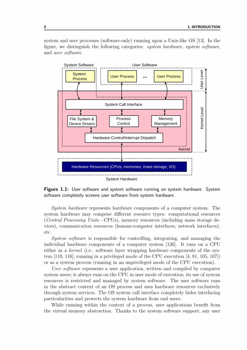
system and user processes (software-only) running upon a Unix-like OS [13]. In thefigure, we distinguish the following categories: system hardware, system software,and user software.
User ProcessSystemProcess
User Process...
Use
r Le
vel
Ker
nel L
evel
ProcessControl
System Call Interface
MemoryManagement
File System &Device Drivers
Hardware Control/Interrupt Dispatch
Kernel
User SoftwareSystem Software
Hardware Resources (CPUs, memories, mass storage, I/O)
System Hardware
Figure 1.1: User software and system software running on system hardware. Systemsoftware completely screens user software from system hardware.
System hardware represents hardware components of a computer system. Thesystem hardware may comprise different resource types: computational resources(Central Processing Units—CPUs), memory resources (including mass storage de-vices), communication resources (human-computer interfaces, network interfaces),etc.
System software is responsible for controlling, integrating, and managing theindividual hardware components of a computer system [126]. It runs on a CPUeither as a kernel (i.e., software layer wrapping hardware components of the sys-tem [110, 116], running in a privileged mode of the CPU execution [4, 81, 105, 107])or as a system process (running in an unprivileged mode of the CPU execution).
User software represents a user application, written and compiled by computersystem users; it always runs on the CPU in user mode of execution; its use of systemresources is restricted and managed by system software. The user software runsin the abstract context of an OS process and uses hardware resources exclusivelythrough system services. The OS system call interface completely hides interfacingparticularities and protects the system hardware from end users.
While running within the context of a process, user applications benefit fromthe virtual memory abstraction. Thanks to the system software support, any user

1.2. CODESIGNED APPLICATIONS IN SOFTWARE-CENTRIC SYSTEMS 3
program has an illusion of having the whole machine for itself: the process con-text comprises its own memory address space and the machine state. Whereverthe code and data physically reside, user applications see the image of the linearaddress space; there is no notion of the physical memory capacity and organisa-tion. Beside standardising the runtime environment, the OS process provides userapplications with dynamic memory management facilities, through stack and heapmechanisms [104].
The benefits of user programs using system services are multiple: (1) parallelismeven on uniprocessor systems—if a process is blocked in a system call waiting onan event, other processes can use the CPU for computation, (2) portability acrossdifferent platforms—if architecturally different computer systems support the samesystem call interface, one should be able to port simply application code just byrecompiling, (3) abstracted access to hardware—there is no need to know particu-lar characteristics of hardware devices, (4) optimised resource sharing—the systemsoftware can optimise the resource usage based on the process behaviour. Althoughthe overall performance of the system shown in Figure 1.1 is often suboptimal, thebenefits of the abstraction are overwhelming.
1.2 Codesigned Applicationsin Software-centric Systems
We call codesigned hardware and software applications the applications that havesome of their parts running on CPUs and the rest running in specialised hardware(i.e., hardware specifically designed to speed up and parallelise the execution ofperformance demanding tasks). Codesigned applications blend two models of com-putation [38]: (1) temporal computation (scarce hardware resources such as ALUs,shifters, multipliers are reused in time by the instruction sequence being executed);(2) spatial computation (where abundant hardware resources are wired and deployedin space—silicon area—to fit more closely the nature of the application, thus max-imising the processing parallelism). Standard processors (especially those intendedfor embedded applications—typically smaller and slower than cutting-edge CPUsbut more power efficient) are often extended with application-specific hardware ac-celerators [51, 58, 128] to achieve performance goals and meet power constraints.The approach becomes widely used, especially with recent developments in design-ing versatile Systems-on-Chip (SoC), the market growth of consumer appliances,and Field Programmable Gate Arrays (FPGAs) [3, 130] coming of age.
By extending the CPU with the application-specific hardware, codesigned ap-plications consist of heterogeneous code: (a) the software part consisting of CPUinstructions—typically generated by a compiler from a specification (program) writ-ten in a high-level programming language, and (b) the hardware part consisting ofhardwired logic or FPGA configuration [38, 133]—typically generated by a synthe-siser from a specification (description) written in a Hardware Description Language(HDL). Figure 1.2 shows a heterogeneous-code user program executing within thecontext of an OS process. The process executes on the CPU and, at one point
4 1. INTRODUCTION
User HWAccelerator
uninitialised data
heap
ISA code
ISA code
initialised data
stack
Execution Transferfrom SW to HW
low address
high address
?
?
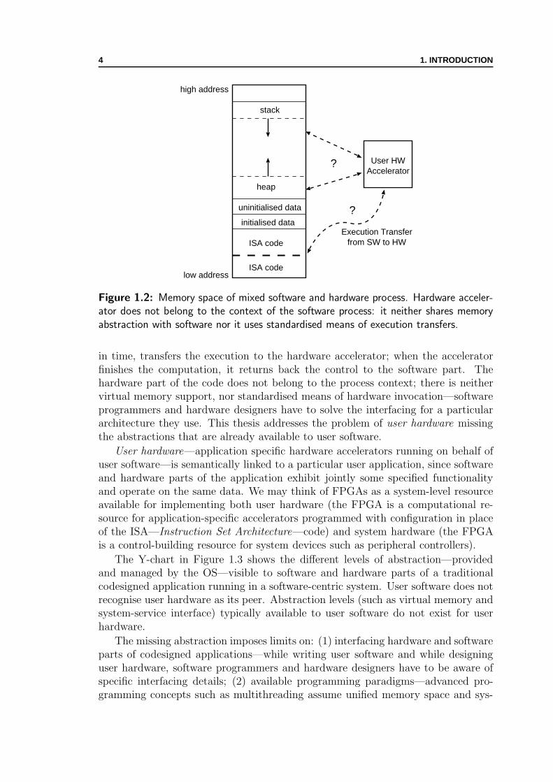
Figure 1.2: Memory space of mixed software and hardware process. Hardware acceler-ator does not belong to the context of the software process: it neither shares memoryabstraction with software nor it uses standardised means of execution transfers.
in time, transfers the execution to the hardware accelerator; when the acceleratorfinishes the computation, it returns back the control to the software part. Thehardware part of the code does not belong to the process context; there is neithervirtual memory support, nor standardised means of hardware invocation—softwareprogrammers and hardware designers have to solve the interfacing for a particulararchitecture they use. This thesis addresses the problem of user hardware missingthe abstractions that are already available to user software.
User hardware—application specific hardware accelerators running on behalf ofuser software—is semantically linked to a particular user application, since softwareand hardware parts of the application exhibit jointly some specified functionalityand operate on the same data. We may think of FPGAs as a system-level resourceavailable for implementing both user hardware (the FPGA is a computational re-source for application-specific accelerators programmed with configuration in placeof the ISA—Instruction Set Architecture—code) and system hardware (the FPGAis a control-building resource for system devices such as peripheral controllers).
The Y-chart in Figure 1.3 shows the different levels of abstraction—providedand managed by the OS—visible to software and hardware parts of a traditionalcodesigned application running in a software-centric system. User software does notrecognise user hardware as its peer. Abstraction levels (such as virtual memory andsystem-service interface) typically available to user software do not exist for userhardware.
The missing abstraction imposes limits on: (1) interfacing hardware and softwareparts of codesigned applications—while writing user software and while designinguser hardware, software programmers and hardware designers have to be aware ofspecific interfacing details; (2) available programming paradigms—advanced pro-gramming concepts such as multithreading assume unified memory space and sys-

1.3. SEAMLESS INTERFACING OF SOFTWARE AND HARDWARE 5
System HW
System SW
Memory Abstraction
User SW User HW
OS View
Partial Support
Full Support
Figure 1.3: Levels of abstraction for traditional codesigned applications in a software-centric system. User hardware misses system abstractions available to user software.
tem-enforced memory consistency; (3) portability of codesigned applications acrossdifferent platforms—it is burdensome for programmers to preserve their hardware-agnostic, high-level programming approaches, and it is challenging for hardwaredesigners to write accelerators that can run across different platforms, without anychange in the HDL code; (4) user hardware ability to use results of system services—if there is no memory abstraction present, this is either cumbersome or even im-possible (as an example, we can think of dynamic memory allocation). The thesisproposes a solution to remove the imposed limits.
1.3 Seamless Interfacing of Software and Hardware
Our goal is to provide the missing abstractions for user hardware and bring usersoftware and user hardware to the same conceptual level. We propose a unified pro-cess context for heterogeneous-code programs (consisting of user software and userhardware) to achieve transparent software and hardware interfacing and their seam-less integration. In this way, by delegating platform-specific tasks to a system-levelvirtualisation layer, we also increase the portability of codesigned applications. Thevirtualisation layer provides unified memory abstraction for software and hardwareprocesses and hides platform details from users as much as general-purpose com-puters do. It consists of an OS extension relying on a system hardware extensionthat provides (1) unified virtual memory, (2) execution transfers from software tohardware and vice versa (such that user hardware becomes able to callback softwareand use system services), and (3) multithreaded execution, for user software andhardware accelerators running within the same OS process. The presence of thevirtualisation layer brings platform-agnostic interfacing and enables (1) dynamicoptimisations of codesigned applications, and (2) unrestricted automated synthesisfrom high-level programming languages.
6 1. INTRODUCTION
System HW
System SW
Memory Abstraction
User SW User HW
OS View
Figure 1.4: User software and user hardware as peers in a proposed system supportingcodesigned applications. User hardware can run together with user software in the sameexecution context.
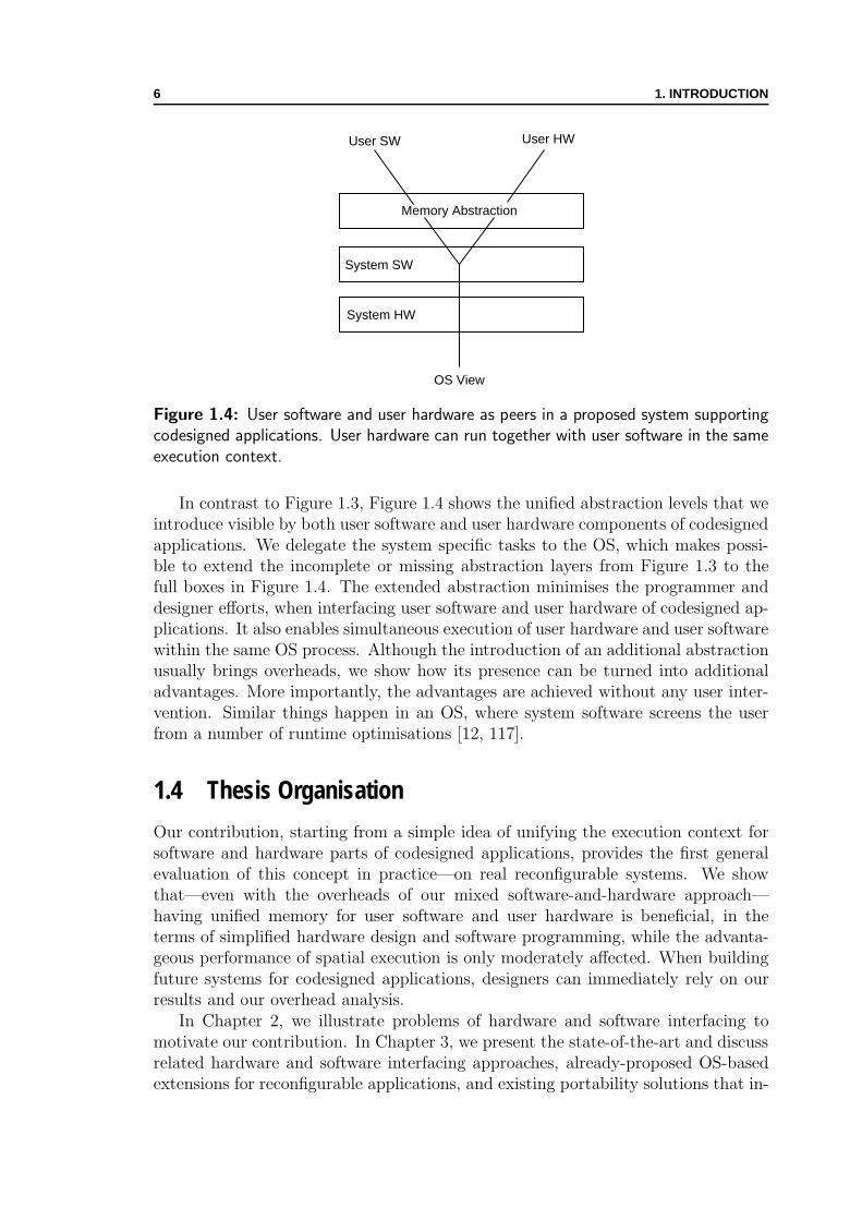
In contrast to Figure 1.3, Figure 1.4 shows the unified abstraction levels that weintroduce visible by both user software and user hardware components of codesignedapplications. We delegate the system specific tasks to the OS, which makes possi-ble to extend the incomplete or missing abstraction layers from Figure 1.3 to thefull boxes in Figure 1.4. The extended abstraction minimises the programmer anddesigner efforts, when interfacing user software and user hardware of codesigned ap-plications. It also enables simultaneous execution of user hardware and user softwarewithin the same OS process. Although the introduction of an additional abstractionusually brings overheads, we show how its presence can be turned into additionaladvantages. More importantly, the advantages are achieved without any user inter-vention. Similar things happen in an OS, where system software screens the userfrom a number of runtime optimisations [12, 117].
1.4 Thesis Organisation
Our contribution, starting from a simple idea of unifying the execution context forsoftware and hardware parts of codesigned applications, provides the first generalevaluation of this concept in practice—on real reconfigurable systems. We showthat—even with the overheads of our mixed software-and-hardware approach—having unified memory for user software and user hardware is beneficial, in theterms of simplified hardware design and software programming, while the advanta-geous performance of spatial execution is only moderately affected. When buildingfuture systems for codesigned applications, designers can immediately rely on ourresults and our overhead analysis.
In Chapter 2, we illustrate problems of hardware and software interfacing tomotivate our contribution. In Chapter 3, we present the state-of-the-art and discussrelated hardware and software interfacing approaches, already-proposed OS-basedextensions for reconfigurable applications, and existing portability solutions that in-

1.4. THESIS ORGANISATION 7
what where
unified memory Chapter 4execution transfers Chapter 6
multithreading Chapter 7
Table 1.1: Our principal contributions and the corresponding chapters.
crease platform independence for codesigned applications. In the following chapters,we discuss different aspects of our contribution.
Table 1.1 summarises our principal contributions, by showing what we add (thefirst column) to form unified OS processes for running codesigned applications andwhere we describe (the second column) the corresponding implementation. Ourcontribution (marked in Table 1.1 by the numbers of the corresponding chapters—Chapter 4, 6, and 7) provides to OS processes running codesigned applications theabstractions, services, and programming paradigms already available to software-only processes.
We show an implementation of the unified virtual memory for mixed softwareand hardware processes in Chapter 4; there, we also explain the extensions of our im-plementation that enable dynamic, runtime optimisations to improve performancetransparently to the end user—the virtual memory abstraction we propose not onlyintroduces overheads but also brings additional advantages. We introduce a perfor-mance metric for heterogeneous computing in Chapter 5; afterwards, we performexperimental measurements on reconfigurable SoC platforms to show and discussadvantages and limited overheads of our unified memory scheme. In Chapter 6, weintroduce the OS extensions supporting user hardware callbacks to user software—hardware becomes capable of invoking system calls directly; then, we show how theseextensions, together with the unified memory abstraction, enable unrestricted auto-mated synthesis of hardware accelerators from high-level programming languages.Having unified memory abstraction between software and hardware is essential forsupporting multithreaded programming paradigm. In Chapter 7, we extend thevirtualisation layer to support multithreading for codesigned applications. Finally,we conclude the thesis in Chapter 8 and give directions for future work.

8 1. INTRODUCTION

Chapter 2Missing Abstractionsfor Codesigned Applications
Wovon man nicht sprechen kann, daruber muß man schweigen.
What we cannot speak of, we must pass over in silence.—Ludwig Wittgenstein, Tractatus Logico-Philosophicus
IN this chapter, we motivate the introduction of a unified process context forrunning codesigned applications by showing hardware and software interfacing
problems in the case of typical existing architectures. The unified process abstrac-tion that we introduce releases software programmers and hardware designers frominterfacing problems. We discuss the system requirements to support this abstrac-tion.
2.1 Process Model of Computation
An OS process—in most of its implementations—provides to a user program run-ning within its context a model of computation based on the random-access ma-chine [102]—an abstract machine definition from theoretical computer science. Themodel features a CPU (with separate control and processing units) interconnectedto a random-access memory (as shown in Figure 2.1). The CPU executes a program(a sequence of instructions) and operates on data. The program and the data areall stored in the random-access memory. The computation performed by the CPUfrom Figure 2.1—in its simplest implementation—is purely temporal [38]: hard-ware resources (such as ALUs) are reused in time by the instruction sequence beingexecuted.
As Figure 2.1 shows, the process model provides a unique, virtual memoryaddress space. The architectural improvements of the physical underlying ma-chine (such as memory hierarchy, multiple issue, pipelined and out-of-order exe-cution [56]) are typically hidden from ordinary users; at most, only system soft-ware and compilers—especially in the case of VLIW machines [41]—are concerned.A memory manager component of the system software (e.g., the Virtual Memory
9

10 2. MISSING ABSTRACTIONS FOR CODESIGNED APPLICATIONS
Virtual Memory
ControlUnit
ProcessingUnit
Register File
ALU
CPU
Memory
Processing
Control
Figure 2.1: Process model of computation: a stored-program computer. The controlunit fetches and executes the program stored in the random access memory. The programoperates on data also stored in the same memory.
Manager—VMM—of the OS) provides the virtual memory abstraction, no matterwhat is the organisation of the underlying physical memory.
Figure 2.2 depicts the temporal computation machine from Figure 2.1 extendedwith a spatial computation engine—an application-specific hardware accelerator. Incontrast to the CPU from Figure 2.1, we can notice the following differences: (1)the hardware accelerator employs custom processing units (Data-Flow processingUnits—DFUs) deployed in space and tailored to fit as much as possible a specificapplication data-flow; (2) there is no centralised register file in the hardware ac-celerator but the data local to the computation are stored in distributed registerscorresponding to the data-flow; (3) the number and the size of memory ports arecustom to the application; (4) there is no centralised control, it is rather distributedacross the accelerator; (5) the configuration (in the case of reconfigurable hardwareaccelerators) or hardwired logic gates (in the case of ASIC hardware accelerators)determine the behaviour of the accelerator, not the sequence of programming in-structions.
DataMemory
HW Accelerator
ConfigurationUnit
Virtual Memory(Program and Data)
ControlUnit
RegisterFile
ALU
CPU
ConfigurationMemory?
?
...
...DataMemory
DataMemory
Custom Data Memory
Memory Processing Control DFU Data Flow processing Unit CU Control (or Configuration) Unit
Registers Registers Registers
CU CU
Registers Registers
CU
DFU DFU DFU
DFU DFU
Figure 2.2: Blending temporal and spatial ways of computation. The hardware accel-erator performs application-specific computation. There is no common address spacebetween software and hardware. Furthermore, there is no standardised way of executiontransfers.

2.2. TYPICAL ARCHITECTURES: ACCESSING MEMORY 11
Although the machine from Figure 2.2 may run a given application faster thanthe temporal machine from Figure 2.1, we notice that the virtual memory abstrac-tion and the neat programming environment have disappeared: (1) user softwareand user hardware do not share the memory address space—it is typically on theapplication programmer to arrange the communication and data transfers; (2) thereis no standardised way of execution transfer—it is again on the application pro-grammer to explicitly control the hardware accelerator; (3) system services are onlypartially available to user hardware—programmers may use software wrappers tocall system services on behalf of the user hardware. In the following sections, weillustrate the software programming and hardware design issues for typical existingarchitectures running codesigned applications [17, 72, 112].
2.2 Typical Architectures: Accessing Memory
Having disjoint memory address spaces for user software and user hardware exposesdata communication to users; it is the task of software programmers and hardwaredesigners to arrange memory transfers from software to hardware address spaces andvice versa. In this section, we show typical arrangements for hardware acceleratoraccesses to the memory.
CPU
MMU
Cache
System Bus
MainMemory
LocalMemory
HardwareAccelerator
Slave
Master
FPGA or ASIC
WorkingMemory
Figure 2.3: Typical hardware accelerator accessing local memory. While user softwarehas an ideal image of the memory provided by virtual memory mechanisms, user hardwaregenerates physical addresses of the local memory. It is the task of the programmer toarrange the communication between user software and user hardware.
Figure 2.3 shows a possible implementation of the machine from Figure 2.2: thehardware accelerator (user hardware) directly accesses a local on-chip memory toperform the computation. The user software, running on the CPU, has a perfect,linear image of the memory provided by the virtual memory manager of the OS [116].For speeding up the execution, a system hardware unit called Memory ManagementUnit (MMU), and often integrated within the CPU [56] supports the translation of
12 2. MISSING ABSTRACTIONS FOR CODESIGNED APPLICATIONS
virtual memory addresses. In contrast to the user software, the user hardware isdirectly interfaced to the system hardware and generates physical memory addressesfor fast accesses to the local memory. The programmer controls the accelerator andaccesses its local memory through a memory mapped region (this assumes using themmap system call of the OS).
/* Software-only version */
idea block A[n64], B[n64];
...
idea cipher sw (A, B, n64);
...
/* HW accelerator version accessing local memory */
idea block *buff =
mmap(0, sizeof(idea block), LMEM PHYADDR);
...
data chunk = LMEM SIZE / 2; data ptr = 0;
while (data ptr < n64 * sizeof(idea block)) {memcpy (buf, A + data ptr, data chunk);
IDEA CTRL REG = START;
while(*IDEA STATUS REG != FINISH);
IDEA STATUS REG = INIT;
memcpy (B + data pt, buf + data chunk, data chunk);
data ptr += data chunk;
}...
(a) (b)
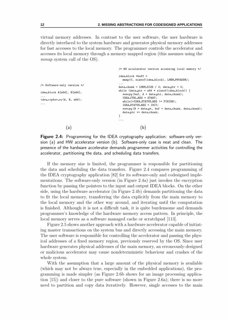
Figure 2.4: Programming for the IDEA cryptography application: software-only ver-sion (a) and HW accelerator version (b). Software-only case is neat and clean. Thepresence of the hardware accelerator demands programmer activities for controlling theaccelerator, partitioning the data, and scheduling data transfers.
If the memory size is limited, the programmer is responsible for partitioningthe data and scheduling the data transfers. Figure 2.4 compares programming ofthe IDEA cryptography application [82] for its software-only and codesigned imple-mentations. The software-only version (in Figure 2.4a) just invokes the encryptionfunction by passing the pointers to the input and output IDEA blocks. On the otherside, using the hardware accelerator (in Figure 2.4b) demands partitioning the datato fit the local memory, transferring the data explicitly from the main memory tothe local memory and the other way around, and iterating until the computationis finished. Although it is not a difficult task, it is quite burdensome and demandsprogrammer’s knowledge of the hardware memory access pattern. In principle, thelocal memory serves as a software managed cache or scratchpad [113].
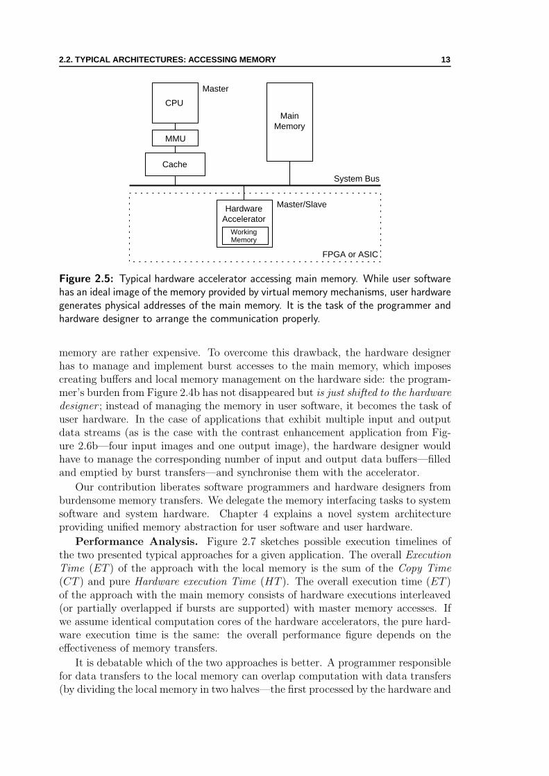
Figure 2.5 shows another approach with a hardware accelerator capable of initiat-ing master transactions on the system bus and directly accessing the main memory.The user software is responsible for controlling the accelerator and passing the phys-ical addresses of a fixed memory region, previously reserved by the OS. Since userhardware generates physical addresses of the main memory, an erroneously-designedor malicious accelerator may cause nondeterministic behaviour and crashes of thewhole system.
With the assumption that a large amount of the physical memory is available(which may not be always true, especially in the embedded applications), the pro-gramming is made simpler (as Figure 2.6b shows for an image processing applica-tion [15]) and closer to the pure software (shown in Figure 2.6a); there is no moreneed to partition and copy data iteratively. However, single accesses to the main
2.2. TYPICAL ARCHITECTURES: ACCESSING MEMORY 13
CPU
MMU
Cache
System Bus
MainMemory
HardwareAccelerator
Master/Slave
Master
FPGA or ASIC
WorkingMemory
Figure 2.5: Typical hardware accelerator accessing main memory. While user softwarehas an ideal image of the memory provided by virtual memory mechanisms, user hardwaregenerates physical addresses of the main memory. It is the task of the programmer andhardware designer to arrange the communication properly.
memory are rather expensive. To overcome this drawback, the hardware designerhas to manage and implement burst accesses to the main memory, which imposescreating buffers and local memory management on the hardware side: the program-mer’s burden from Figure 2.4b has not disappeared but is just shifted to the hardwaredesigner ; instead of managing the memory in user software, it becomes the task ofuser hardware. In the case of applications that exhibit multiple input and outputdata streams (as is the case with the contrast enhancement application from Fig-ure 2.6b—four input images and one output image), the hardware designer wouldhave to manage the corresponding number of input and output data buffers—filledand emptied by burst transfers—and synchronise them with the accelerator.
Our contribution liberates software programmers and hardware designers fromburdensome memory transfers. We delegate the memory interfacing tasks to systemsoftware and system hardware. Chapter 4 explains a novel system architectureproviding unified memory abstraction for user software and user hardware.
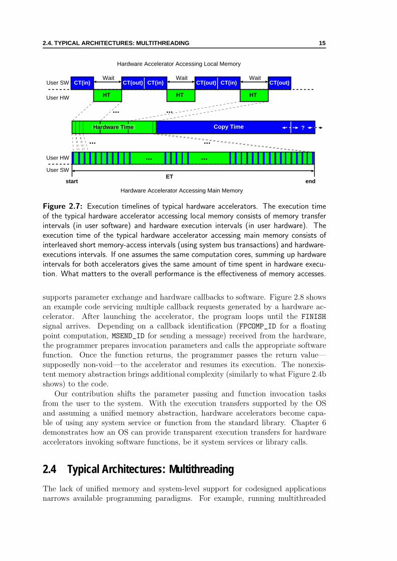
Performance Analysis. Figure 2.7 sketches possible execution timelines ofthe two presented typical approaches for a given application. The overall ExecutionTime (ET ) of the approach with the local memory is the sum of the Copy Time(CT ) and pure Hardware execution Time (HT ). The overall execution time (ET )of the approach with the main memory consists of hardware executions interleaved(or partially overlapped if bursts are supported) with master memory accesses. Ifwe assume identical computation cores of the hardware accelerators, the pure hard-ware execution time is the same: the overall performance figure depends on theeffectiveness of memory transfers.
It is debatable which of the two approaches is better. A programmer responsiblefor data transfers to the local memory can overlap computation with data transfers(by dividing the local memory in two halves—the first processed by the hardware and

14 2. MISSING ABSTRACTIONS FOR CODESIGNED APPLICATIONS
/* Software-only version */
unsigned char outimg[imgsize],
inpimg[4][imgsize];
...
contrast enhancement sw
(outimg, inpimg, winsize, imgsize);
...
/* HW accelerator version
accessing main memory */
unsigned char *resimg =
mmap(0, imgsize, RES PHYADDR);
unsigned char *inpimg[i] =
mmap(0, winsize,INPi PHYADDR);
...
memcpy (inpimg[i], cam out[frame i], winsize);
CONTRAST CTRL REG = START;
while(*CONTRAST STATUS REG != FINISH);
CONTRAST STATUS REG = INIT;
memcpy (outimg, resimg, winsize);
...
(a) (b)
Figure 2.6: Programming for the contrast enhancement application: software-onlyversion (a) and HW accelerator version (b). Software-only case is neat and clean.The presence of the hardware accelerator demands controlling the accelerator and usingmmap() system call.
the second used for copying) or use a DMA (although this would mean descendingfrom the user-level to system programming) to speed up the process. A hardwaredesigner responsible for memory accesses to the main memory can use burst accessesand hardware-managed buffers to improve the performance. Whichever of the twoapproaches an application architect chooses, the memory management tasks, whichare normally delegated to the system, burden the user-level software and hardware:pushing the management of the memory hierarchy from the programmer toward thevirtual memory manager and the cache controller is the analogous assignment ofthe general computer architecture.
2.3 Typical Architectures: Callbacks to Software
There are some cases in which hardware accelerators may want to call back software.For example, hardware may request software to invoke a system call, service anexception, demand an external computation, display the accelerator status, or senda message to some other application part (Chapter 6 shows callbacks to softwarerequired for mapping high-level languages to hardware).
Programmers and designers wanting to support hardware callbacks to softwareencounter two principal difficulties: (1) writing additional code to service callbacksis necessary, and (2) parameter passing conventions are not standardised but ratherchosen in an ad-hoc manner. The additional obstacle is the lack of the unifiedmemory between software and hardware: if there is no memory abstraction present,some software return values can be completely useless to hardware (we can takemalloc() function as an example).
While the runtime environment implements a calling sequence—the sequence ofinstructions and data arrangements necessary to perform a function call [2]—forsoftware-only applications (usually through stack management), no such arrange-ment exists for codesigned applications; the programmer has to write the code that
2.4. TYPICAL ARCHITECTURES: MULTITHREADING 15
HT
WaitUser SW
User HW
start
Hardware Accelerator Accessing Local Memory
Hardware Accelerator Accessing Main Memory
CT(out)CT(in) CT(in)
User HW ... ...
User SW
end
...
...
...
...
?
HT
WaitCT(out) CT(in)
HT
WaitCT(out)
ET
Hardware Time Copy Time
Figure 2.7: Execution timelines of typical hardware accelerators. The execution timeof the typical hardware accelerator accessing local memory consists of memory transferintervals (in user software) and hardware execution intervals (in user hardware). Theexecution time of the typical hardware accelerator accessing main memory consists ofinterleaved short memory-access intervals (using system bus transactions) and hardware-executions intervals. If one assumes the same computation cores, summing up hardwareintervals for both accelerators gives the same amount of time spent in hardware execu-tion. What matters to the overall performance is the effectiveness of memory accesses.
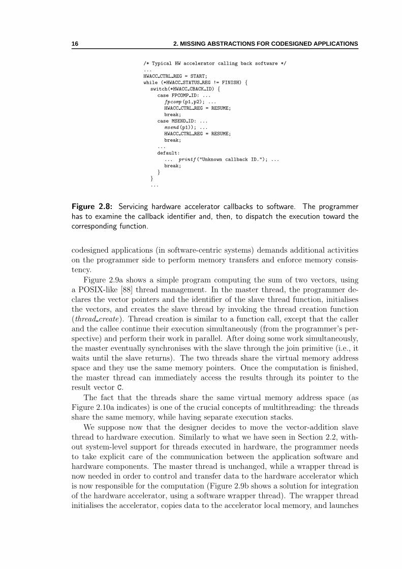
supports parameter exchange and hardware callbacks to software. Figure 2.8 showsan example code servicing multiple callback requests generated by a hardware ac-celerator. After launching the accelerator, the program loops until the FINISH
signal arrives. Depending on a callback identification (FPCOMP_ID for a floatingpoint computation, MSEND_ID for sending a message) received from the hardware,the programmer prepares invocation parameters and calls the appropriate softwarefunction. Once the function returns, the programmer passes the return value—supposedly non-void—to the accelerator and resumes its execution. The nonexis-tent memory abstraction brings additional complexity (similarly to what Figure 2.4bshows) to the code.
Our contribution shifts the parameter passing and function invocation tasksfrom the user to the system. With the execution transfers supported by the OSand assuming a unified memory abstraction, hardware accelerators become capa-ble of using any system service or function from the standard library. Chapter 6demonstrates how an OS can provide transparent execution transfers for hardwareaccelerators invoking software functions, be it system services or library calls.
2.4 Typical Architectures: Multithreading
The lack of unified memory and system-level support for codesigned applicationsnarrows available programming paradigms. For example, running multithreaded
16 2. MISSING ABSTRACTIONS FOR CODESIGNED APPLICATIONS
/* Typical HW accelerator calling back software */
...
HWACC CTRL REG = START;
while (*HWACC STATUS REG != FINISH) {switch(*HWACC CBACK ID) {
case FPCOMP ID: ...
fpcomp (p1,p2); ...
HWACC CTRL REG = RESUME;
break;
case MSEND ID: ...
msend (p1)); ...
HWACC CTRL REG = RESUME;
break;
...
default:
... printf ("Unknown callback ID."); ...
break;
}}...
Figure 2.8: Servicing hardware accelerator callbacks to software. The programmerhas to examine the callback identifier and, then, to dispatch the execution toward thecorresponding function.
codesigned applications (in software-centric systems) demands additional activitieson the programmer side to perform memory transfers and enforce memory consis-tency.
Figure 2.9a shows a simple program computing the sum of two vectors, usinga POSIX-like [88] thread management. In the master thread, the programmer de-clares the vector pointers and the identifier of the slave thread function, initialisesthe vectors, and creates the slave thread by invoking the thread creation function(thread create). Thread creation is similar to a function call, except that the callerand the callee continue their execution simultaneously (from the programmer’s per-spective) and perform their work in parallel. After doing some work simultaneously,the master eventually synchronises with the slave through the join primitive (i.e., itwaits until the slave returns). The two threads share the virtual memory addressspace and they use the same memory pointers. Once the computation is finished,the master thread can immediately access the results through its pointer to theresult vector C.
The fact that the threads share the same virtual memory address space (asFigure 2.10a indicates) is one of the crucial concepts of multithreading: the threadsshare the same memory, while having separate execution stacks.
We suppose now that the designer decides to move the vector-addition slavethread to hardware execution. Similarly to what we have seen in Section 2.2, with-out system-level support for threads executed in hardware, the programmer needsto take explicit care of the communication between the application software andhardware components. The master thread is unchanged, while a wrapper thread isnow needed in order to control and transfer data to the hardware accelerator whichis now responsible for the computation (Figure 2.9b shows a solution for integrationof the hardware accelerator, using a software wrapper thread). The wrapper threadinitialises the accelerator, copies data to the accelerator local memory, and launches

2.4. TYPICAL ARCHITECTURES: MULTITHREADING 17
/* Master Thread */
void main () {int *A, *B, *C;
int n;
int thr id;
...
read (A, n);
read (B, n);
thr id = thread create
(add vect, A, B, C, n);
do some work meanwhile();
thread join (thr id);
...
}
/* Slave Thread */
void add vect (int *A, int *B, int *C, int n) {int i;
for(i = 0; i < n; i++)
C[i] = A[i] + B[i];
}}
/* Master Thread */
void main () {int *A, *B, *C;
int n;
int thr id;
...
read (A, n);
read (B, n);
thr id = thread create(add vectors, A, B, C, n);
do some work meanwhile();
thread join (thr id);
...
}
/* Wrapper Thread */
void add vect (int *A, int *B, int *C, int n) {int d chunk = BUF SIZE / 3;
int *d ptr = 0;
/* initialise accelerator */
write(HWACC CTRL, INIT);
while (d ptr < n) {copy (A + d ptr, BUF BASE, d chunk);
copy (B + d ptr, BUF BASE + d chunk, d chunk);
/* launch accelerator */
write (HWACC CTRL, ADD VECT);
while () {if (read(HWACC STATUS) == FINISHED) {
copy (BUF BASE + 2*d chunk,
C + d ptr, d chunk);
break;
} else {do some work meanwhile();
}}d ptr += d chunk;
} ...
}
(a) (b)
Figure 2.9: Multithreaded code for software-only (a) and hardware accelerator version(b) of codesigned application. In the software-only case, the threads use the samememory pointers. In the codesigned case, the programmer has to write a wrapper.
the computation. Since the input data does not necessarily fit to the local memoryof the accelerator, the wrapper iteratively copies data back and forth, until all thedata are processed. The hardware accelerator and the software threads do not sharethe same memory address space (as Figure 2.10b shows).
For a codesigned application with multiple threads in hardware, the programmerhas to create a wrapper thread per hardware accelerator. Changing the HDL codeof a hardware accelerator and its memory access pattern may require changes in thewrapper thread—the interfacing details burden software programmers and hardwaredesigners.
Our contribution enables wrapper-free and access-pattern-independent multi-threaded execution of user software and user hardware. Chapter 7 presents thesystem-level extensions to enforce memory consistency and support synchronisation,thus enabling multithreaded programming paradigm for codesigned applications.
18 2. MISSING ABSTRACTIONS FOR CODESIGNED APPLICATIONS
SW
Virtual Memory
SWcreate
join
MasterThread
SlaveThread
A B C SIZE
HW
Local Memory
SW
Virtual Memory
SWcreate
join
MasterThread
WrapperThread Accelerator
CA B BUF_SIZESIZE
BUF_BASE
(a) (b)
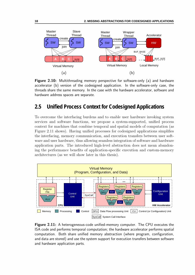
Figure 2.10: Multithreading memory perspective for software-only (a) and hardwareaccelerator (b) version of the codesigned application. In the software-only case, thethreads share the same memory. In the case with the hardware accelerator, software andhardware address spaces are separate.
2.5 Unified Process Context for Codesigned Applications
To overcome the interfacing burdens and to enable user hardware invoking systemservices and software functions, we propose a system-supported, unified processcontext for machines that combine temporal and spatial models of computation (asFigure 2.11 shows). Having unified processes for codesigned applications simplifiesthe interfacing, memory communication, and execution transfers between user soft-ware and user hardware, thus allowing seamless integration of software and hardwareapplication parts. The introduced high-level abstraction does not mean abandon-ing the performance benefits of application-specific execution and custom-memoryarchitectures (as we will show later in this thesis).
HW Accelerator
Virtual Memory(Program, Configuration, and Data)
SysCall
...
Memory Processing Control DFU Data Flow processing Unit CU Control (or Configuration) Unit
ConfigurationUnit
SysCall System Call Interface
Registers Registers Registers
CU CU
Registers Registers
CU
DFU DFU DFU
DFU DFU
ControlUnit
RegisterFile
ALU
CPU
Figure 2.11: A heterogeneous-code unified-memory computer. The CPU executes theISA code and performs temporal computation; the hardware accelerator performs spatialcomputation. Both share unified memory abstraction (where program, configuration,and data are stored) and use the system support for execution transfers between softwareand hardware application parts.
2.5. UNIFIED PROCESS CONTEXT FOR CODESIGNED APPLICATIONS 19
We propose making hardware accelerators capable of (1) accessing virtual mem-ory and sharing the address space with software to enable transparent memorycommunication and screen user software and user hardware from the interfacingdetails, and (2) implementing a common calling sequence with software to supporttransparent execution transfers and user hardware callbacks to user software.
CPU
MMU
Cache
System Bus
MainMemory
Slave orMaster/Slave
Master
FPGA or ASIC
WMU
Local Memory
HardwareAccelerator
WorkingMemory
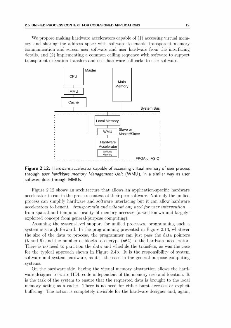
Figure 2.12: Hardware accelerator capable of accessing virtual memory of user processthrough user hardWare memory Management Unit (WMU), in a similar way as usersoftware does through MMUs.
Figure 2.12 shows an architecture that allows an application-specific hardwareaccelerator to run in the process context of their peer software. Not only the unifiedprocess can simplify hardware and software interfacing but it can allow hardwareaccelerators to benefit—transparently and without any need for user intervention—from spatial and temporal locality of memory accesses (a well-known and largely-exploited concept from general-purpose computing).
Assuming the system-level support for unified processes, programming such asystem is straightforward. In the programming presented in Figure 2.13, whateverthe size of the data to process, the programmer can just pass the data pointers(A and B) and the number of blocks to encrypt (n64) to the hardware accelerator.There is no need to partition the data and schedule the transfers, as was the casefor the typical approach shown in Figure 2.4b. It is the responsibility of systemsoftware and system hardware, as it is the case in the general-purpose computingsystems.
On the hardware side, having the virtual memory abstraction allows the hard-ware designer to write HDL code independent of the memory size and location. Itis the task of the system to ensure that the requested data is brought to the localmemory acting as a cache. There is no need for either burst accesses or explicitbuffering. The action is completely invisible for the hardware designer and, again,

20 2. MISSING ABSTRACTIONS FOR CODESIGNED APPLICATIONS
/* Virtual memory-enabled hardware version */
idea block A[n64], B[n64];
...
idea cipher hw (A, B, n64);
...
Figure 2.13: Programming for the IDEA cryptography application with a virtual-memory-enabled hardware accelerator. The accelerator is capable of accessing the datato process through the virtual memory pointers to the user address space.
it is on the system to perform it transparently. In a similar manner, the memoryhierarchy in general-purpose systems is managed transparently to the end user (e.g.,cache block transfers and virtual address translations).
Figure 2.14 compares excerpts of a VHDL-like code for both the typical andthe virtual-memory-enabled IDEA hardware accelerators. While writing the codefor the typical hardware accelerator, the hardware designer has to (1) use physicaladdresses of the local memory, (2) be aware of the memory size, and (3) arrangethe memory partitioning in accordance with the programmer. The code is inher-ently platform dependent. While writing the code for the virtual-memory-enabledhardware accelerator, the hardware designer does not care about these tasks. Theaccelerator generates virtual memory addresses and the system provides translationand synchronisation: the user code becomes portable.
-- Initialisation
-- with platform-dependent addresses
ptr a <= LMEM BASE;
ptr b <= LMEM BASE + LMEM SIZE/2;
-- Computation
cycle 1:
-- partition of A[]
LMEM PHYADDR <= ptr a;
LMEM ACCESS <= ’1’;
LMEM WR <= ’0’;
cycle 2:
reg a <= DATAIN;
cycle 3:
reg b := IDEA (reg a);
-- an element in a partition of B[]
LMEM PHYADDR <= ptr b;
DATAOUT <= reg b;
LMEM ACCESS <= ’1’;
LMEM WR <= ’1’;
ptr {a,b} <= ptr {a,b} + 1;
if (ptr b = LMEM BASE + LMEM SIZE) then
-- finished for a data chunk
partial finish ;
else
cycle 1 ;
end if;
-- Initialisation with runtime-dependent
-- virtual memory pointers
ptr a <= A;
ptr b <= B;
i := 0;
-- Computation
cycle 1:
-- object A[]
VMEM VIRTADDR <= ptr a;
VMEM ACCESS <= ’1’;
VMEM WR <= ’0’;
cycle 2:
reg a <= DATAIN;
cycle 3:
reg b := IDEA (reg a);
-- any element in B[]
VMEM VIRTADDR <= ptr b;
DATAOUT <= reg b;
VMEM ACCESS <= ’1’;
VMEM WR <= ’1’;
ptr {a,b},i <= ptr {a,b},i + 1;
if (i = n64) then
-- finished for the entire vectors
finish ;
else
cycle 1 ;
end if;
(a) (b)
Figure 2.14: Platform-dependent (a) and portable (b) VHDL-like code of the hardwareaccelerator. The platform dependent code reflects the limited size of the local memoryand uses physical memory addresses. The portable code uses virtual memory addresseswith no notion where the data actually reside.

2.5. UNIFIED PROCESS CONTEXT FOR CODESIGNED APPLICATIONS 21
System Requirements. To achieve our goal of having unified process contextfor codesigned applications, we need (1) system hardware support for user hardwareinvocation, virtual address translation, and memory coherence enforcement, and (2)system software support for steering these activities and enabling the interopera-tion with user software. In general-purpose computer systems, memory managementunits (MMUs) and cache controllers [33, 56] represent the system hardware respon-sible for virtual address translation and transparent and coherent memory hierarchy.The OS kernel, in turn, represents the system software responsible for managing thehardware and for providing the process model of computation to user software. It isthe responsibility of system designers to decide how to partition—between systemsoftware and system hardware—the task of providing the process and memory ab-stractions. Researchers have explored different approaches [95], many of them beingdemonstrated in practice [1, 16, 74].
We choose a mixed software and hardware scheme that employs (1) a hardwaretranslation engine (the user hardWare memory Management Unit—WMU—fromFigure 2.12) and (2) an OS extension. The scheme slightly trades off performancefor applicability to a wide range of reconfigurable SoCs; there are no hardwarerequirements regarding the system-bus capability to support memory coherence.Our approach is not limited to reconfigurable SoCs, although we primarily targetthese devices in our case studies. Following the state-of-the-art (in Chapter 3),we present details of our architecture, and demonstrate its prevailing benefits andlimited drawbacks in Chapters 4, 5, 6, and 7. We also show that performance is notsignificantly affected, despite the inherent overhead of our scheme.

22 2. MISSING ABSTRACTIONS FOR CODESIGNED APPLICATIONS

Chapter 3State of the Art
Grace a l’art, au lieu de voir un seul monde, le notre, nous le voyons se multiplier etautant qu’il y a d’artistes originaux, autant nous avons de mondes a notredisposition, plus differents les uns des autres que ceux qui roulent dans l’infini, etbien des siecles apres qu’est eteint le foyer dont il emanait, qu’il s’appelatRembrandt ou Ver Meer, nous envoient encore leur rayon special.
—Marcel Proust, Le Temps Retrouve
BOTH research and industry have tackled a large number of issues from hardwareand software codesign, bus wrappers and memory subsystems for embedded
computing, programming paradigms and OS-support for reconfigurable computing,and general hardware and software interfacing. In this chapter, we present thestate-of-the-art and distinguish our contribution from related works.
We first show in Section 3.1 how our research relates to industry standardisationefforts for providing IP-level design reuse and portability, and to research on memorywrappers and memory subsystems for embedded computing. Then, in Section 3.2,we compare our work to major approaches of reconfigurable computing for extendingstandard CPUs with application-specific hardware accelerators. In the same sectionwe also discuss related work on parallel programming paradigms for reconfigurablecomputing, and we present the status of the research on OSs for reconfigurablecomputing. In Section 3.3, we show existing approaches also offering portable andseamless interfacing between software and hardware. Section 3.4 presents relatedwork that motivated our user-transparent dynamic optimisation technique. Finally,Section 3.5 compares existing work on high-level synthesis with our unrestrictedautomated approach.
3.1 Memory Wrappers and Subsystems
The increasing need for IP-reuse and component-based system design motivatesabundant industrial and research activities regarding memory abstractions and com-munication interfaces. On the industry side, many standardisation efforts have fa-cilitated interconnecting IP blocks that come from different sources. For example,AMBA [8] and CoreConnect [59] are some well-known industry standards for on-chip bus interconnections. Going one step further, the Virtual Component Interface
23

24 3. STATE OF THE ART
(VCI) is a standard [71] that separates bus-specific interfacing logic from the internalfunctionality of IP blocks; in this way, it hides the details of the underlying bus in-terface from the IP designer. On the research side, many researchers have addressedmemory wrappers and transparent bus interconnections. For example, Lyonnard etal. [78] and Gharsalli et al. [49] propose automatic generation of application-specificinterfaces and memory wrappers for IP designs. Similarly, Lee and Bergmann [69]introduce an interfacing layer that automates connecting IP designs to a wide va-riety of interface architectures. The main originality of our idea, with respect tothe standardisation efforts and wrapper-related works, is not in the abstraction ofthe memory interface details (signals, protocols, etc.) between generic producersand consumers, but in the dynamic allocation of the interfacing memory, buffer, orcommunication ports between a processor and a hardware accelerator—that is theimplication of the OS in the process.
Extensive literature exists on the design and allocation of application-specificmemory systems, typically for ASIC end SoC designs (e.g., Catthoor et al. [28]discuss methodologies for custom memory management, while Panda, Dutt, andNicolau [91] survey different memory issues for SoCs). In most cases, the existingapproaches are compiler-based static techniques consisting of (1) design methodolo-gies for customising the ASIC memory hierarchy for specific applications and (2)software transformations to exploit better a given memory hierarchy. The lattertechniques are independent from the actual interface we handle, and their proficientuse can enhance the design of hardware accelerators, including virtual-memory-enabled ones. In contrast to well-established static techniques, a few works havea dynamic flavour. For example, the work of Leeman et al. [70] on refining dy-namic memory management for embedded systems is fully complementary to ourapproach. Since our system layer—providing the unified memory for software andhardware—is dynamic in its nature, one could consider using Leeman’s methodologyto improve the dynamic behaviour of our memory allocation process.
In the area of memory systems for reconfigurable computing, Herz et al. [57]have studied the generation of optimal access patterns for coprocessors within SoCarchitectures; their focus is not in abstraction from architectural details and porta-bility, as it is the case in this thesis. Although we only use simple access patterns forvalidation, hardware designers can use any access pattern in conjunction with theunified memory. In this way, their address generation techniques are complementaryto our work.
3.2 Reconfigurable Computing
In this section, we first relate our architecture with two major architectural ap-proaches in reconfigurable computing that blend temporal and spatial computation.Then, we compare our approach to parallel execution in reconfigurable SoCs withrecent developments in multithreading for reconfigurable applications. Finally, wesurvey existing OS extensions—complementary to ours—that address system soft-ware support for reconfigurable applications.

3.2. RECONFIGURABLE COMPUTING 25
Register File
ALU MUL LD/ST
Data Memory
Spe
cial
ised
CP
U
out1 = F(in1, in2, in3, in4, in5)out2 = G(in1, in2, in3, in4, in5)out3 = H(in1, in2, in3, in4, in5)
RFU
Figure 3.1: Specialised CPU extended with Reconfigurable Functional Unit (RFU).The RFU implements a special instruction built by collapsing multiple ISA instructionsinto the complex one.
3.2.1 Reconfigurable Accelerator Integration
Two of the most common approaches that mix temporal computation within a CPUand spatial computation within reconfigurable hardware are: (1) fine-grained, spe-cialising the CPU data-path with an application-specific reconfigurable functionalunit (RFU in Figure 3.1); and (2) coarse-grained, specialising the application exe-cution off the CPU, with an application-specific reconfigurable accelerator (actinglike a coprocessor in Figure 3.2).
Past research has demonstrated the feasibility of extending a CPU data-pathwith a reconfigurable functional unit (e.g., [10, 98, 132]). The approach is alsowell-known and studied in the ASIC world [58]. Such extensions demand creatingnew ISA instructions for the given CPU. Apart from the need for automation whencreating the new instructions, using the extensions effectively requires some compilermodifications (as, for example, Ye et al. [132] demonstrate). Our research does notaddress this approach, as we rather target reconfigurable SoCs with nonextensibleCPU cores.
Closer to our concerns are systems adopting the coarse-grained approach—withhardware accelerators acting like coprocessors. We have shown in Section 2.5 ourtarget model of computation mixing temporal and spatial computation. Other re-searchers have also considered using hardware accelerators acting like coprocessors(e.g., Hauser and Wawrzynek [55] propose GARP—a MIPS processor with a re-configurable coprocessor; Budiu et al. [23] introduce ASH—a coprocessor-based im-plementation of spatial computation; Vassiliadis et al. [118] present MOLEN—apolymorphic processor incorporating general-purpose and custom computing). Incontrast to our work, system-level management of memory hierarchy is out of theirconcerns. For example, Budiu et al. [23] put aside maintaining a coherent view ofmemory and the OS integration, and rather investigate compilation and synthesisissues. Callahan, Hauser, and Wawrzynek [25], like Vassiliadis et al. [118], mostlyrely on resolving the interfacing through compiler technology. In contrast, we solvethe interfacing at the system level—no need for compiler customisation—by provid-ing to user hardware the same abstractions that user software already has. None of
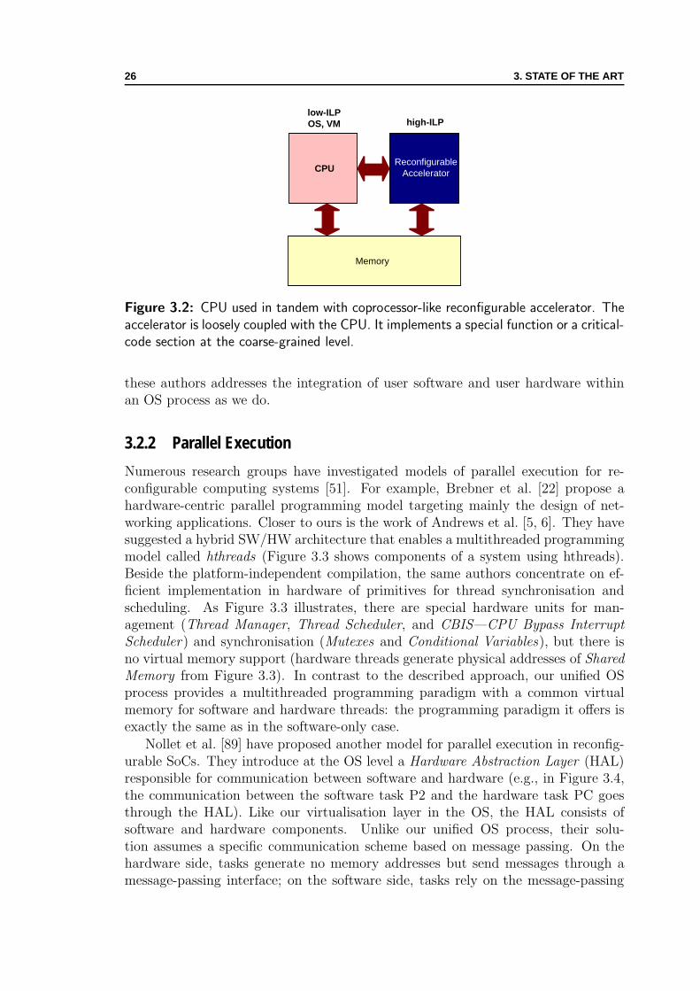
26 3. STATE OF THE ART
Memory
ReconfigurableAcceleratorCPU
high-ILPlow-ILPOS, VM
Figure 3.2: CPU used in tandem with coprocessor-like reconfigurable accelerator. Theaccelerator is loosely coupled with the CPU. It implements a special function or a critical-code section at the coarse-grained level.
these authors addresses the integration of user software and user hardware withinan OS process as we do.
3.2.2 Parallel Execution
Numerous research groups have investigated models of parallel execution for re-configurable computing systems [51]. For example, Brebner et al. [22] propose ahardware-centric parallel programming model targeting mainly the design of net-working applications. Closer to ours is the work of Andrews et al. [5, 6]. They havesuggested a hybrid SW/HW architecture that enables a multithreaded programmingmodel called hthreads (Figure 3.3 shows components of a system using hthreads).Beside the platform-independent compilation, the same authors concentrate on ef-ficient implementation in hardware of primitives for thread synchronisation andscheduling. As Figure 3.3 illustrates, there are special hardware units for man-agement (Thread Manager, Thread Scheduler, and CBIS—CPU Bypass InterruptScheduler) and synchronisation (Mutexes and Conditional Variables), but there isno virtual memory support (hardware threads generate physical addresses of SharedMemory from Figure 3.3). In contrast to the described approach, our unified OSprocess provides a multithreaded programming paradigm with a common virtualmemory for software and hardware threads: the programming paradigm it offers isexactly the same as in the software-only case.
Nollet et al. [89] have proposed another model for parallel execution in reconfig-urable SoCs. They introduce at the OS level a Hardware Abstraction Layer (HAL)responsible for communication between software and hardware (e.g., in Figure 3.4,the communication between the software task P2 and the hardware task PC goesthrough the HAL). Like our virtualisation layer in the OS, the HAL consists ofsoftware and hardware components. Unlike our unified OS process, their solu-tion assumes a specific communication scheme based on message passing. On thehardware side, tasks generate no memory addresses but send messages through amessage-passing interface; on the software side, tasks rely on the message-passing
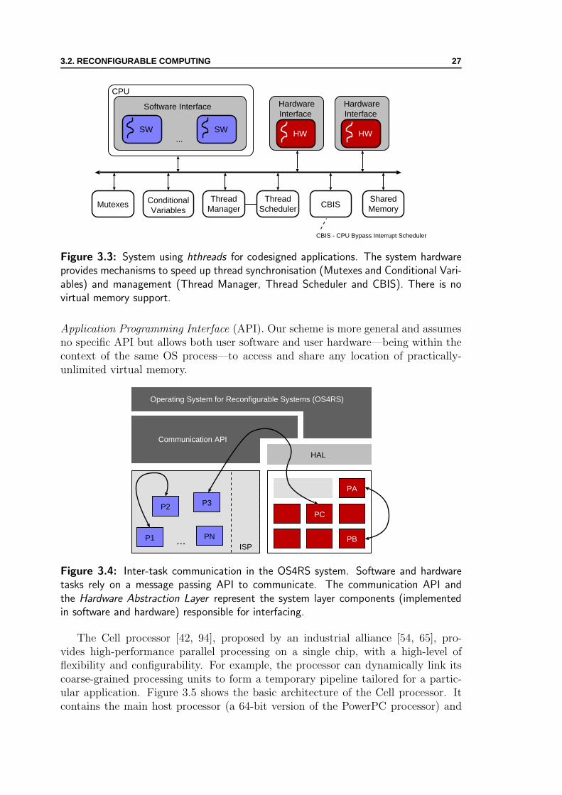
3.2. RECONFIGURABLE COMPUTING 27
SW SW...
Software Interface
CPU
HW
HardwareInterface
HWHW
HardwareInterface
HW
Mutexes ConditionalVariables
ThreadManager
ThreadScheduler CBIS
SharedMemory
CBIS - CPU Bypass Interrupt Scheduler
Figure 3.3: System using hthreads for codesigned applications. The system hardwareprovides mechanisms to speed up thread synchronisation (Mutexes and Conditional Vari-ables) and management (Thread Manager, Thread Scheduler and CBIS). There is novirtual memory support.
Application Programming Interface (API). Our scheme is more general and assumesno specific API but allows both user software and user hardware—being within thecontext of the same OS process—to access and share any location of practically-unlimited virtual memory.
P1 PN
P2 P3
ISP
PC
PB
PA
HAL
Communication API
Operating System for Reconfigurable Systems (OS4RS)
...
Figure 3.4: Inter-task communication in the OS4RS system. Software and hardwaretasks rely on a message passing API to communicate. The communication API andthe Hardware Abstraction Layer represent the system layer components (implementedin software and hardware) responsible for interfacing.
The Cell processor [42, 94], proposed by an industrial alliance [54, 65], pro-vides high-performance parallel processing on a single chip, with a high-level offlexibility and configurability. For example, the processor can dynamically link itscoarse-grained processing units to form a temporary pipeline tailored for a partic-ular application. Figure 3.5 shows the basic architecture of the Cell processor. Itcontains the main host processor (a 64-bit version of the PowerPC processor) and
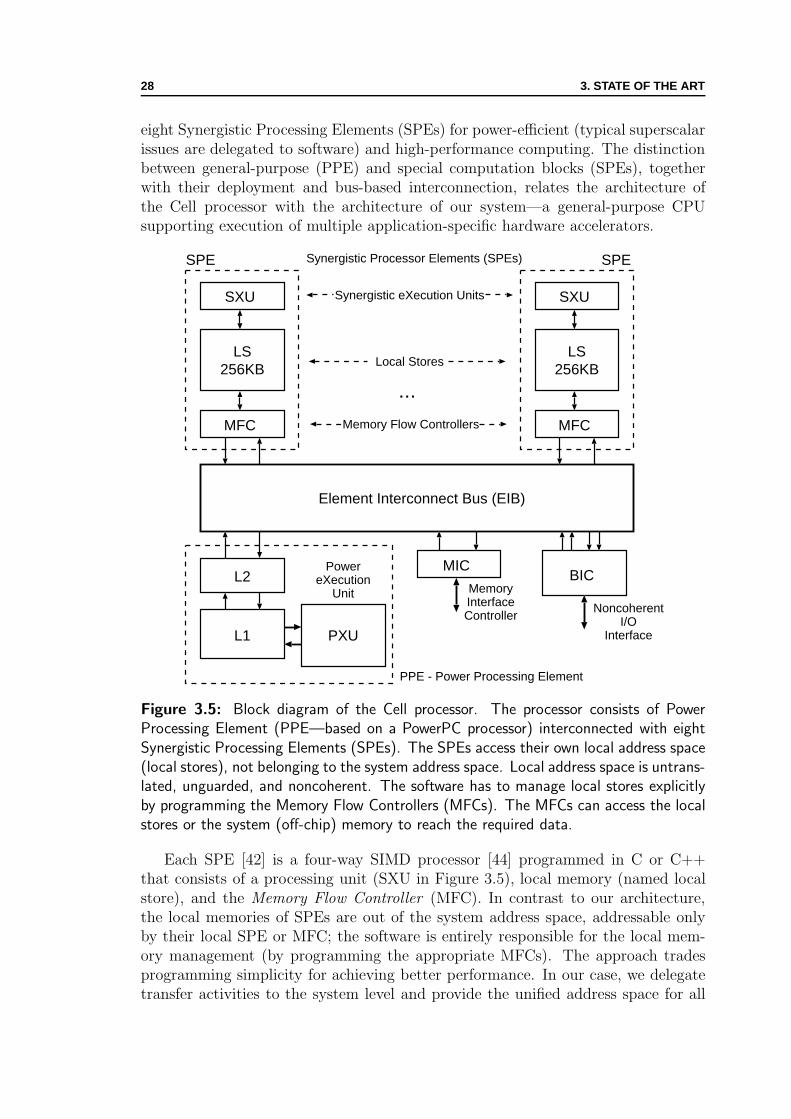
28 3. STATE OF THE ART
eight Synergistic Processing Elements (SPEs) for power-efficient (typical superscalarissues are delegated to software) and high-performance computing. The distinctionbetween general-purpose (PPE) and special computation blocks (SPEs), togetherwith their deployment and bus-based interconnection, relates the architecture ofthe Cell processor with the architecture of our system—a general-purpose CPUsupporting execution of multiple application-specific hardware accelerators.
LS256KB
SXU
...
Element Interconnect Bus (EIB)
Synergistic Processor Elements (SPEs)
L2Power
eXecutionUnit
L1 PXU
MICBIC
MemoryInterfaceController
SPE
MFC
LS256KB
SXU
SPE
MFC
Synergistic eXecution Units
Local Stores
PPE - Power Processing Element
NoncoherentI/O
Interface
Memory Flow Controllers
Figure 3.5: Block diagram of the Cell processor. The processor consists of PowerProcessing Element (PPE—based on a PowerPC processor) interconnected with eightSynergistic Processing Elements (SPEs). The SPEs access their own local address space(local stores), not belonging to the system address space. Local address space is untrans-lated, unguarded, and noncoherent. The software has to manage local stores explicitlyby programming the Memory Flow Controllers (MFCs). The MFCs can access the localstores or the system (off-chip) memory to reach the required data.
Each SPE [42] is a four-way SIMD processor [44] programmed in C or C++that consists of a processing unit (SXU in Figure 3.5), local memory (named localstore), and the Memory Flow Controller (MFC). In contrast to our architecture,the local memories of SPEs are out of the system address space, addressable onlyby their local SPE or MFC; the software is entirely responsible for the local mem-ory management (by programming the appropriate MFCs). The approach tradesprogramming simplicity for achieving better performance. In our case, we delegatetransfer activities to the system level and provide the unified address space for all
3.3. HARDWARE AND SOFTWARE INTERFACING 29
accelerators. We also address improving performance of memory transfers, but ina user transparent fashion (the end user is completely screened), through runtimeoptimisations such as prefetching.
3.2.3 Managing FPGA Resources
Different research groups have recognised the significance of managing FPGA realestate. Reconfigurable logic is a computational resource that codesigned applica-tions can use for accelerating their execution. A resource manager determines howthe applications running at the same time use the reconfigurable resource. It alsomakes sure to load an accelerator configuration in the reconfigurable logic beforea particular application refers to it. In his work on a virtual hardware OS, Breb-ner [20, 21] defines swappable logic units and proposes delegating their managementto an OS. The ultimate goal is to screen the end user from the problems introducedby the finite amount of available reconfigurable logic. Accordingly, Dales [34] hasshown another example of reconfigurable hardware virtualisation. His proposal de-scribes an architecture relying on the OS to share dynamically the reconfigurablelogic among applications. In his case, the OS supports mapping from the virtualto the physical resource. The type of virtualisation we introduce addresses theinterfacing between the CPU and the reconfigurable accelerators rather than thereconfigurable lattice itself.
Dynamic partitioning of the reconfigurable logic and configuration schedulingare advanced tasks of the resource manager. Walder and Platzner [123] have in-vestigated online scheduling for block-partitioned reconfigurable devices. Similarly,Caspi et al. [26] have examined dynamic scheduling for a stream-oriented computa-tion model. Finally, Fu and Compton [45] have proposed, for a computation modelclosest to ours, extending an OS with support for scheduling and runtime bind-ing of computation kernels implemented in reconfigurable hardware. In our case, webuild the execution environment for reconfigurable hardware accelerators within theunified OS process, and we do not address partitioning and scheduling. Although,for the moment, we assume that the configuration of the FPGA does not changeduring application lifetime, our future OS extensions may incorporate sophisticatedalgorithms proposed by the related work. The existing approaches presented in thissection are orthogonal and complementary to our work—future systems may haveto implement both.
3.3 Hardware and Software Interfacing
Typical solutions [72, 84, 112] for hardware accelerator interfacing with softwareexpose the communication to the programmer through a limited-size interface mem-ory mapped to the user space. For example, Leong et al. [72] use a memory slotinterface for communication between the CPU and the hardware accelerator. Onthe other side, our approach completely liberates the programmer of communica-tion details, since the OS does memory transfers implicitly hiding them from theend user. Caspi et al. [26, 27] and Nollet et al. [89] introduce more sophisticated
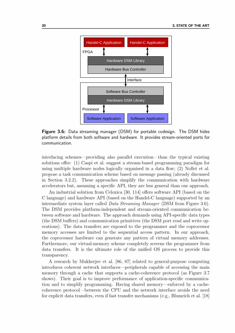
30 3. STATE OF THE ART
Handel-C Application Handel-C Application
Hardware DSM Library
Hardware Bus Controller
Hardware DSM Library
Software Bus Controller
Software Application Software Application
Interface
FPGA
Processor
Figure 3.6: Data streaming manager (DSM) for portable codesign. The DSM hidesplatform details from both software and hardware. It provides stream-oriented ports forcommunication.
interfacing schemes—providing also parallel execution—than the typical existingsolutions offer: (1) Caspi et al. suggest a stream-based programming paradigm forusing multiple hardware nodes logically organised in a data flow; (2) Nollet et al.propose a task communication scheme based on message passing (already discussedin Section 3.2.2). These approaches simplify the communication with hardwareaccelerators but, assuming a specific API, they are less general than our approach.
An industrial solution from Celoxica [30, 114] offers software API (based on theC language) and hardware API (based on the Handel-C language) supported by anintermediate system layer called Data Streaming Manager (DSM from Figure 3.6).The DSM provides platform-independent and stream-oriented communication be-tween software and hardware. The approach demands using API-specific data types(the DSM buffers) and communication primitives (the DSM port read and write op-erations). The data transfers are exposed to the programmer and the coprocessormemory accesses are limited to the sequential access pattern. In our approach,the coprocessor hardware can generate any pattern of virtual memory addresses.Furthermore, our virtual-memory scheme completely screens the programmer fromdata transfers. It is the ultimate role of the unified OS process to provide thistransparency.
A research by Mukherjee et al. [86, 87] related to general-purpose computingintroduces coherent network interfaces—peripherals capable of accessing the mainmemory through a cache that supports a cache-coherence protocol (as Figure 3.7shows). Their goal is to improve performance of application-specific communica-tion and to simplify programming. Having shared memory—enforced by a cache-coherence protocol—between the CPU and the network interface avoids the needfor explicit data transfers, even if fast transfer mechanisms (e.g., Blumrich et al. [18]
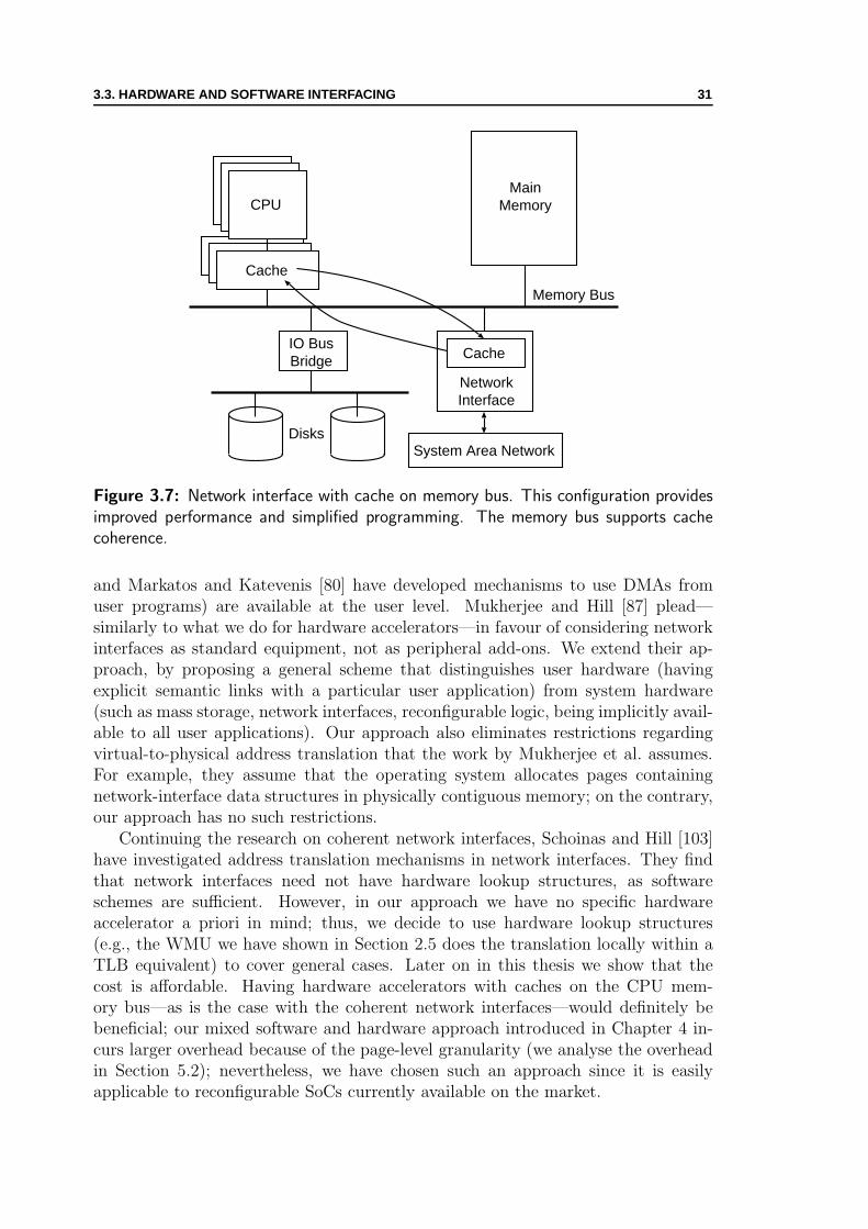
3.3. HARDWARE AND SOFTWARE INTERFACING 31
Memory Bus
MainMemory
NetworkInterface
CacheIO BusBridge
Disks
CPU
Cache
System Area Network
Figure 3.7: Network interface with cache on memory bus. This configuration providesimproved performance and simplified programming. The memory bus supports cachecoherence.
and Markatos and Katevenis [80] have developed mechanisms to use DMAs fromuser programs) are available at the user level. Mukherjee and Hill [87] plead—similarly to what we do for hardware accelerators—in favour of considering networkinterfaces as standard equipment, not as peripheral add-ons. We extend their ap-proach, by proposing a general scheme that distinguishes user hardware (havingexplicit semantic links with a particular user application) from system hardware(such as mass storage, network interfaces, reconfigurable logic, being implicitly avail-able to all user applications). Our approach also eliminates restrictions regardingvirtual-to-physical address translation that the work by Mukherjee et al. assumes.For example, they assume that the operating system allocates pages containingnetwork-interface data structures in physically contiguous memory; on the contrary,our approach has no such restrictions.
Continuing the research on coherent network interfaces, Schoinas and Hill [103]have investigated address translation mechanisms in network interfaces. They findthat network interfaces need not have hardware lookup structures, as softwareschemes are sufficient. However, in our approach we have no specific hardwareaccelerator a priori in mind; thus, we decide to use hardware lookup structures(e.g., the WMU we have shown in Section 2.5 does the translation locally within aTLB equivalent) to cover general cases. Later on in this thesis we show that thecost is affordable. Having hardware accelerators with caches on the CPU mem-ory bus—as is the case with the coherent network interfaces—would definitely bebeneficial; our mixed software and hardware approach introduced in Chapter 4 in-curs larger overhead because of the page-level granularity (we analyse the overheadin Section 5.2); nevertheless, we have chosen such an approach since it is easilyapplicable to reconfigurable SoCs currently available on the market.
32 3. STATE OF THE ART
3.4 Prefetching Techniques
We employ a dynamic prefetching technique (explained in Section 4.4) in the systemabstraction layer supporting unified memory for user software and user hardware.The technique is motivated by extensive related work on prefetching. In this section,we mention just few principal researches on prefetching that is applied, or could beapplied, to our approach.
Hardware and software prefetching techniques were originally developed for cachememories to support different memory access patterns. Jouppi [63] has introducedstream buffers, as an extension of tag-based prefetching, for simple but effectiveprefetching for sequential memory accesses. Following Jouppi’s work, Palacharlaand Kessler [90] have proposed several enhancements for stream buffers. Othertechniques exist that cover nonsequential memory accesses (e.g., Roth, Moshovos,and Sohi [99] address recursive techniques that can fit pointer-chasing memory ac-cesses, while Solihin, Lee, and Torrellas [109] show correlation-based prefetching foruser-level threads). In the field of reconfigurable computing, Lange and Koch [66]have used hardware prefetching techniques for configurable processors.
Apart from caching, researchers have used prefetching techniques for efficientvirtual memory management. For example, Saulsbury, Dahlgren, and Stenstromhave relied on a hardware technique to speculatively preload the TLB and avoidpage faults. Similarly, Bala, Kaashoek, and Weihl [14] have investigated a softwaretechnique to prefetch virtual memory pages for user applications.
The prefetching technique that we use within our unified OS process is inits essence a dynamic software technique with limited hardware support. It ismotivated—but not limited to—by Jouppi’s stream buffers. We have implementedthe dynamic prefetching in such a way that future extensions of our architecture caneasily apply the techniques mentioned in this section. The strongest point of ourdynamic prefetching is the transparency: neither user software nor user hardwareare aware of its presence, the optimisation is completely done at the system level.
3.5 High-level Language Synthesis
A considerable amount of research on synthesis is available in the hardware and soft-ware codesign literature [37]. We limit the comparison of our unrestricted synthesisapproach only to published results on high-level language synthesis; closer to ourcase study shown in Section 6.3, we also consider existing approaches of high-levelsynthesis for virtual machines.
Hardware synthesis from high-level programming languages, especially for di-alects of C and C++, has been a challenging topic for a long time [36, 40]. Forsynthesising hardware from languages related to C and C++, researchers, as wellas the industry, have adopted two major approaches: (1) extending the originallanguage [29, 46, 53, 131] and making it closer to hardware description languages(e.g., adding language constructs such as concurrency, reactivity, variable bitwidth,special data types); and (2) restricting the original language [47, 92, 106, 108] to easethe mapping to the register transfer level (e.g., excluding language constructs such as

3.5. HIGH-LEVEL LANGUAGE SYNTHESIS 33
Suif Front-End
Optimise; Convert
Optimise
Async Back-End
VerilogCode
CCode
Control-FlowGraph
PegasusSSA
CA
SH
Figure 3.8: Compiler for Application-Specific Hardware (CASH). Using a Static SingleAssignment (SSA) form and an asynchronous back end producing Verilog code, thecompiler synthesises application-specific accelerators from the input C code.
pointers, dynamic allocation, function calls, and recursion). Having our unified OSprocess with unified virtual memory and execution transfers, there is no restrictionon the input code; practically, a synthesis flow based on our unified OS process cantreat any high-level language construct. We do not consider special hardware de-scription languages originating from standard programming languages; we supposethat the synthesiser is capable of extracting enough parallelism from the originalcode; nevertheless, if the programmer decides to write explicitly-parallel code (e.g.,using a multithreaded programming paradigm), a synthesis flow based on the unifiedOS process with multithreading support (we present the multithreading extensionto the unified process in Chapter 7) will be able to handle it as well.
In their research on spatial computation, Budiu et al. [23] use a computationmodel closest to ours. Assuming an asynchronous coprocessor-based model with amonolithic memory shared with the CPU, they develop a compiler flow for gener-ating application-specific hardware from C-program kernels. On average, the Me-diabench applications [68] run slower on hardware generated by their flow than ona superscalar machine [24]. However, they report significant power savings (up tothree orders of magnitude). Figure 3.8 shows their CASH (Compiler for Application-Specific Hardware) synthesis flow. The flow uses Suif [127] as a front-end to trans-form the input C program into a control-flow graph. The next pass of the flowconverts the control-flow graph to an extended SSA (Static Single Assignment) in-

34 3. STATE OF THE ART
termediate representation (Pegasus in Figure 3.8). After the final optimisations, theback-end produces the Verilog output for an asynchronous circuit corresponding tothe input C code. Although Budiu et al. ease the translation of C into hardwareby assuming a memory hierarchy like in general-purpose systems, the circuits gen-erated by CASH cannot handle system calls. In our case, such limitation does notexist. The unified OS process allows user hardware to invoke system services (asSection 6.2 shows).
We also consider research on automated synthesis of memory subsystems to berelated to our work. For example, Wutack et al. [129] use a compile-time analysisto generate distributed memory structures with custom memory managers. On thecontrary, our solution is a general-purpose and a centralised one: memory manage-ment is performed by the OS at runtime and the virtual memory space is unique forall accelerators. This, however, does not exclude possible future implementations ofour system with distributed management of the virtual memory.
The unified OS process enables synthesis of high-level language concepts likememory allocation, function calls, and recursion [122]. We implement a synthesisflow for virtual machines as a case study. Researchers have used software [115] andhardware [67, 73] approaches to accelerate code execution in virtual machines. Inthe case of Java Virtual Machines (JVMs), industrial solutions exist that supportlimited or complete subset of JVM instructions (Java bytecode) directly in hard-ware [73] (e.g., PicoJava from Sun, Jazelle from ARM, or DeCaf from Aurora VLSI).The approach improves execution times of Java programs, but it is highly depen-dent on the used JVM. Other authors have addressed the optimisation problem ata higher level, by implementing Java methods in reconfigurable hardware [43, 67].However, these solutions are usually dependent on the underlying reconfigurableplatform and the used JVM. In contrast to both approaches, our solution relieson the unified OS process for codesigned applications that provides portability andseamless interfacing of reconfigurable accelerators (critical Java bytecode methodsmigrated to hardware). Our approach can be used with any JVM which conformsto the Java platform standard. Moreover, our extension to the JVM execution en-vironment allows running of these accelerators without any modification of eithercompiled Java bytecode or Java source.
Chapter 4Virtual Memoryfor Hardware Accelerators
And now for something completely different.—The Announcer, Monthy Python’s Flying Circus
Play it again, Sam.—Rick Blaine (what he never said), Casablanca
IN this chapter, we show which system software and system hardware extensionsare necessary to provide unified virtual memory for codesigned applications. As
already mentioned in Chapter 2, we choose a mixed software-and-hardware approachthat enables hardware accelerators sharing the virtual memory with user software.We present our architecture (Section 4.1) and we explain its basic components (sys-tem hardware in Section 4.2 and system software in Section 4.3). In Section 4.4,we show simple extensions to our architecture that support system-level runtimeoptimisations for codesigned applications.
4.1 System Architecture
Our approach primarily relies on system software and system hardware extensions.Figure 4.1 shows the system support required by user software and user hard-ware for cohabiting within the same user process. The Memory Management Unit(MMU) translates memory addresses generated by the user software—executed onthe CPU—from virtual addresses to physical addresses of the main memory. TheVirtual Memory Manager (VMM) of the OS manages and controls the translation.
We add an MMU equivalent (the WMU introduced in Chapter 2) as a systemhardware support for the translation of virtual memory addresses generated bythe user hardware—executed on the hardware accelerator. We also extend the OSwith a virtual memory manager for hardware accelerators (Virtual Memory for userhardWare—VMW—manager in Figure 4.1). It manages the translation done bythe WMU (similarly as the VMM does with the MMU) and provides a system callinterface between software and hardware.
35

36 4. VIRTUAL MEMORY FOR HARDWARE ACCELERATORS
UserSW
Virtual Memory
UserHW
A B C SIZE
Operating System
VMM VMW
User Process
... MMU
CPU
WMU
HWAcc
Main Memory
Local Memory
System Bus
Sys
tem
Har
dwar
eS
yste
mS
oftw
are
Use
rA
pplic
atio
n
User HardwareUser Software
Sys
Cal
lIn
terf
ace
Figure 4.1: Support architecture for unified memory abstraction at the applicationlevel. The OS provides the memory abstraction and manages the translation done bythe MMU and the WMU.
It is worth noticing that the system bus interconnecting the CPU and the hard-ware accelerator does not have any support for memory coherence (for the sake ofsimplicity, Figure 4.1 does not show the real memory hierarchy of the CPU—thecaching is, of course, present). We completely rely on the OS to perform this task;although this fact may affect system performance (as discussed in the analysis inSection 5.2), the approach is applicable to a wide range of reconfigurable SoCs.Furthermore, the experimental results (in Section 5.3) show that the introducedoverhead is acceptable.
4.2 Hardware Interface to Virtual Memory
The WMU translates virtual addresses generated by user hardware to physical ad-dresses of an on-chip, local memory, acting as a software managed cache (shown inFigure 4.1). Apart the translation, the WMU decouples the design of application-specific hardware accelerators from the host platform: it defines a standardised hard-ware interface for the virtual memory-enabled hardware accelerators. The WMUalso supports parameter exchange between software and hardware, and provides away for user hardware to call back software and invoke system calls (as we demon-strate in Chapter 6).
The WMU—being a platform specific component, as its interfacing dependson the system bus specification of a particular platform and its implementation
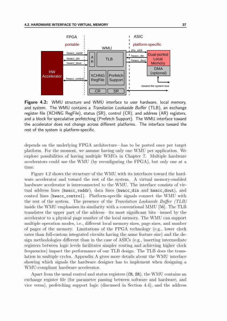
4.2. HARDWARE INTERFACE TO VIRTUAL MEMORY 37
AR
TLB
SRCR
HWAccelerator
WMUhwacc_vaddr
hwacc_din
hwacc_control
ASICFPGA
portable platform-specific
Dual-portedLocal
Memory
XCHNGRegFile
PrefetchSupport
hwacc_dout
toward the system bus
phy_addr
hwacc_din
hwacc_dout
DMA(optional)
Figure 4.2: WMU structure and WMU interface to user hardware, local memory,and system. The WMU contains a Translation Lookaside Buffer (TLB), an exchangeregister file (XCHNG RegFile), status (SR), control (CR), and address (AR) registers,and a block for speculative prefetching (Prefetch Support). The WMU interface towardthe accelerator does not change across different platforms. The interface toward therest of the system is platform-specific.
depends on the underlying FPGA architecture—has to be ported once per targetplatform. For the moment, we assume having only one WMU per application. Weexplore possibilities of having multiple WMUs in Chapter 7. Multiple hardwareaccelerators could use the WMU (by reconfiguring the FPGA), but only one at atime.
Figure 4.2 shows the structure of the WMU with its interfaces toward the hard-ware accelerator and toward the rest of the system. A virtual memory-enabledhardware accelerator is interconnected to the WMU. The interface consists of vir-tual address lines (hwacc_vaddr), data lines (hwacc_din and hwacc_dout), andcontrol lines (hwacc_control). Platform-specific signals connect the WMU withthe rest of the system. The presence of the Translation Lookaside Buffer (TLB)inside the WMU emphasises its similarity with a conventional MMU [56]. The TLBtranslates the upper part of the address—its most significant bits—issued by theaccelerator to a physical page number of the local memory. The WMU can supportmultiple operation modes, i.e., different local memory sizes, page sizes, and numberof pages of the memory. Limitations of the FPGA technology (e.g., lower clockrates than full-custom integrated circuits having the same feature size) and the de-sign methodologies different than in the case of ASICs (e.g., inserting intermediateregisters between logic levels facilitates simpler routing and achieving higher clockfrequencies) impact the performance of our TLB design. The TLB does the trans-lation in multiple cycles. Appendix A gives more details about the WMU interfaceshowing which signals the hardware designer has to implement when designing aWMU-compliant hardware accelerator.
Apart from the usual control and status registers (CR, SR), the WMU contains anexchange register file (for parameter passing between software and hardware, andvice versa), prefetching support logic (discussed in Section 4.4), and the address
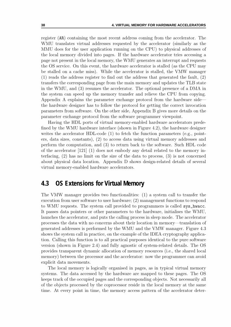
38 4. VIRTUAL MEMORY FOR HARDWARE ACCELERATORS
register (AR) containing the most recent address coming from the accelerator. TheWMU translates virtual addresses requested by the accelerator (similarly as theMMU does for the user application running on the CPU) to physical addresses ofthe local memory divided into pages. If the hardware accelerator tries accessing apage not present in the local memory, the WMU generates an interrupt and requeststhe OS service. On this event, the hardware accelerator is stalled (as the CPU maybe stalled on a cache miss). While the accelerator is stalled, the VMW manager(1) reads the address register to find out the address that generated the fault, (2)transfers the corresponding page from the main memory and updates the TLB statein the WMU, and (3) resumes the accelerator. The optional presence of a DMA inthe system can speed up the memory transfer and relieve the CPU from copying.Appendix A explains the parameter exchange protocol from the hardware side—the hardware designer has to follow the protocol for getting the correct invocationparameters from software. On the other side, Appendix B gives more details on theparameter exchange protocol from the software programmer viewpoint.
Having the HDL ports of virtual memory-enabled hardware accelerators prede-fined by the WMU hardware interface (shown in Figure 4.2), the hardware designerwrites the accelerator HDL-code (1) to fetch the function parameters (e.g., point-ers, data sizes, constants), (2) to access data using virtual memory addresses andperform the computation, and (3) to return back to the software. Such HDL codeof the accelerator [121] (1) does not embody any detail related to the memory in-terfacing, (2) has no limit on the size of the data to process, (3) is not concernedabout physical data location. Appendix D shows design-related details of severalvirtual memory-enabled hardware accelerators.
4.3 OS Extensions for Virtual Memory
The VMW manager provides two functionalities: (1) a system call to transfer theexecution from user software to user hardware; (2) management functions to respondto WMU requests. The system call provided to programmers is called sys_hwacc.It passes data pointers or other parameters to the hardware, initialises the WMU,launches the accelerator, and puts the calling process in sleep mode. The acceleratorprocesses the data with no concerns about their location in memory—translation ofgenerated addresses is performed by the WMU and the VMW manager. Figure 4.3shows the system call in practice, on the example of the IDEA cryptography applica-tion. Calling this function is to all practical purposes identical to the pure softwareversion (shown in Figure 2.4) and fully agnostic of system-related details. The OSprovides transparent dynamic allocation of memory resources (i.e., the shared localmemory) between the processor and the accelerator: now the programmer can avoidexplicit data movements.
The local memory is logically organised in pages, as in typical virtual memorysystems. The data accessed by the hardware are mapped to these pages. The OSkeeps track of the occupied pages and the corresponding objects. Not necessarily allof the objects processed by the coprocessor reside in the local memory at the sametime. At every point in time, the memory access pattern of the accelerator deter-

4.3. OS EXTENSIONS FOR VIRTUAL MEMORY 39
/* Virtual memory-enabled accelerator version */
void idea cipher cp (IDEA block *A, IDEA block *B, int n64) {param.params no = 3;
param.flags = 0;
param.p[0] = A;
param.p[1] = B;
param.p[2] = n64;
sys hwacc (IDEA HW, ¶m);
}
Figure 4.3: Calling the IDEA hardware accelerator through the sys hwacc system call.The programmer initialises the parameter passing structure and invokes the system call.
Handle Fault
Copy Dirties
ScheduleFault Page
ServiceMemory Fetch
Requests
Interrupt Request
Go to Sleep
Fetcher
Handle CallbackHandle Finish
Return to User
Status?
no
faultback to user
Finish?yes
Figure 4.4: Basic VMW interrupt handler. Receiving a back-to-user interrupt, themanager prepares the execution transfer back to user software (either for an acceleratorcompletion or for a software callback). For a fault interrupt, the manager transfers themissing page to the local memory.
mines the occupation of the local memory pages. The accelerator can address anyword of the user address space (including stack and heap dynamic memory regions).However, through memory protection policies, the OS prevents the accelerator fromaccessing forbidden memory regions (such as regions containing software code).
Figure 4.4 shows the basic architecture of the VMW interrupt handler. When aninterrupt arrives from the WMU, the manager checks the status register to distin-guish the two possible requests: (1) page fault—the hardware attempted an accessto an address not currently in the local memory; (2) back to user—the hardwarerequests the transfer of the execution back to software.
Page Fault. Since the requested page is not in the local memory, the OS has torearrange the current memory mapping, in order to resolve the fault. It may happenthat all pages of the local memory are already in use. In this case, the VMW managerselects a page for eviction (different replacement policies are possible). The managerensures that the user memory reflects correctly the state of the local memory; if thepage selected for eviction is dirty, its contents are copied back to the user-spacememory and the page is anew allocated for the missing data; the missing data pageis scheduled for transfer; the manager part called Fetcher copies the missing data

40 4. VIRTUAL MEMORY FOR HARDWARE ACCELERATORS
from the user-space memory and updates the WMU state; afterward, the OS allowsthe WMU to restart the translation and lets the accelerator exit from the stalledstate and continue the execution.
One shall notice a possible overhead—Section 5.2 discusses it further—that mayappear for write faults because of page-level granularity of the local memory. Theoverhead is likely to appear for hardware accelerators with stream-based memoryaccesses. On a write fault (i.e., the accelerator tries writing to an address not presentin the local memory), the OS has to transfer the whole page to the local memory,even if future memory accesses of the accelerator may thoroughly overwrite its con-tents (i.e., write to each single word of the page). This would mean that the timespent on transferring the page from the main memory may be wasted, just allocatingthe page in the local memory—without copying the page for a write fault—couldsuffice; however, such a speculative act would require in-advance knowledge that theaccelerator never reads from the page.
Back to User. If such a request arrives from the WMU, the VMW man-ager checks if the end of the accelerator operation is reported (“Finish?” checkin Figure 4.4). If true, the manager transfers back the execution to user software,immediately after the sys_hwacc system call in the original program (e.g., it wouldbe the function return in Figure 4.3). On the contrary, if the arrived request is fora software callback (i.e., the hardware accelerator invokes a system call or a soft-ware function), the manager transfers the execution to the corresponding function,which is out of the normal program execution flow. In Chapter 6, we present howthe VMW manager enables the execution transfer. In both cases, before transfer-ring the execution back to software, the VMW manager copies back to the userspace all dirty pages currently residing in the local memory. This is a conservativeapproach—assuming that the callback function might need any page from the lo-cal memory–which is not necessarily the most efficient one. A possible optimisationcould delay the transfer of a page to the moment when the callback function accessesthe page.
4.4 Dynamic Optimisations in Abstraction Layer
The involvement of system software in execution steering simplifies hardware andsoftware interfacing and unloads software programmers and hardware designers fromthe burdens of the typical approaches. The presence of the runtime steering inthe system software also allows dynamic optimisations that can improve the per-formance, in a manner completely transparent for users, without any change inapplication source code.
In this section, we present the basic motivation for applying OS-based prefetchtechniques. Afterward, we discuss the details of hardware and software require-ments to implement a prefetching system for virtual-memory-enabled hardware ac-celerators. We show the benefits of our approach and showcase several examples ofcodesigned applications through experiments in Chapter 5.
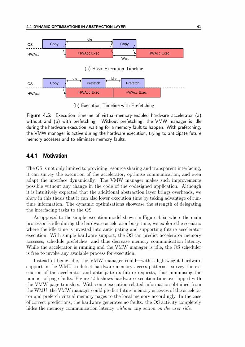
4.4. DYNAMIC OPTIMISATIONS IN ABSTRACTION LAYER 41
HWAcc Exec
Copy
WaitHWAcc
OS Copy
HWAcc Exec
Idle
(a) Basic Execution Timeline
HWAcc Exec
Copy
HWAcc
OS
HWAcc Exec
IdlePrefetch Prefetch
Idle
(b) Execution Timeline with Prefetching
Figure 4.5: Execution timeline of virtual-memory-enabled hardware accelerator (a)without and (b) with prefetching. Without prefetching, the VMW manager is idleduring the hardware execution, waiting for a memory fault to happen. With prefetching,the VMW manager is active during the hardware execution, trying to anticipate futurememory accesses and to eliminate memory faults.
4.4.1 Motivation
The OS is not only limited to providing resource sharing and transparent interfacing;it can survey the execution of the accelerator, optimise communication, and evenadapt the interface dynamically. The VMW manager makes such improvementspossible without any change in the code of the codesigned application. Althoughit is intuitively expected that the additional abstraction layer brings overheads, weshow in this thesis that it can also lower execution time by taking advantage of run-time information. The dynamic optimisations showcase the strength of delegatingthe interfacing tasks to the OS.
As opposed to the simple execution model shown in Figure 4.5a, where the mainprocessor is idle during the hardware accelerator busy time, we explore the scenariowhere the idle time is invested into anticipating and supporting future acceleratorexecution. With simple hardware support, the OS can predict accelerator memoryaccesses, schedule prefetches, and thus decrease memory communication latency.While the accelerator is running and the VMW manager is idle, the OS scheduleris free to invoke any available process for execution.
Instead of being idle, the VMW manager could—with a lightweight hardwaresupport in the WMU to detect hardware memory access patterns—survey the ex-ecution of the accelerator and anticipate its future requests, thus minimising thenumber of page faults. Figure 4.5b shows hardware execution time overlapped withthe VMW page transfers. With some execution-related information obtained fromthe WMU, the VMW manager could predict future memory accesses of the accelera-tor and prefetch virtual memory pages to the local memory accordingly. In the caseof correct predictions, the hardware generates no faults: the OS activity completelyhides the memory communication latency without any action on the user side.
42 4. VIRTUAL MEMORY FOR HARDWARE ACCELERATORS
CAM RAMVirtPage No PhysPage No
Invalid
Dirty
Hit
PageAccess
Invalid
TLB
1-hot
AMRAIR
"00000100"
00
00
00
10
00101
1
0
0
01
Figure 4.6: Page access detection in the WMU. On a hit in the Content AddressableMemory (CAM), 1-hot bit lines will set the corresponding bit in the Access IndicatorRegister (AIR). If the mask (Access Monitor Register—AMR) allows the access, theWMU raises an interrupt. By reading the AIR register, the OS can determine whichpages the accelerator has accessed.
4.4.2 Hardware and Software Extensions
We introduce a simple extension—two 32-bit registers and few tens of logic gates—to the WMU that supports the detection of a page access. Figure 4.6 containsthe internal organisation of the WMU related to address translation. The VMWsets the appropriate bits of the Access Monitor Register (AMR), indicating to theWMU which page accesses to report (Table A.1 from Appendix A shows how manypages the WMU typically supports). If there is a match in the Content AddressableMemory (CAM), the 1-hot bit lines are used to set a bit—corresponding to theaccessed page—in the Access Indicator Register (AIR). If the mask in the AMRallows (i.e., the VMW manager requests monitoring the access event), the WMUwill report the page access by raising an access interrupt. While the access interruptis being handled, there is no need to stop the accelerator; the VMW manager andthe accelerator can run in parallel. The OS actions need not be limited to thissimple access detection mechanism. A more sophisticated but still reasonably simplehardware can be employed in order to support detection of more complex memoryaccess patterns.
We extend the VMW manager and its interrupt handler (shown in Figure 4.4) tosupport the prediction of future memory accesses and speculative prefetching (Fig-ure 4.7 shows the extensions). The three main design components of the extendedVMW manager [120] are: (1) initialisation and interrupt handling; (2) prediction offuture accesses (Predictor); (3) fetching of pages from main memory (Fetcher). Fora fault interrupt, after scheduling a transfer of a fault page, the OS invokes the pre-dictor module which predicts future accesses and schedules their transfers. For anaccess interrupt, the OS again invokes the predictor module to validate or confuteits past predictions, and schedule future transfers. The predictor uses a simple buteffective—in the case of stream-based memory accesses—prefetching policy [120]based on the previous work on stream-buffers for cache memories [63, 90].
The Predictor. It attempts to guess future memory accesses and to schedulepage transfers. The only input parameters to the predictor are fault addresses and

4.4. DYNAMIC OPTIMISATIONS IN ABSTRACTION LAYER 43
Copy Dirties
Interrupt Request
Go to Sleep
Fetcher
Handle CallbackHandle Finish
Return to User
Status?
no
accessback to user
Finish?yes
Schedule Pred Page
Handle Fault
ServiceMemory Fetch
Requests
Handle Access
Schedule Pred Page
Predictor
Schedule Fault Page
Fault-based Prediction Acces-based Prediction
fault
Figure 4.7: Extended VMW manager for speculative transfers. Predictor schedulesspeculative pages for transfer. Predictions are fault-based (a new stream detected) andaccess-based (a stream access confirmed). Both initiate speculatively prefetching a newpage.
accessed-page numbers—there is no information about the state of the hardwareaccelerator. The approach is similar to classic prefetching techniques where no in-formation is available about the instructions issued by the main processor [90] butonly the addresses on the bus. A simple predictor assumes that for each fault a newstream is detected; thus, it requires a stream buffer allocation (i.e., a circular bufferbuilt of a pair of local memory pages, as Figure 4.8 illustrates) and it schedulesa speculative prefetch for the virtual page following the missing one. By settingappropriately the AMR, it ensures that the WMU hardware shall report the firstaccess to the speculatively-loaded page. When the WMU reports the access, theinterrupt handler invokes the predictor again and, with this information confirming
free
SB Pool SB PoolAMR AMR0
1
000
000
0
0
00
00
1
1
free
A
S
A
SA
S
NA - Not AllocatedNA - Not Allocated
NANANA
NANANA
SB0B
SB0A
NANA
NANA
SB0ASB1A
SB1BSB0B
Figure 4.8: Stream Buffer (SB) allocation and the AMR. On a fault, a pair of pages(SB) is allocated. The fault page is active (A); it is being accessed by the accelerator;the prefetched page is speculative (S). The AMR helps to detect accesses to (S) pages.

44 4. VIRTUAL MEMORY FOR HARDWARE ACCELERATORS
the speculation, further prefetches are scheduled in the same fashion. Each specula-tive prefetch is designated to its corresponding stream buffer. While the acceleratoraccesses the active page (A in Figure 4.8), the VMW prefetches the speculative one(S in Figure 4.8). Ideally, for a correctly-guessed memory access stream and goodtiming of the prefetching, only one fault per stream should appear: the prefetchingshould prevent all other faults to appear.
Although for the moment we use a simple, software-managed and hardware-supported, stream-buffer-based technique [63, 90] that handles efficiently stream-based memory accesses, other techniques that cover nonsequential memory accesses(e.g., recursive [99], and correlation-based techniques [109]) could also be applied,with appropriate extensions in the system software (the VMW manager) and systemhardware (the WMU). More importantly, the presented technique is completelytransparent to the user. On the experimental results presented in Chapter 5, weshow the effectiveness of the prefetching technique.
Chapter 5Unified MemoryPerformance and Overheads
Mrki Vuce, podigni brkove,Da ti vidju toke na prsima,Da prebrojim zrna od pusakahKolika ti toke izlomise!
O scowling Vuk, lift your moustache for meand let me see the breastplates on your chest,that I may count holes from rifle bullets,see how many of them broke up your plates!
—Njegos, The Mountain Wreath
THIS chapter introduces a performance metric for spatial computation whichwe use for performance and overhead analysis of existing approaches and our
unified memory scheme. Later on, we use the definition of the performance point-ers for experimental measurements. The measurements demonstrate the viabilityof our approach by showing (1) performance improvements the approach providescompared to the software-only applications and (2) limited overheads the approachintroduces compared to the existing approaches. The dynamic optimisations in thesystem abstraction layer facilitate an additional performance improvement—it isachieved without any user intervention on the application code.
5.1 Performance Metric for Heterogeneous Computing
Performance analysis of codesigned applications requires having a common metric.The metrics used for standard processors [50, 56, 83] are just partially applicableto codesigned applications. Such applications have heterogeneous code consisting ofuser software and user hardware—the existing metrics are only applicable to softwareparts of codesigned applications. We assume for the moment that the applicationexecution is sequential—user hardware and user software of a given application donot execute in parallel—and, later, we release this restriction in Chapter 7.
We do not address here the problem of how to partition the original application.We assume that the designer has already made the choice of critical code sections
45

46 5. UNIFIED MEMORY PERFORMANCE AND OVERHEADS
to be mapped to hardware in a way to maximise the overall performance. That iswhy, if not otherwise stated, we primarily consider the speedup of the critical codesection (refer to Section E.3 for an example). In general-purpose systems with asingle CPU, we can use the following performance equation for the overall executiontime (ET ) of a software-only critical section [56]:
ETSW = IC × CPI × TCPU , (5.1)
where IC stands for overall instruction count for the software code, CPI is an av-erage cycles per instruction for the code execution, and TCPU is the clock cycle timeof the CPU (i.e., the CPU clock period). The three parameters of Equation 5.1are subject to architectural, organisational, and implementation decisions of a CPUarchitect. They are interdependent: IC depends on ISA and compiler technology,CPI on CPU organisation and memory architecture, and TCPU on hardware tech-nology and CPU organisation.
Recalling the qualitative discussion from Section 2.2, an expression for the overallexecution time of the hardware accelerator1 is
ETHW =n∑
i=1
HTi +m∑
i=1
CTi = HT + CT , (5.2)
where CT is the total memory copy time, and HT is the total hardware executiontime. In the general case, the number of hardware execution intervals (n) and copyintervals (m) are different. Equation 5.2 is convenient for the hardware acceleratorwhere we can easily separate the time spent for memory transfers and the timespent in hardware execution (e.g., typical hardware accelerators with local memoryfrom Figure 2.3 and Figure 2.4b). In Equation 5.2, we neglect the time spenton the software side to manage the memory transfers, calculate buffer addresses,and iterate until the computation is over. The experimental results show (as wepresent in Section 5.3 of this chapter) that the management time is negligible forthe accelerators with simple memory access patterns.
The CPI parameter (from Equation 5.1) in the case of software gives an insightregarding the CPU architecture and organisation. There is no equivalent param-eter in Equation 5.2. To build a performance equation for hardware acceleratorswith the form equivalent to Equation 5.1, we introduce a new metric for spatialcomputation. We suppose the hardware designer implements the accelerator byparallelising the original software code of the critical section, thus preserving thecomplexity of the critical section and without changing the size of the problem [31].In this case, the total number of cycles for the accelerator execution depends onthe problem size—the number of data to be processed. This is not immediatelyvisible from Equation 5.2. Neither can the equation show the effectiveness of theperformed parallelisation: what is the number of data processed per cycle, how doesit relate to the execution support and memory hierarchy? Therefore, we introduceanother metric for spatial and data-flow computation that we base on Cycles PerDatum (CPD) in place of Cycles Per Instruction (CPI) used for CPUs. The CPD
1We assume that the time for the execution transfers from software to hardware is negligible.

5.2. OVERHEAD ANALYSIS 47
metric represents the average number of cycles spent by a hardware accelerator forprocessing the unit datum (a datum of the unit size; in our discussion, we considerit a 32-bit memory word). Using the CPD metric, the overall execution time of thehardware accelerator is
ETHW = DC × CPD × THW , (5.3)
where DC is the data count to be processed (i.e., the problem size) by the hardwareaccelerator, expressed in the number of memory words, and THW represents thehardware clock period—in the general case, THW is different from TCPU . The DCparameter is not affected by the VLSI (or FPGA) implementation of the criticalsection, be it semelective or multilective [101, 102] (i.e., no matter whether theaccelerator reads a particular input data from the local memory only once, whichmeans it is semelective, or multiple times, which means it is multilective, whatcounts is the problem size); however, where the semelectivity and multilectivity ofthe accelerator implementation matter is the CPD parameter. We show examplesof analytically calculating CPD from control-flow graphs and an example of its usein Appendix E.
Apart from convenient speedup estimation, the CPD metric gives an insightto the accelerator internal organisation: is the execution pipelined or not, what isthe cost (and influence on performance) of memory accesses, what is the numberof memory ports? We can draw parallels between CPI and CPD: (1) a computerarchitect strives to get both close to one; (2) having CPI or CPD smaller than oneindicates the presence of multiple issue or multiple memory ports, respectively; (3)both indicate the presence and efficiency of pipelining.
Similarly to an approach for general-purpose systems used for studying the effectsof memory hierarchies [56], we write Equation 5.3 in a form that clearly separatesthe pure hardware execution from the execution support (Section E.2 gives moredetails on the separation):
ETHW = DC × (CPDHW + CPDmemory) × THW , (5.4)
where CPDHW is the CPD value for the hardware accelerator assuming the idealmemory hierarchy (i.e., memory accesses introduce no stalls) and CPDmemory rep-resents the overhead incurred by the memory transfers. In the following section,we apply the same equation for calculating the overhead of virtual-memory-enabledhardware accelerators.
5.2 Overhead Analysis
In Equation 5.2, we have expressed the overall execution time (ETHW ) of a hardwareaccelerator. The time components HT and CT stand for pure hardware-executiontime and copy time. In Equation 5.4, we have developed another form of the per-formance equation; its factors CPDHW and CPDmemory designate cycles per datumfor pure hardware-execution (assuming ideal memory) and for the memory access

48 5. UNIFIED MEMORY PERFORMANCE AND OVERHEADS
CT1
Exec - HT1
MT1MT1 MT2
Wait
ST1
RT1
MT2
Exec - HT2
CT2
...
...OS
User HW
Figure 5.1: The operating system (OS) activities related to the hardware acceleratorexecution (User HW). The VMW manager of the OS sleeps (STi time) during thehardware execution (HTi time). The hardware stalls on a memory fault and waits forthe OS service. After some response time (RTi), the VMW manager reacts on theinterrupt event. It manages the translation data structures (MTi time) and copies therequired page to the local memory (CTi time). After some additional management, itresumes the hardware execution.
overhead (the price of managing—either in software or hardware—the memory hi-erarchy).
Based on Equations 5.2 and 5.4, we can express the execution time of virtual-memory-enabled hardware accelerators. Compared to the typical existing appro-aches, there are several sources of overhead in our scheme. The first one is relatedto the virtual address translation (limitations of the FPGA technology and designmethodologies different than in the case of ASICs result in a TLB which performsthe translation in multiple clock cycles, i.e., 4–6 in our implementations). Thus, theHardware execution Time (HT ) of virtual-memory-enabled accelerators is longerthan in the case of accessing the memory by physical addressing:
HTvirtual = t × HTtypical, (5.5)
where t > 1 is the translation overhead. It would be practically one, if the WMUswere implemented in ASIC, as a standard part of reconfigurable SoCs.
Figure 5.1 shows different time components during the execution of a virtual-memory-enabled hardware accelerator. The VMW manager in the OS managestranslation data structures (Management Time—MTi) and copies pages from/tothe user memory (Copy Time—CTi). When finished copying, it updates the datastructures MTi), invokes the kernel scheduler, and sleeps (Sleep Time—STi). Thehardware accelerator executes (Hardware Time—HTi) until it finishes or tries ac-cessing a page not present in the local memory. In both cases, it waits for the OSaction. The OS responds after some time (Response Time—RTi).
Having the OS responsible for the translation management brings MT and RT(the sums of corresponding MTi and RTi, respectively) as inherent overheads tothe performance equation. Sleep Time (ST = HTvirtual + RT ) represents the timeof the OS idleness, with respect to its actions on behalf of the accelerator. If weassume the same data transfer technique employed for a virtual-memory-enabledaccelerator and the corresponding typical one, the overall execution time (ET ) ofthe virtual-memory-enabled accelerator is
ETvirtual = t × HTtypical + RT︸ ︷︷ ︸Sleep time (ST )
+ c × CTtypical + MT, (5.6)
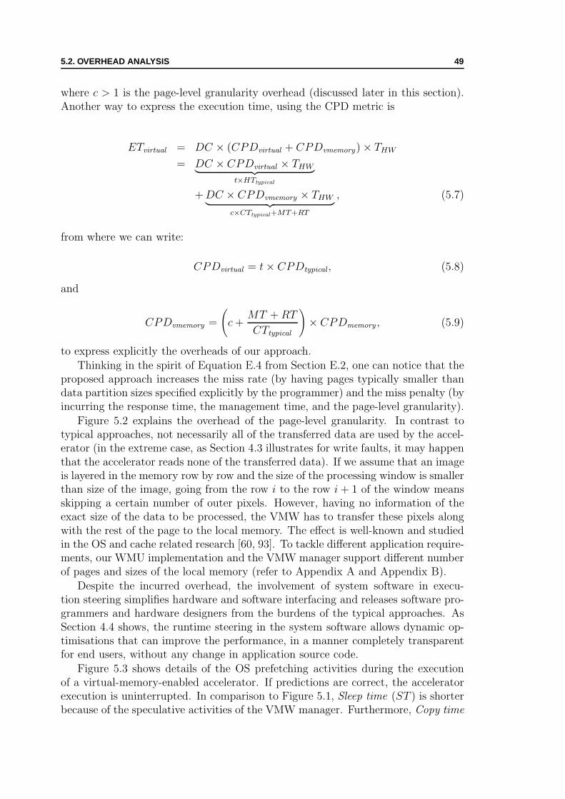
5.2. OVERHEAD ANALYSIS 49
where c > 1 is the page-level granularity overhead (discussed later in this section).Another way to express the execution time, using the CPD metric is
ETvirtual = DC × (CPDvirtual + CPDvmemory) × THW
= DC × CPDvirtual × THW︸ ︷︷ ︸t×HTtypical
+ DC × CPDvmemory × THW︸ ︷︷ ︸c×CTtypical+MT+RT
, (5.7)
from where we can write:
CPDvirtual = t × CPDtypical , (5.8)
and
CPDvmemory =
(c +
MT + RT
CTtypical
)× CPDmemory , (5.9)
to express explicitly the overheads of our approach.
Thinking in the spirit of Equation E.4 from Section E.2, one can notice that theproposed approach increases the miss rate (by having pages typically smaller thandata partition sizes specified explicitly by the programmer) and the miss penalty (byincurring the response time, the management time, and the page-level granularity).
Figure 5.2 explains the overhead of the page-level granularity. In contrast totypical approaches, not necessarily all of the transferred data are used by the accel-erator (in the extreme case, as Section 4.3 illustrates for write faults, it may happenthat the accelerator reads none of the transferred data). If we assume that an imageis layered in the memory row by row and the size of the processing window is smallerthan size of the image, going from the row i to the row i + 1 of the window meansskipping a certain number of outer pixels. However, having no information of theexact size of the data to be processed, the VMW has to transfer these pixels alongwith the rest of the page to the local memory. The effect is well-known and studiedin the OS and cache related research [60, 93]. To tackle different application require-ments, our WMU implementation and the VMW manager support different numberof pages and sizes of the local memory (refer to Appendix A and Appendix B).
Despite the incurred overhead, the involvement of system software in execu-tion steering simplifies hardware and software interfacing and releases software pro-grammers and hardware designers from the burdens of the typical approaches. AsSection 4.4 shows, the runtime steering in the system software allows dynamic op-timisations that can improve the performance, in a manner completely transparentfor end users, without any change in application source code.
Figure 5.3 shows details of the OS prefetching activities during the executionof a virtual-memory-enabled accelerator. If predictions are correct, the acceleratorexecution is uninterrupted. In comparison to Figure 5.1, Sleep time (ST ) is shorterbecause of the speculative activities of the VMW manager. Furthermore, Copy time

50 5. UNIFIED MEMORY PERFORMANCE AND OVERHEADS
imgsize.ximgs
ize.
y
pos(x0,y0)
winsize.x win
size
.y
page start
pageend
...
Processing Window
memory area transfered by the OSbut not used by the accelerator
page border
processing window
Figure 5.2: Memory layout of an image. Processing a window region smaller than theimage size imposes the copying overhead because of the page granularity.
(CT ) is overlapped with the hardware execution time (HT ): the prefetching canhide memory-to-memory copy latency.
Although Equation 5.6 suggests that shorter ST implies faster overall execution,masking HTtypical out of the equation is not intuitively comprehensible. On the con-trary, Equation 5.7 featuring the CPD metric sheds more light to the positive effectsof prefetching: we use the same hardware accelerator (with the same CPDvirtual)as in the case without prefetching, but the runtime optimisation makes the memorysystem more efficient (prefetching can improve CPDvmemory), lowering the influenceof the inherent overheads (such as page-level granularity). We show the benefits ofour approach and apply the developed metric through experiments in Section 5.3.
CT1
Exec - HT1
MT1MT1 MT2
RT1
MT2
Exec - HT2
CT2 MT3
RT2
MT3CT3ST2
MT4
RT3
MT4CT4ST3
Exec - HT3 ...
...OS
User HW
Figure 5.3: The operating system (OS) activities related to the hardware acceleratorexecution (User HW). Instead of sleeping, the VMW can fetch in advance pages thatmay be used by the accelerator.

5.3. EXPERIMENTAL RESULTS 51
5.3 Experimental Results
We have implemented two different VMW systems—based on Altera (Excalibur se-ries, EPXA1 device [3], with a 133MHz ARM processor) and Xilinx (Virtex-II Proseries, XC2VP30 device [130], with a 300MHz PowerPC processor) reconfigurabledevices—with several applications running on them. In this section we present theresults for the IDEA cryptography application [82] and the ADPCM voice decoderapplication [68]. Both applications exercise sequential memory accesses (with oneinput and one output data stream) within their critical code sections. Chapter 6 andChapter 7 give additional examples, also showing measurement results for applica-tions with different access patterns, such as processing a window within an image(recall Figure 5.2).
The IDEA algorithm consists of eight rounds of the core transformation followedby the output transformation. When designing the coprocessor, the eight rounds canbe “unrolled” a certain number of times, depending on the available reconfigurablelogic resources. The computation of a round contains four multiplications, fouradditions, and several XOR operations. The output transformation consists of twomultiplications and two additions. The algorithm exhibits parallelism exploitableby hardware implementation. The ADPCM decoder is simpler and exhibits lessparallelism. It produces four times more data than it consumes—one input pageproduces four output pages.
We have developed the VMW manager as a Linux kernel module and ported itto both platforms. The WMU is designed in VHDL to be synthesised onto FPGAtogether with a hardware accelerator. Because of the limitations of the FPGAtechnology, the virtual-to-physical address translation is performed in multiple cy-cles (4–6 cycles depending on the implementation). We give more details on thereconfigurable platforms we used in Appendix C.
5.3.1 Typical Data Sizes
Figure 5.4 and 5.5 show execution times of the IDEA and ADPCM applications (run-ning on the Altera-based board) for typical input data sizes. The VMW-based ver-sions (with and without prefetching) of the applications achieve significant speedup(especially with prefetching) compared to the software cases, while the overhead islimited compared to the typical accelerators (in the category of accelerators access-ing the local memory, as discussed in Section 2.2).
We measure three components (discussed in Section 5.1) for the typical accelera-tor: (1) CTtypical, time to copy the exact amount of data for processing; (2) HTtypical,time to perform the computation in hardware; and (3) MTtypical, time to updatethe pointers and iterate until completion—the experiments show that MTtypical isnegligible for typical hardware accelerators. Also, we measure three components(discussed in Section 5.2) for the virtual-memory-enabled accelerators: (1) CT ; (2)ST ; and (3) MT . ST consists of the hardware time for executing a virtual-memory-enabled accelerator plus the OS response time (RT ). The OS response time is notpresent when programming the typical accelerator like in Figure 2.4b; the softwarepart of the application is busy waiting for the accelerator to finish; the program

52 5. UNIFIED MEMORY PERFORMANCE AND OVERHEADS
0
5
10
15
20
25
30
Input Data Size (Number of Blocks)
Exe
cuti
on
Tim
e (m
s)
1024 2048 4096 8192
no prefetching
prefetching
typical coprocessor34.8ms 69.5ms 138.9ms 277.7ms
Pure SW
CT
MTHT or ST
Figure 5.4: IDEA execution times for different number of input blocks. The figurecompares the performance of a pure software with hardware-accelerated versions of theIDEA application.
responds faster but unnecessarily wastes the CPU time.
0
10
20
30
40
50
Input Data Size (KB)
Exe
cuti
on
Tim
e (m
s)
8 16 32 64
no prefetching prefetching
68.2ms 136.3ms
typical CP
Pure SW
CT
MTHT or ST
Figure 5.5: ADPCM decoder execution times for different input data sizes. The figurecompares the performance of a pure software with hardware-accelerated versions of theADPCM decoder.
The cost of managing higher abstraction (represented by MT ) goes up to 15% ofthe total execution time, which is acceptable. Current inefficient implementation ofthe WMU in FPGA (represented by the difference between HTtypical and HTvirtual)results in about 20% longer execution in the VMW case (t ≈ 1.2). Fortunately,this overhead can be reduced by implementing the WMU as a standard VLSI parton a SoC (exactly as it is the case with the MMUs) or by pipelining the WMUtranslation. The copy overhead c expressed in Equation 5.6 causes the differencebetween copy times of the typical and virtual-memory-enabled accelerator.
A significant amount of time is spent in copying to/from the local memory, towhich compulsory misses contribute a considerable part and would be unavoidableeven if no virtualisation was applied. In the cases with no prefetching, for bothIDEA and ADPCM virtual-memory-enabled accelerators, when the data set size

5.3. EXPERIMENTAL RESULTS 53
grows, capacity misses appear (e.g., from 1024 blocks onwards in the case of IDEA).Additional time is spent in the OS for management, but the speedup is only moder-ately affected. Besides capacity misses, the ADPCM decoder also exhibits conflictmisses: the simple policy used by the VMW manager for page replacement can-not handle its specific memory access pattern (prefetching eliminates these conflictmisses—observing Figure 5.5 shows that the copy times are lower with prefetching).
Figures 5.4 and 5.5 also show that a dynamic optimisation like prefetching short-ens execution times and increases the obtained speedup. Prefetching reduces thenumber of page faults by allowing processor and accelerator execution to overlap.Although running at the same speed, in the prefetching case, the ADPCM decodeaccelerator finishes its task almost twice as fast compared to the nonprefetching case.As Figure 5.3 indicates, the sleep time decreases because of the VMW manager thatnow handles access requests in parallel with the accelerator execution. Counterin-tuitively, the management time slightly decreases: the number of fault-originatedinterrupts is dramatically lower (e.g., in Figure 5.11, in the case of 32KB input datasize it goes down from 48 to only 2). Meanwhile, multiple access-originated inter-rupts (generated as Figure 4.6 explains) may appear within a relatively short timeinterval (e.g., two streams usually cross the page boundary at about the same time)and the VMW manager services them at the same cost. This is not the case for thefaults. For a fault to appear, the previous fault needs to be already serviced.
Another remark related to the ADPCM decoder is the following: since the VMWmanager in the nonprefetching case uses a simple FIFO policy for page eviction, itmay happen that a page still being used gets evicted; this will cause an additionalfault and, consequently, the manager will need to transfer the page from the mainmemory once again, before the accelerator continues the execution. On the otherhand, the prefetching approach with stream-buffer allocation is less sensitive to theapplied page eviction policy because the VMW manager allocates distinct stream-buffers for input and output streams.
We stress once more that the experiments are performed by simply changingthe input data size, without any need to modify either the application code, orthe accelerator design. In particular, no modifications are needed even for datasetswhich cannot be stored at once in the physically available local memory: the VMWmanager takes care of partitioning and copying transparently in such case.
CPD Discussion. From the measurements and from Equation 5.7, we candetermine CPDvirtual and CPDvmemory. For example, for the IDEA hardware ac-celerator we find CPDvirtual = 24.4 and CPDvmemory = 14.5. The overall CPDis CPDvirtual + CPDvmemory = 38.9, from where we remark a significant impactof the CPDvmemory parameter to the performance (the equivalent of almost 15 cy-cles per datum is spent in memory related operations). On the other hand, theCPDvirtual parameter obtained from the measurements closely corresponds to ana-lytically computed value (the calculation in Appendix E gives CPDvirtual = 24.7).The prefetching in the system layer supporting unified memory significantly im-proves the memory related overhead giving CPDvmemory = 0.9 and CPD = 25.3.
The virtual-memory-enabled accelerator suffers from slow translation of virtualmemory addresses, because of the current WMU implementation in FPGA (it needs

54 5. UNIFIED MEMORY PERFORMANCE AND OVERHEADS
4–6 cycles for translating a memory address present in the local memory). We canuse the CPD metric to estimate the accelerator performance with the ideal WMU(one cycle per successful translation). In this case (as Section E.1 shows), the CPDnumber for the accelerator is CPDvirtual = 18.6. The memory access pattern ofthe accelerator does not change, since we do not alter the memory interface. Thus,we have the same CPD number for the memory overhead CPDvmemory = 14.5. Ifwe assume DC = 16384 (meaning 8192 input IDEA blocks read through a 32-bitmemory port) and THW = 42ns (for the accelerator running at 24MHz), we canwrite the performance equation for the IDEA accelerator with the ideal WMU andwithout prefetching:
ETimproved = DC × (CPDvirtual + CPDvmemory) × THW
= 16384 × (18.7 + 14.5) × 42ns
≈ 22.7ms, (5.10)
or, for the accelerator with prefetching:
ETpref.improved = DC × (CPDvirtual + CPDvmemory) × THW
= 16384 × (18.7 + 0.9) × 42ns
≈ 13.4ms, (5.11)
which would be even faster than the appropriate typical accelerator. Of course, asoftware programmer and a hardware designer of the typical accelerator could ar-range prefetching by hand modifications of the code—thus introducing additionaldesign complexity—to achieve superior performance. The point here is that thevirtual-memory-enabled hardware accelerator can achieve the performance improve-ment without any effort on the side of the programmer and hardware designer.
Similarly to the previous estimation, we can use the CPD metric for estimat-ing execution times of an improved version of the IDEA accelerator (the availablespace in the Altera device limits the performance of the current implementation;we can improve the accelerator by assuming its implementation on a bigger device,thus exploiting more aggressively the available parallelism) with CPDvirtual = 8(one of the examples from Section E.1 shows the CPD calculation for the IDEAaccelerator with completely unrolled computation). Since the memory access pat-tern of the improved accelerator does not change, we can again use Equation 5.7(having values for CPDvirtual = 8 and CPDvmemory = 14.5) to obtain the execu-tion time ETimproved ≈ 15.5ms of the improved accelerator without prefetching.Also, we can estimate (with CPDvirtual = 8 and CPDvmemory = 0.9) the executiontime ETpref.improved ≈ 6.1ms of the improved accelerator with prefetching. Theintroduced CPD metric proved a convenient mean for estimation and comparisonbetween different implementations of functionally-equivalent hardware accelerators.

5.3. EXPERIMENTAL RESULTS 55
5.3.2 Small Input Data
Although not likely in practice, using the accelerated applications with small in-put data sizes gives us better insight about the overhead of the page-level memorygranularity. While the typical solution always copies the exact amount of data toprocess, the virtualisation layer always copies entire local memory pages. Figure 5.6compares speedups (for the Altera-based board) of the typical and VMW-based
IDEA Speedup
0.00
5.00
10.00
15.00
20.00
0 0.25 0.5 0.75 1
Input Data Size Relative to 2KB Page
Sp
eed
up
Typical
VMW-based
Figure 5.6: Speedup (relative to pure SW) for small input data sizes.
IDEA accelerators, in the case of small input data sizes. While the typical accelera-tor achieves speedups quite early, the VMW-based solution lags behind. The typicalsolution has no overhead of copying entire pages into the local memory.
Figure 5.7 and 5.8 explain the sources of the overhead. The execution times of thetypical IDEA accelerator with no virtualisation present for input data sizes relativeto a 2KB page can be seen in Figure 5.7. Again, the three time-components—their
200
400
600
800
1000
0.25 0.5 0.75 1
Exe
cutio
n T
ime
(µs)
Input Data Size Relative to 2KB Page
Typical Coprocessor
Pure SWTypical CP
MTHTCT
Figure 5.7: Typical accelerator execution times compared to pure software for smallinput data sizes. The programmer transfers exactly the required amount of data to/fromthe local memory—Copy Time (CT) grows linearly, but rather slowly, with the input datasize.
corresponding lines in Figure 5.7 graphically stacked starting from CT—contributeto the overall execution time of the typical hardware accelerator. Copy time andhardware time grow linearly with the input data size, while the management timeis negligible.
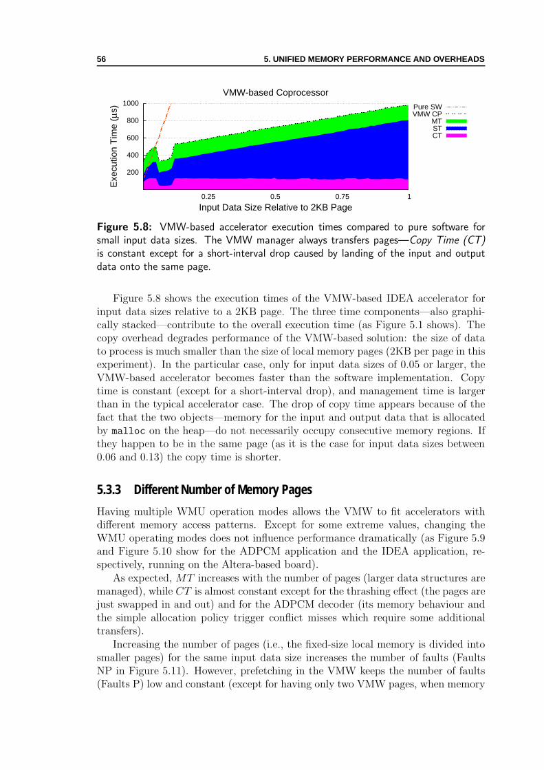
56 5. UNIFIED MEMORY PERFORMANCE AND OVERHEADS
200
400
600
800
1000
0.25 0.5 0.75 1
Exe
cutio
n T
ime
(µs)
Input Data Size Relative to 2KB Page
VMW-based Coprocessor
Pure SW VMW CP
MTSTCT
Figure 5.8: VMW-based accelerator execution times compared to pure software forsmall input data sizes. The VMW manager always transfers pages—Copy Time (CT)is constant except for a short-interval drop caused by landing of the input and outputdata onto the same page.
Figure 5.8 shows the execution times of the VMW-based IDEA accelerator forinput data sizes relative to a 2KB page. The three time components—also graphi-cally stacked—contribute to the overall execution time (as Figure 5.1 shows). Thecopy overhead degrades performance of the VMW-based solution: the size of datato process is much smaller than the size of local memory pages (2KB per page in thisexperiment). In the particular case, only for input data sizes of 0.05 or larger, theVMW-based accelerator becomes faster than the software implementation. Copytime is constant (except for a short-interval drop), and management time is largerthan in the typical accelerator case. The drop of copy time appears because of thefact that the two objects—memory for the input and output data that is allocatedby malloc on the heap—do not necessarily occupy consecutive memory regions. Ifthey happen to be in the same page (as it is the case for input data sizes between0.06 and 0.13) the copy time is shorter.
5.3.3 Different Number of Memory Pages
Having multiple WMU operation modes allows the VMW to fit accelerators withdifferent memory access patterns. Except for some extreme values, changing theWMU operating modes does not influence performance dramatically (as Figure 5.9and Figure 5.10 show for the ADPCM application and the IDEA application, re-spectively, running on the Altera-based board).
As expected, MT increases with the number of pages (larger data structures aremanaged), while CT is almost constant except for the thrashing effect (the pages arejust swapped in and out) and for the ADPCM decoder (its memory behaviour andthe simple allocation policy trigger conflict misses which require some additionaltransfers).
Increasing the number of pages (i.e., the fixed-size local memory is divided intosmaller pages) for the same input data size increases the number of faults (FaultsNP in Figure 5.11). However, prefetching in the VMW keeps the number of faults(Faults P) low and constant (except for having only two VMW pages, when memory

5.3. EXPERIMENTAL RESULTS 57
0
10
20
30
40
50
60
70
80
Number of Local Memory Pages
Exe
cuti
on
Tim
e (m
s)
Pure SWMTHT or STCT
2 4 8 16 32
typical
8820ms
no prefetching
prefetching
Figure 5.9: ADPCM decoder performance for different number of VMW pages (theinput data size is 32KB).
0
10
20
30
40
50
Number of Local Memory Pages
Exe
cuti
on
Tim
e (m
s)
277.7ms 2472ms
2 4 8 16 32
no prefetching
prefetchingtypical
Pure SW
CT
MTHT or ST
Figure 5.10: IDEA execution times for different number of local memory pages (theinput size is 8192 IDEA blocks).
thrashing appears—also visible in Figures 5.9 and 5.10). For smaller page sizes(i.e., local memory contains more pages), manage and copy time intervals becomecomparable to the hardware execution intervals: late faults—less costly than regularones—appear (a fault is “late” when the WMU reports a fault while the missingpage is already being prefetched by the VMW).
5.3.4 Area Overhead
Table 5.1 shows the complexity of the WMU in terms of occupied FPGA resources(logic cells and memory blocks), for the Altera Excalibur device (EPXA1). Theoverhead does not include cost of the local memory (recall Figure 4.2 in Section 4.2)as this memory is necessary even without virtualisation with the WMU. Althoughthe Altera device that we use is the smallest in its family, the WMU area overheadis acceptable (not more than one fifth of the EPXA1 resources are used). The areaoverhead would be practically null, if the WMU were implemented in ASIC, as it is
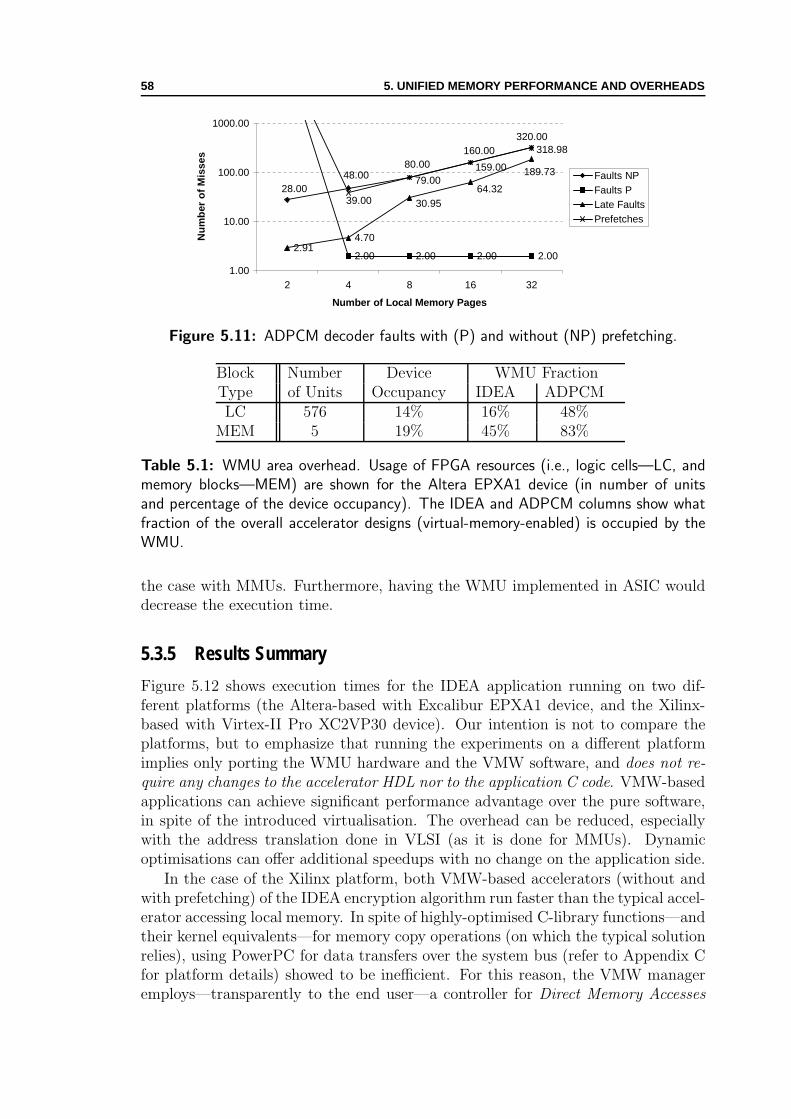
58 5. UNIFIED MEMORY PERFORMANCE AND OVERHEADS
2.00 2.00 2.00 2.002.91
4.70
48.0080.00
160.00320.00
28.0030.95
64.32
189.73
39.00
79.00159.00
318.98
1.00
10.00
100.00
1000.00
2 4 8 16 32
Number of Local Memory Pages
Nu
mb
er o
f M
isse
s
Faults NPFaults PLate FaultsPrefetches
Figure 5.11: ADPCM decoder faults with (P) and without (NP) prefetching.
Block Number Device WMU FractionType of Units Occupancy IDEA ADPCMLC 576 14% 16% 48%
MEM 5 19% 45% 83%
Table 5.1: WMU area overhead. Usage of FPGA resources (i.e., logic cells—LC, andmemory blocks—MEM) are shown for the Altera EPXA1 device (in number of unitsand percentage of the device occupancy). The IDEA and ADPCM columns show whatfraction of the overall accelerator designs (virtual-memory-enabled) is occupied by theWMU.
the case with MMUs. Furthermore, having the WMU implemented in ASIC woulddecrease the execution time.
5.3.5 Results Summary
Figure 5.12 shows execution times for the IDEA application running on two dif-ferent platforms (the Altera-based with Excalibur EPXA1 device, and the Xilinx-based with Virtex-II Pro XC2VP30 device). Our intention is not to compare theplatforms, but to emphasize that running the experiments on a different platformimplies only porting the WMU hardware and the VMW software, and does not re-quire any changes to the accelerator HDL nor to the application C code. VMW-basedapplications can achieve significant performance advantage over the pure software,in spite of the introduced virtualisation. The overhead can be reduced, especiallywith the address translation done in VLSI (as it is done for MMUs). Dynamicoptimisations can offer additional speedups with no change on the application side.
In the case of the Xilinx platform, both VMW-based accelerators (without andwith prefetching) of the IDEA encryption algorithm run faster than the typical accel-erator accessing local memory. In spite of highly-optimised C-library functions—andtheir kernel equivalents—for memory copy operations (on which the typical solutionrelies), using PowerPC for data transfers over the system bus (refer to Appendix Cfor platform details) showed to be inefficient. For this reason, the VMW manageremploys—transparently to the end user—a controller for Direct Memory Accesses

5.3. EXPERIMENTAL RESULTS 59
0
10
20
30
40
50
60
ms
Pure SW
MTS T o r H TCT
IDEA Execution Times for Different Platform Types(128KB Input Data Size)
no prefetching
prefetchingtypical125.17ms277.17ms
Xilinx-PXilinx-NPXilinx
Platform Type
PowerPCAltera-PAltera-NPAlteraARM
Figure 5.12: Two different platforms (Altera Excalibur-based and Xilinx Virtex-II Pro-based) run the same application. Results are shown for pure software (ARM, PowerPC),typical hardware accelerators accessing local memory (Altera, Xilinx), and VMW-basedaccelerators, with no prefetching (Altera-NP, Xilinx-NP) and with prefetching (Altera-P,Xilinx-P) in the VMW.
(DMA) (as Figure 4.2 in Section 4.2 shows). On the other side, the typical solutionhas no such support, thus, it directly suffers from the performance drawback. Ofcourse, the programmer of the typical solution could also use the DMA controller toimprove the performance but, this would require descending to the level of systemprogramming (e.g., to add the appropriate support in the kernel) or using some ofthe existing solutions for user-level DMA (e.g., [80]. In the case of VMW-basedapplications, on the contrary, the application-level programmer can always stick tothe simpler programming interface defined by the VMW manager and, at the sametime, benefit from the system-level support for improved performance.
In the following chapters, we present the VMW and WMU extensions (1) sup-porting transparent execution transfers and hardware callbacks to software (in Chap-ter 6) and (2) enabling multithreaded execution of user software and user hardwarewithin the unified OS process (in Chapter 7). In both chapters, we perform andshow results of additional experiments with cryptography and image processing ap-plications, thus demonstrating unrestricted synthesis of hardware and multithreadedexecution of codesigned applications.

60 5. UNIFIED MEMORY PERFORMANCE AND OVERHEADS
Chapter 6System Supportfor Execution Transfers
If you wish to make an apple pie from scratch, you must first create the universe.—Carl Sagan, Cosmos
THE common virtual address space for user software and user hardware simplifiesthe interfacing and supports advanced programming paradigms for codesigned
applications. Another essential part of the unified OS process is the support for exe-cution transfers from user software to user hardware and vice-versa. In this chapter,we delegate the execution transfer task to the system. Having system software andsystem hardware responsible for the execution transfers furthermore simplifies thesoftware and hardware interfacing. All together with the unified memory for usersoftware and user hardware, it fosters unconstrained partitioning and software-to-hardware code migration. We demonstrate how the unified OS process enablesunrestricted automated synthesis of high-level programming languages to hardware.
6.1 Callbacks to Software
We have discussed in Section 2.3, how programmers may use software wrappers tocall back software and system services on behalf of user hardware. Our unified mem-ory abstraction (introduced in Section 2.5 and implemented in Chapter 4) allows userhardware to use return results of system calls and standard-library functions. Thiswould be either burdensome or even impossible without common virtual-memoryaddress space.
Figure 6.1 and Figure 6.2 illustrate how a hardware accelerator can call backsoftware, even for sophisticated functions such as heap memory allocation. Whenthe accelerator calls back the software, the wrapper invokes the appropriate functionand returns the virtual memory pointer back to the accelerator. Execution of thehardware accelerator is then resumed. When resumed, the accelerator can use thepointer to the allocated memory without any obstacle: using the pointer to accessthe memory initiates the transfer of the accessed data to the local memory of the
61
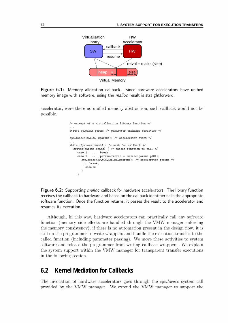
62 6. SYSTEM SUPPORT FOR EXECUTION TRANSFERS
SW
Virtual Memory
HWcallback
resume
heap
VirtualisationLibrary
HWAccelerator
retval = malloc(size)
size
Figure 6.1: Memory allocation callback. Since hardware accelerators have unifiedmemory image with software, using the malloc result is straightforward.
accelerator; were there no unified memory abstraction, such callback would not bepossible.
/* excerpt of a virtualisation library function */
...
struct cp param param; /* parameter exchange structure */
...
sys hwacc (HW ACC, ¶ms); /* accelerator start */
...
while (!params.hwret) { /* wait for callback */
switch(params.cback) { /* choose function to call */
case 1: ... break;
case 2: ... params.retval = malloc (params.p[0]);
sys hwacc (HW ACC RESUME,¶ms); /* accelerator resume */
... break;
case n:
}}
Figure 6.2: Supporting malloc callback for hardware accelerators. The library functionreceives the callback to hardware and based on the callback identifier calls the appropriatesoftware function. Once the function returns, it passes the result to the accelerator andresumes its execution.
Although, in this way, hardware accelerators can practically call any softwarefunction (memory side effects are handled through the VMW manager enforcingthe memory consistency), if there is no automation present in the design flow, it isstill on the programmer to write wrappers and handle the execution transfer to thecalled function (including parameter passing). We move these activities to systemsoftware and release the programmer from writing callback wrappers. We explainthe system support within the VMW manager for transparent transfer executionsin the following section.
6.2 Kernel Mediation for Callbacks
The invocation of hardware accelerators goes through the sys hwacc system callprovided by the VMW manager. We extend the VMW manager to support the

6.2. KERNEL MEDIATION FOR CALLBACKS 63
execution transfer in both directions (i.e., we also support user hardware calling backuser software). The execution transfer goes through the OS kernel. We implementthe Application Binary Interface (ABI) for the particular host CPU within theVMW manager. An ABI [9, 125, 134] defines the calling convention (i.e., callingsequence—how function arguments are passed to callees and how return values areretrieved by callers) at the binary machine-instruction level for a CPU family. TheABI also describes execution transfers from applications to the OS or to libraries.It is different from an Application Programming Interface (API). While an APIguarantees the source code portability by defining the interface between source codeand the OS and libraries, an ABI guaranties integrating the object code (compiledsource) without changes on systems using a compatible ABI. A high-level languagecompiler (more precisely its back-end) implements the ABI for a particular platform.
Calling the sys hwacc system call from a C program ensures, after compilation,compliance to the target ABI. To achieve seamless integration of software and hard-ware, we also delegate such responsibility to hardware; calling back software froma hardware accelerator requires hardware designers (or a synthesiser—a compilerequivalent on the hardware side) to follow the given ABI. The same would be thecase if we had a programmer writing parts of the application code in assembler; in-tegrating assembly routines with a high-level language program demands followingthe ABI rules. Writing the hardware accelerator code in a hardware description lan-guage is equivalent to writing in an assembler. If a synthesiser is used, the designerdelegates the ABI interfacing tasks to the automated generation of ABI interfaces.Having the unified memory between software and hardware allows the designer orthe synthesiser to use the user-space stack for calling sequence and parameter pass-ing. As it is the practice with CPUs [56] to avoid using the stack (for invokingfunctions with small number of parameters) by using general purpose registers orregisters windows, we design the WMU with an exchange register file (as Figure 4.2shows). We give more details on using the register file for parameter passing inAppendices A and B.
Apart from hardware accelerators complying to the ABI interface when callingback software, we need the VMW manager involvement in the execution transfer:a hardware accelerator cannot just jump in the user software or system call codedirectly; the VMW manager performs this task instead. We use a mechanism similarto UNIX signal handling [76, 117] to implement the task of execution transfer fromhardware to software. Figure 6.3 shows the sequence of the events to call backsoftware from hardware.
At the system-call entry, the CPU switches the execution mode from the usermode to a privileged one. This also means changing the memory address space—user-space memory is no more directly accessible by the kernel, but only throughfew special memory-access functions [12, 19]. Changing the memory address spaceimposes using a different stack when running in the kernel mode; each process has auser stack and a kernel stack for user-space and kernel-space executions, respectively.The first frame allocated on the kernel stack contains the state of all CPU registersvisible to the programmer. In this way, before returning from the system call, thekernel can recover the original CPU state.
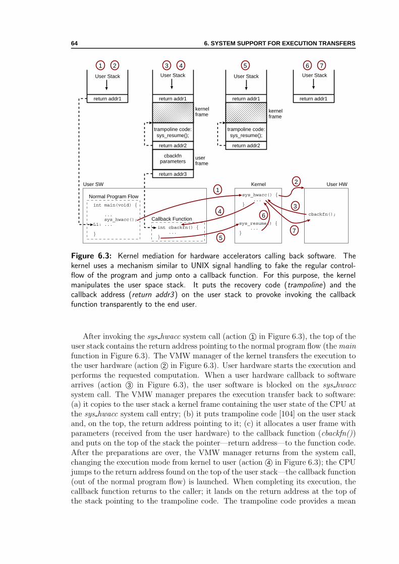
64 6. SYSTEM SUPPORT FOR EXECUTION TRANSFERS
return addr1 return addr1
kernelframe
trampoline code:
return addr2
userframe
cbackfnparameters
return addr3
sys_resume();
return addr1
kernel frame
return addr1
trampoline code:
return addr2
sys_resume();
int main(void) {
... sys_hwacc();L1: ...
}
Normal Program Flow
int cbackfn() { ...}
Callback Function
User SW Kernel User HW
sys_hwacc() { ...}
sys_resume() { ...}
cbackfn();
12
34
5
6
1 2 3 4 5
7
6 7
User Stack User Stack User Stack User Stack
Figure 6.3: Kernel mediation for hardware accelerators calling back software. Thekernel uses a mechanism similar to UNIX signal handling to fake the regular control-flow of the program and jump onto a callback function. For this purpose, the kernelmanipulates the user space stack. It puts the recovery code (trampoline) and thecallback address (return addr3) on the user stack to provoke invoking the callbackfunction transparently to the end user.
After invoking the sys hwacc system call (action ©1 in Figure 6.3), the top of theuser stack contains the return address pointing to the normal program flow (the mainfunction in Figure 6.3). The VMW manager of the kernel transfers the execution tothe user hardware (action ©2 in Figure 6.3). User hardware starts the execution andperforms the requested computation. When a user hardware callback to softwarearrives (action ©3 in Figure 6.3), the user software is blocked on the sys hwaccsystem call. The VMW manager prepares the execution transfer back to software:(a) it copies to the user stack a kernel frame containing the user state of the CPU atthe sys hwacc system call entry; (b) it puts trampoline code [104] on the user stackand, on the top, the return address pointing to it; (c) it allocates a user frame withparameters (received from the user hardware) to the callback function (cbackfn())and puts on the top of the stack the pointer—return address—to the function code.After the preparations are over, the VMW manager returns from the system call,changing the execution mode from kernel to user (action ©4 in Figure 6.3); the CPUjumps to the return address found on the top of the user stack—the callback function(out of the normal program flow) is launched. When completing its execution, thecallback function returns to the caller; it lands on the return address at the top ofthe stack pointing to the trampoline code. The trampoline code provides a mean
6.3. ENABLING UNRESTRICTED AUTOMATED SYNTHESIS 65
to resume the kernel execution of the VMW manager by calling a special systemcall sys resume. The callback function returns to the trampoline code which, inturn, resumes the kernel execution (action ©5 in Figure 6.3). The VMW manageris again in charge; it first copies the kernel frame back to the kernel stack (action©6 in Figure 6.3); then, the VMW manager passes the return value of the callbackfunction and resumes the execution of the user hardware (action ©7 in Figure 6.3).In this way, the transparent callback sequence is over and the user hardware cancontinue its computation.
The accelerator execution continues toward the next callback to software or thefinal completion and return from the sys hwacc call (to the regular return address—labeled with L1 in Figure 6.3—in the program flow). The programmer does notneed any more to write wrapper code supporting the callbacks (in contrast to Fig-ure 2.8 and Figure 6.2): it is now the responsibility of the VMW manager. Theunified OS process for codesigned applications now becomes complete having thesupport for virtual memory abstraction and arbitrary execution transfers betweenheterogeneous application parts. Section 6.3 showcases how the unified OS processenables the unrestricted automated synthesis of hardware accelerators from high-level programming languages.
Some Implications. Having virtual-memory-enabled hardware acceleratorsand the execution transfers supported by the system, we can imagine hardware-centric applications (i.e., applications with its main execution thread in user hard-ware going back to software just for the system and library calls). Such applicationslargely use the hardwired logic and sparsely the CPU——at least at the user level.There could be many possible applications. One could imagine a video monitoringsystem with a video encoding engine and a detector, implemented completely inhardware but connected to a standard computer: a particular event triggers record-ing; in turn, the accelerator opens a regular file through the appropriate system callto save the recording. Remembering Figure 1.4 from the introductory chapter, ourextensions have made such a system true: user hardware and user software are nowpeers, any of them can dominate in codesigned applications.
6.3 Enabling Unrestricted Automated Synthesis
Abstract language constructs and concepts bring major difficulties for synthesisof program parts written in high-level programming languages to hardware. Ourgoal is to attain unconstrained application partitioning and to be able to synthesisehardware without any restriction on the input program (unrestricted synthesis). Themajor problems are the following: (1) in a general case, memory access behaviourof a program is not known at synthesis time, thus, it is impossible to schedulememory transfers—servicing the accelerator accesses—in advance; (2) not all partsof the program can be efficiently implemented in hardware. In case a program partto be synthesised to hardware uses an aliased pointer [11], allocates memory onthe heap, calls another function, or happens to call itself recursively, its mappingbecomes more complex. Either additional analyses are required (e.g., either aliasinganalysis [100] or memory partitioning [106]), or the synthesis is to be abandoned.

66 6. SYSTEM SUPPORT FOR EXECUTION TRANSFERS
LocalMemory
HWAccel.
FPGA PhysicalAddress
CPU
Programmer-definedMemory Partitioning
(a) Programmer-initiated Memory Transfers
HWAccel.
FPGA
WMU
Virtual Memory
VirtualAddress
PhysicalAddress
CPU
VMW Manager
VMW-definedPartitioning (Pages)
LocalMemory
(b) Accelerator-initiated Memory Transfers
Figure 6.4: Handling memory transfers for hardware accelerators: explicit programmer-scheduled (a) and transparent accelerator-initiated memory transfers (b). Programmer-initiated memory transfers require explicit knowledge on the memory access pattern ofthe accelerator. In the case where the accelerator initiates memory transfers, there is nosuch requirement.
The unified OS process for codesigned applications enables unrestricted auto-mated synthesis from high-level programming languages. The system layer responsi-ble for providing seamless interfacing and execution transfers fosters mobility of usercode, be it from software to hardware or vice-versa. We apply our approach [119]within a virtual execution environment, such as Java Virtual Machine (JVM), toshow the synthesis-related advantages of the unified OS process.
The abstraction provided by the unified OS process offers a solution to thepreviously-stated synthesis problems. Our primary concern is to support the un-restricted synthesis and not to explore the challenges of doing it efficiently—it isa well-known research area [35]. As Chapter 4 shows, the VMW manager allowsdynamic handling of hardware-accelerator memory accesses. Whatever is the mem-ory access pattern of the user hardware, the manager will ensure that the correctnonstale data is available to the accelerator. In contrast to the typical architectureswhere the programmer explicitly transfers the data to be processed, the VMW per-forms transparent accelerator-initiated handling of memory accesses (as Figure 6.4shows) at runtime. Whatever is the memory access pattern, neither programmers

6.3. ENABLING UNRESTRICTED AUTOMATED SYNTHESIS 67
nor hardware designers need to know anything about. Beside arbitrary memoryaccesses, in Section 6.2 we have shown how the VMW manager handles executiontransfers and hardware callbacks to arbitrary software functions. Synthesised accel-erators running in the unified OS process immediately benefit from dynamic optimi-sations in the system software and system hardware (as Section 4.4 and Section 5.3demonstrate).
6.3.1 Synthesis Flow
The unified OS process facilitates unrestricted automated synthesis [39, 122]. Shar-ing the same virtual memory, dynamically handling accelerator memory accesses,and having a standardised possibility to callback software enables synthesis of anyJava bytecode method to reconfigurable hardware. Even sophisticated high-levellanguage concepts such as object creation (recall the malloc example in Section 6.1),method invocation, and recursion, can be initiated by hardware and handled by theJVM. The presence of the VMW manager makes software to hardware migrationeasier. The migration could even happen dynamically, at runtime. Then, however,logic synthesis and place and route runtime become a major challenge [79]—theseissues are beyond the scope of this thesis.
Java BytecodeConfiguration File
Graph creator:CFG, DFG,Sequencing
Binding &Scheduling
CodeGenerator
VHDLresources
Compilation
EDA SynthesiserPlace & Route
Synthesis (Vendor Specific)
XML Descriptor FileFPGA Config File
Results
Resource InterconnectionFinite State Machine
Figure 6.5: Automated unrestricted synthesis flow. The flow consists of typical high-level synthesis passes and the FPGA back end. An intermediate output of the compilationpart is the VHDL description of the input Java method. The final outputs are the FPGAconfiguration file and the XML file containing the information on loading the modifiedJava class.
Figure 6.5 shows our basic synthesis flow (named Compilation in the figure) [39].Its inputs are Java bytecode of critical methods and a compiler configuration file.The flow consists of typical high-level synthesis phases [35] such as: (1) sequencinggraph construction; (2) resource binding and operation scheduling; (3) code con-struction. The generated VHDL code describes the interconnections between theresources and the finite state machines resulting from the scheduling step. An EDA
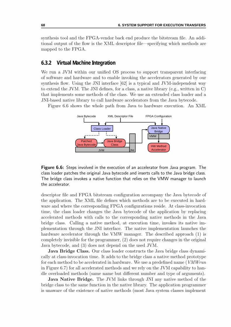
68 6. SYSTEM SUPPORT FOR EXECUTION TRANSFERS
synthesis tool and the FPGA-vendor back end produce the bitstream file. An addi-tional output of the flow is the XML descriptor file—specifying which methods aremapped to the FPGA.
6.3.2 Virtual Machine Integration
We run a JVM within our unified OS process to support transparent interfacingof software and hardware and to enable invoking the accelerators generated by oursynthesis flow. Using the JNI interface [62] is a typical and JVM-independent wayto extend the JVM. The JNI defines, for a class, a native library (e.g., written in C)that implements some methods of the class. We use an extended class loader and aJNI-based native library to call hardware accelerators from the Java bytecode.
Figure 6.6 shows the whole path from Java to hardware execution. An XML
Java Bytecode XML Descriptor File FPGA Configuration
Class Loader
PatchedJava Bytecode
Java BridgeClass
Java NativeBridge
JVM JNI
VMW
HW MethodAccelerator
Figure 6.6: Steps involved in the execution of an accelerator from Java program. Theclass loader patches the original Java bytecode and inserts calls to the Java bridge class.The bridge class invokes a native function that relies on the VMW manager to launchthe accelerator.
descriptor file and FPGA bitstream configuration accompany the Java bytecode ofthe application. The XML file defines which methods are to be executed in hard-ware and where the corresponding FPGA configurations reside. At class-invocationtime, the class loader changes the Java bytecode of the application by replacingaccelerated methods with calls to the corresponding native methods in the Javabridge class. Calling a native method, at execution time, invokes its native im-plementation through the JNI interface. The native implementation launches thehardware accelerator through the VMW manager. The described approach (1) iscompletely invisible for the programmer, (2) does not require changes in the originalJava bytecode, and (3) does not depend on the used JVM.
Java Bridge Class. Our class loader constructs the Java bridge class dynami-cally at class-invocation time. It adds to the bridge class a native method prototypefor each method to be accelerated in hardware. We use a predefined name (VMWrunin Figure 6.7) for all accelerated methods and we rely on the JVM capability to han-dle overloaded methods (same name but different number and type of arguments).
Java Native Bridge. The JVM links through JNI any native method of thebridge class to the same function in the native library. The application programmeris unaware of the existence of native methods (most Java system classes implement

6.3. ENABLING UNRESTRICTED AUTOMATED SYNTHESIS 69
/* IDEAEngine Java class */
void encrypt (
byte[] data in,
byte[] data out,
int[] key
)
/* Bridge Java class */
void VMWrun (
int methodId,
byte[] data in,
byte[] data out,
int[] key
)
/* Bridge native library */
void VMWrun (
int methodId,
...) {sys hwacc (HW ACC, ¶m);
}
(a) (b) (c)
Figure 6.7: Invoking hardware accelerators from a Java application: the original method(a) is replaced with the call to a bridge class (b) which calls the native library (c) startingthe accelerator.
their methods as native) and hardware accelerators. The native bridge code isresponsible for (1) configuring the FPGA for the first use of an accelerator, (2)invoking the accelerator through sys hwacc call, and (3) defining possible hardware-callback functions.
Parameter passing. The native implementation must handle different accel-erators, neither their parameter type nor their number is known at compile time.After using the method identifier to read the number of parameters and their typesfrom the XML descriptor file, it retrieves the parameters thanks to the variablearguments feature of C.
Accessing JVM objects. The native implementation has to interpret correctlythe type of parameters received from the JVM. If necessary, conversions are doneusing an appropriate JNI function. For example, obtaining a native pointer for anobject reference—there are no pointers in Java—requires calling the JNI function.This discipline also maintains memory consistency, since the garbage collector doesnot move the acquired objects until their release.
Accelerator Callback. To perform a callback, an accelerator uses the execu-tion transfer sequence of the VMW (described in Section 6.2) to call the appropriatefunction of the JNI interface. The callback feature allows performing high level op-erations (e.g., object allocation, synchronisation, virtual method invocation) thatrequire support of the JVM. This is essential when it comes to unrestricted auto-mated synthesis from Java bytecode to hardware. Even if calling back software maybe costly, the feature supports constructing hyperblocks [25] and allows mappinglarger code sections from software to hardware. The expectation is that the call-backs are not so frequent in computation-intensive methods. When applicable, ourflow also uses method inlining, to avoid unnecessary callbacks.
6.3.3 Experiments
The measurement results refer to the development board based on the Altera Excal-ibur device (refer to Appendix C). Kaffe [64], an open source virtual machine, runsin the JiT (Just-in-Time compilation) mode on top of a unified GNU/Linux processfor codesigned applications. We do not measure the time for FPGA configuration;although this time may be significant when compared to a single program execution,we assume the accelerated program is run multiple times for a longer period of time;in this case the configuration time becomes irrelevant.
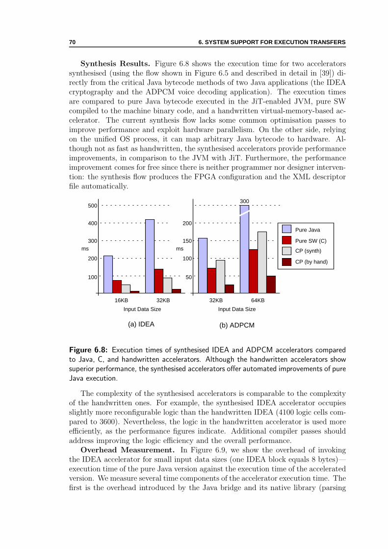
70 6. SYSTEM SUPPORT FOR EXECUTION TRANSFERS
Synthesis Results. Figure 6.8 shows the execution time for two acceleratorssynthesised (using the flow shown in Figure 6.5 and described in detail in [39]) di-rectly from the critical Java bytecode methods of two Java applications (the IDEAcryptography and the ADPCM voice decoding application). The execution timesare compared to pure Java bytecode executed in the JiT-enabled JVM, pure SWcompiled to the machine binary code, and a handwritten virtual-memory-based ac-celerator. The current synthesis flow lacks some common optimisation passes toimprove performance and exploit hardware parallelism. On the other side, relyingon the unified OS process, it can map arbitrary Java bytecode to hardware. Al-though not as fast as handwritten, the synthesised accelerators provide performanceimprovements, in comparison to the JVM with JiT. Furthermore, the performanceimprovement comes for free since there is neither programmer nor designer interven-tion: the synthesis flow produces the FPGA configuration and the XML descriptorfile automatically.
16KB
(a) IDEA
100
200
300
400
500
(b) ADPCM
Input Data Size
ms
Pure Java
Pure SW (C)
CP (synth)
32KB 32KB
50
100
150
200
Input Data Size
ms
64KB
CP (by hand)
300
Figure 6.8: Execution times of synthesised IDEA and ADPCM accelerators comparedto Java, C, and handwritten accelerators. Although the handwritten accelerators showsuperior performance, the synthesised accelerators offer automated improvements of pureJava execution.
The complexity of the synthesised accelerators is comparable to the complexityof the handwritten ones. For example, the synthesised IDEA accelerator occupiesslightly more reconfigurable logic than the handwritten IDEA (4100 logic cells com-pared to 3600). Nevertheless, the logic in the handwritten accelerator is used moreefficiently, as the performance figures indicate. Additional compiler passes shouldaddress improving the logic efficiency and the overall performance.
Overhead Measurement. In Figure 6.9, we show the overhead of invokingthe IDEA accelerator for small input data sizes (one IDEA block equals 8 bytes)—execution time of the pure Java version against the execution time of the acceleratedversion. We measure several time components of the accelerator execution time. Thefirst is the overhead introduced by the Java bridge and its native library (parsing

6.3. ENABLING UNRESTRICTED AUTOMATED SYNTHESIS 71
the XML descriptor file and creating bridge class dynamically). Two thirds of theoverhead are coming from the XML configuration file reading; by optimising thisoperation, the overhead could potentially go below 200µs. The other observabletime components relate to the VMW interface (recall Manage time, Copy time,Hardware time from Section 5.2). The sum of the manage time and the copy timeis constant, since for any data input size in the graph, only one page of memoryis used (the page size is 2KB). Only the hardware time, which is real computationtime, is affected by input size.
8B
IDEA
200
400
Input Data Size
µs
Pure Java
16B
600
800
32B 64B
Hardware Time
Copy Time
Manage Time
Bridge Overhead
Figure 6.9: Invocation overhead for small data sizes. IDEA encryption of 8 bytesto 64 bytes (one to eight 64-bit blocks) of input data. The Java bridge overhead isconsiderable.
For the two first data input sizes (8 bytes and 16 bytes), the time is almost thesame. In fact, this is due to the way that the IDEA accelerator works (as the graphsfrom Appendix E clarify): it has a three-stage pipeline that encrypts 3 blocks at atime; thus, the time required to compute 1, 2, or 3 blocks (8, 16, or 24 bytes) ismore or less the same. Since the core computation is performed three times, onecan see a difference for encryption of 8 blocks.
For 64 bytes (8 blocks), the accelerator version becomes faster than pure Javasoftware, despite the introduced overhead. The same behaviour, with a differentbreak-even point, is expected for other applications having similar memory accesspatterns. If we recall that the overhead could be reduced (since the current im-plementation is not optimal), the break-even point can move toward even smallerdatasets. What is more important, the total overhead (750µs) becomes negligi-ble for typical input data sizes, especially when one recalls the benefits it brings:transparent and platform-independent acceleration of Java programs.

72 6. SYSTEM SUPPORT FOR EXECUTION TRANSFERS
6.3.4 Summary
The WMU system hardware and the VMW system software enable mapping anyvirtual machine code to hardware and support portability of codesigned applica-tions. Running a JVM and Java applications within the unified OS process allowstransparent use of hardware accelerators to programmers—no change is required inthe application software. Our unrestricted synthesis flow for JVM platforms [39, 61]allows handling high-level language concepts such as object creation and methodinvocation. Further improvements of the flow shall employ typical synthesis optimi-sations and exploit better the available hardware parallelism.

Chapter 7Transparent Software and HardwareMultithreading
As soon as you perceive an object, you draw a line between it and the rest of theworld; you divide the world, artificially, into parts, and you thereby miss the Way.
—Douglas Hofstadter, Godel, Escher, Bach
IN this chapter we discuss the extension of our unified OS process for codesignedapplications to support multithreaded execution of user software and user hard-
ware. Programmers use threads to exploit application parallelism without the costof having multiple processes communicating to each other. Creating threads costsless than creating processes; multiple threads within a user process share the samememory address space and some per-process OS data structures. Using threads canbe fruitful even in uniprocessor systems; before blocking in a system call, a threadcan create another thread that continues the execution; thus, the process does notyield the CPU to another process.
Having unified memory abstraction between user software and user hardware isessential for supporting multithreaded programming paradigms. In the followingsections, we present the extensions to our baseline system shown in Chapter 4 tosupport multithreaded execution. Figure 7.1 shows the architecture we are target-ing for multithreading. Our implementation provides an initial infrastructure forsimultaneous execution of multiple virtual-memory-enabled hardware acceleratorsbut, it is not necessarily the most efficient one. Our goal—in the first place we aretargeting reconfigurable SoCs—is to show feasibility of the unified OS process ex-tensions to support multithreading; for addressing efficiency, scalability, and futureimprovements, the extensive existing literature [95] in this field should be used.
7.1 Extending a Multithreaded Programming Paradigm
In this section, we build a multithreaded programming paradigm for codesignedapplications based on the standard multithreaded programming model—POSIXthreads [88]. Relying on the POSIX thread library and the OS support for inter-
73
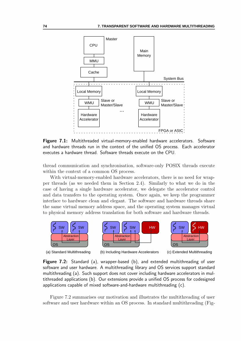
74 7. TRANSPARENT SOFTWARE AND HARDWARE MULTITHREADING
CPU
MMU
Cache
System Bus
MainMemory
Slave orMaster/Slave
Master
FPGA or ASIC
HardwareAccelerator
WMU
Local Memory
...Hardware
Accelerator
WMU
Local Memory
Slave orMaster/Slave
Figure 7.1: Multithreaded virtual-memory-enabled hardware accelerators. Softwareand hardware threads run in the context of the unified OS process. Each acceleratorexecutes a hardware thread. Software threads execute on the CPU.
thread communication and synchronisation, software-only POSIX threads executewithin the context of a common OS process.
With virtual-memory-enabled hardware accelerators, there is no need for wrap-per threads (as we needed them in Section 2.4). Similarly to what we do in thecase of having a single hardware accelerator, we delegate the accelerator controland data transfers to the operating system. Once again, we keep the programmerinterface to hardware clean and elegant. The software and hardware threads sharethe same virtual memory address space, and the operating system manages virtualto physical memory address translation for both software and hardware threads.
OS
AbstractionLayer
(a) Standard Multithreading (b) Including Hardware Accelerators (c) Extended Multithreading
SW SW HW
OS
AbstractionLayer
SW SW
OS
AbstractionLayer
SW HW
Figure 7.2: Standard (a), wrapper-based (b), and extended multithreading of usersoftware and user hardware. A multithreading library and OS services support standardmultithreading (a). Such support does not cover including hardware accelerators in mul-tithreaded applications (b). Our extensions provide a unified OS process for codesignedapplications capable of mixed software-and-hardware multithreading (c).
Figure 7.2 summarises our motivation and illustrates the multithreading of usersoftware and user hardware within an OS process. In standard multithreading (Fig-

7.2. SUPPORT FOR EXTENDED MULTITHREADING 75
ure 7.2a), simultaneous execution of software threads is provided by an abstractionlayer usually consisting of thread libraries (e.g., POSIX threads) supported by OSservices. Nevertheless, the existing abstraction layers (Figure 7.2b) do not sup-port integrating hardware accelerators with software, and wrapper threads (as Fig-ure 2.9b in Section 2.4 shows) are typically used to perform accelerator control anddata transfers. If the layer is extended (Figure 7.2c) to support hardware threads(i.e., to enable communication, synchronisation and sharing of virtual memory ad-dress space), programming is improved and brought to the level of software-onlyapplications: programmers and hardware designers can seamlessly integrate soft-ware and hardware application parts. In the following section we explain how thesystem layer can provide the multithreaded programming paradigm for codesignedapplications.
7.2 Support for Extended Multithreading
To achieve the transparent multithreading of user software and user hardware withinan OS process (as presented in Figure 7.1), we need to extend (1) the existingWMU for supporting the coherence of the WMU local memories, and (2) the VMWmanager for steering multiple WMUs and ensuring memory consistency.
7.2.1 WMU Extensions
Having multiple virtual-memory-enabled hardware accelerators that run in parallelaccessing their local memories may violate data integrity. To enable the hardwareaccelerators to share the coherent memory and to enforce strict memory consistency,we extend the basic WMUs with a simple, invalidation-based, mixed hardware-and-software coherency protocol [95].
Figure 7.3 shows multiple WMUs connected to an internal, custom coherencebus, separated from the system one. An arbiter accessible and controllable by theOS through the system bus is also connected to the coherence bus. Each WMUkeeps track of states for the pages residing in the local memory and snoops on thecoherence bus (the protocol diagram is shown in Figure 7.4). Bus-incoming stimuli,OS events, or hardware accelerator actions (written in italics in Figure 7.4) initiatestate transitions. Either the OS or the WMUs are responsible for the transitions. Astate transition for a particular WMU is sometimes followed by a bus action—thisis the outcome (written in boldface) of the transition. The Copy In and WriteBack actions happen on the system bus: (1) Copy In means that a missing page isbrought to the local memory either from the main memory or from the local memoryof another hardware accelerator; (2) Write Back means that a dirty page is copiedback to the main memory. The Invalidate action happens on the consistency bus.Prior to writing to a shared page, the originating WMU sends Invalidate stimulusto other WMUs sharing the page.
The protocol divides the responsibility for the actions between software (OS) andhardware (WMU). Prior to a write access to a shared page, the originating WMUhas first to obtain access to the bus from the arbiter. After informing other WMUs
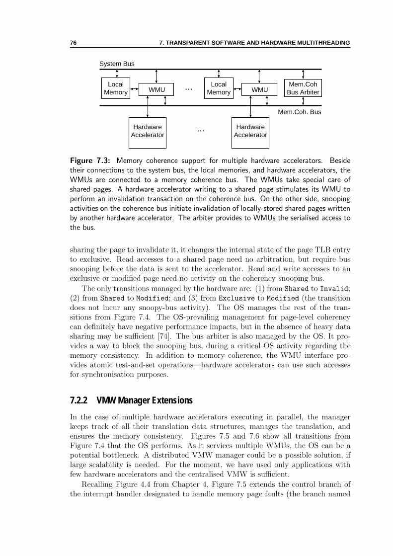
76 7. TRANSPARENT SOFTWARE AND HARDWARE MULTITHREADING
System Bus
HardwareAccelerator
WMU ...
HardwareAccelerator
WMUMem.Coh
Bus ArbiterLocal
MemoryLocal
Memory
...
Mem.Coh. Bus
Figure 7.3: Memory coherence support for multiple hardware accelerators. Besidetheir connections to the system bus, the local memories, and hardware accelerators, theWMUs are connected to a memory coherence bus. The WMUs take special care ofshared pages. A hardware accelerator writing to a shared page stimulates its WMU toperform an invalidation transaction on the coherence bus. On the other side, snoopingactivities on the coherence bus initiate invalidation of locally-stored shared pages writtenby another hardware accelerator. The arbiter provides to WMUs the serialised access tothe bus.
sharing the page to invalidate it, it changes the internal state of the page TLB entryto exclusive. Read accesses to a shared page need no arbitration, but require bussnooping before the data is sent to the accelerator. Read and write accesses to anexclusive or modified page need no activity on the coherency snooping bus.
The only transitions managed by the hardware are: (1) from Shared to Invalid;(2) from Shared to Modified; and (3) from Exclusive to Modified (the transitiondoes not incur any snoopy-bus activity). The OS manages the rest of the tran-sitions from Figure 7.4. The OS-prevailing management for page-level coherencycan definitely have negative performance impacts, but in the absence of heavy datasharing may be sufficient [74]. The bus arbiter is also managed by the OS. It pro-vides a way to block the snooping bus, during a critical OS activity regarding thememory consistency. In addition to memory coherence, the WMU interface pro-vides atomic test-and-set operations—hardware accelerators can use such accessesfor synchronisation purposes.
7.2.2 VMW Manager Extensions
In the case of multiple hardware accelerators executing in parallel, the managerkeeps track of all their translation data structures, manages the translation, andensures the memory consistency. Figures 7.5 and 7.6 show all transitions fromFigure 7.4 that the OS performs. As it services multiple WMUs, the OS can be apotential bottleneck. A distributed VMW manager could be a possible solution, iflarge scalability is needed. For the moment, we have used only applications withfew hardware accelerators and the centralised VMW is sufficient.
Recalling Figure 4.4 from Chapter 4, Figure 7.5 extends the control branch ofthe interrupt handler designated to handle memory page faults (the branch named
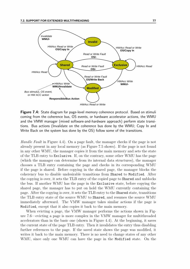
7.2. SUPPORT FOR EXTENDED MULTITHREADING 77
Invalid
Exclusive
Modified
Shared
OS/Copy In
Invalidate
OS/-
OS/-
HWAcc Read or Write
WMU/-HWAcc Write
HWAcc Read
HWAcc Read or Write
Read or Write Fault
Read or Write Fault
HWAcc Read
WMU/InvalidateHWAcc Write
OS/Write BackRead or Write Fault
OS/Copy InHWAcc Read or Write
WMU/-
Bus stimulus, OS event,or HW ACC action
Responsible/Bus Action
Figure 7.4: State diagram for page-level memory coherence protocol. Based on stimulicoming from the coherence bus, OS events, or hardware accelerator actions, the WMUand the VMW manager (mixed software-and-hardware approach) perform state transi-tions. Bus actions (Invalidate on the coherence bus done by the WMU; Copy In andWrite Back on the system bus done by the OS) follow some of the transitions.
Handle Fault in Figure 4.4). On a page fault, the manager checks if the page is notalready present in any local memory (as Figure 7.5 shows). If the page is not foundin any other WMU, the manager copies it from the main memory and sets the stateof the TLB entry to Exclusive. If, on the contrary, some other WMU has the page(which the manager can determine from its internal data structures), the managerchooses a TLB entry containing the page and checks in its corresponding WMUif the page is shared. Before copying in the shared page, the manager blocks thecoherency bus to disable undesirable transitions from Shared to Modified. Afterthe copying is over, it sets the TLB entry of the copied page to Shared and unblocksthe bus. If another WMU has the page in the Exclusive state, before copying theshared page, the manager has to put on hold the WMU currently containing thepage. After the copying is over, it sets the TLB entry to the Shared state, transitionsthe TLB entry state of the source WMU to Shared, and resumes the source WMUimmediately afterward. The VMW manager takes similar actions if the page isModified, except that it also copies it back to the main memory.
When evicting a page, the VMW manager performs the actions shown in Fig-ure 7.6—evicting a page is more complex in the VMW manager for multithreadedaccelerators than in the basic one (shown in Figure 4.4). At the beginning, it savesthe current state of the page TLB entry. Then it invalidates the entry thus disablingfurther references to the page. If the saved state shows the page was modified, itwrites it back to the main memory. There is no need to change states of any otherWMU, since only one WMU can have the page in the Modified state. On the

78 7. TRANSPARENT SOFTWARE AND HARDWARE MULTITHREADING
Copy In the page;Set the TLB entry to
EXCLUSIVE
Handle Fault
Another WMUhas the page?
yesno
Get a TLB entrypointing to the page
Is the pageSHARED?
noyes
Block Arbiter;Copy In the page;
Set the TLB entry to SHARED;Unblock Arbiter
Is the pageEXCLUSIVE?
no
yes
Block the WMU;Write Back
MODIFIED page
Block the WMU;Copy In the page;
Set both TLB entries to SHARED;Unblock the WMU
Copy In the page;Set both TLB entries to SHARED;
Unblock the WMU
Go to sleep
Figure 7.5: VMW manager actions on a memory fault of a multithreaded accelerator.In contrast to the basic VMW manager, there are multiple checks to be done.
contrary, if the page is in some other state than Modified, some additional checksare required (as Figure 7.6 shows) for performing possible state transitions in otherWMUs.
Another feature of the VMW manager enables consistent memory between userhardware and user software (since they can execute in parallel). If user softwaretries accessing a page currently present in one of the local memories, the OS blocksthe process and puts it on a wait queue. Writing back the modified page andinvalidating the appropriate TLB entry initiates the wake up of all sleeping softwarethreads waiting on the page. Although costly (especially because false sharing atthe page-level granularity can easily degrade performance), the approach ensuresbasic memory consistency for applications with no heavy memory sharing. Thesolution is in favour of user hardware. To overcome this, the VMW also providesrelaxed models that avoid blocking but expose the synchronisation tasks to theprogrammer [52].
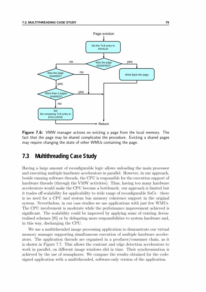
7.3. MULTITHREADING CASE STUDY 79
Handle Fault
Was the pageMODIFIED?
yesno
Write Back the pageno
Set the TLB entry toINVALID
Page eviction
Was the pageSHARED?
yes
More than 2 pagesSHARED?
no
Setthe remaining TLB entry to
EXCLUSIVE
yes
Return
Figure 7.6: VMW manager actions on evicting a page from the local memory. Thefact that the page may be shared complicates the procedure. Evicting a shared pagesmay require changing the state of other WMUs containing the page.
7.3 Multithreading Case Study
Having a large amount of reconfigurable logic allows unloading the main processorand executing multiple hardware accelerators in parallel. However, in our approach,beside running software threads, the CPU is responsible for the execution support ofhardware threads (through the VMW activities). Thus, having too many hardwareaccelerators would make the CPU become a bottleneck: our approach is limited butit trades off scalability for applicability to wide range of reconfigurable SoCs—thereis no need for a CPU and system bus memory coherence support in the originalsystem. Nevertheless, in our case studies we use applications with just few WMUs.The CPU involvement is moderate while the performance improvement achieved issignificant. The scalability could be improved by applying some of existing decen-tralised schemes [95] or by delegating more responsibilities to system hardware and,in this way, discharging the CPU.
We use a multithreaded image processing application to demonstrate our virtualmemory manager supporting simultaneous execution of multiple hardware acceler-ators. The application threads are organised in a producer/consumer chain, as itis shown in Figure 7.7. This allows the contrast and edge detection accelerators towork in parallel, on different image windows slid in time. Their synchronisation isachieved by the use of semaphores. We compare the results obtained for the code-signed application with a multithreaded, software-only version of the application.

80 7. TRANSPARENT SOFTWARE AND HARDWARE MULTITHREADING
HWSW
Virtual Memory
CameraCapture
ContrastEngine
HW
EdgeEngine
Figure 7.7: Producer/consumer chain of threads for edge detection.
7.3.1 Multithreaded Execution
Figure 7.8 and Figure 7.9 show executions times of two image processing hardwareaccelerators (contrast enhancement and edge detection [112]) processing a window(region of interest) within an image (as Figure 5.2 shows). Both accelerators aredesigned and run on the Xilinx ML310 platform (refer to Appendix C for moredetails about the platform). We show their design and implementation details inAppendix D. To study their characteristics, we first consider the accelerators run-ning separately. Later on, we put them together in the multithreaded applicationillustrated in Figure 7.7. The typical codesigned applications use hardware ac-celerators directly accessing the main memory (as explained in Figure 2.5 and inFigure 2.6b). In the case of virtual-memory-based hardware accelerators, we usethe local memory of 64KB organised into 8 pages (the bar in the middle for allprocessing window sizes) or 16 pages (two leftmost bars for all processing windowsizes). The OS module uses DMA to transfer the pages to the local memory. Inthis way, the end user benefits from the improved performance but is completelyscreened of the enhanced system-level support.
The typical accelerator in Figure 7.8 does not implement burst accesses to thememory which affects its performance. Despite the page-level granularity overhead,the virtual-memory-enabled accelerators outperform the typical solution. More im-portantly, the benefit comes for free for the hardware designer: there is no need toimplement and manage memory transfer bursts.
The typical accelerator in Figure 7.9 implements burst accesses to the memoryand local caching of the transferred data. It is significantly faster than the virtual-memory-enabled accelerator for the smallest window size but, for larger windowsizes, the two approaches get close performance figures; yet, the WMU memoryinterface is much simpler (no burst and no pipelining support). It is a simpler wayfor a designer (thanks to shifting the interfacing and data transfer burden to thesystem level) to get results comparable with typical approaches.
We put the contrast enhancement and edge detection engines together in the mul-tithreaded application from Figure 7.7, consisting of one software and two hardwarethreads. We use the multithreaded image processing application to demonstrate our

7.3. MULTITHREADING CASE STUDY 81
0
10
20
30
40
50
60
70
80
160x120 320x240 512x512
ms
Window Size
Contrast Enhancement in SW and HW
138.3ms
Pure SWTypical HW
MTSTCT }Virtual HW
Local memory 8 pages(no prefetching)
Local memory 16 pages(no prefetching)
Local memory 16 pages(with prefetching)
Figure 7.8: Execution times of contrast-enhancement application implemented in puresoftware, typical hardware, and virtual memory-enabled hardware.
virtual memory manager supporting simultaneous execution of multiple hardwareaccelerators. We set up the application threads (shown in Figure 7.7) in a produc-er/consumer chain that allows the contrast and edge detection accelerators to workin parallel, on different image windows slid in time. We compare the results ob-tained for software-only version of the application and the codesigned applicationswith typical or virtual-memory-enabled accelerators.
Apart from the significant performance improvement obtained by the multi-threaded codesigned version (visible in Figure 7.10), we stress the programmingsimplicity of our approach: our threads operate on images stored on the heap; wepass to our hardware memory pointers obtained by the malloc() function call; thereis no need for software wrappers responsible for memory transfers. One can noticethat the codesigned application with multithreading support can process more than50 image windows per second with a large safety margin—there is space left forother applications to run in the system simultaneously.
Our approach outperforms the typical solution and, even more remarkably, thisbenefit comes along with our simple and transparent design paradigm. On the otherside, the typical solution could have achieved better performance, but with muchmore effort invested on the programmer and designer side. In our case, we delegateinterfacing burdens to the system layer and, thus, preserve simplicity of interfacing;yet, our approach achieves better performance with less design efforts. The executiontime of the typical solution is dominated by slower contrast-detection acceleratorand, the lack of local memories also degrades the performance by increasing thebus contention. Our virtualisation layer hides from designers relatively complexdesign issues of burst accesses and local memory management (either in software orhardware) and, still, may offer better performance.

82 7. TRANSPARENT SOFTWARE AND HARDWARE MULTITHREADING
0
5
10
15
20
25
30
160x120 320x240 500x500
ms
Window Size
Edge Detection in SW and HW
56.8ms
Pure SWTypical HW
MTSTCT }Virtual HW
Local memory 8 pages(no prefetching)
Local memory 8 pages(with prefetching)
Figure 7.9: Execution times of edge-detection application implemented in pure soft-ware, typical hardware, and virtual memory-enabled hardware.
7.3.2 Multiple Memory Ports
The VMW manager capable of handling multiple local memories and WMUs offersanother design possibility. In place of having multithreaded hardware accelerators,the hardware designer can use several WMU interfaces to open multiple memoryports for a single hardware accelerator. In this section, we analyse such a possibilityfor the contrast engine using the CPD metric.
Figure 7.11 shows the contrast enhancement engine with four input and oneoutput ports. For the image size of 512× 512 pixels, the engine (Appendix D showsits internal design blocks) operates on four processing windows (contained by thefour input images) to produce one output window (contained by the output image).Once started, the engine first samples four input subwindows to set up the internalthresholds. At this phase, it only reads from the inputs without writing anythingto the output. In the second phase, the engine enhances the contrast of the inputwindows and writes the results to the output window. Notably, there are four inputand one output data streams in this phase.
We consider the two phases as two separate accelerators and write the followingperformance equation:
ETHW = DC1 × (CPDvirtual1 + CPDvmemory1) × THW
+DC2 × (CPDvirtual2 + CPDvmemory2) × THW , (7.1)
where DC{1,2}, CPDvirtual{1,2}, and CPDvmemory{1,2} represent the parameters DC,CPDvirtual , and CPDvmemory of the phases one and two respectively (recall Sec-tion 5.2). As Figure 7.8 shows, the execution time for a processing window of320×240 pixels (inherently to the algorithm implemented by the engine, this deter-
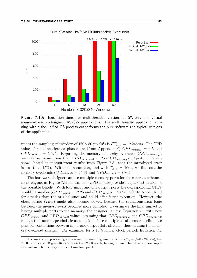
7.3. MULTITHREADING CASE STUDY 83
0
200
400
600
800
1000
1 5 10 25 50
ms
Number of 320x240 Windows
Pure SW and HW/SW Multithreaded Execution
1543ms 3075ms1036msPure SW
Typical HW/SWVirtual HW/SW
Figure 7.10: Execution times for multithreaded versions of SW-only and virtualmemory-based codesigned HW/SW applications. The multithreaded application run-ning within the unified OS process outperforms the pure software and typical versionsof the application.
mines the sampling subwindow of 160×80 pixels1) is ETHW = 12.245ms. The CPDvalues for the accelerator phases are (from Appendix E) CPDvirtual1 = 4.5 andCPDvirtual2 = 5.625. Regarding the memory hierarchy overhead (CPDvmemory),we take an assumption that CPDvmemory1 = 2 · CPDvmemory2 (Equation 5.9 canshow—based on measurement results from Figure 7.8—that the introduced erroris less than 15%). With this assumtion, and with THW = 10ns, we find out thememory overheads CPDvirtual1 = 15.61 and CPDvirtual2 = 7.805.
The hardware designer can use multiple memory ports for the contrast enhance-ment engine, as Figure 7.11 shows. The CPD metric provides a quick estimation ofthe possible benefit. With four input and one output ports the corresponding CPDswould be smaller (CPDvirtual1 = 2.25 and CPDvirtual2 = 2.625, refer to Appendix Efor details) than the original ones and could offer faster execution. However, theclock period (THW ) might also become slower, because the synchronisation logicbetween the memory ports becomes more complex. To estimate the final impact ofhaving multiple ports to the memory, the designer can use Equation 7.1 with newCPDvirtual1 and CPDvirtual2 values, assuming that CPDvmemory1 and CPDvmemory2
remain the same (a pessimistic assumption, since multiple local memories eliminatepossible contentions between input and output data streams, thus, making the mem-ory overhead smaller). For example, for a 10% longer clock period, Equation 7.1
1The sizes of the processing window and the sampling window define DC1 = (320×240×4)/4 =76800 words and DC2 = (160× 80× 4)/4 = 12800 words, having in mind that there are four inputstreams and the memory word contains four pixels.

84 7. TRANSPARENT SOFTWARE AND HARDWARE MULTITHREADING
WMU
Local Memory
WMU
Local Memory
WMU
Local Memory
WMU
Local Memory
WMU
Local Memory
Contrast Enhancement Engine
System Bus
input port input port input port input port output port
Figure 7.11: Contrast enhancement engine with multiple memory ports. The accelera-tor uses four WMU interfaces for its input ports and one WMU interface for the outputport. The VMW manager handles them as if they were ports of multithreaded hardwareaccelerators.
gives the estimation for the execution time of the contrast engine (with four inputand one output ports) ETHW = 10.697ms. The designer can use the estimation(the execution time improvement from 12.245ms to 10.697ms) for deciding whetheror not it justifies undertaking more complex design efforts.
For the purpose of another comparison, the designer may use the CPD metricfor estimating how much a faster WMU translation could improve the performance.Assuming one cycle per accelerator access through the improved WMU, the CPDswould be CPDvirtual1 = 2 and CPDvirtual2 = 2.375. Preserving the original memoryhierarchy (with only one memory port) but having the faster translation wouldresult in the overall execution time ETHW = 9.51ms. The CPD metric can be aconvenient way for the hardware designer to estimate performance before takingdesign decisions.

Chapter 8Conclusions
A Elbereth Gilthoniel,Silivren penna mırielO menel aglar elenath!Na-chaered palan-dırielO galadhremmin ennorath,Fanuilos, le linnathonNef aear, sı nef aearon!
O! Elbereth who lit the starsFrom glittering crystal slanting falls with light like jewelsFrom heaven on high the glory of the starry host.To lands remote I have looked afar,And now to thee, Fanuilos, bright spirit clothed in ever-white,I here will sing Beyond the Sea, beyond the wide and sundering Sea.
—Tolkien, The Hymn to Elbereth
THE message of this thesis regarding application-specific hardware accelerators(i.e., user hardware, semantically belonging to a particular user application)
and their integration within codesigned applications is: To simplify the interfacingbetween software and hardware and to make any programming paradigm feasible,one shall provide user hardware with system-level abstractions (e.g., virtual memory,system calls) and execution support (e.g., memory-hierarchy management, executiontransfers) already available to user software; in comparison to existing approaches,our solution is a general one—there is no limitation on the memory access patternsof hardware accelerators.
Delegating the execution steering of hardware accelerators to the system levelexposes to the user level only their pure functionality. The separation of user-level from system-level tasks fosters system-level runtime optimisations performedtransparently to the end users. It also eases software-to-hardware migrations andenables unrestricted automated hardware synthesis from high-level programminglanguages. In addition, codesigned applications become portable across differentplatforms.
Approaching to the principal concepts of general-purpose computing may seemto be compromising the performance and efficiency potential of spatial computa-tion. Notwithstanding such expectations, most of the concepts—when applied to
85

86 8. CONCLUSIONS
application-specific hardware—rather become simpler and less costly than in thegeneral-purpose case. For example, having a virtual memory hierarchy per accel-erator avoids unwanted effects of cache pollution and frequent context-switches.Furthermore, memory access patterns of hardware accelerators are less general andmore predictable in comparison to the general-purpose case: the size and the man-agement policy of the memory hierarchy can be adapted to a particular applicationfor lower cost and better performance.
What follows in this passage is a recommendation for future architects and de-signers of codesigned applications. When combining two different models of com-putation (such as temporal computation of a CPU and spatial computation of anapplication-specific hardware accelerator, both being addressed in this thesis), oneshould find a common background for the two different worlds: we have chosen thevirtual memory abstraction and the execution context of an OS process for this pur-pose. The next step would be to implement the appropriate support for the commonabstraction in the system software and system hardware—not directly visible to theapplication programmer. In our case, we have shown an implementation (especiallyapplicable to reconfigurable SoCs) of the system software and system hardware thatprovides the unified process context for codesigned applications. When designinghardware accelerators or when automating this task (by developing a synthesiser),one should apply existing (or establish, if nonexistent) conventions regarding thechosen programming paradigm. In such a way, as presented in this thesis, we followthe API and ABI rules of the host OS and the host CPU to have host-compliant hard-ware accelerators. Finally, following these guidelines (as the thesis demonstrates)gets software programmers and hardware designers to the seamless interfacing ofsoftware and hardware components of codesigned applications.
8.1 Obtained Results
For a chosen, process-based, multithreading computation model, we have proposedextensions to system software and system hardware to support unified OS processesfor heterogeneous-code applications. In experiments performed on two different re-configurable SoCs running GNU/Linux, we have demonstrated the viability of ourapproach. Our architecture (1) provides a straightforward programming paradigm—programmers are completely screened from interfacing-related memory transfers, (2)makes codesigned applications completely portable—recompiling and resynthesis-ing is sufficient, and (3) enables advanced and yet simple runtime optimisations—without any change in either application software or coprocessor hardware—andunrestricted automated synthesis.
To quantify the overhead incurred by the system-level support for unified mem-ory abstraction, we have introduced a metric for application-specific hardware accel-erators and applied it to our particular implementation. To measure overall benefitsand check the overhead, we have tested the approach by porting and running sev-eral applications with application-specific coprocessors of different complexity. Theresults show the overhead for unified memory abstraction is generally limited. Thehardware accelerators achieve significant speedups compared to software-only ex-
8.2. IMPLICATIONS 87
ecution. While our approach provides simpler interfacing, software programming,and hardware design, compared to typical existing solutions, the speedups achievedby the two approaches remain comparable.
System-level runtime optimisations can improve performance transparently tothe end user. To demonstrate a possible runtime optimisation, we have imple-mented a stream-based memory prefetch technique within the VMW manager (witha simple hardware support in the WMU). A significant execution time improvementis demonstrated, without any change in either application software or coprocessorhardware.
We have also shown a basic implementation of an unrestricted synthesis flow. Al-though at an early stage and without typical optimisation passes, our flow producesaccelerators that can speedup high-level language code without any restrictions onthe language constructions.
8.2 Implications
Designing the execution support and memory hierarchy for standard CPUs is acomplex task—the challenge is to achieve performance and cost goals for all appli-cations. On the contrary, designing the execution support and memory hierarchyfor application-specific hardware accelerators (especially having the reconfigurablehardware available) is simpler—to support the unified OS process, we keep the highabstractions from general-purpose computing but simplify the system hardware andsystem software. For example, opening more memory ports with smaller local mem-ories can be more performance-efficient than investing in a single and large localmemory with complex management policies.
Having virtual-memory-enabled hardware accelerators and the execution trans-fers supported by the system, we can imagine hardware-centric applications (i.e.,applications with its main execution thread in user hardware going back to softwarejust for the system and library calls). In such a scenario, the CPU becomes respon-sible for execution support and memory hierarchy management, running mostly onbehalf of the user hardware (e.g., executing the VMW manager actions and systemor library calls invoked by the accelerator).
Within a unified OS process, user hardware gains the access to static and dy-namic data (residing either on the stack or on the heap) of its software counterpart.The unified memory simplifies preserving constructions of high-level programminglanguages when mapping the application code from software to hardware. Anyscope policy (e.g., either static or dynamic scope) can be implemented through theshared stack, any memory-allocation policy can be implemented through the sharedheap. Supporting the code mobility and enabling unrestricted software-to-hardwaremigration opens the way toward future dynamic adaptive systems, capable of im-plementing runtime (Just-in-Time) synthesis and reconfiguration.

88 8. CONCLUSIONS
8.3 Future Research Directions
The thesis opens new research directions (1) in configurable memory hierarchies forapplication-specific hardware accelerators and (2) in automatic high-level synthesisfrom high-level programming languages.
Here we mention the differences between application-specific and general-purposevirtual memory systems that future research may exploit. In the software-only case,system architects design MMUs and memory hierarchies for the most general appli-cation mix—multiple and diverse software tasks share the MMU and the memoryhierarchy in the time-multiplexed manner. In the case of virtual-memory-enabledhardware accelerators, one can assume that a hardware accelerator owns the WMUand the memory hierarchy during the application lifetime—considerably longer pe-riod than between two context switches on a standard CPU. This fact allows (1)designing the WMU which is less-costly than standard MMUs, and (2) employingthe WMU reconfigurability to tailor the translation and the memory hierarchy closerto the application needs. The second point is especially challenging and implies theappropriate support from novel OS features to adapt the WMU and memory hierar-chy dynamically, at runtime. For example, in our experiments, we support differentsizes of the local memories accessed by hardware accelerators; also, the WMUssupport different sizes of virtual memory pages; however, for the moment, our OSextension does not adapt the memory automatically; it is a subject of future work.
Having a configurable memory hierarchy supported by the OS not only allowsruntime customisation of the virtual memory for hardware accelerators, but alsosupports OS-conducted tailoring of the application-specific coherence hardware. Thechallenge of sharing efficiently the unified memory by multiple hardware threadsoffers another research possibility toward application-specific coherence protocolsfor codesigned reconfigurable applications.
Regarding the high-level synthesis (i.e., mapping to hardware from programswritten in common high-level programming languages), unified memory abstractionfor software and hardware significantly simplifies the automatic synthesis of high-level programming languages to hardware. Mapping to hardware constructs suchas memory allocation, object creation, pointer-based accesses, and function calls,is rather difficult (or sometimes impossible) without the unified process concept.Our initial results allow the synthesis community to investigate unrestricted codemigration from software to hardware, even dynamically at runtime (which is thebiggest future challenge).
Apart from showing the viability of the unified process concept, the researchwork presented in this thesis calls forth immediate extensions and improvements.The analyses (qualitative and quantitative) presented in the thesis have shown theoverheads of the applied scheme. One of the first tasks of future efforts shall be totackle the overheads and try minimising their effects.
Although we do not address management of reconfigurable hardware and its re-configuration in this thesis, we recommend the integration of the presented interfacemanagement with the resource management (addressed in the related work) to builda full-fledged OS extensions for codesigned reconfigurable applications. With appro-priate extensions in binary file formats (such as Executable and Linkable Format—
8.3. FUTURE RESEARCH DIRECTIONS 89
ELF) and the OS support, an application loader could automatically reconfigure anFPGA resource preparing the user hardware at the application start-time. Furtheron, an FPGA-aware dynamic linker could reconfigure, if needed, the FPGA fabricat runtime. The challenge is to find efficient solutions for task partitioning andconfiguration scheduling, and to hide performance drawbacks incurred by FPGAconfiguration times.
The dynamic prefetching in the system layer responsible for the unified memoryabstraction between user software and user hardware has demonstrated significantperformance improvements. As the currently employed technique handles stream-based memory accesses, future runtime optimisations may address other memoryaccess patterns (e.g., pointer chasing) with appropriate extensions in the systemsoftware (the VMW manager) and system hardware (the WMU). The dynamicnature of these techniques may allow the VMW manager to follow the performanceand select at runtime the best prefetching policy for a given hardware accelerator.Dynamic optimisation techniques are not limited to prefetching: other techniquesmay include adapting the memory hierarchy for a particular application, in-advancehardware reconfiguration, and optimising the execution transfers from software tohardware and vice versa.
To enable and foster the widespread presence and use of reconfigurable comput-ing, future work shall address integrating compilers and synthesisers into a singlecompilation tool. Starting from a program written in a high-level programminglanguage, the tool shall try to exploit the available parallelism and generate HDLdescriptions of hardware accelerators complying to the host processor ABIs. Withthe unified OS process supporting stack frames and calling sequences, treating anyhigh-level language and generating its runtime support code (in both software andhardware) shall be feasible. Finally, having widely-accepted programming languagescompiled by tools with no synthesis and partitioning restrictions would offer ben-efits of spatial computation in application-specific hardware to a large number ofgeneral-purpose computer users.

90 8. CONCLUSIONS

Appendix AWMU Interface
THE WMU defines the hardware interface of virtual-memory-enabled hardwareaccelerators. It decouples the accelerator design from the host platform. The
WMU is a platform-specific element ported once per reconfigurable SoC; differentapplications on the same platform reuse the same WMU. In this appendix, weexplain the WMU interface toward hardware accelerators.
A.1 Hardware Interface
The WMU provides hardware support for translation of the virtual addresses gener-ated by the accelerator. If possible, the WMU translates virtual addresses demandedby the coprocessor (similarly as the MMU does for the user application running onthe main processor) to real addresses of the local memory region. Otherwise, theWMU generates an interrupt to request the OS handling, while the hardware accel-erator is stalled.
To foster the accelerator reuse and portability across different platforms, we ac-cept a common interface between the WMU and the accelerator. We standardisethe interface for both platforms that we use. Should we use another platform in thefuture, the basic WMU interface would not change. Figure A.1 shows how a virtual-memory-enabled hardware accelerator is interconnected to the WMU. The standardinterface consists of virtual address lines (hwacc_vaddr), data lines (hwacc_din andhwacc_dout), byte enable lines (hwacc_be) and control lines. The control signalsbetween the accelerator and the WMU are the following: (1) hwacc_start, theaccelerator start signal, issued by the WMU once a user initiates the executiontransfer; (2) hwacc_access, the accelerator access signal, indicates that there isan access currently performed by the accelerator; (3) hwacc_wr, the acceleratorwrite signal, indicates that the access is a write; (4) hwacc_tlbhit, the translationhit signal, indicates that an address translation is successful—in order to proceedwith a memory access, the accelerator should first wait for this signal to appear;(5) hwacc_fin, the accelerator completion signal, indicates to the WMU that theaccelerator has finished its operation. The WMU is connected to the host plat-form through platform-specific signals (e.g., the physical address lines of the localmemory).
91

92 A. WMU INTERFACE
--
-- hardware accelerator ports complying to the WMU interface
--
entity hwacc edge is
generic (
HWACC DATA WIDTH : positive := 64;
HWACC ADDR WIDTH : positive := 32
);
port(
hwacc din : in std logic vector (HWACC DATA WIDTH-1 downto 0);
hwacc dout : out std logic vector (HWACC DATA WIDTH-1 downto 0);
hwacc addr : out std logic vector (HWACC ADDR WIDTH-1 downto 0);
hwacc be : out std logic vector (HWACC DATA WIDTH/8-1 downto 0);
hwacc access : out std logic;
hwacc xchange : out std logic;
hwacc wr : out std logic;
hwacc inv : out std logic;
hwacc fin : out std logic;
hwacc start : in std logic;
hwacc tlbhit : in std logic;
hwacc clk : in std logic;
hwacc reset : in std logic
);
end entity hwacc edge;
Figure A.1: The VHDL code of the WMU interface for hardware accelerators. Con-necting a virtual-memory-enabled hardware accelerator to the WMU interface requiresusing the ports shown in the figure.
A.2 Parameter Exchange
The WMU contains a register file that the VMW manager uses for parameter ex-change between user software and user hardware. The register file is of the limitedsize (current WMU implementations have eight 32-bit registers used for this pur-pose); if invoking the hardware accelerator needs more parameters, either the userstack or any other region in the main memory can be used for this purpose—thisposes no problem since the hardware accelerator is capable of accessing the virtualmemory address space. Having the register file in the WMU makes the parameterexchange faster—in most cases there is no need to access the memory.
Figure A.2 shows the timing diagram for the parameter exchange. When theuser program launches the sys_hwacc system call, the VMW writes a start bit inthe WMU control register, which, in turn, starts the execution of the acceleratorby asserting the hwacc_start signal. This indicates that the accelerator shall startreading the input parameters by generating the exchange register file addresses.During this phase, the accelerator asserts the hwacc_xchange signal, meaning thatthe addresses on the address lines are intended for the register file. The usageof the registers is the following: (1) the register at the address 0x0000 holds thenumber of accelerator parameters (nparam); (2) the register at the address 0x0001
contains control flags (flags) which are optional; (3) the rest of the registers (theaddresses from 0x0002 to 0x0007) store the parameters used to invoke the acceler-ator (param[0-2] in this particular case). In the case of more than six parameters,the register at the address 0x0007 is a pointer to the memory region (or the stack)where the accelerator can find the remaining parameters. Appendix B shows theusage of the parameter exchange structure in software.

A.2. PARAMETER EXCHANGE 93
clk
hwacc_xchange
hwacc_din
hwacc_start
hwacc_vaddr0x0000 0x0001 0x0002 0x0003 0x0004
nparam flags param[0] param[1] param[2]
hwacc_access
0x0004
Figure A.2: Timing diagram showing the accelerator start up. The WMU sets thehwacc start signal which starts the accelerator. The accelerator generates accessesin the exchange mode (the hwacc xchange is asserted), reading parameters from theexchange register file. Afterward, the accelerator starts normal operation, accessing thevirtual memory (the hwacc access signal is one).
Once the initialisation is over, the accelerator starts normal operation and ac-cesses the virtual memory. During the memory accesses, the accelerator sets thehwacc_access signal to one, puts the valid address, and waits for the reception ofthe hwacc_tlbhit signal. Receiving the signal means that the translations is overand the requested data is available at the data input lines. Figure C.3 shows anexample of such access.
Figure A.3 shows the timing diagram for the accelerator completion. After fin-ishing the computation, the accelerator returns back to software. If the acceleratorproduced a return value (we use the C language semantics), it returns it back tosoftware through the exchange register file of the WMU. Before signalising the com-pletion (by asserting the signals hwacc_fin and hwacc_access), the acceleratorwrites the return value and the return code to the WMU. The return code is nec-essary for the VMW manager to distinguish the situation when a normal returnsappears from the hardware callback to software. If the value stored by the accelera-tor at the address 0x0001 of the register file differs from the return code, the VMWmanager uses it for invoking the appropriate software function. The rest of theregisters (from address 0x0002 to address 0x0007) are at the accelerator disposalfor passing parameters to software.
The completion of the accelerator operation raises an interrupt handled by theVMW manager. Acknowledging the interrupt resets the interrupt bit of the WMUstatus registers. Then, the VMW manager clears the start bit in the WMU controlregister, which, in turn, puts the hwacc_start signal to zero. The accelerator usesthe change of this signal (if there is no callback to software pending) to go to itsinitial state. In this way, it is ready for future invocations.
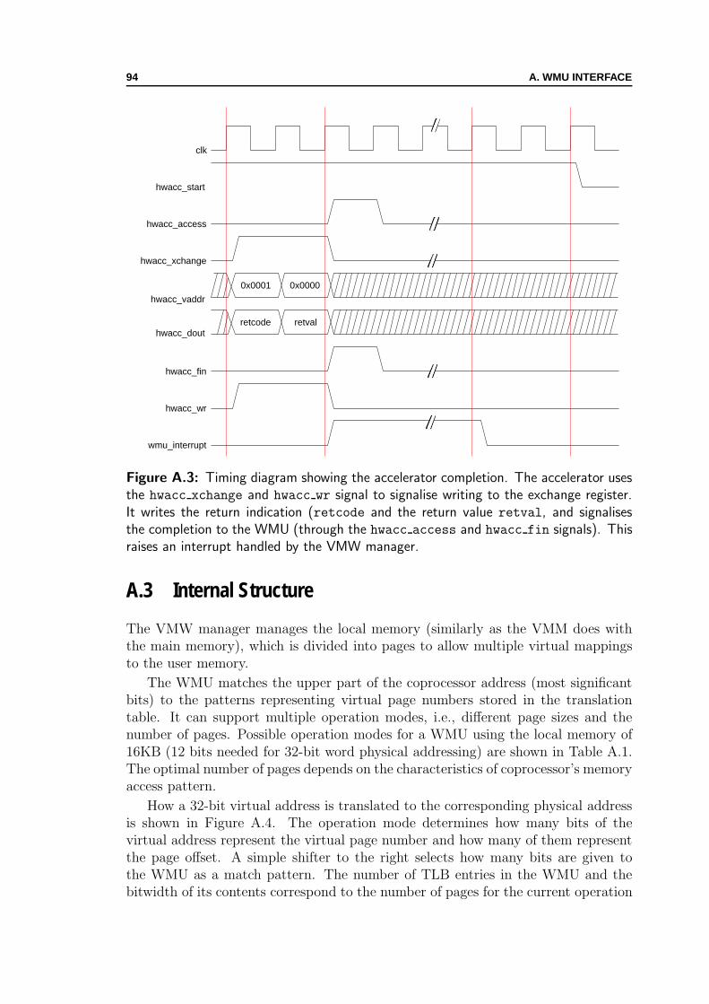
94 A. WMU INTERFACE
clk
hwacc_xchange
hwacc_dout
hwacc_start
hwacc_vaddr
retcode retval
hwacc_access
0x0001 0x0000
hwacc_fin
hwacc_wr
wmu_interrupt
Figure A.3: Timing diagram showing the accelerator completion. The accelerator usesthe hwacc xchange and hwacc wr signal to signalise writing to the exchange register.It writes the return indication (retcode and the return value retval, and signalisesthe completion to the WMU (through the hwacc access and hwacc fin signals). Thisraises an interrupt handled by the VMW manager.
A.3 Internal Structure
The VMW manager manages the local memory (similarly as the VMM does withthe main memory), which is divided into pages to allow multiple virtual mappingsto the user memory.
The WMU matches the upper part of the coprocessor address (most significantbits) to the patterns representing virtual page numbers stored in the translationtable. It can support multiple operation modes, i.e., different page sizes and thenumber of pages. Possible operation modes for a WMU using the local memory of16KB (12 bits needed for 32-bit word physical addressing) are shown in Table A.1.The optimal number of pages depends on the characteristics of coprocessor’s memoryaccess pattern.
How a 32-bit virtual address is translated to the corresponding physical addressis shown in Figure A.4. The operation mode determines how many bits of thevirtual address represent the virtual page number and how many of them representthe page offset. A simple shifter to the right selects how many bits are given tothe WMU as a match pattern. The number of TLB entries in the WMU and thebitwidth of its contents correspond to the number of pages for the current operation

A.3. INTERNAL STRUCTURE 95
Number of pages Page size VirtPage bits PhyPage bits Offset bits
2 8KB 21 1 114 4KB 22 2 108 2KB 23 3 916 1KB 24 4 832 0.5KB 25 5 7
Table A.1: WMU operation modes. Different number of local memory pages aresupported by the WMU.
TLB
MatchPattern
MatchTranslation
VirtPage No Offset
Shift Right
Concat
OpMode
Physical Address
Virtual Address
PhyPage No Offset
Figure A.4: WMU address translation and multiple operation modes. The WMU formsthe appropriate physical address depending on the current operation mode.
mode. At the WMU exit, a concatenator forms the correct physical address. Thecurrent operation mode determines how many of the match translation and offsetbits are needed to form an address for the 4K words local memory. The OS controlsthe WMU and could adapt its operation mode to application requirements, evenduring application runtime.

96 A. WMU INTERFACE
Appendix BVMW System Call
THE VMW manager is responsible for the translation process and memorytransfers. Besides, it also defines the programming interface for using virtual-
memory-enabled hardware accelerators. The interface consists of a system call thatperforms the execution transfer from user software to user hardware and passes thenecessary parameters. It also provides some auxiliary functions that we use for themeasurement and control purposes. In this appendix, we show the programminginterface and give the details of its use, and we explain the invocation of hardwareaccelerators from software.
B.1 VMW Programming
We extend the host OS with a system call sys_hwacc that is responsible for theinterface between use software and user hardware. In our particular implementation,the VMW manager is an OS module loadable at runtime. Once the it is loaded andlinked to the kernel, the module hooks the sys_hwacc call into the dispatch tablefor system services. Further on, the programmer can use it for configuring andaccessing hardware accelerators.
Before invoking a hardware accelerator, the programmer has to make sure thatthe FPGA contains the accelerator. In our work we do not address possibilities ofdynamic reconfiguration. We just provide means for configuring the FPGA beforethe particular codesigned application is run. In the case of the Altera device (dis-cussed in Appendix C), we create a special device with the appropriate support inthe OS. Copying a bitstream file (the file containing the configuration bits for theprogrammable logic—it is the outcome of the Altera design tools) to the special de-vice reconfigures the chip and puts the required hardware accelerator in place. Thisenabled further references to the accelerator through the sys_hwacc call. Althoughthe Xilinx device (also explained in Appendix C) should support partial runtimereconfiguration, the design flow could not produce designs for reconfiguration (thisflaw in the design tools has been corrected in the latest version of the tools). Thus,in the Xilinx case, we had to configure the system (with all required hardware accel-erators, WMUs, and local memories) statically, at start up time, before launchingthe operating system.
97
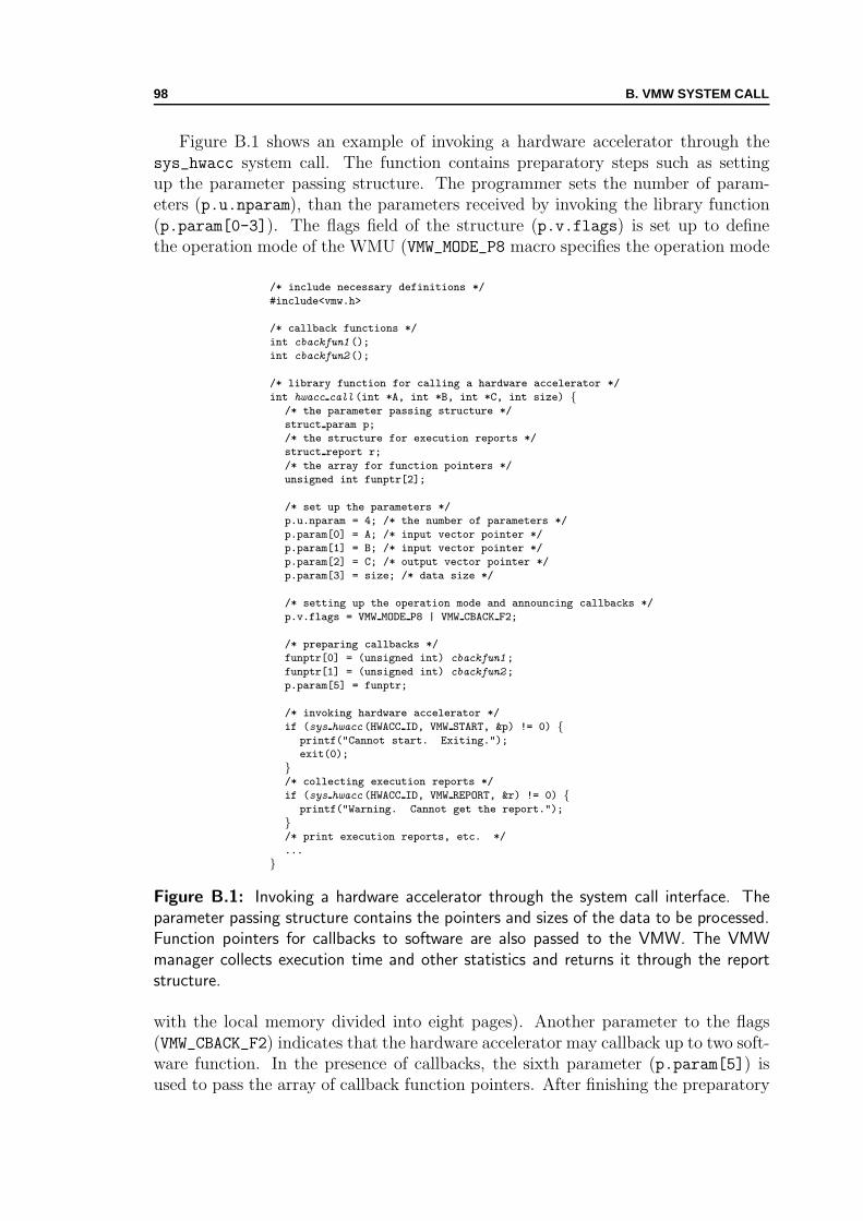
98 B. VMW SYSTEM CALL
Figure B.1 shows an example of invoking a hardware accelerator through thesys_hwacc system call. The function contains preparatory steps such as settingup the parameter passing structure. The programmer sets the number of param-eters (p.u.nparam), than the parameters received by invoking the library function(p.param[0-3]). The flags field of the structure (p.v.flags) is set up to definethe operation mode of the WMU (VMW_MODE_P8 macro specifies the operation mode
/* include necessary definitions */
#include<vmw.h>
/* callback functions */
int cbackfun1 ();
int cbackfun2 ();
/* library function for calling a hardware accelerator */
int hwacc call (int *A, int *B, int *C, int size) {/* the parameter passing structure */
struct param p;
/* the structure for execution reports */
struct report r;
/* the array for function pointers */
unsigned int funptr[2];
/* set up the parameters */
p.u.nparam = 4; /* the number of parameters */
p.param[0] = A; /* input vector pointer */
p.param[1] = B; /* input vector pointer */
p.param[2] = C; /* output vector pointer */
p.param[3] = size; /* data size */
/* setting up the operation mode and announcing callbacks */
p.v.flags = VMW MODE P8 | VMW CBACK F2;
/* preparing callbacks */
funptr[0] = (unsigned int) cbackfun1;
funptr[1] = (unsigned int) cbackfun2;
p.param[5] = funptr;
/* invoking hardware accelerator */
if (sys hwacc (HWACC ID, VMW START, &p) != 0) {printf("Cannot start. Exiting.");
exit(0);
}/* collecting execution reports */
if (sys hwacc (HWACC ID, VMW REPORT, &r) != 0) {printf("Warning. Cannot get the report.");
}/* print execution reports, etc. */
...
}
Figure B.1: Invoking a hardware accelerator through the system call interface. Theparameter passing structure contains the pointers and sizes of the data to be processed.Function pointers for callbacks to software are also passed to the VMW. The VMWmanager collects execution time and other statistics and returns it through the reportstructure.
with the local memory divided into eight pages). Another parameter to the flags(VMW_CBACK_F2) indicates that the hardware accelerator may callback up to two soft-ware function. In the presence of callbacks, the sixth parameter (p.param[5]) isused to pass the array of callback function pointers. After finishing the preparatory
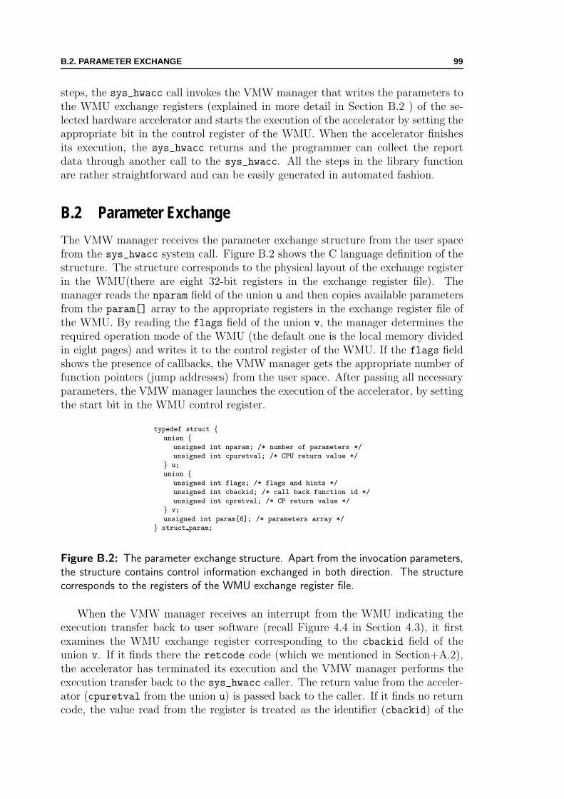
B.2. PARAMETER EXCHANGE 99
steps, the sys_hwacc call invokes the VMW manager that writes the parameters tothe WMU exchange registers (explained in more detail in Section B.2 ) of the se-lected hardware accelerator and starts the execution of the accelerator by setting theappropriate bit in the control register of the WMU. When the accelerator finishesits execution, the sys_hwacc returns and the programmer can collect the reportdata through another call to the sys_hwacc. All the steps in the library functionare rather straightforward and can be easily generated in automated fashion.
B.2 Parameter Exchange
The VMW manager receives the parameter exchange structure from the user spacefrom the sys_hwacc system call. Figure B.2 shows the C language definition of thestructure. The structure corresponds to the physical layout of the exchange registerin the WMU(there are eight 32-bit registers in the exchange register file). Themanager reads the nparam field of the union u and then copies available parametersfrom the param[] array to the appropriate registers in the exchange register file ofthe WMU. By reading the flags field of the union v, the manager determines therequired operation mode of the WMU (the default one is the local memory dividedin eight pages) and writes it to the control register of the WMU. If the flags fieldshows the presence of callbacks, the VMW manager gets the appropriate number offunction pointers (jump addresses) from the user space. After passing all necessaryparameters, the VMW manager launches the execution of the accelerator, by settingthe start bit in the WMU control register.
typedef struct {union {
unsigned int nparam; /* number of parameters */
unsigned int cpuretval; /* CPU return value */
} u;
union {unsigned int flags; /* flags and hints */
unsigned int cbackid; /* call back function id */
unsigned int cpretval; /* CP return value */
} v;
unsigned int param[6]; /* parameters array */
} struct param;
Figure B.2: The parameter exchange structure. Apart from the invocation parameters,the structure contains control information exchanged in both direction. The structurecorresponds to the registers of the WMU exchange register file.
When the VMW manager receives an interrupt from the WMU indicating theexecution transfer back to user software (recall Figure 4.4 in Section 4.3), it firstexamines the WMU exchange register corresponding to the cbackid field of theunion v. If it finds there the retcode code (which we mentioned in Section+A.2),the accelerator has terminated its execution and the VMW manager performs theexecution transfer back to the sys_hwacc caller. The return value from the acceler-ator (cpuretval from the union u) is passed back to the caller. If it finds no returncode, the value read from the register is treated as the identifier (cbackid) of the

100 B. VMW SYSTEM CALL
callback request. The manager performs the execution transfer from user hardwareto user software (as explained in Section 6.2), and passes possible parameters forinvoking the callback software function. It determines the number of parametersby reading the WMU register corresponding to the nparam field of the u union andreads the parameters from the exchange register file (the registers correspondingto the param[] array of the exchange structure). Finally, the cbackid determineswhich function pointer the VMW manager shall use for setting up the jump addresson the user stack (recall Figure 6.3). When the callback function finishes, the tram-poline on the user stack returns back the execution to the VMW manager. Themanager copies the return value received from the callback function to the WMUexchange register file and resumes the execution of the hardware accelerator. Theaccelerator, in turn, reads the return value through the parameter exchange protocol(discussed in Appendix A) and continues the execution until another callback or thefinal completion.

Appendix CReconfigurable SoC Platforms
WE have implemented the VMW system on two different reconfigurable SoCscoming from major FPGA vendors. We use an in-house-made board (called
RokEPXA and shown in Figure C.1) based on an Altera Excalibur device [3], andthe ML310 board based on a Xilinx Virtex-II Pro device [130]. We have designed theWMU in VHDL to be synthesised onto FPGA together with a hardware accelerator.We have developed the VMW manager as a Linux kernel module and ported itto both platforms. The VMW manager can support prefetching (as explained inChapter 4). The following sections explain in more detail the two platforms.
C.1 Altera Excalibur Platform
Figure C.1 shows the RokEPXA board (designed by Gaudin [48]) that we usedfor our experiments. The main components of the board are the Altera ExcaliburEPXA1 device [3], 64MB of SDRAM memory at 266MHz, 8MB of FLASH mem-ory, Ethernet module, serial and USB ports, and various expansion and debuggingports. The development and cross compiling platform (on a standard workstation)is connected to the board over serial and network interfaces.
The Excalibur EPXA1 device we use is the smallest device in its family (e.g.,EPXA4 and EPXA10 devices from the same family offer more programmable logicand larger on-chip memories). Figure C.2 shows a simplified scheme of the inter-nal organisation of the EPXA1 device. It consists of a fixed ASIC part, calledEmbedded Processor Stripe in Altera’s terminology, and of a programmable partcalled PLD—standing for Programmable Logic Device. The stripe contains theARM922T processor with a cache and memory management unit. The processorruns at 133MHz. Other major components of the stripe are: (1) 32KB of single-port on-chip SRAM memory; (2) 16KB of dual-port on-chip SRAM memory alsoaccessible by the programmable logic; (3) SDRAM controller; (4) JTAG interfacefor debugging. Internal on-chip peripherals are connected with the CPU over twoAMBA buses for high-speed peripherals (AHB1 and AHB2 [8]). The main CPUcan configure the PLD at runtime through a PLD configuration controller. In con-trast to Xilinx Virtex-II Pro devices, partial configuration of the PLD device isnot possible—the whole device has to be configured at once. However, most of the
101

102 C. RECONFIGURABLE SOC PLATFORMS
Figure C.1: RokEPXA board. The board is based on Excalibur reconfigurable SoCcontaining ARM processor and reconfigurable logic.
peripherals necessary for the normal system functioning are already present in theembedded processor stripe (which is not the case in Xilinx devices), thus, albeit thelimitation, the reconfiguration process is made simpler.
We have designed and synthesised the WMU within the PLD device of theEPXA1 chip. Figure C.2 shows the WMU integration within the EPXA1. Sincethe dual-port on-chip SRAM is accessible by both the stripe and the PLD, we havechosen it for the local memory of the virtual-memory-enabled hardware accelerator.The VMW manager running on the ARM processor transfers the pages between themain memory and the dual-port memory using the AMBA bus. Hardware accel-erators access the dual-port memory through the WMU using the WMU-interfaceprotocol (shown in Appendix A). Depending on the WMU operation mode, thememory is logically organised in 2–32 pages with respective page sizes 8–0.5KB (thetotal size is therefore 16KB). The WMU part of the PLD design is fixed, designing anew hardware accelerators assumes just changing the HW ACC block in the design.The WMU is connected to the rest of the platform over the slave AMBA interface.Through this interface the VMW manager accesses the WMU and manages thetranslation.
Because of the limitations of the FPGA technology, the translation is performedin multiple cycles: if we assume no translation faults, four cycles are needed from themoment when the accelerator generates an access to the moment when the data isread or written (Figure C.3). The performance drop caused by multiple translationcycles can be overcome by pipelining. Although we had to implement the WMU inFPGA for these experiments, WMUs should, in principle, be implemented as ASICcores, in the same way as MMUs are.

C.1. ALTERA EXCALIBUR PLATFORM 103
AHB1
ARM922T+ Cache+ MMU
SDRAMController
AHB1-2Bridge
AHB2
UART
SDRAM
EBI
Flash, ROM, SRAM
RS232
Single-PortSRAM
Dual-PortSRAM
WMU
Timer
Stripe-to-PLDBridge
AHB Master Port
AHB Slave Port
HW ACC(User Logic)
PLD
Stripe
Altera Excalibur EPXA1
VMW SW Interface
VMW HW Interface
Figure C.2: WMU integration within Altera Excalibur EPXA1 device. The ASIC partof the device (Stripe) contains the ARM processor, on-chip memories, and peripherals.The reconfigurable part of the device (PLD) is used for the WMU and the application-specific hardware accelerator. A 16KB dual-port memory accessible by Stripe and PLDis used for the local memory of the accelerator.
The board is running GNU/Linux OS read from the FLASH memory at boottime. It uses the 64MB of the main memory for the working memory and the rootfile system. We originally developed the VMW manager for the Altera platform;however, it is easily portable to other platforms by adapting few configuration files.The manager is a loadable kernel module that can be added to the kernel at runtime. The Linux kernel version the VMW relies on is 2.6 [75]. For reconfiguring thePLD we use a special character device supported by the module. In this way, onecan configure the PLD by just issuing the following shell command: “cp bitstreamfile/dev/pld”. Similarly, a program can do the same by invoking the appropriate systemcalls.

104 C. RECONFIGURABLE SOC PLATFORMS
clk
CP_VADDR
CP_ACCESS
CP_TLBHIT
CP_DIN
Figure C.3: The accelerator read access. The accelerator initiates the data transferand waits for the confirmation signal. The Data is ready on the fourth rising edge ofthe clock.
C.2 Xilinx Virtex-II Pro Platform
The ML310 board [130] from Xilinx that we also used for our experiments is an ad-vanced evaluation board containing the Xilinx Virtex-II Pro device XC2VP30. Theboard is equipped with 256MB of DDR RAM, 512 MB of CompactFlash memory,four PCI expansion slots, RS232 and USB serial interfaces, two IDE connectors,JTAG debugging interface, etc. Figure C.4 shows the ML310 evaluation board.
The XC2VP30 device contains two PowerPC 405 processors surrounded byFPGA logic (30000 logic cells). Except the two CPUs, the device has no otherASIC cores, meaning that the designer has to implement system peripheral devices(e.g., DDR RAM controller, UART, interrupt controller) in FPGA. The PowerPCprocessors can run at frequencies up to 300MHz. On-chip processor buses (PLB,OPB, and OCM [59]) and DDR RAM memory can run at the frequency of 100MHz.
Figure C.5 shows the architecture used for our experiments on the ML310 Xil-inx evaluation board—in our experiments we use only one of the two PowerPCprocessors available. The CPU is connected to the Processor Local Bus (PLB). Theexternal RAM controller is also connected to the same bus. Slower peripherals,such as UART and interrupt controller, are connected to the On-chip PeripheralBus (OPB). We have connected the WMU to the same bus. The CPU controlsthe slower peripherals, such as UART, WMU and interrupt controller, through thePLB2OPB bridge. We use multiple on-chip memory blocks (BRAMs) to form thelocal memory of hardware accelerators (VMW Memory in Figure C.5). A BRAMblock is a dual-port memory of configurable size. To simplify the design, we haveoriginally connected the local memory to the OPB bus. This, however, has givenunsatisfactory performance results. Our next step was to connect the local memoryto the PLB bus, closer to the CPU and the memory. Nevertheless, this has neither

C.2. XILINX VIRTEX-II PRO PLATFORM 105
Figure C.4: ML310 board. The board is based on Virtex-II Pro reconfigurable SoCcontaining two PowerPC processors surrounded by FPGA logic.
improved performance. Unexpectedly, albeit the difference in running frequencies,the transfer times of the Altera Excalibur device were shorter than the correspond-ing Virtex-II Pro times. We have investigated the corresponding low-level kernelroutines used by the VMW manager in both cases (ARM and PowerPC implemen-tations of the Linux kernel). We found both implementations were assembler-basedand highly optimised. Only when we excluded the PowerPC from the page transferpath and employed a DMA on the local memory side (as Figure C.5 shows), we havemanaged to get satisfactory performance results (Section 5.3.5 shows difference incopy times between the Altera and the Xilinx platforms). In the system configura-tion used for the experiments, the VMW manager just initiates data transfers fromthe main memory to the VMW memory (and vice versa); then, it is on the DMAto perform the task.
There is another peculiarity regarding our WMU implementation on Xilinx Vir-tex devices. We use LookUp Tables (LUTs) configured as shift registers (as recom-mended in a Xilinx Application Note—XAPP201 [130]) to implement the ContentAddressable Memory (CAM) of the TLB. The implementation results in a CAMspending one cycle per pattern match. However, in the management phase, whena pattern is to be written in the CAM, one cycle per pattern bit is necessary. Forexample, writing a 24 bit pattern requires 24 cycles. As the management access ap-
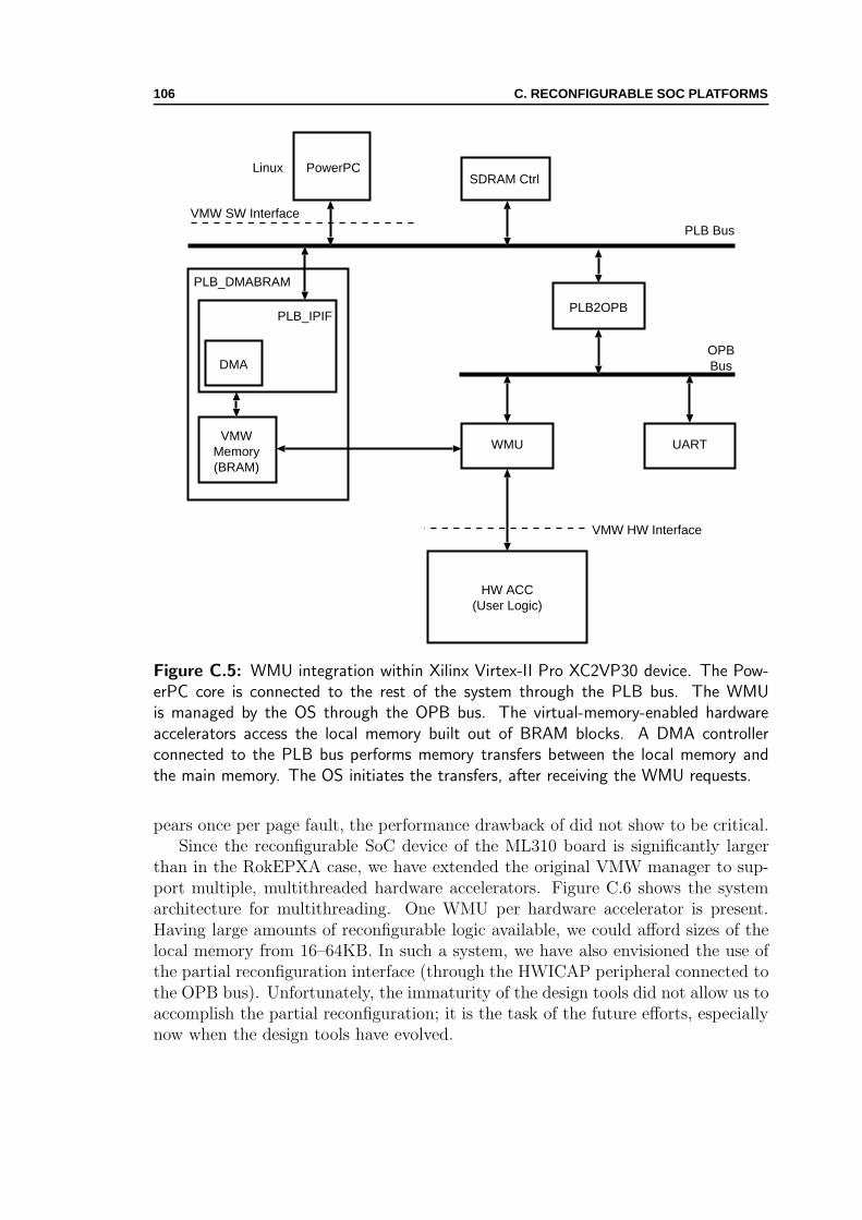
106 C. RECONFIGURABLE SOC PLATFORMS
PLB Bus
PowerPCSDRAM Ctrl
PLB2OPB
OPBBus
UARTVMW
Memory(BRAM)
HW ACC(User Logic)
DMA
PLB_IPIF
PLB_DMABRAM
WMU
Linux
VMW HW Interface
VMW SW Interface
Figure C.5: WMU integration within Xilinx Virtex-II Pro XC2VP30 device. The Pow-erPC core is connected to the rest of the system through the PLB bus. The WMUis managed by the OS through the OPB bus. The virtual-memory-enabled hardwareaccelerators access the local memory built out of BRAM blocks. A DMA controllerconnected to the PLB bus performs memory transfers between the local memory andthe main memory. The OS initiates the transfers, after receiving the WMU requests.
pears once per page fault, the performance drawback of did not show to be critical.Since the reconfigurable SoC device of the ML310 board is significantly larger
than in the RokEPXA case, we have extended the original VMW manager to sup-port multiple, multithreaded hardware accelerators. Figure C.6 shows the systemarchitecture for multithreading. One WMU per hardware accelerator is present.Having large amounts of reconfigurable logic available, we could afford sizes of thelocal memory from 16–64KB. In such a system, we have also envisioned the use ofthe partial reconfiguration interface (through the HWICAP peripheral connected tothe OPB bus). Unfortunately, the immaturity of the design tools did not allow us toaccomplish the partial reconfiguration; it is the task of the future efforts, especiallynow when the design tools have evolved.

C.2. XILINX VIRTEX-II PRO PLATFORM 107
PLB Bus
PowerPCSDRAM Ctrl
PLB2OPB
OPBBus
UARTWMU
VMWMemory(BRAM)
HW ACC(User Logic)
DMA
PLB_IPIF
HW ACC(User Logic)
...
PLB_WMU
WMU
VMWMemory(BRAM)
DMA
PLB_IPIF
PLB_WMU
MemoryCoherence
HWICAP
PartialReconfiguration
Linuxor
Standalone
...
VMW HW Interface
VMW SW Interface
Figure C.6: Xilinx Virtex-II Pro XC2VP30 platform for multithreading. Multiple WMUsconnect user hardware accelerators to the rest of the system. The user reconfigures theaccelerators through the HWICAP peripheral.

108 C. RECONFIGURABLE SOC PLATFORMS
Appendix DApplications
IN this appendix, we show design details of a couple of hardware accelerators thatwe used in our experiments. We show the design of the IDEA cryptography ac-
celerator and the design of the contrast enhancement engine for image processing.In both cases, we have taken already existing accelerators designed in synthesisableVHDL [17, 111, 124, 32]) and adapted them for our virtual memory interface. Theoriginal IDEA accelerator encrypts the data stored in local memory, while the orig-inal contrast engine directly accesses the main memory. In this way, the originalaccelerators represent two typical architectures (accessing local memory and mainmemory) described in Section 2.2. The experiments we performed with the virtual-memory-enabled accelerators have shown in practice the advantages of using ourvirtualisation layer. It simplifies the hardware interfacing and software program-ming, and allows porting applications from one platform to another without anychange in the application code.
D.1 IDEA Accelerator Design
We have used the reference IDEA code [82] design together with a previous designin synthesisable VHDL [17] as the basis for designing the virtual-memory-enabledIDEA accelerator. The IDEA algorithm consists of eight rounds of the core trans-formation followed by the output transformation. When designing the accelerator,the eight rounds can be “unrolled” a certain number of times, depending on theavailable reconfigurable logic resources. The computation of a round contains fourmultiplications, four additions, and several XOR operations. The output transfor-mation consists of two multiplications and two additions. The algorithm exhibitsparallelism exploitable by hardware implementation.
Figure D.1 shows the design blocks of the original IDEA accelerator withoutVMW (a typical accelerator accessing local memory). There are four principaldesign blocks of the accelerator. The IDEA Core and the IDEA CTRL blocksrepresent the algorithm core and its controller. The Memory CTRL and Init CTRLblocks provide actual communication to the core. IDEA Core and Memory CTRLare synchronised using the stall signal: the core is stalled until Memory CTRL isready to read/write the data.
109

110 D. APPLICATIONS
Memory CTRL
clk2
IDEA CTRL
clk1
startstall
paramsCout
rd_req wr_req
IDEA Core
clk1Cin
stall
X
Y
Local Memory µProc
Memory and µProc Interface
InitCTRL
clk2
fin
Figure D.1: Typical IDEA accelerator accessing local memory. The accelerator isinterfaced directly to local memory. It generates physical memory addresses to accessthe data.
The IDEA core implements the eight computation rounds of the algorithm andthe output transformation. The core performs the computation rounds iteratively—the rounds are not “unrolled” because of the limited FPGA space (we have originallytargeted the Altera EPXA1 device, which is rather small in terms of available logiccells). The original pipeline depth of the IDEA round implementation [17] is fivestages. The output transformation has only one stage. To obtain a smaller design,we have changed the available design of the IDEA core [121]. The multipliers andadders in the IDEA round pipeline are used in a time-multiplexed manner to lowertheir number (two multipliers and two adders).
Memory CTRL
clk2
IDEA CTRL
clk1
startstall
params
init_ctrl
Cout
rd_req wr_req
IDEA Core
clk1Cin
stall
X
Y
WMU Interface
Local Memory µProc
Memory and µProc Interface
InitCTRL
clk2
fin
init
hwacc_access
hwacc_wr
hwacc_addrhwacc_tlbhit
hwacc_{fin,xchng}hwacc_starthwacc_din
hwacc_doutWMU
Figure D.2: Virtual-memory-enabled IDEA accelerator. The accelerator is interfacedthrough a standardised WMU interface and generates no physical addresses.

D.2. CONTRAST ENGINE DESIGN 111
Figure D.2 shows the virtual-memory-enabled version of the IDEA accelerator.It consists of the same four design blocks as in the typical accelerator case, butwith the memory access unit and the initialisation unit changed to comply with theWMU interface. One can notice that the IDEA-specific blocks are unmodified and,although slightly different, both Memory CTRL and Init CTRL must be present inone form or another—the main difference is that they now generate virtual addressesand not the physical addresses of the local memory. To avoid performance penaltiesbecause of the relatively complex core design compared to the interface components,the core blocks belong to a different clock domain (clk1’s period is an integralfraction of clk2’s). Synchronisation is again achieved using the stall signal (thecore blocks until the memory request is fulfilled; afterward, it can continue theexecution).
Once the WMU starts the accelerator with hwacc_START, Init CTRL takes con-trol. It reads initialisation parameters through the WMU and passes them to theIDEA CTRL block (params). After passing all parameters, it gives the interface ac-cess to the memory controller (the init signal that controls the multiplexers allowsMemory CTRL access to the WMU interface) and starts IDEA CTRL (start).IDEA CTRL controls the computation of IDEA Core and generates memory re-quests to Memory CTRL (rd_req, wr_req). Memory CTRL in its turn stalls(stall) the core unless it is ready to respond to the requests. For each request,it generates the appropriate WMU interface signals (hwacc_access, hwacc_wr,hwacc_vaddr, hwacc_dout), waits for the hit acknowledgment arriving from theTLB. (hwacc_tlbhit), and eventually reads the input data lines (hwacc_din).When the computation is finished, IDEA CTRL passes the control back to INITCTRL (fin), which informs the WMU about the successful completion, writes thereturn code and return value (recall Appendix A) to the exchange register file, andfinishes the accelerator computation (hwacc_fin).
After synthesis for the Altera Excalibur device and the Xilinx Virtex-II Pro de-vice, the complex IDEA accelerator core runs on lower frequency (6MHz—Altera,25MHz—Xilinx) than the WMU and the IDEA memory subsystem (24MHz—Altera,100MHz—Xilinx). For improving the processing throughput, the core of the IDEAaccelerator is pipelined. However, due to the limited FPGA resources of the EPXA1device, only three 64-bit blocks can be encrypted at a time. With larger FPGAs(such as EPXA10 from Altera or XC2VP30 from Xilinx) additional parallelism couldbe exploited. Nevertheless, we decide to use the single IDEA accelerator design thatcan fit both target device.
D.2 Contrast Engine Design
Starting from image-processing engines (developed by Stechele et al. [111, 124, 32])that access the system main memory, we have built virtual-memory-enabled accel-erators for the contrast enhancement and edge detection applications. The mainintention of the original designers was to build a reconfigurable system for driverassistance applications. In this context, the system uses different hardware accel-erators for processing camera-captured frames in different driving conditions [111].
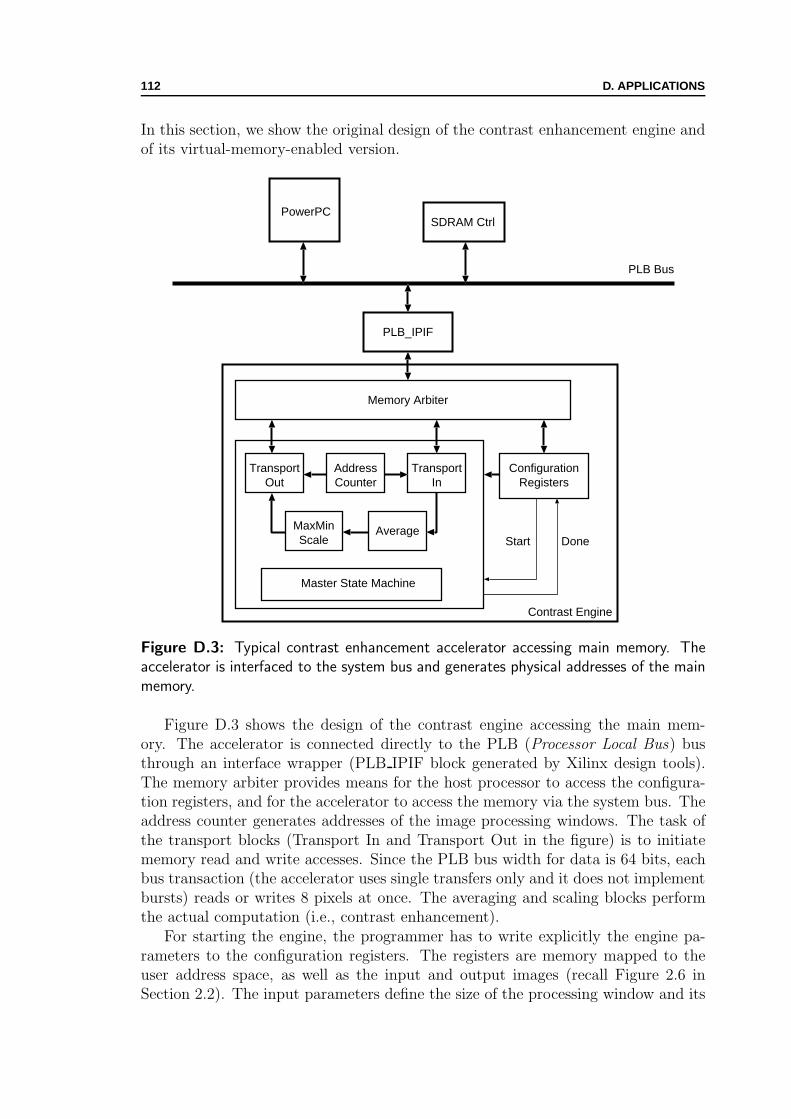
112 D. APPLICATIONS
In this section, we show the original design of the contrast enhancement engine andof its virtual-memory-enabled version.
PLB Bus
PowerPCSDRAM Ctrl
PLB_IPIF
Memory Arbiter
ConfigurationRegisters
TransportIn
TransportOut
AverageMaxMinScale
AddressCounter
Master State Machine
Contrast Engine
DoneStart
Figure D.3: Typical contrast enhancement accelerator accessing main memory. Theaccelerator is interfaced to the system bus and generates physical addresses of the mainmemory.
Figure D.3 shows the design of the contrast engine accessing the main mem-ory. The accelerator is connected directly to the PLB (Processor Local Bus) busthrough an interface wrapper (PLB IPIF block generated by Xilinx design tools).The memory arbiter provides means for the host processor to access the configura-tion registers, and for the accelerator to access the memory via the system bus. Theaddress counter generates addresses of the image processing windows. The task ofthe transport blocks (Transport In and Transport Out in the figure) is to initiatememory read and write accesses. Since the PLB bus width for data is 64 bits, eachbus transaction (the accelerator uses single transfers only and it does not implementbursts) reads or writes 8 pixels at once. The averaging and scaling blocks performthe actual computation (i.e., contrast enhancement).
For starting the engine, the programmer has to write explicitly the engine pa-rameters to the configuration registers. The registers are memory mapped to theuser address space, as well as the input and output images (recall Figure 2.6 inSection 2.2). The input parameters define the size of the processing window and its

D.2. CONTRAST ENGINE DESIGN 113
origin relative to the whole image (as Figure 5.2 illustrates). Once the computationhas started, the engine first samples a subwindow (its size is 6 times smaller thanthe processing window) to determine the internal thresholds for the main process-ing. Then, it performs the contrast enhancement by reading four input windowsand writing the output window in the result image. At the end, the acceleratorgenerates an interrupt and waits for the software to acknowledge it. The program-mer restarts the operation for processing another frame. The OS has to reservethe memory regions accessed by the accelerator at the system boot time. Process-ing another window would require copying to/from the reserved memory regionsor reserving more memory from the OS. The programming is much simplified forthe virtual-memory-enabled accelerators, where passing pointers to the dynamicmemory containing the images is sufficient.
Memory Arbiter
ConfigurationRegisters
TransportIn
TransportOut
AverageMaxMinScale
AddressCounter
Master State Machine
Contrast Engine
DoneStart
InitialisationController
WMU Interface
WMULocalMemory
OPB BusPLB Bus
Figure D.4: Virtual-memory-enabled contrast enhancement accelerator. The accelera-tor is interfaced to the local memory through the WMU. It accesses virtual memory ofthe user address space.
Figure D.4 shows the virtual-memory-enabled version of the contrast enhance-ment engine. Instead of using the Xilinx interface, the accelerator connects to thesystem through the WMU interface toward the local memory. We have changedthe original memory arbiter and added the initialisation controller. The rest of the

114 D. APPLICATIONS
accelerator is practically unchanged. When the programmer starts the acceleratorthrough the sys_hwacc system call, the engine reads the initialisation parametersthrough the WMU exchange registers and writes them to the configuration registers.Then, it launches the computation. The transport blocks now use virtual memoryaddresses to access the local memory through the WMU interface. There are noexplicit transfers over the system bus initiated by the accelerator. It is completelyhidden by the WMU interfaces, thus, platform-independent.
After synthesis of the accelerator (and the surrounding interfacing and systemsupport blocks—discussed in Appendix C), the engine could run at the frequency of100MHz on the Xilinx Virtex-II Pro device. The virtual-memory-enabled accelera-tors are connected to the local memory of 64KB. The spare reconfigurable logic ofthe device allows adding another accelerator to the system (with its own WMU in-terface and the local memory). We have used such system for running multithreadedexperiments, with the contrast enhancement and edge detection accelerators runningsimultaneously in the reconfigurable hardware.
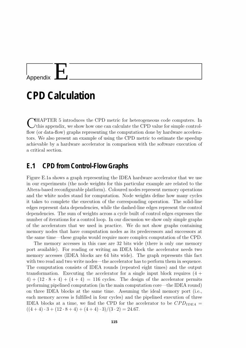
Appendix ECPD Calculation
CHAPTER 5 introduces the CPD metric for heterogeneous code computers. Inthis appendix, we show how one can calculate the CPD value for simple control-
flow (or data-flow) graphs representing the computation done by hardware accelera-tors. We also present an example of using the CPD metric to estimate the speedupachievable by a hardware accelerator in comparison with the software execution ofa critical section.
E.1 CPD from Control-Flow Graphs
Figure E.1a shows a graph representing the IDEA hardware accelerator that we usein our experiments (the node weights for this particular example are related to theAltera-based reconfigurable platform). Coloured nodes represent memory operationsand the white nodes stand for computation. Node weights define how many cyclesit takes to complete the execution of the corresponding operation. The solid-lineedges represent data dependencies, while the dashed-line edges represent the controldependencies. The sum of weights across a cycle built of control edges expresses thenumber of iterations for a control loop. In our discussion we show only simple graphsof the accelerators that we used in practice. We do not show graphs containingmemory nodes that have computation nodes as its predecessors and successors atthe same time—these graphs would require more complex computation of the CPD.
The memory accesses in this case are 32 bits wide (there is only one memoryport available). For reading or writing an IDEA block the accelerator needs twomemory accesses (IDEA blocks are 64 bits wide). The graph represents this factwith two read and two write nodes—the accelerator has to perform them in sequence.The computation consists of IDEA rounds (repeated eight times) and the outputtransformation. Executing the accelerator for a single input block requires (4 +4) + (12 · 8 + 4) + (4 + 4) = 116 cycles. The design of the accelerator permitspreforming pipelined computation (in the main computation core—the IDEA round)on three IDEA blocks at the same time. Assuming the ideal memory port (i.e.,each memory access is fulfilled in four cycles) and the pipelined execution of threeIDEA blocks at a time, we find the CPD for the accelerator to be CPDIDEA =((4 + 4) · 3 + (12 · 8 + 4) + (4 + 4) · 3)/(3 · 2) = 24.67.
115
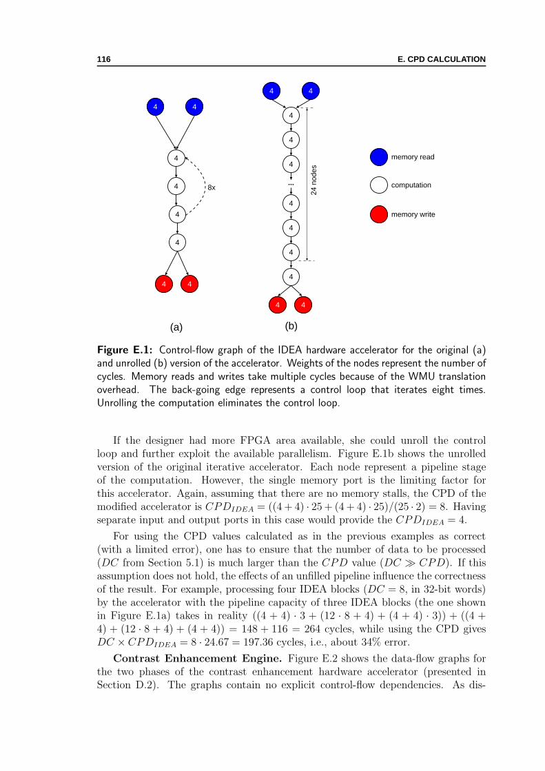
116 E. CPD CALCULATION
4
4 4
4
memory read
memory write
computation8x
4
4
4
4
4
4 4
44
4
4
...
4
4
4
4
24 n
odes
(a) (b)
Figure E.1: Control-flow graph of the IDEA hardware accelerator for the original (a)and unrolled (b) version of the accelerator. Weights of the nodes represent the number ofcycles. Memory reads and writes take multiple cycles because of the WMU translationoverhead. The back-going edge represents a control loop that iterates eight times.Unrolling the computation eliminates the control loop.
If the designer had more FPGA area available, she could unroll the controlloop and further exploit the available parallelism. Figure E.1b shows the unrolledversion of the original iterative accelerator. Each node represent a pipeline stageof the computation. However, the single memory port is the limiting factor forthis accelerator. Again, assuming that there are no memory stalls, the CPD of themodified accelerator is CPDIDEA = ((4 + 4) · 25 + (4 + 4) · 25)/(25 · 2) = 8. Havingseparate input and output ports in this case would provide the CPDIDEA = 4.
For using the CPD values calculated as in the previous examples as correct(with a limited error), one has to ensure that the number of data to be processed(DC from Section 5.1) is much larger than the CPD value (DC � CPD). If thisassumption does not hold, the effects of an unfilled pipeline influence the correctnessof the result. For example, processing four IDEA blocks (DC = 8, in 32-bit words)by the accelerator with the pipeline capacity of three IDEA blocks (the one shownin Figure E.1a) takes in reality ((4 + 4) · 3 + (12 · 8 + 4) + (4 + 4) · 3)) + ((4 +4) + (12 · 8 + 4) + (4 + 4)) = 148 + 116 = 264 cycles, while using the CPD givesDC × CPDIDEA = 8 · 24.67 = 197.36 cycles, i.e., about 34% error.
Contrast Enhancement Engine. Figure E.2 shows the data-flow graphs forthe two phases of the contrast enhancement hardware accelerator (presented inSection D.2). The graphs contain no explicit control-flow dependencies. As dis-

E.2. HARDWARE EXECUTION TIME 117
cussed in Appendix D, the computation of contrast enhancement consists of twophases. The phases are not pipelined. Assuming one memory port (64-bits wide inthe implementation on the Xilinx device) and no memory stalls, we find CPD1 =((6+6+6+6)+12)/(4·2) = 4.5 and CPD2 = ((6+6+6+6)+15+6)/(4·2) = 5.625.In the case with each input and output port having its own memory port we haveCPD1 = (6 + 12)/(4 · 2) = 2.25 and CPD2 = (6 + 15 + 6)/(4 · 2) = 2.625
6
15
6 6 6
6
memory read
memory write
computation
6
12
6 6 6
(a) (b)
Figure E.2: In the first phase (a), the accelerator samples input subwindows andproduces no output. In the second phase (b), the accelerator performs the contrastenhancement and produces the output window. Memory operations go through theWMU and take 6 cycles in this case (the WMU implementation on the Xilinx device).
E.2 Hardware Execution Time
The overall execution time of a hardware accelerator consists of the time spent insoftware activities to support the interfacing and of the time spent in hardwareexecution:
ETHW = IC ′ × CPI ′ × TCPU + CCHW × THW , (E.1)
where CCHW is the total number of cycles (cycle count of hardware clock periodsTHW —in the general case, THW is different from TCPU) needed by the accelerator toperform its computation. We use IC ′ and CPI ′ in the above equation to emphasisetheir difference from the corresponding quantities of Equation 5.1 (Section 5.1).
While Equation 5.1 implicitly accounts (through CPI) for time spent in systemhardware activities (such as branch prediction, instruction and data caching, mul-tiple issue [44, 56]) to support the software-only execution, Equation E.1 explicitlyshows (through IC ′ × CPI ′ × TCPU) the time spent —recalling the discussion inSection 2.2—in burdensome software activities (such as partitioning data, schedul-ing memory transfers) to support the interfacing. On the other side, Equation E.1implicitly accounts (through CCHW ) for the time spent in cumbersome hardwareactivities (such as managing buffers and burst accesses). In contrast to the sys-tem activities accounted in ETSW , the execution support activities in ETHW aredelegated to the user (i.e., the software programmer and the hardware designer).

118 E. CPD CALCULATION
Section 5.1 proposes a metric that clearly separates execution-support and pure-execution activities of hardware accelerators.
The CPI parameter gives an insight regarding the CPU architecture and or-ganisation, which is not the case with the CCHW figure. We can notice that thereis no instruction count for the hardware part of Equation E.1—there is only oneinstruction (i.e., the hardware accelerator itself), which does not change over theexecution of the application.
We use the CPD metric to derive another way of expressing the overall executiontime of the hardware accelerator1:
ETHW = HT + CT
= DC × CPDHW × THW + CCmem.stalls × THW , (E.2)
where CPDHW is the CPD value for the hardware accelerator assuming the idealmemory hierarchy (i.e., the memory accesses introduce no stalls) and, CCmem.stalls isthe number of cycles (cycle count) that the accelerator has to wait for the softwareor hardware action or, in other words2:
CCmem.stalls = Nmiss × Pmiss , (E.3)
with Nmiss being the number of times the accelerator has to wait for the transfersto the local memory, and Pmiss being the cost or penalty in cycles of such event. Weshall notice that Pmiss represents, in fact, the cycles spent in software for copying,or in hardware for accessing the main memory and filling local buffers with burstaccesses. We further develop Equation E.2 to obtain
ETHW = DC × CPDHW × THW + Nmiss × Pmiss × THW
= DC ×(CPDHW +
Nmiss
DC× Pmiss
)× THW
= DC × (CPDHW + Rmiss × Pmiss) × THW
= DC × (CPDHW + CPDmemory) × THW , (E.4)
where Rmiss is the miss rate, and CPDmemory represents overhead incurred by thememory transfers from the main memory to the local memory and vice versa or bythe direct accesses to the main memory (with and without bursts, as Section 2.2discusses).
The form of Equation E.4 is convenient for the hardware accelerators where wecannot easily separate the CT and HT components, but we can measure or calculateRmiss and Pmiss .
1We assume again that the management time is negligible, as well as execution transfers betweensoftware and hardware.
2A simplifying assumption here is that all memory transfers have the same cost, which holdsfor the accelerators with simple memory access patterns.

E.3. CRITICAL SECTION SPEEDUP 119
E.3 Critical Section Speedup
If we extend our general-purpose system with a hardware accelerator implementingthe critical code section and running within the codesigned application, the speedupachieved by the hardware accelerator is
Speedupcriticalsection =ETSW
ETHW, (E.5)
where ETHW is the overall execution time of the accelerator.A designer (or an automated design flow) who decides to move a critical section
from software to hardware may want to estimate the potential benefit first. In suchsituation, the CPD metric provides the means for the comparison. Here we showan example of its use. Recalling discussion from Chapter 5, for the speedup of thecritical section (moved from software to hardware execution), we can write:
Speedupcriticalsection =IC × CPI × TCPU
DC × CPDHW × THW
=DC × IC×CPI
DC× TCPU
DC × CPDHW × THW
=CPDSW × TCPU
CPDHW × THW
(E.6)
if we assume the same word size for software and hardware, when accessing thedata from memory. For instance, if we take an example of a code section originallyexecuted to process 2048 words on a single-issue pipelined CPU (running at 300MHz,thus TCPU = 3.33ns), with IC = 20000 and CPI = 1.05, we find CPDSW =(20000×1.05)/2048 = 10.25. On the other side, we have the corresponding hardwareaccelerator (accessing local memory as Figure 2.3 shows and running in FPGAat 100MHz, thus THW = 10ns) operating on the same data, with CPDHW =1.2. The CPD value close to 1 indicates a heavily-pipelined implementation of theaccelerator, capable of processing one datum per cycle (assuming ideal accesses tothe local memory that always take one cycle per access). In reality, the differenceof 0.2 from the ideal CPD value accounts for an average number of cycles spentfor hardware accelerator stalls and software activities to transfer the data from themain memory to the local memory—the average access time to the local memory inpractice is not equal to one cycle.
In this particular example, moving the critical section to hardware would achievetherefore a speedup of:
Speedup =10.25 × 3.33ns
1.2 × 10ns= 2.84 (E.7)

120 E. CPD CALCULATION

Appendix FMPEG4 Hardware Reference
THE Moving Picture Experts Group (MPEG) is a working group of the Inter-national Standardisation Organisation (ISO) responsible for the development
of international standards for compression, decompression, processing, and codedrepresentation of moving pictures, audio and their combination [85]. A commonway of describing outcoming MPEG standards is to use a reference code writtenin a high-level programming language (typically C programming language). Oneof the activities of the MPEG—within an ad-hoc group assigned to this task—isto develop a reference hardware description of the MPEG-4 algorithms written inthe VHDL hardware-description language. Historically, designers would develophardware accelerators for MPEG starting from the reference C code; having thereference description of the standard in VHDL would shortcut the design path fromthe software reference description to the accelerator hardware.
The reference hardware description group has developed a framework for plat-form-independent hardware accelerators called Virtual Sockets [97, 96]. One of theongoing activities of the group is to integrate our concept of unified virtual memoryfor software and hardware into the existing framework [77]. The integration (1)will allow user IPs to be completely unaware of physical location of the accesseddata and (2) there will be no need for the software programmer to do the explicitdata transfers between the main memory and the IPs. In this appendix, we brieflyshow the existing MPEG-4 framework for reference hardware design and presentthe application of our unified virtual memory to it.
F.1 Virtual Socket Framework
The University of Calgary [97] has developed Virtual Socket framework for theWildcard II reconfigurable PC card (shown in Figure F.1) from Annapolis MicroSystems [7]. The Wildcard II is an extension card for portable or wearable comput-ers. It contains a Virtex-II device (X2CV3000) from Xilinx [130], external SDRAM(64MB) and SRAM (2MB) memory, analog-to-digital converter, a multi-channelDMA controller, and digital input/output ports. The reconfigurable device intendedfor accelerating applications is connected to the host computer over the PC Cardbus (former PCMCIA interface).
121

122 F. MPEG4 HARDWARE REFERENCE
Figure F.1: Wildcard II reconfigurable PC Card from Annapolis Micro Systems. Thecard contains a Xilinx Virtex-II device, PC interfacing logic, and on-card memories.
Figure F.2 shows Virtual Socket framework. The framework provides platform-independent connections (virtual sockets) to multiple user IPs (hardware modulesimplementing some MPEG functionality). Each socket allows user IPs to access fourdifferent on-chip (within the Xilinx Virtex-II device, registers and BRAM space) andon-card (SDRAM and SRAM off the Virtex-II device) memory spaces. Regardingon-chip memories, Virtual Socket assigns to each IP its own memory slot. It is thetask of the programmer to control explicitly the IPs and copy the data from softwareto hardware. For example, if the data to be processed by the IP is larger than theavailable memory in the corresponding slot, the programmer has to partition thedata and schedule the transfers.
F.2 Virtual Memory Extension
The ongoing extensions of Virtual Socket framework have the goal to adapt theexisting framework and provide the virtual memory abstraction and shared addressspace for user software and hardware IPs. The burdensome task of data movementsis delegated to the system layer, thus, releasing the programmer. The virtual mem-ory extension mode is optional, meaning that MPEG hardware designers can decidewhether or not to use the extension. Since the unified memory abstraction facilitateshardware and software interfacing and partitioning, an appealing possibility for thedesigners is to use the virtual memory extension at the early stages of the moduledesign. During this phase, the system-level layer would provide memory-access pro-filing for a given hardware module. Later on, the obtained profile would be used

F.2. VIRTUAL MEMORY EXTENSION 123
Virtual DRAM Controller
FPGA
Virtual Register Controllerand Register Space
Virtual SRAM Controller
HW
InterfaceC
ontroller
IP0
...
SR
AM
DR
AM
LAD
Bus M
ux Interface
PC
I Card B
us Controller
Host S
ystem
IP1
IPn
InterruptMask
InterruptController Interrupt Resources
Virtual BRAM Controllerand BRAM Space
Figure F.2: Virtual Socket framework. The HW Interface Controller allows user IPblocks to access four different memory address spaces. The programmer explicitly trans-fers data from the host computer to these memories.
to tailor the system layer and optimise the memory transfers, thus minimising thevirtual memory overhead.
Figure F.3 shows the integration of the WMU within the existing framework.One of the design tasks was to keep the IP interface as close as possible to the originalVirtual Socket. To integrate the WMU, we have added an additional signal to theoriginal interface. The signal called Virt_mem_access (asserted by an IP accessingthe virtual memory) extends the interface and controls a switch box (shown inFigure F.3). During a virtual-memory access of the IP, the switch detours memoryread or write addresses and related control signals to the hardware translation unit—the WMU; in turn, for a successful translation, the WMU generates the physical pagenumber and passes it to the hardware interface controller of the original framework;finally, the controller performs the memory operation and returns the data from/tothe IP block. In the case of an unsuccessful translation, the WMU generates aninterrupt and the system software resolves its cause. For the moment, the WMUtranslates virtual memory accesses only to the BRAM address space. There is noslot limitation from the original framework.
The LAD bus connects the WMU directly to the host platform. Through theinterface, the VMW manager can access the control register, the status register,and the address registers of the WMU. In the case of an access fault, the addressregister contains the IP-generated address causing the interrupt. The VMW softwareis supposed to check this address, copy the requested data in the BRAM space ofthe Virtual Socket platform, and update the TLB through the LAD bus. Thevirtualisation layer screens the programmer and the hardware designer of theseevents.
The WMU generates another signal (Phys_page_num, an additional port of theHardware Interface Controller) acting as an input to the Hardware Interface Con-troller. The signal indicates the number of the page in the BRAM space where the
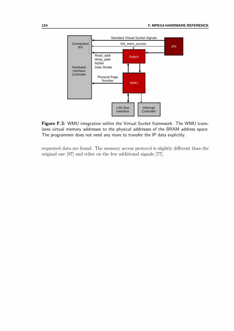
124 F. MPEG4 HARDWARE REFERENCE
HardwareInterfaceController
IP0Connection
IP0
WMU
Switch
LAD BusInterface
InterruptController
Virt_mem_access
Standard Virtual Socket Signals
Read_addrWrite_addrRd/WrData Strobe
Physical PageNumber
Figure F.3: WMU integration within the Virtual Socket framework. The WMU trans-lates virtual memory addresses to the physical addresses of the BRAM address space.The programmer does not need any more to transfer the IP data explicitly.
requested data are found. The memory access protocol is slightly different than theoriginal one [97] and relies on the few additional signals [77].
Bibliography
[1] Anant Agarwal, Ricardo Bianchini, David Chaiken, Kirk L. Johnson, David A.Kranz, John Kubiatowicz, Beng-Hong Lim, Kenneth Mackenzie, and DonaldYeung. The MIT Alewife machine: Architecture and performance. In Proceed-ings of the 22nd Annual International Symposium on Computer Architecture,pages 2–13, Santa Margherita Ligure, Italy, June 1995.
[2] Alfred V. Aho, Ravi Sethi, and Jeffrey D. Ullman. Compilers: Principles,Techniques, and Tools. Addison Wesley Longman, Inc., Boston, 1986.
[3] Altera Corporation. Excalibur Devices, November 2002. [Online; accessedvia http://www.altera.com/literature/manual/mnl arm hardware ref.pdf on10th December 2003].
[4] Don Anderson. Pentium Processor System Architecture. Mindshare Press,New York, 1994.
[5] Erik Anderson, Jason Agron, Wesley Peck, Jim Stevens, Fabrice Baijot,Ed Komp, and David Andrews. Enabling a uniform programming modelacross the software/hardware boundary. In Proceedings of the 14th IEEESymposium on Field-Programmable Custom Computing Machines, Napa Val-ley, Calif., April 2006.
[6] David Andrews, Douglas Niehaus, Razali Jidin, Michael Finley, Wesley Peck,Michael Frisbie, Jorge Ortiz, and Ed Komp. Programming models forhyprid FPGA-CPU computational components: A missing link. IEEE Mi-cro, 24(4):42–53, July 2004.
[7] Annapolis Micro Systems, Inc., Annapolis, Md. Wildcard-II ReferenceManual, 2004. [Online; accessed via http://www.annapmicro.com/manuals/
wcii manual v2 6.pdf on April 30th 2006].
[8] ARM Inc. AMBA Specification, 1999. [Online; accessed via http://www.arm.
com/products/solutions/AMBA Spec.html on 7th September 2006].
[9] ARM Inc. Application Binary Interface (ABI) for the ARM Architecture,2006. [Online; accessed via http://www.arm.com/products/DevTools/ABI.html
on 30th April 2006].
125

126 BIBLIOGRAPHY
[10] Peter M. Athanas and Harvey F. Silverman. Processor reconfiguration throughinstruction-set metamorphosis. Computer, 26(3):11–18, March 1993.
[11] Jonathan Babb, Martin Rinard, Csaba Andras Moritz, Walter Lee, MatthewFrank, Rajeev Barua, and Saman Amarasinghe. Parallelizing applications intosilicon. In Proceedings of the 7th IEEE Symposium on Field-ProgrammableCustom Computing Machines, pages 70–80, Napa Valley, Calif., April 1999.
[12] Maurice J. Bach. The Design of the UNIX Operating System. Prentice-Hall,Englewood Cliffs, N.J., 1986.
[13] Jean Bacon and Tim Harris. Operating Systems: Concurrent and DistributedSoftware Design. Addison-Wesley, Reading, Mass., 2003.
[14] Kavita Bala, M. Frans Kaashoek, and William E. Weihl. Software prefetch-ing and caching for translation lookaside buffers. In Proceedings of the FirstUSENIX Symposium on Operating Systems Design and Implementation, pages243–53, Monterey, Calif., November 1994.
[15] Gregory A. Baxes. Digital Image Processing: Principles and Applications.Wiley, New York, 1994.
[16] John K. Bennett, John B. Carter, and Willy Zwaenepoel. Adaptive softwarecache management for distributed shared memory architectures. In Proceed-ings of the 17th Annual International Symposium on Computer Architecture,pages 125–34, Seattle, Wash., June 1990.
[17] Jean-Luc Beuchat. Modular multiplication for FPGA implementation of theIDEA block cipher. In Proceedings of the 14th International Conference onApplication-specific Systems, Architectures and Processors, pages 412–22, TheHague, Netherlands, June 2003.
[18] Mattias A. Blumrich, Kai Li, Richard Alpert, Cezary Dubnicki, Edward W.Felten, and Jonathan Sandberg. Virtual memory mapped network interface forthe SHRIMP multicomputer. In Proceedings of the 21st Annual InternationalSymposium on Computer Architecture, pages 142–53, Chicago, Ill., April 1994.
[19] Daniel P. Bovet and Marco Cesati. Understanding the Linux Kernel. O’ReillyMedia, Inc., Sebastopol, Calif., second edition, 2002.
[20] Gordon Brebner. A virtual hardware operating system for the Xilinx XC6200.In Proceedings of the 6th International Workshop on Field-ProgrammableLogic and Applications, pages 327–36, Darmstadt, Germany, September 1996.
[21] Gordon Brebner. The swappable logic unit: a paradigm for virtual hardware.In Proceedings of the 5th IEEE Symposium on Field-Programmable CustomComputing Machines, pages 77–86, Napa Valley, Calif., April 1997.

BIBLIOGRAPHY 127
[22] Gordon Brebner, Phil James-Roxby, and Chidamber Kulkarni. Hyper-programmable architecture for adaptable networked systems. In Proceedingsof the 15th International Conference on Application-specific Systems, Archi-tectures and Processors, pages 328–38, Galveston, Tex., September 2004.
[23] Mihai Budiu, Girish Venkataramani, Tiberiu Chelcea, and Seth Copen Gold-stein. Spatial computation. In Proceedings of the 11th International Con-ference on Architectural Support for Programming Languages and OperatingSystems, pages 14–26, Boston, Mass., October 2004.
[24] Doug Burger and Todd M. Austin. The SimpleScalar tool set, version 2.0.Computer Architure News, 25(3):13–25, June 1997.
[25] Timothy J. Callahan, John R. Hauser, and John Wawrzynek. The Garp ar-chitecture and C compiler. Computer, 33(4):62–69, April 2000.
[26] Eylon Caspi, Michael Chu, Randy Huang, Joseph Yeh, Andre DeHon, andJohn Wawrzynek. Stream computations organized for reconfigurable execution(SCORE): Introduction and tutorial. In Proceedings of the 10th InternationalConference on Field-Programmable Logic and Applications, pages 605–14, Vil-lach, Austria, August 2000.
[27] Eylon Caspi, Andre Dehon, and John Wawrzynek. A streaming multi-threadedmodel. In In Proceedings of the Third Workshop on Media and Stream Pro-cessors, pages 21–28, Austin, Tex., December 2001.
[28] Francky Catthoor, Sven Wuytack, Eddy De Greef, Florin Balasa, LodeNachtergaele, and Arnout Vandecapelle. Custom Memory ManagementMethodology. Kluwer Academic, Boston, Mass., 1998.
[29] Celoxica Ltd. Handel-C Language Reference Manual, 2004. [Online;accessed via http://www.celoxica.com/techlib/files/CEL-W0410251JJ4-60.
pdf on 7th September 2006].
[30] Celoxica Ltd., Oxfordshire, UK. Data Streaming Manager (Datasheet),2005. [Online; accessed via http://www.celoxica.com/techlib/files/
CEL-W0506201CG6-46.pdf on 7th September 2006].
[31] Thomas H. Cormen, Charles E. Leiserson, Ronald L. Rivest, and CliffordStein. Introduction to Algorithms. MIT Press, Cambridge, Mass., secondedition, 2001.
[32] Ingmar Cramm. Entwicklung und implementierung einer EdgeEngine zurerkennung von kanten in zukunftigen fahrerassistenzsystemen. Master the-sis, Technische Universitat Munchen, Munich, May 2006.
[33] David E. Culler, Jaswinder Pal Singh, and Anoop Gupta. Parallel ComputerArchitecture: A Hardware/Software Approach. Morgan Kaufmann, San Ma-teo, Calif., 1999.

128 BIBLIOGRAPHY
[34] Michael Dales. Managing a reconfigurable processor in a general purposeworkstation environment. In Proceedings of the Design, Automation and Testin Europe Conference and Exhibition, pages 10980–85, Munich, March 2003.
[35] Giovanni De Micheli. Synthesis and Optimization of Digital Circuits. McGraw-Hill, New York, 1994.
[36] Giovanni De Micheli. Hardware synthesis from C/C++ models. In Proceedingsof the Design, Automation and Test in Europe Conference and Exhibition,pages 382–83, Munich, March 1999.
[37] Giovanni De Micheli, Rolf Ernst, and Wayne Wolf. Readings in Hardware/-Software Co-design. Kluwer Academic, Boston, Mass., 2002.
[38] Andre DeHon. The density advantage of configurable computing. Computer,33(4):41–49, April 2000.
[39] Christophe Dubach. Java bytecode synthesis for reconfigurable computingplatforms. Master thesis, Ecole Polytechnique Federale de Lausanne (EPFL),January 2005.
[40] Stephen A. Edwards. The challenges of hardware synthesis from C-like lan-guages. In Proceedings of the Design, Automation and Test in Europe Con-ference and Exhibition, pages 66–67, Munich, March 2005.
[41] Joseph A. Fisher, Paolo Faraboschi, and Clifford Young. Embedded Com-puting: a VLIW Approach to Architecture, Compilers and Tools. MorganKaufmann Publishers Inc., San Francisco, 2004.
[42] B. Flachs, S. Asano, S.H. Dhong, P. Hotstee, G. Gervais, R. Kim, T. Le,P. Liu, J. Leenstra, J. Liberty, B. Michael, H. Oh, S.M. Mueller, O. Takahashi,A. Hatakeyama, Y. Watanabe, and N. Yano. A streaming processing unit fora CELL processor. In IEEE International Solid-State Circuits Conference,Digest of Technical Papers, pages 134–35, San Francisco, February 2005.
[43] Josef Fleischmann, Klaus Buchenrieder, and Rainer Kress. Java driven code-sign and prototyping of networked embedded systems. In Proceedings of the36th Design Automation Conference, pages 794–97, New Orleans, La., June1999.
[44] Michael J. Flynn. Computer Architecture—Pipelined and Parallel ProcessorDesign. Jones and Bartlett, Boston, Mass., 1995.
[45] Wenyin Fu and Katherine Compton. An execution environment for reconfig-urable computing. In Proceedings of the 13th IEEE Symposium on Field-Programmable Custom Computing Machines, pages 149–58, Napa Valley,Calif., April 2005.
BIBLIOGRAPHY 129
[46] Daniel Gajski, Jianwen Zhu, Rainer Domer, Andreas Gerstlauer, and ShuqingZhao. SpecC: Specification Language and Design Methodology. Springer,Berlin, 2000.
[47] D. Galloway. The Transmogrifier C hardware description language and com-piler for FPGAs. In Proceedings of the 3rd IEEE Symposium on Field-Programmable Custom Computing Machines, pages 136–44, Napa Valley,Calif., April 1995.
[48] Cedric Gaudin. Module SOC/ARM sur FPGA. Master thesis, Ecole Poly-technique Federale de Lausanne (EPFL), February 2003.
[49] Ferid Gharsalli, Samy Meftali, Frederic Rousseau, and Ahmed A. Jerraya.Automatic generation of embedded memory wrapper for multiprocessor SoC.In Proceedings of the 39th Design Automation Conference, pages 596–601, NewOrleans, La., June 2002.
[50] J. C. Gibson. The Gibson mix. Technical Report TR.00.2043, InternationalBusiness Machines, Inc., Poughkeepsie, N.Y., June 1970.
[51] Maya Gokhale and Paul S. Graham. Reconfigurable Computing: AcceleratingComputation with Field-Programmable Gate Arrays. Springer, Berlin, 2005.
[52] Sven A. Gowal. Operating system support for multithreaded reconfigurablehardware. Internship project, Ecole Polytechnique Federale de Lausanne(EPFL), September 2005.
[53] Thorsten Grotker, Stan Liao, Grant Martin, and Stuart Swan. System Designwith SystemC. Kluwer Academic Publishers, Norwell, Mass., 2002.
[54] Tom R. Halfhill. New patent reveals Cell secrets. Microprocessor Report,3 January 2005.
[55] John R. Hauser and John Wawrzynek. Garp: A MIPS processor with a recon-figurable coprocessor. In Proceedings of the 5th IEEE Symposium on Field-Programmable Custom Computing Machines, pages 12–21, Napa Valley, Calif.,April 1997.
[56] John L. Hennessy and David A. Patterson. Computer Architecture: A Quan-titative Approach. Morgan Kaufmann, San Mateo, Calif., third edition, 2002.
[57] Michael Herz, Reiner Hartenstein, Miguel Miranda, Erik Brockmeyer, andFrancky Catthoor. Memory addressing organisation for stream-based recon-figurable computing. In Proceedings of the 9th IEEE International Conferenceon Electronics, Circuits and Systems, Dubrovnik, Croatia, September 2002.
[58] Paolo Ienne and Rainer Leupers, editors. Customizable Embedded Processors:Design Technologies & Applications. Systems on Silicon Series. Morgan Kauf-mann, San Mateo, Calif., 2006.
130 BIBLIOGRAPHY
[59] International Business Machines, Inc. The CoreConnect Bus Architecture,2006. [Online; accessed via http://www-306.ibm.com/chips/techlib/techlib.
nsf/productfamilies/CoreConnect Bus Architecture/ on 7th September2006].
[60] Ayal Itzkovitz and Assaf Schuster. Distributed shared memory: Bridging thegranularity gap. In Proceedings of the 1st Workshop on Software DistributedShared Memory (WSDSM’99), Rhodes, Greece, June 1999.
[61] Cedric Jeannaret. Synthesising Java bytecode to hardware. Semester project,Ecole Polytechnique Federale de Lausanne (EPFL), February 2006.
[62] Java Native Interface specification, 2003. [Online; accessed via http://java.
sun.com/j2se/1.4.2/docs/guide/jni/ on 7th September 2006].
[63] Norman P. Jouppi. Improving direct-mapped cache performance by the addi-tion of a small fully-associative cache and prefetch buffers. In Proceedings ofthe 17th Annual International Symposium on Computer Architecture, pages364–73, Seattle, Wash., May 1990.
[64] Kaffe is not Java, 2006. [Online; accessed via http://www.kaffe.org/ on 30thApril 2006].
[65] Kevin Krewell. Cell moves into the limelight. Microprocessor Report, 14 Febru-ary 2005.
[66] Holger Lange and Andreas Koch. Memory access schemes for configurableprocessors. In Proceedings of the 10th International Conference on Field-Programmable Logic and Applications, pages 615–25, Villach, Austria, August2000.
[67] Emanuele Lattanzi, Aman Gayasen, Mahmuth Kandemir, VijaykrishnanNarayanan, Luca Benini, and Alessandro Bogliolo. Improving Java perfor-mance by dynamic method migration on FPGAs. In Proceedings of the 11thReconfigurable Architectures Workshop, pages 134–141, Santa Fe, N. Mex.,April 2004.
[68] Chunho Lee, Miodrag Potkonjak, and William H. Mangione-Smith. Media-Bench: A tool for evaluating and synthesizing multimedia and communicatonssystems. In Proceedings of the 30th Annual International Symposium on Mi-croarchitecture, pages 330–35, Research Triangle Park, N.C., December 1997.
[69] Tien-Lung Lee and Neil W. Bergmann. An interface methodology for retar-getable FPGA peripherals. In Proceedings of the 3rd International Conferenceon Engineering of Reconfigurable Systems and Algorithms (ERSA), pages 167–73, Las Vegas, Nev., June 2003.
[70] Marc Leeman, David Atienza, Chantal Ykman, Francky Catthoor,Jose Manuel Mendias, and Geert Deconcinck. Methodology for refinement
BIBLIOGRAPHY 131
and optimization of dynamic memory management for embedded systems inmultimedia applications. In IEEE Workshop on Signal Processing Systems,Seoul, Korea, August 2003.
[71] Christopher K. Lennard, Patrick Schaumont, Gjalt De Jong, Anssi Haverinen,and Pete Hardee. Standards for system-level design: Practical reality or so-lution in search of a question? In Proceedings of the Design, Automation andTest in Europe Conference and Exhibition, pages 576–83, Paris, March 2000.
[72] P.H.W. Leong, M.P. Leong, O.Y.H Cheung, T. Tung, C.M. Kwok, M.Y.Wong, and K.H Lee. Pilchard—a reconfigurable computing platform withmemory slot interface. In Proceedings of the 9th IEEE Symposium on Field-Programmable Custom Computing Machines, pages 170–70, Napa Valley,Calif., April 2001.
[73] Markus Levy. Java to go: The finale. Microprocessor Report, 4 June 2001.
[74] Kai Li. IVY: A shared virtual memory system for parallel computing. InProceedings of the 1988 International Conference on Parallel Processing, pages94–101, The Pennsylvania State University, University Part, Penn., August1988.
[75] The Linux kernel archives. http://www.kernel.org/, 2006.
[76] Robert Love. Linux Kernel Development. Novell Press, Waltham, Mass.,second edition, 2005.
[77] Adding virtual memory support to MPEG4 hardware reference platform,April 2006. MPEG4-Part9 ISO/IEC JTC1/SC29/WG11 M13117, Montreux,Switzerland.
[78] Damien Lyonnard, Sungjoo Yoo, Amer Baghdadi, and Ahmed A. Jerraya.Automatic generation of application-specific architectures for heterogeneousmultiprocessor system-on-chip. In Proceedings of the 38th Design AutomationConference, pages 518–23, Las Vegas, Nev., June 2001.
[79] Roman Lysecky, Frank Vahid, and Sheldon X.-D. Tan. Dynamic FPGA rout-ing for just-in-time FPGA compilation. In Proceedings of the 41st DesignAutomation Conference, pages 954–59, San Diego, Calif., June 2004.
[80] Evangelos P. Markatos and Manolis G. H. Katevenis. User-level DMA withoutoperating system kernel modification. In Proceedings of the 3rd InternationalSymposium on High-Performance Computer Architecture, pages 322–31, SanAntonio, Tex., February 1997.
[81] Cathy May, Ed Silha, Rick Simpson, and Hank Warren, editors. The PowerPCArchitecture: A Specification for a New Family of RISC Processors. MorganKaufmann Publishers Inc., San Francisco, 1994.
132 BIBLIOGRAPHY
[82] MediaCrypt. IDEA Algorithm, 2003. [Online; accessed via http://www.
mediacrypt.com/ pdf/IDEA Technical Description 0105.pdf on 7th Septem-ber 2006].
[83] Chad L. Mitchell and Michael J. Flynn. A workbench for computer architects.IEEE Design and Test of Computers, 5(1):19–29, January–February 1988.
[84] Overview of MPEG-4 Part-9 reference HW description. http://www.
chiariglione.org/MPEG/technologies/mp04-hrd/, October 2005. Interna-tional Organisation for Standardisation.
[85] MPEG: Moving pictures experts group. http://www.chiariglione.org/mpeg/,2006. International Organisation for Standardisation.
[86] Shubhendu S. Mukherjee, Babak Falsafi, Mark D. Hill, and David A. Wood.Coherent network interfaces for fine-grain communication. In Proceedings ofthe 23rd Annual International Symposium on Computer Architecture, pages247–58, Philadelphia, Penn., 1996.
[87] Shubhendu S. Mukherjee and Mark D. Hill. Making network interfaces lessperipheral. Computer, 31(10):70–6, October 1998.
[88] Bradford Nichols. Pthreads Programming: A POSIX Standard for Better Mul-tiprocessing. O’Reilly and Associates, Sebastopol, Calif., 1996.
[89] Vincent Nollet, Paul Coene, Diederik Verkest, Serge Vernalde, and RudyLauwereins. Designing an operating system for a heterogeneous reconfigurableSoC. In Reconfigurable Architectures Workshop (RAW), Proceedings of the In-ternational Parallel and Distributed Processing Symposium, Paris, June 2003.
[90] Subbarao Palacharla and Richard E. Kessler. Evaluating stream buffers as asecondary cache replacement. In Proceedings of the 21st Annual InternationalSymposium on Computer Architecture, pages 24–33, Chicago, Ill., April 1994.
[91] Preeti Ranjan Panda, Nikil Dutt, and Alexandru Nicolau. Memory Issues inEmbedded Systems-on-Chip. Kluwer Academic, Boston, Mass., 1999.
[92] David Pellerin and Scott Thibault. Practical FPGA programming in C.Prentice-Hall, Englewood Cliffs, N.J., 2005.
[93] Karin Petersen and Kai Li. Multiprocessor cache coherence based on virtualmemory support. Journal of Parallel and Distributed Computing, 29(2):158–78, September 1995.
[94] D. Pham, S. Asano, M. Bolliger, M.N. Day, H.P. Hofstee, C. Johns, J. Kahle,A. Kameyama, J. Keaty, Y. Masubuchi, M. Riley, D. Shippy, D. Stasiak,M. Suzuoki, M. Wang, J. Warnock, S. Weitzel, D. Wendel, T. Yamazaki,and K. Yazawa. The design and implementation of a first-generation CELLprocessor. In IEEE International Solid-State Circuits Conference, Digest ofTechnical Papers, pages 184–85,592, San Francisco, February 2005.

BIBLIOGRAPHY 133
[95] Jelica Protic, Milo Tomasevic, and Veljko Milutinovic, editors. DistributedShared Memory: Concepts and Systems. IEEE Computer Society Press, LosAlamitos, Calif., 1997.
[96] Reference for virtual socket API function calls, January 2006. MPEG4-Part9ISO/IEC JTC1/SC29/WG11 M12788, Bangkok, Thailand.
[97] Tutorial on an integrated virtual socket hardware-accelerated co-design plat-form, January 2006. MPEG4-Part9 ISO/IEC JTC1/SC29/WG11 M12789,Bangkok, Thailand.
[98] Rahul Razdan and Michael D. Smith. A high-performance microarchitecturewith hardware-programmable functional units. In Proceedings of the 27thInternational Symposium on Microarchitecture, pages 172–80, San Jose, Calif.,November 1994.
[99] Amir Roth, Andreas Moshovos, and Gurindar S. Sohi. Dependence basedprefetching for linked data structures. In Proceedings of the 8th InternationalConference on Architectural Support for Programming Languages and Operat-ing Systems, pages 115–26, San Jose, Calif., October 1998.
[100] Radu Rugina and Martin Rinard. Span: a shape and pointer analysis pack-age. Technical Report TM-581, Massachusetts Institute of Technology, Boston,Mass., June 1998.
[101] John E. Savage. The performance of multilective VLSI algorithms. Journalof Computer and System Sciences, 29(2):243–73, October 1984.
[102] John E. Savage. Models of Computation: Exploring the Power of Computing.Addison Wesley Longman, Inc., Reading, Mass., 1998.
[103] Ioannis Schoinas and Mark D. Hill. Address translation mechanisms in net-work interfaces. In Proceedings of the 4th International Symposium on High-Performance Computer Architecture, pages 219–30, Las Vegas, Nev., February1998.
[104] Michael L. Scott. Programming Language Pragmatics. Morgan KaufmannPublishers Inc., San Francisco, second edition, 2005.
[105] David Seal. ARM Architecture Reference Manual. Addison-Wesley LongmanPublishing Co., Inc., Boston, Mass., 2000.
[106] Luc Semeria, Koichi Sato, and Giovanni De Micheli. Synthesis of hardwaremodels in C with pointers and complex data structures. IEEE Transactionson Very Large Scale Integration (VLSI) Systems, VLSI-9(6):743–56, December2001.
[107] Richard L. Sites and Richard L. Witek, editors. Alpha AXP ArchitectureReference Manual. Digital Press, Bedford, Mass., second edition, 1995.
134 BIBLIOGRAPHY
[108] Donald Soderman and Yuri Panchul. Implementing C algorithms in reconfig-urable hardware using C2Verilog. In Proceedings of the 6th IEEE Symposiumon Field-Programmable Custom Computing Machines, pages 339–42, NapaValley, Calif., April 1998.
[109] Yan Solihin, Jaejin Lee, and Josep Torrellas. Using a user-level memory threadfor correlation prefetching. In Proceedings of the 29th Annual InternationalSymposium on Computer Architecture, pages 171–82, Anchorage, Ala., May2002.
[110] William Stallings. Operating Systems: Internals and Design Principles. Pren-tice Hall, Upper Saddle River, N.J., 2005.
[111] Walter Stechele. Video processing using reconfigurable hardware accelerationfor driver assistance. In Workshop on Future Trends in Automotive Electronicsand Tool Integration at DATE 2006, Munich, March 2006.
[112] Walter Stechele, Alvado L. Carcel, Stephan Herrmann, and J.Lidon Simon. Acoprocessor for accelerating visual information processing. In Proceedings ofthe Design, Automation and Test in Europe Conference and Exhibition, pages26–31, Munich, March 2005.
[113] Stefan Steinke, Lars Wehmeyer, Bo-Sik Lee, and Peter Marwedel. Assigningprogram and data objects to scratchpad for energy reduction. In Proceedingsof the Design, Automation and Test in Europe Conference and Exhibition,Paris, March 2002.
[114] Chris Sullivan and Milan Saini. Software-compiled system design optimizesXilinx programmable systems. Xcell Journal, (46):32–37, Summer 2003.
[115] Sun Microsystems. The Java HotSpot Virtual Machine (White Paper), 2002.[Online; accessed via http://java.sun.com/javase/technologies/hotspot.
jsp on 7th September 2006].
[116] Andrew S. Tanenbaum. Modern Operating Systems. Prentice-Hall, Inc., UpperSaddle River, N.J., second edition, 2001.
[117] Uresh Vahalia. UNIX Internals: The New Frontiers. Prentice-Hall, EnglewoodCliffs, N.J., 1995.
[118] Stamatis Vassiliadis, Stephan Wong, Georgi Gaydadjiev, Koen Bertels, GeorgiKuzmanov, and Elena Moscu Panainte. The MOLEN polymorphic processor.IEEE Transactions on Computers, C-53(11):1363–75, November 2004.
[119] Miljan Vuletic, Christophe Dubach, Laura Pozzi, and Paolo Ienne. Enablingunrestricted automated synthesis of portable hardware accelerators for virtualmachines. In Proceedings of the International Conference on Hardware/Soft-ware Codesign and System Synthesis, pages 243–48, Jersey City, N.J., Septem-ber 2005.
BIBLIOGRAPHY 135
[120] Miljan Vuletic, Laura Pozzi, and Paolo Ienne. Dynamic prefetching in thevirtual memory window of portable reconfigurable coprocessors. In Proceed-ings of the 14th International Conference on Field-Programmable Logic andApplications, pages 596–605, Antwerp, Belgium, August 2004.
[121] Miljan Vuletic, Laura Pozzi, and Paolo Ienne. Virtual memory window fora portable reconfigurable cryptography coprocessor. In Proceedings of the12th IEEE Symposium on Field-Programmable Custom Computing Machines,pages 24–33, Napa Valley, Calif., April 2004.
[122] Miljan Vuletic, Laura Pozzi, and Paolo Ienne. Seamless hardware-softwareintegration in reconfigurable computing systems. IEEE Design and Test ofComputers, 22(2):102–13, March–April 2005.
[123] Herbert Walder and Marco Platzner. Online scheduling for block-partitionedreconfigurable devices. In Proceedings of the Design, Automation and Test inEurope Conference and Exhibition, pages 10290–95, Munich, March 2003.
[124] Jian Wang. An FPGA based software/hardware codesign for real time videoprocessing. Diploma Thesis LITH-ISY-EX–06/3756–SE, Linkoping University,Linkoping, Sweden, March 2006.
[125] Wikipedia. Application binary interface — Wikipedia, the free encyclopedia,2006. [Online; accessed on 30th April 2006].
[126] Wikipedia. System software — Wikipedia, the free encyclopedia, 2006. [On-line; accessed on 10th April 2006].
[127] R. Wilson, C. French, C. Wilson, J. Amarasinghe, J. Anderson, S. Tjiang, S.-W. Liao, M. Tseng, Hall, M. Lam, and J. Hennessy. SUIF: An infrastructurefor research on parallelizing and optimizing compilers. SIGPLAN Notices,29:31–37, December 1994.
[128] Wayne Wolf. Computers as Components: Principles of Embedded ComputerSystems Design. Morgan Kaufmann, San Mateo, Calif., 2001.
[129] Sven Wuytack, Julio L. da Silva Jr., Francky Catthoor, Gjalt de Jong, andChantal Ykman-Couvreur. Memory management for embedded network appli-cations. IEEE Transactions on Computer-Aided Design of Integrated Circuitsand Systems, CAD-18(5):533–44, May 1999.
[130] Xilinx Inc. Virtex-II Pro and Virtex-II Pro X User Guide, March 2005. [On-line; accessed via http://direct.xilinx.com/bvdocs/userguides/ug012.pdf
on 10th December 2005].
[131] A. Yamada, K. Nishida, R. Sakurai, A. Kay, and T. Nomura, T.and Kambe.Hardware synthesis with the Bach system. In Proceedings of the IEEE Interna-tional Symposium on Circuits and Systems, volume 6, pages 366–69, Orlando,Fla., May–June 1999.
136 BIBLIOGRAPHY
[132] Zhi Alex Ye, Andreas Moshovos, Scott Hauck, and Prithviraj Banerjee. CHI-MAERA: A high-performance architecture with a tightly-coupled reconfig-urable functional unit. In Proceedings of the 27th Annual International Sym-posium on Computer Architecture, pages 225–35, Vancouver, June 2000.
[133] Albert Y. Zomaya, editor. Handbook of Nature-Inspired and Innovative Com-puting: Integrating Classical Models with Emerging Technologies. Springer,Berlin, 2006.
[134] Steve. Zucker and Kari Karhi. System V application binary interface: Pow-erPC processor supplement. Technical Report 802-3334-10, Sun Microsystems,Inc., Mountain View, Calif., September 1995.

Curriculum Vitae
VULETIC MILJAN
PERSONAL DATA
Date of birth: December 10, 1971Place of birth: Zrenjanin, Vojvodina, Yugoslavia
Citizenship: Serbia
RESEARCH INTERESTS
Reconfigurable computing systems, OS support for heterogeneous and reconfigurable comput-ing, dynamic and partial reconfiguration, distributed shared-memory for reconfigurable computing,platform-independent hardware accelerators for multimedia applications, synthesis of high-levellanguages to hardware, instruction set specialisation for embedded processors.
EDUCATION
Jan 2001–Aug 2006 Ph.D. in Computer Engineering, Processor ArchitectureLaboratory (LAP), School of Computer and Communication Sciences,EPFL, Lausanne, Switzerland. Thesis title: Unifying Softwareand Hardware of Multithreaded Reconfigurable Applicationswithin Operating System Processes. Advisor: prof. Paolo Ienne.
Mar 1997–Mar 1999 M.S. Graduate School, School of Electrical Engineering,University of Belgrade, Serbia, Master project doneand graduate exams passed, but thesis defense never scheduled(because of political turmoils in former Yugoslavia).GPA: 10.00/10.00. Project title: Suboptimal Detection of TelemetrySignals: Functional Simulation and VLSI Implementation.Advisor: prof. Veljko Milutinovic.
Oct 1990–Feb 1997 Dipl.Ing. in Electrical Engineering, major in Computer Scienceand Engineering, School of Electrical Engineering,University of Belgrade. GPA: 8.93/10.00.
EMPLOYMENT
Jan 2001–present Research and Teaching Assistant, Processor ArchitectureLaboratory, School of Computer and Communication Sciences,EPFL, Lausanne, Switzerland.
Oct 1997–Oct 1998 Teaching Assistant (part-time), Computer Science and EngineeringDepartment, University of Belgrade, Serbia.
Jul 1994–Dec 2000 Chief System Engineer, OpenNet Internet provider (the firstInternet provider in Yugoslavia), Radio B92, Serbia.
137
138 Curriculum Vitae
RESEARCH EXPERIENCE
Graduate Research Assistant (2001–present) to prof. Paolo Ienne, Processor Archi-tecture Laboratory, School of Computer and Communication Sciences, EPFL, Lausanne, Switzer-land. Research activities:
• Investigated graph-based methods for identification of instruction set extensions.• Proposed a seamless integration of software and hardware in reconfigurable computing sys-
tems based on the extensions in system software and system hardware.• Proposed OS-based dynamic optimisation techniques to screen users (software programmers
and hardware designers) from memory-copy latencies in reconfigurable computing systems.
• Supervised the development of a synthesis flow, from a high-level programming language toreconfigurable hardware.
Research Assistant (1997–2000) to prof. Veljko Milutinovic, Department of ComputerScience and Engineering, School of Electrical Engineering, University of Belgrade, Serbia. Researchactivities:
• Proposed a low-quantisation method for detecting telemetry signals and suggested a detectorimplementation in VLSI.
• Investigated the application of low-quantisation detection methods to power measurement.
TEACHING EXPERIENCE
Teaching Assistant (2001–present) to prof. Paolo Ienne, Processor Architecture Labo-ratory, School of Computer and Communication Sciences, EPFL, Computer Architecture I and II,2nd and 3rd year undergraduate courses. As a part of teaching activities but within the researchscope, led about 20 students during their diploma, semester, and internship projects.
Teaching Assistant (1997–1998) to prof. Veljko Milutinovic, Department of Com-puter Science and Engineering, School of Electrical Engineering, University of Belgrade, Serbia,Computer VLSI Systems, 5th year undergraduate course.
PROFESSIONAL EXPERIENCE
Member of a VLSI engineering team (Jun 1996–Dec 1996), implementing R2 signal-ization (analog telephony switching protocol) on an FPGA-based detection board.
Design engineer (May 1997–Dec 1997), involved in a research project for eT Communi-cations, in the field of VLSI and ASIC design for telemetry applications.
Research analyst (May 1998 - September 1998) for eT Communications in the field ofVLSI for solid state power meter design.
Engineering-team leader (Spring 1998), American Center Internet Classrooms, developedspecialized software solution for public Internet classrooms (Belgrade, Podgorica), the project inassociation with the USA Information center.
Engineering-team leader (Fall 1998), realization of VPN (Virtual Private Network) se-cure network project, in cooperation with XS4ALL Netherlands Internet provider, employing andcustomizing VPN technologies.
Principal software engineer (Jul 1999–Dec 1999), design and implementation of anautomatic application generator from a database model (Borland Delphi code generator, based onthe Oracle Designer 2000 model).
Software architect (May 2000), analysis, modeling and programming for the informationsystem development of the Montenegro national airline company (Montenegro Airlines).

Vuletic Miljan 139
AWARDS, FELLOWSHIPS, HONORS
2001 Research assistantship from Infineon, Munich, Germany1997–2000 Research fellowship from the Ministry of Education, Serbia1997 First (out of aprox. 200) on the graduate enrollment list of School
of Electrical Engineering, University of Belgrade, Serbia
PROFESSIONAL ACTIVITIES
Reviewer for Design Automation Conference (DAC 2003), International Conference on Com-puter Aided Design (ICCAD 2004), Asynchronous Circuits and Systems (ASYNC 2006), Design,Automation, and Test in Europe (DATE 2006). Participating in the work of the hardware ref-erence implementation group (ISG) of the MPEG (a working group of ISO/IEC in charge of thedevelopment of international audio/video standards).
PROFESSIONAL SOCIETIES
Member of the ACM and IEEE (including IEEE Computer Society membership).
SKILLS
Programming languages: C/C++, Java, PHP, awk, perl, bash, Pascal, FORTRAN, Lisp,Basic, assembler (PDP-11, Z80, X86, MIPS, ARM). Hardware description languages: VHDL,Verilog, ISP’. Operating systems: FreeBSD, Linux and Digital Unix—advanced administrator,kernel and user programmer; Windows—administrator and user programmer, VAX—advanceduser. EDA tools: ModelSim, HDL Designer, Synplify, Leonardo, Quartus (Altera), Xilinx ISEand Platform Studio.
LANGUAGES
Serbian (native), English (fluent, spoken and written), French (fluent, spoken and written),Italian and German (rudimentary communication and understanding).
MISCELLANEOUS
Music (classic and jazz), internet activism (B92.NET and XS4ALL.NET projects for freedomof speech in Milosevic’s Serbia—Time magazine, March 1997, and WIRED magazine, April 1997),sports (soccer, alpinism, hiking, running).

140 Curriculum Vitae
PUBLICATIONS
Journal Articles
• Miljan Vuletic, Laura Pozzi, and Paolo Ienne, “Virtual memory window for application-specific reconfigurable coprocessors” In IEEE Trans. on VLSI, 14(8):910–15, August 2006.
• Miljan Vuletic, Laura Pozzi, and Paolo Ienne. Seamless hardware-software integration inreconfigurable computing systems. In IEEE Design and Test of Computers, 22(2):102–13,March–April 2005.
Conference Papers
• Miljan Vuletic, Paolo Ienne, Christopher Claus, and Walter Stechele. Multithreaded Virtual-Memory-Enabled Reconfigurable Hardware Accelerators. In Proceedings of the IEEE In-ternational Conference on Field Programmable Technology (FPT 06), Bangkok, Thailand,December 2006. Accepted for publication.
• Miljan Vuletic, Christophe Dubach, Laura Pozzi, and Paolo Ienne. Enabling unrestrictedautomated synthesis of portable hardware accelerators for virtual machines. In Proceed-ings of the International Conference on Hardware/Software Codesign and System Synthesis(CODES-ISSS 05), Jersey City, N.J., September 2005.
• Miljan Vuletic, Laura Pozzi, and Paolo Ienne. Programming transparency and portablehardware interfacing: Towards general-purpose reconfigurable computing. In Proceedingsof the 15th International Conference on Application-specific Systems, Architectures and Pro-cessors (ASAP 04), Galveston, Tex., September 2004.
• Miljan Vuletic, Laura Pozzi, and Paolo Ienne. Dynamic prefetching in the virtual memorywindow of portable reconfigurable coprocessors. In Proceedings of the 14th InternationalConference on Field-Programmable Logic and Applications (FPL 04), Antwerp, Belgium,August 2004.
• Miljan Vuletic, Laura Pozzi, and Paolo Ienne. Virtual memory window for application-specific reconfigurable coprocessors. In Proceedings of the 41st Design Automation Confer-ence (DAC 04), San Diego, Calif., June 2004.
• Miljan Vuletic, Laura Pozzi, and Paolo Ienne. Virtual memory window for a portablereconfigurable cryptography coprocessor. In Proceedings of the 12th IEEE Symposium onField-Programmable Custom Computing Machines (FCCM 04), Napa Valley, Calif., April2004.
• Miljan Vuletic, Ludovic Righetti, Laura Pozzi, and Paolo Ienne. Operating system supportfor interface virtualisation of reconfigurable coprocessors. In Proceedings of the Design,Automation and Test in Europe Conference and Exhibition (DATE 04), Paris, February2004.
• Miljan Vuletic, Ludovic Righetti, Laura Pozzi, and Paolo Ienne. Operating system supportfor interface virtualisation of reconfigurable coprocessors. In Proceedings of the 2nd Work-shop on Application Specific Processors (WASP 03), San Diego, Calif., December 2003.
• Ajay Kumar Verma, Kubilay Atasu, Miljan Vuletic, Laura Pozzi, and Paolo Ienne. Au-tomatic application-specific instruction-set extensions under microarchitectural constraints.In Proceedings of the 1st Workshop on Application Specific Processors (WASP 02), Istanbul,November 2002.
• Laura Pozzi, Miljan Vuletic, and Paolo Ienne. Automatic topology-based identification ofinstruction-set extensions for embedded processors. In Proceedings of the Design, Automa-tion and Test in Europe Conference and Exhibition (DATE 02), page 1138, Paris, March2002.

Vuletic Miljan 141
• Miljan Vuletic, Goran Davidovic, and Veljko Milutinovic, ”Suboptimal Detection of Teleme-try Signals: Functional Simulation and VLSI Implementation,” In Proceedings of SixthInternational Symposium on Modeling and Analysis of Computer and TelecommunicationSystems (MASCOTS 98), Montreal, Canada, July 19-24, 1998.
Patents
• Patent application (EP 04 10 1629, Virtual Memory Window with Dynamic PrefetchingSupport for Portable Reconfigurable Coprocessors) approved by European patent office(October 2005).
Selected Talks
• Virtual Memory Management for Multithreaded Hardware Accelerators, Institut NationalPolytechnique de Grenoble, Grenoble, June 2006
• Virtual Memory Management for Reconfigurable Hardware Accelerators, Technical Univer-sity Munich, Munich, December 2005
• Seamless Integration of Hardware and Software in Reconfigurable Computing Systems, UCDavis, Davis, CA, May 2005
• Seamless Integration of Hardware and Software in Reconfigurable Computing Systems, Xil-inx Corporation, San Jose, CA, May 2005
• Programming Transparency and Portable Hardware Interfacing: Towards General-PurposeReconfigurable Computing, University of Alabama, Huntsville, AL, October 2004
• Programming Transparency and Portable Hardware Interfacing: Towards General-PurposeReconfigurable Computing, Altera Corporation, San Jose, CA, September 2004
Others
• Paolo Ienne, Laura Pozzi, and Miljan Vuletic. On the limits of processor specialisation bymapping dataflow sections on ad-hoc functional units. Technical Report 01/376, Schoolof Computer and Communication Sciences, Ecole Polytechnique Federale de Lausanne(EPFL), Lausanne, December 2001.
• Laura Pozzi, Miljan Vuletic, and Paolo Ienne. Automatic topology-based identificationof instruction-set extensions for embedded processors. Technical Report 01/377, Schoolof Computer and Communication Sciences, Ecole Polytechnique Federale de Lausanne(EPFL), Lausanne, December 2001.
• Miljan Vuletic, Jasna Ristic-Djurovic, Milivoj Aleksic, Veljko Milutinovic, and MichaelFlynn. Per window switching of window characteristics: wave-pipelining vs. classical design.In IEEE TCCA Newsletter, September 1997.

142 Curriculum Vitae