UNIFIED FACILITIES CRITERIA (UFC) · UNIFIED FACILITIES CRITERIA (UFC) DESIGN: SMALL CRAFT BERTHING...
89
UFC 4-152-07N 8 June 2005 UNIFIED FACILITIES CRITERIA (UFC) DESIGN: SMALL CRAFT BERTHING FACILTIIES APPROVED FOR PUBLIC RELEASE; DISTRIBUTION UNLIMITED
Transcript of UNIFIED FACILITIES CRITERIA (UFC) · UNIFIED FACILITIES CRITERIA (UFC) DESIGN: SMALL CRAFT BERTHING...

UFC 4-152-07N 8 June 2005
UNIFIED FACILITIES CRITERIA (UFC)
DESIGN: SMALL CRAFT BERTHING
FACILTIIES
APPROVED FOR PUBLIC RELEASE; DISTRIBUTION UNLIMITED

UFC 4-152-07N 8 June 2005
UNIFIED FACILITIES CRITERIA (UFC)
DESIGN: SMALL CRAFT BERTHING FACILITIES Any copyrighted material included in this UFC is identified at its point of use. Use of the copyrighted material apart from this UFC must have the permission of the copyright holder. U.S. ARMY CORPS OF ENGINEERS NAVAL FACILITIES ENGINEERING COMMAND (Preparing Activity) AIR FORCE CIVIL ENGINEERING SUPPORT AGENCY Record of Changes (changes indicated by \1\ ... /1/ ) Change No. Date Location This UFC supersedes MIL-HDBK-1025/5, Chapter 2, dates 30 Sep 1988.

UFC 4-152-07N 8 June 2005
FOREWORD The Unified Facilities Criteria (UFC) system is prescribed by MIL-STD 3007 and provides planning, design, construction, sustainment, restoration, and modernization criteria, and applies to the Military Departments, the Defense Agencies, and the DoD Field Activities in accordance with USD (AT&L) Memorandum dated 29 May 2002. UFC will be used for all DoD projects and work for other customers where appropriate. UFC are living documents and will be periodically reviewed, updated, and made available to users as part of the Services’ responsibility for providing technical criteria for military construction. Headquarters, United States Army Corps of Engineers (HQUSACE), Naval Facilities Engineering Command (NAVFAC), and Air Force Civil Engineering Support Agency (AFCESA) are responsible for administration of the UFC system. Defense agencies should contact the preparing service for document interpretation and improvements. Technical content of UFC is the responsibility of the cognizant DoD working group. Recommended changes with supporting rationale should be sent to the respective service proponent office by the following electronic form: Criteria Change Request (CCR). The form is also accessible from the Internet sites listed below. UFC are effective upon issuance and are distributed only in electronic media from the following sources:
Whole Building Design Guide web site DoD page: http://dod.wbdg.org/. • Hard copies of UFC printed from electronic media should be checked against the current electronic version prior to use to ensure that they are current. AUTHORIZED BY: ______________________________________ DONALD L. BASHAM, P.E. Chief, Engineering and Construction U.S. Army Corps of Engineers
______________________________________DR. JAMES W WRIGHT, P.E. Chief Engineer Naval Facilities Engineering Command
______________________________________ KATHLEEN I. FERGUSON, P.E. The Deputy Civil Engineer DCS/Installations & Logistics Department of the Air Force
______________________________________Dr. GET W. MOY, P.E. Director, Installations Requirements and Management Office of the Deputy Under Secretary of Defense (Installations and Environment)

UFC 4-152-07N 8 June 2005
CONTENTS
Page
CHAPTER 1 INTRODUCTION Paragraph 1-1 PURPOSE AND SCOPE ....................................................... 1-1
1-2 APPLICABILITY..................................................................... 1-1 APPENDIX A MIL-HDBK 1025/5, Chapter 2, SEP 1988…………....………… A-1
i

UFC 4-152-07N 8 June 2005
CHAPTER 1
INTRODUCTION 1-1 PURPOSE AND SCOPE. This UFC provides general criteria for the design of small craft berthing facilities. This UFC is comprised of two sections. Chapter 1 introduces this UFC. Appendix A contains the full text copy of chapter 2 of Military Handbook (MIL-HDBK)1025/5. Only those portions of MIL-HDBK-1025/5 pertaining to small craft berthing are included. The information contained in Appendix A has not yet been updated, this includes references. Use the latest UFC available from the Whole Building Design Guide (http://dod.wbdg.org/.) An index of superseded criteria manuals is available from the NAVFAC menu at this web page. 1-2 APPLICABILITY. This UFC applies to all Navy service elements and Navy contractors. 1-2.1 GENERAL BUILDING REQUIREMENTS. All DoD facilities must comply with UFC 1-200-01, Design: General Building Requirements. If any conflict occurs between this UFC and UFC 1-200-01, the requirements of UFC 1-200-01 take precedence. 1-2.2 SAFETY. All DoD facilities must comply with DODINST 6055.1 and applicable Occupational Safety and Health Administration (OSHA) safety and health standards. NOTE: All NAVY projects, must comply with OPNAVINST 5100.23 (series), Navy Occupational Safety and Health Program Manual. The most recent publication in this series can be accessed at the NAVFAC Safety web site: www.navfac.navy.mil/safety/pub.htm. If any conflict occurs between this UFC and OPNAVINST 5100.23, the requirements of OPNAVINST 5100.23 take precedence. 1-2.3 FIRE PROTECTION. All DoD facilities must comply with UFC 3-600-01, Design: Fire Protection Engineering for Facilities. If any conflict occurs between this UFC and UFC 3-600-01, the requirements of UFC 3-600-01 take precedence. 1-2.4 ANTITERRORISM/FORCE PROTECTION. For antiterrorism requirements, refer to UFC 4-010-01, UFC 4-010-02 and/or Combatant Commander Anti-terrorism/Force Protection construction standards. Project documents
1-1

UFC 4-152-07N 8 June 2005
must provide only the minimum amount of information necessary for the installation of all elements required for force protection and must not contain information on force protection methods, philosophy, or information on design threats, as this information is considered sensitive and for official use only. For further guidance, contact the government reviewer.
1-1

UFC 4-152-07N 8 June 2005
APPENDIX A
MIL-HDBK 1025/5, CHAPTER 2
SMALL CRAFT BERTHING FACILITIES
A-1

P a g e
MIL-HDBK-1025/5
SMALL CRAFT BERTHING FACILITIES
CONTENTS
Section 22.12.1.12.1.1.12.1.1.22.1.1.32.1.1.42.1.1.52.1.1.62.1.1.72.1.1.82.1.22.1.2.12.1.2.22.1.2.32.1.2.42.1.2.52.1.2.62.1.2.72.1.32.1.3.12.1.3.22.1.42.1.4.12.1.4.22.1.4.32.1.4.42.1.4.52.1.4.62.1.52.22.2.12.2.1.12.2.1.22.2.1.32.2.1.42.2.22.2.2.12.2.2.22.2.2.32.2.32.2.3.12.2.3.2
SMALL CRAFT BERTHING FACILITIESPlanning and Layout Criteria .......................Siting .............................................Berthing Craft .....................................Ramps ..............................................Boat Fueling Docks .................................Dry Storage .......................................Boat Repair ........................................Harbor Administration ..............................Vehicular Parking ..................................Guest Docks ........................................Space Requirements .................................Berthing Basins ....................................Land Area ..........................................Finger Width .......................................Water Area .........................................Launching Ramp or Hoist ............................Parking Lot ........................................Harbor Service Facilities ..........................Berthing Basin Depths ..............................Criteria ...........................................Minimum Depths .....................................Entrance Channel and Structures ....................Channel Alignment ..................................Channel Width ......................................Channel Depth ......................................Jetties ............................................Other Protection ...................................Aids to Navigation .................................Turning Area .......................................Environmental Siting Considerations ................Local Weather ......................................Precipitation ......................................Wind ...............................................Ice ................................................Fog ................................................Wave-Related Factors ...............................Swell ...............................................Surge ...............................................Tides ..............................................Water Area Shoaling ................................Littoral Drift .....................................River Discharge ....................................
222222222233333333333555555555566677777888
vii

P A G E
2.2.3.32.2.3.42.2.42.2.4.12.2.4.22.2.4.32.2.52.32.3.12.3.1.12.3.1.22.3.1.32.3.1.42.3.1.52.3.1.62.3.22.3.2.12.3.2.22.3.32.3.3.12.3.3.22.3.3.32.3.3.42.3.42.3.4.12.3.4.22.3.4.32.3.4.42.3.4.52.3.4.62.3.52.3.5.12.3.5.22.3.62.3.6.12.3.6.22.3.72.3.7.12.4
2.4.12.4.1.12.4.1.22.4.22.4.2.12.4.2.22.4.2.32.4.32.4.3.1
Nearby Water Area Structures ........................Redistribution of Bottom Materials .................Geological Factors .................................Basin Excavation ...................................Foundations and Material Sources ...................Seismic Activity ...................................Impact on Environment ..............................Design Criteria for the Berthing System ............Slip and Berth Clearances ..........................Berth Clearance ....................................Finger Piers .......................................Fairway Widths .....................................Mooring Layouts ....................................Slip and Berthing Arrangements .....................Dimensional Criteria and Typical Details ............Fixed Versus Floating Pier System ..................System Selection ...................................Selection Criteria .................................Fixed-Pier Berthing Systems ..........................General Features ...................................Vertical Loading ...................................Other Design Criteria ..............................Typical Construction ...............................Floating-Pier Berthing Systems .....................General Considerations .............................Flotation Materials ................................Deck Materials and Surface .........................Deck Framing and Float Connections .................Vertical Loading and Deck Levels ...................Typical Construction ...............................Lateral Loading ....................................Loading ............................................Analysis ...........................................Anchorage Systems ..................................Selection Criteria .................................Systems ............................................Approach Piers and Gangways ........................General Criteria ...................................Design Criteria for Other Sheltered Basin
Structures .......................................Perimeter Stabilization ............................Objectives .........................................Structures .........................................Perimeter Beach ....................................Slopes .............................................Profile ............................................Design Details .....................................Revetted Slope .....................................Revetments .........................................
viii
MIL-HDBK-1025/5
1010101010101111111111111112121717171717181818181820212526282828283232323434
37373737373739393939

2.4.3.22.4.3.32.4.3.42.4.3.52.4.42.4.4.12.4.4.22.4.4.32.4.52.4.5.12.4.5.22.4.5.32.4.5.42.5
2.5.12.5.1.12.5.1.22.5.1.32.5.1.42.5.22.5.2.12.5.2.22.5.2.32.5.2.42.5.2.52.5.2.62.5.2.72.5.32.5.3.12.5.3.22.5.3.32.5.42.5.4.12.5.4.22.5.4.32.5.52.5.5.12.5.5.22.5.62.5.72.5.7.12.5.7.22.5.82.62.6.12.6.22.6.2.12.6.2.2
Armoring ...........................................Filtering Devices ..................................Profile ............................................Design Details .....................................Gabioned Slope .....................................Use ................................................Construction .......................................Typical Details ....................................Vertical Bulkhead ..................................Use Criteria ........................................Types ..............................................Design Details .....................................General Considerations .............................Design Criteria for Entrance Channel andProtective Structures ..............................Entrance Channel ...................................Location ...........................................Design Criteria ....................................Construction .......................................Maintenance Dredging ...............................Breakwaters ........................................Purpose ............................................Design Data ........................................Breakwater Positioning .............................Design Factors .....................................Types ..............................................Rubble-Mound Construction ..........................Design Details .....................................Groins .............................................Purpose ............................................Types ..............................................Design Criteria ....................................Jetties ............................................Purpose ............................................Types ..............................................Details ............................................Wave and Surge Dissipators .........................Purpose ............................................Typical Devices ....................................Bank Protection ....................................River Protection ...................................Current Deflector Placed Upstream ..................Shallow Basin Excavated into the Riverbank .........Floating Wave Attenuators ..........................Design Criteria for Support Facilities .............Utilities ..........................................Locker Boxes and Fire Equipment ....................Locker Boxes .......................................Firefighting Equipment .............................
MIL-HDBK-1025/5
ix
Page
39393939393939414141414343
4343434344444444444545454850505050505050525252525252525252565656565656

MIL-HDBK-1025/5
Page
2.6.32.6.3.12.6.3.22.6.42.6.4.12.6.4.22.6.4.32.6.52.6.5.12.6.5.22.6.5.3
2.6.5.42.6.62.6.6.12.6.6.22.6.6.32.6.6.42.6.6.52.6.6.62.6.72.6.7.12.6.7.22.6.7.32.6.7.42.6.7.52.6.7.62.6.7.72.6.7.82.6.82.6.8.12.6.8.22.6.8.32.6.92.72.7.12.7.1.12.7.1.22.7.22.7.2.12.7.32.7.3.12.7.3.22.7.3.32.7.3.42.7.42.7.52.7.5.12.7.5.22.82.8.12.8.1.1
Fuel Docks and Pump Out Stations ...................Fuel Docks .........................................Pump Out Station ...................................Cleats and Fenders .................................General ............................................Cleats .............................................Fenders ............................................Launching Hoists, Elevators, and Ways ..............Types ..............................................General Characteristics ............................Functional Characteristics of Different
Types ............................................Typical Facility ...................................Launching Ramps ....................................Slope ..............................................Surface ............................................Approach ...........................................Bottom .............................................General Features ...................................Typical Layout .....................................Support Buildings and Ancillary Structures ..........Administration Building ............................Maintenance Building and Yard for Storage ...........Boat Repair Facility ...............................Hardware Supply Store ..............................Transient Housing Facilities .......................Road and Walkway System ............................Layout of Utilities ................................Perimeter Fencing ..................................Dry Storage ........................................Purpose ............................................Storage Criteria ...................................Use Criteria .......................................Signs .............................................Environmental Factors and Protection ................Snow ...............................................Factors ............................................Protection .........................................Ice ................................................Protection .........................................Hurricanes .........................................Protection for Berthed Facilities ..................Protection for Structural Components ...............Design Provisions ..................................Emergency Precautions ..............................Oil Spills .........................................Floods .............................................Nature of Damage ...................................Protection .........................................Summary of Common Design Problems ..................Problems ...........................................Ice ................................................
x
57575757575758585859
5960606060606060626262626265656565656565656565676767676767686868686868696969696969

MIL-HDBK-1025/5
Page
2.8.1.22.8.1.32.8.1.42.8.1.52.8.1.6
12
34567891011121314
15
1617
18
1920
Corrosive Environment ..............................Fuel Dispensing ....................................Floating-Pier Systems ..............................Shoaling of Channels and Basins ....................Boat-Wake Problems .................................
FIGURES
Typical Layout of a Small Craft Harbor .......................Maintenance of Entrance to Off-River Basin With
Land-Based Equipment (Schematic) ...........................Typical Small Craft Mooring Layouts ..........................Typical Berthing Arrangement .................................Small Craft Berthing Systems .................................Dimensional Criteria for Berthed Craft ........................Typical Fixed Finger Pier System .............................Various Types of Floats ......................................Typical Foam Float With Concrete Deck ........................Typical Water-Ballasted Floating Dock .........................Typical Deck Framing Systems and Float Connections ...........Typical Floating Pier System .................................Windloading on Small Craft Berthing System ...................Variation of Average Profile Height of Berthed
Craft with Craft Length ....................................Sample Calculation for Windloading on a Floating
Pier System ................................................Typical River Anchorage System ...............................Typical Use of Submerged Crossties to Strengthen
Covered Floating System ....................................Framing and Hinge Detail for Pipe and Rod PlateHinge for Heavy Gangway ...................................
Typical Beach and Revetted Slope Profiles ....................Typical Use of Gabions in Small Craft Harbor
Construction ...............................................
6969697070
4
91314151619222324272930
31
3335
36
3840
42
xi

MIL-HDBK-1025/5
212223
242526
27
28
293031
Typical Rubble-Mound Breakwater ...............................Typical Cellular Sheet Pile Breakwater Construction ..........Typical Swiss-Cheese Perforated Breakwater
Construction ...............................................Typical Rubble-Mound Groin Construction ......................Typical Sheet Pile Jetty Construction ........................Typical Shallow Boat Basin Excavated into Riverbank
(Schematic) ................................................Typical Chained-Log Boom for Short-Period WaveAttenuation ................................................
Typical Hoist-Launching Facility With Dry StorageYard .......................................................
Layout of a Typical Ramp Facility ............................Typical Maintenance Building and Yard Layout .................Typical Hinged Floating Launching Ramp Used for
Small Boats ................................................
BIBLIOGRAPHY . . . . . . . . . . . . . . . . . . . . . . . . . . . . . . . . . . . . . . . . . . . . . . . . . . . . . . .
REFERENCES . . . . . . . . . . . . . . . . . . . . . . . . . . . . . . . . . . . . . . . . . . . . . . . . . . . . . . . . . . . . .
GLOSSARY . . . . . . . . . . . . . . . . . . . . . . . . . . . . . . . . . . . . . . . . . . . . . . . . . . . . . . . . . . . . . . .
Page
4647
495153
54
55
616364
66
77
79
80
xii

MIL-HDBK-1025/5
Section 2: SMALL CRAFT BERTHING FACILITIES
2.1 Planning and Layout Criteria
2.1.1 Siting. The following general principles shall apply for theproper siting of various components of small craft berthing and berthingfacilities.
2.1.1.1 Berthing Craft
a) The larger craft shall generally be berthed near the entrance.
b) The berthing areas of commercial and recreational craft shallgenerally be separated because of different land use requirements. Ifpossible, commercial boats shall be located near the entrance in a separatebasin or across a fairway from the recreational craft.
c) Sailboats without auxiliary power should be berthed in slipsthat open to leeward of the prevailing winds and that can be reached via widefairways and channels or routes that permit sailboat tacking with leastinterference to the powered craft.
2.1.1.2 Ramps. Ramps or hoists for launching trailered craft shall beseparated from the berthing areas as far as possible.
2.1.1.3 Boat Fueling Docks. Locate boat fueling docks near the entrance inan area that is protected from waves in the entrance channel. The adjacentland area must be suitable for buried fuel storage tanks and easily accessiblefor fuel distributing vehicles. The pumpout station shall normally be locatedin the same area and is located often on or along the fueling dock.
2.1.1.4 Dry Storage. Operational dry storage facility shall be located inaccordance with the criteria that apply to launching ramps. The launchingsand retrievals in such a facility shall generally be accomplished by hoistrather than by ramp. If the dry storage facility is for off-season layuponly, it shall be in a remote area.
2.1.1.5 Boat Repair. The boat repair and servicing yards shall be locatedin a remote part of the harbor that has adequate navigational access for thelargest craft.
2.1.1.6 Harbor Administration. The harbor administration area shall belocated near the entrance and guest docks.
2.1.1.7 Vehicular Parking. Vehicle parking lots for the berthing basinsshall be located so that no parking space in any lot exceeds about500 ft (152.4 m) from the head of the pier for the particular lot it isintended to serve. Space requirements must include car with boat trailer.
2.1.1.8 Guest Docks. Identify the need for transient berthing space.Provide supporting facilities as required.
2

MIL-HDBK-1025/5
2.1.2 Space Requirements
2.1.2.1 Berthing Basins. For safe maneuvering and navigation of craft,good basin geometry considers adequate clearances for three different classesand for three positions or operations of boats. The three positions oroperations of boats are clearances in slips beyond the beam and length of thecraft, width of entrance and exit channels, and depth and width of water areafor maneuvering to and from slips, that is, the turning basin. The averageharbor with all-ship moorage(equivalent to about 200 m
can berth from 15 to 20 boats per acreper boat) of navigable water area, including main
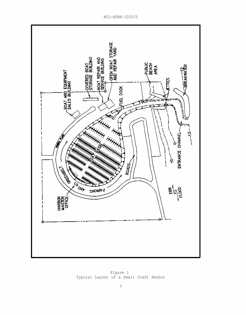
interior channel, fairways, and slip areas, but not the entrance channel.This general rule shall apply only for an average boat length of 30 to35 ft (9.1 - 10.6 m) and where good basin geometry can be obtained. Figure 1represents a typical layout of a small craft harbor and associated berthingfacilities.
2.1.2.2 Land Area. The size of land areas is generally about 80 percent ofthe water area or about 160 m2 per boat.
2.1.2.3 Finger Width. Because wider fingers are needed for two-boat ships,they will occupy about the same area as that required for single-boat slips.
2.1.2.4 Water Area. When bow-and-stern moorings are used in lieu of slips,about 2 to 4 times as much water area (depending on the water depth) isrequired, exclusive of fairways and channels. Single-point moorings requireabout 6 times the area occupied by the same number of bow-and-stern mooringsif full-circle clearance is provided.
2.1.2.5 Launching Ramp or Hoist. An average launching ramp or hoist willlaunch and retrieve about 50 trailered boats on a peak traffic day.
2.1.2.6 Parking Lot. For the normal distribution of small boats, a minimumof three vehicle spaces in the parking lot will be required for every fourboats in the berthing area.
2.1.2.7 Harbor Service Facilities. Minimum land area required for harborservice facilities, ancillary facilities, and roads and hardstands is an areaapproximately equal to the parking area required for berths and operationallaunchings.
2.1.3 Berthing Basin Depths
2.1.3.1 Criteria. The interior basin depth requirements for small craftberthing shall be determined from DM-26.1, Harbors, and also by reckoning theeffect of bottom depth on structures of the berthing system, such as fixed-pier supports, floating pier guide piles and dolphins, and interior wave andsurge baffles.
2.1.3.2 Minimum Depths. Assuming that the maximum depression of a boatbelow the still-water surf will be about 2 ft (.61 m) (due to wave actionand scend), the depth shall be at least 2 feet below the keel of the deepest-draft boat at extreme low water.
3
MIL-HDBK-1025/5
Figure 1Typical Layout of a Small Craft Harbor
4

MIL-HDBK-1025/5
Minimum basin depths shall be as follows:
a) Main basin channel: 15 feet
b) Access slips: 12 feet
c) Berths for boats 30 feet and smaller: 8 feet
d) Berths for boats 65 feet long: 12 feet
e) Berths for boats of intermediate lengths: 8 to 12 feet
2.1.4 Entrance Channel and Structures
2.1.4.1 Channel Alignment. The channel alignment shall be as close to thenatural channel alignment as possible.
2.1.4.2 Channel Width. The waterside approach to the small craft harborshall be as wide as possible to permit safe, simultaneous entrance and exit ofthe widest boat anticipated. For small-boat traffic, allow a minimum width of150 ft (45.1 m) if the entrance is in line with the main channel. Allow aminimum width of 250 ft (76.2m) if the boat is making an immediate turn insidethe boat basin.
2.1.4.3 Channel Depth. Entrance channel depth shall be the sum of draft,vessel squat, one-half of the wave height, and overdepth. An overdepth of1 ft to 2 ft (.30 - .61 m) in soft material and 2 to 3 ft (.61 - .91 m) inrock is allowed for dredging irregularities. Minimum depths shall rangebetween 6 ft (1.83 m) for boats smaller than 20 ft (6.1 m) long and 15 ft(4.6 m) for boats longer than 60 ft (18.3 m).
2.1.4.4 Jetties. Jetties shall be provided to protect the entrance channelfrom waves in the basin and from littoral drift entering the channel from theflanking beaches. Spacing of jetties shall accommodate both the entrancechannel and a protective berm of appropriate width on either side of thejetty. Jetties shall be constructed from the shore-end outward.
2.1.4.5 Other Protection. Where basin configuration warrants, providebreakwaters, groins, and other basin protection such as basin flushing andaccess. Refer to para. 2.5 for design guidelines.
2.1.4.6 Aids to Navigation. Refer to DM-26.1 for navigational aids.
2.1.5 Turning Area. For average berthing basin conditions, provide awidth of water area for turning, and for entering and leaving slips equal to2-l/4 times the length of the longest boat. If there is a predominance ofsingle- or twin-screw boats, this criterion shall be 2-l/2 and 2 respectively.
2.2 Environmental Siting Considerations
2.2.1 Local Weather
5

MIL-HDBK-1025/5
2.2.1.1 Precipitation
a) Adequate surface drainage shall be provided which is capableof draining the waters resulting from a maximum probable rainfall withouteroding the perimeter land, and diverting any possible inflows from thesurrounding land or safely through the small craft harbor complex.
b) Where necessary, covered slips shall be provided to keep thecraft dry above the waterline, and to shed snow, prevent hailstone damage, andshield the craft from excessive exposure to sunlight.
c) In regions where snowfall is heavy, landside structures andslips shall be designed to carry a heavy snow load or to shed snow.
2.2.1.2 Wind
a) Determine the most severe wind condition that might occur atthe site from historical meteorological records. Wind direction and itseffect on low speed maneuvering should also be evaluated.
b) Design floating slips to withstand the horizontal thrust ofthe berthed craft during the design wind condition.
c) Suitable anchorage for the slips shall be provided to preventdrifting of the berthed craft and the entire complex under wind stress.
2.2.1.3 Ice
a) As a precaution against sheet ice damage to boats, specifyboat removal from the water in winter to dry storage or, after hoisting out oftheir slips, leave them suspended above the water surface.
b) Ice damage to fixed and floating slips occurs in three ways:
1) As sheet ice forms, it expands and tends to crush floatsand cut into piles.
2) If the water level rises after freezing has begun, the icesheet hugging the piles exerts an upward force tending to jack them up andthereby reduce penetration into the soil. Repeated freezing and thawing mayeventually lift the piles completely out of the soil.
3) Most ice damage is usually caused by the impact ofdrifting floes on structures as the ice melts in spring.
c) In areas where freezing does not produce a thick ice sheet,ice formation can be prevented near piles, floating slips, and boats by forcedconvection currents.
d) Drive steel or metal-clad timber piles deep enough in certainfoundation soils to develop higher withdrawal resistance so that the ice willslide along the pile as it rises.
6

MIL-HDBK-1025/5
e) Floating slips with tapering or round bottoms shall beprovided so that the pinching effect of the ice squeezes them upward.
f) To prevent erosion of basin perimeters and revetted slopes byexpanding ice sheets, the perimeter slopes shall be provided with smoothconcrete lining. Vertical perimeter walls may be pushed back into soil behindthem in winter and sprung back when the ice thaws.
g) Deflecting booms made of logs or heavy timbers shall be usedto protect the berthing area from drifting ice.
2.2.1.4 Fog. For areas where fog is a significant problem, small craftharbor entrance channels and main fairways should be designed as straight asfeasible, so as to be safely navigable in dense fog by following marker buoysand other channel-marking devices with as few turns as possible.
2.2.2 Wave-Related Factors
2.2.2.1 Swell
a) To reduce wave action from the entrance channel and interiorbasins to acceptable heights, the entrance channel orientation protectivebreakwaters and jetties, and interior wave-dissipating devices, shall beproperly planned and selected.
b) Historical wave data and statistical hindcast data shall beused for orienting the entrance and designing protective structures.
c) Wave-dissipation structures shall be provided to reduce wavesto acceptable heights. Criteria for acceptable maximum wave heights are about2 to 4 feet in the entrance channel, and 1 to 1 l/2 feet in the berthing areasdepending on the characteristic of the using craft.
d) Where a small craft harbor opens into the ocean or a largelake, the entrance shall be oriented for a boat to enter without turningbroadside to the incoming waves.
2.2.2.2 Surge
a) Surge oscillations in the basin cause stress in mooring linesand anchorage systems, and can make boat maneuvering into slip difficult.
b) Vertical basin walls are usually more desirable than poorlyreflective basin perimeters, and rectangular basins are more efficient thanirregular shaped basins for berthing arrangements.
c) Most recreational boats in a small craft harbor areinsensitive to long-period surging. Larger craft may experience fender andmooring line difficulties under long-period surging.
2.2.2.3 Tides
a) Ocean tides may extend considerable length upstream from themouth of large rivers and are semi-predictable for most harbor sites. For any
7

MIL-HDBK-1025/5
coastal site, it is possible to interpolate predictions for the site fromvalues given in the National Oceanic and Atmospheric Administration TidePrediction Tables for the two nearest stations.
b) Extremes of the predicted spring tides provide criteria forsmall craft harbor design accommodating any water level fluctuations that mayoccur.
2.2.3 Water Area Shoaling Factors
2.2.3.1 Littoral Drift
a) The principal cause of shoaling at entrances to harbors islittoral drift.
b) The longshore movement of sand is due mainly to wave action.Structures that change the normal regimen of waves breaking along a coast mayinfluence the littoral movement.
c) If the approach of the prevailing waves is normal to theshore, the initial effect is movement of the littoral material from the lipsinward along each flank of the channel, thereby eroding the lips and shoalingthe inner channel. As the process continues, the channel banks accrete towardthe center of the channel, fed by material from the beach on either side ofthe entrance.
d) Where prevailing wave approach is oblique to the shoreline,sediments being transported along the shore by littoral currents will beinterrupted at the channel opening near the up drift lip and that lip willsoon begin to accrete. As the wave-induced longshore current again begins toimpinge on the shore down drift of the channel mouth, it attempts to reacquireits sediment load. As a result, the down drift lip of the channel will erodeat about the same rate as the up drift lip accretes, and the channel mouthwill migrate in the down drift direction.
e) To minimize entrance shoaling, install jetties along eachflank of the entrance channel from the lips of the mouth seaward beyond thebreaker zone. Structural features of jetty construction shall prevent thematerials from washing through or over the structure into the channel.
2.2.3.2 River Discharge
a) Harbors in off-river basins may undergo shoaling due tosediment deposition in the quiet-water area and eddy currents that may becreated by the entrance configuration and the flowing water in the river.
b) To minimize shoaling, provide a flat area on the downstreamlip of the entrance from which a dragline can excavate deposits from thebottom of the entrance channel, and cast the deposits into the riverdownstream from the entrance. A permit from the State Marine ResourcesCommission and the Corps of Engineers is required for water disposal of theexcavated deposits. The entrance shall be maintained narrow to permit such anoperation. A training dike installed off the upstream will reduce sedimentdeposition. (See Figure 2.)
8

MIL-HDBK-1025/5
(1) Permit required from Corps of Engineers for water disposal ofexcavated material.
Figure 2Maintenance of Entrance to Off-River Basin
With Land-Based Equipment (Schematic)
9
MIL-HDBK-1025/5
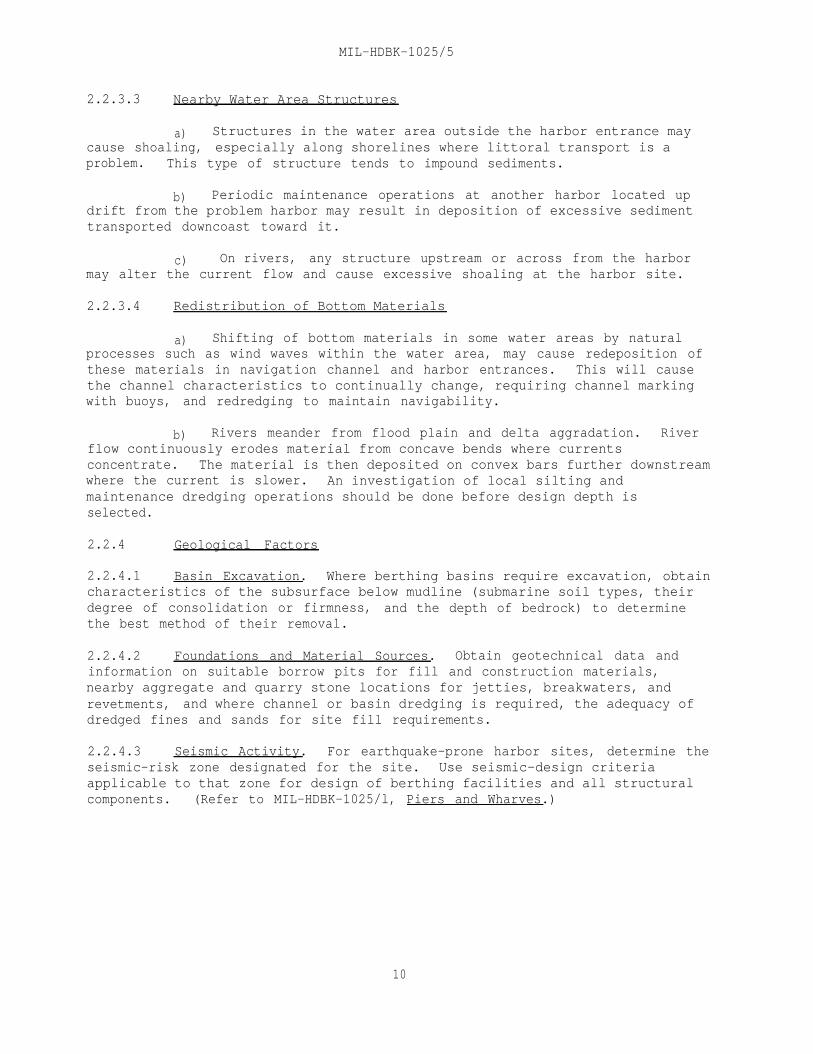
2.2.3.3 Nearby Water Area Structures
a) Structures in the water area outside the harbor entrance maycause shoaling, especially along shorelines where littoral transport is aproblem. This type of structure tends to impound sediments.
b) Periodic maintenance operations at another harbor located updrift from the problem harbor may result in deposition of excessive sedimenttransported downcoast toward it.
c) On rivers, any structure upstream or across from the harbormay alter the current flow and cause excessive shoaling at the harbor site.
2.2.3.4 Redistribution of Bottom Materials
a) Shifting of bottom materials in some water areas by naturalprocesses such as wind waves within the water area, may cause redeposition ofthese materials in navigation channel and harbor entrances. This will causethe channel characteristics to continually change, requiring channel markingwith buoys, and redredging to maintain navigability.
b) Rivers meander from flood plain and delta aggradation. Riverflow continuously erodes material from concave bends where currentsconcentrate. The material is then deposited on convex bars further downstreamwhere the current is slower. An investigation of local silting andmaintenance dredging operations should be done before design depth isselected.
2.2.4 Geological Factors
2.2.4.1 Basin Excavation. Where berthing basins require excavation, obtaincharacteristics of the subsurface below mudline (submarine soil types, theirdegree of consolidation or firmness, and the depth of bedrock) to determinethe best method of their removal.
2.2.4.2 Foundations and Material Sources. Obtain geotechnical data andinformation on suitable borrow pits for fill and construction materials,nearby aggregate and quarry stone locations for jetties, breakwaters, andrevetments, and where channel or basin dredging is required, the adequacy ofdredged fines and sands for site fill requirements.
2.2.4.3 Seismic Activity. For earthquake-prone harbor sites, determine theseismic-risk zone designated for the site. Use seismic-design criteriaapplicable to that zone for design of berthing facilities and all structuralcomponents. (Refer to MIL-HDBK-1025/l, Piers and Wharves.)
10

MIL-HDBK-1025/5
2.2.5 Impact on Environment. Consider the following environmental issuesand concerns:
a) Disposal of dredge material.
b) Water quality.
c) Preservation of the ecology.
d) Esthetics.
2.3 Design Criteria for the Berthing System
2.3.1 Slip and Berth Clearances
2.3.1.1 Berth Clearance. Boats of 40 ft (12.2 m) orcenter spacing of finger piers.
less for center-to-
a) In the case of single berths, use the maximum boat width plus1 l/2 ft (.46 m) on each side plus the width of finger piers.
b) In the case of double berths, use twice the average boat widthplus one foot at each finger plus 3 ft (.91 m) between boats plus the width offinger piers.
2.3.1.2 Finger Piers
a) Fingers may be built inclined or perpendicular to headers.The latter orientation is preferred because of the simplicity of constructionand greater strength of junctions between fingers and headers.
b) Inclined fingers are generally used only where spacerestrictions limit the turning area opposite the slips or for alignment in thedirection of prevailing winds or water flow.
2.3.1.3 Fairway Widths. Provide the following fairway widths betweenfinger ends:
a) For power craft, minimum 2 times the length of the longestcraft served.
b) For sailboats, minimum 2 l/2 times the slip length.
c) For 45 degree berthing, minimum 1 l/2 times the length of thelongest boat served.
2.3.1.4 Mooring Layouts.
a) See Figure 3 and refer to DM-26.1 for mooring and berthinglayouts and the type of mooring used in each case.
b) Layout A is not convenient for embarking alongside piers.Layout B is not suitable where a large tidal range prevails. Layout Drequires wider spacing between finger piers than Layout C. Layout E provides
11

MIL-HDBK-1025/5
flexibility in accommodating boats of different lengths. Layout F economizesspace and piers. Layout G permits no dry access to land and poses difficultyin leaving mooring if outer boats are not manned.
c) Layouts G and H are not recommended unless special situationsand basin conditions warrant.
d) Access to a star-shaped-cluster moorage is either by shore-boat or by a star-to-shore extension of one of the fingers.
2.3.1.5 Slip and Berthing Arrangements. Features include the following:
a) In a boat slip, the craft may be tied away from the dockstructure, usually with fore-and-aft ties on both ends. In a single-boatslip, the craft shall be flanked on each side by a finger pier. In a double-boat slip, a tie pile centered between the finger ends, three-point ties,steel whips or any cooperative switch-tie system is expedient.
b) Small boats in relatively quiet waters shall be berthed to adock with stern hooks or bow clamps.
c) The most common slip arrangement comprises a series of piersor head walks extending perpendicular to the bulkhead to a pierhead line, withfinger piers extending at right angles from the head walk on either side.
d) The average head walk width is about 8 ft (2.4 m) with a rangeof about 5 to 16 ft (1.5 - 4.9 m). For wider head walks, provide some widthfor bearing-pile risers, locker boxes, firefighting equipment, and utilitylines. For narrower head walks, it is preferable to locate all obstructionsto knees at the junctions of finger piers. Extra wide head walks shallgenerally be used in fixed-pier installations.
e) Boarding fingers for single-boat slips shall be about 3 ft(.91 m) wide. Floating fingers longer than 35 ft (10.7 m) are usually 4 ft(1.2 m) wide. In double-boat slip construction, use a finger width of 4 ftfor all slip lengths.
2.3.1.6 Dimensional Criteria and Typical Details
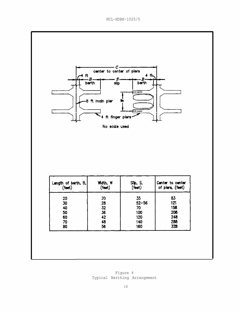
a) See Figure 4 for a typical double berthing arrangement thathas been used successfully.
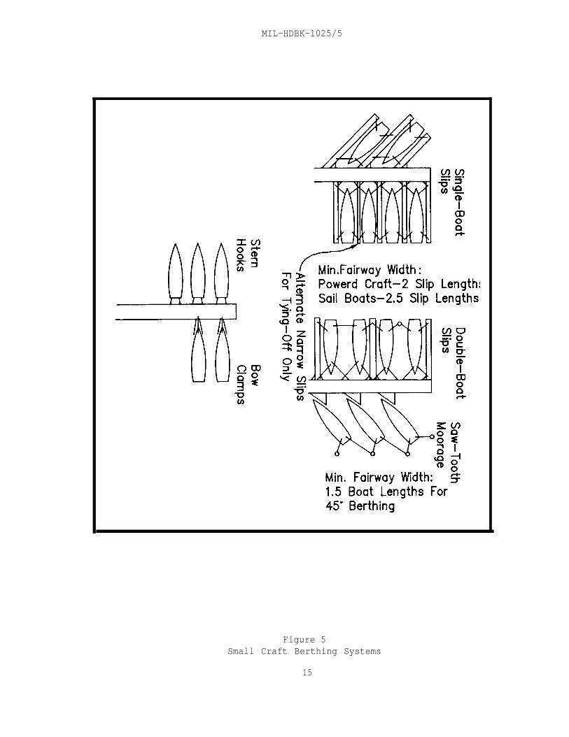
b) Figure 5 illustrates single- and double-boat slips, angularmoorage, applicable fairway widths, and the use of stern hooks and bowclamps.
c) Figure 6 is a graphical representation of average beam widthand maximum depth of keels for various craft lengths, and suggested widths forright-angle slips where the actual dimensions of berthing craft are not known.
d) For typical details, refer to MIL-HDBK-1025/l.
12

MIL-HDBK-1025/5
Type of mooring
A Stern to quay,o r p o n t o o n ,
jetty
to piles
E Alongside quaysjetties or pontoonssingle banked
F Alongside quays
B Ditto but bowsjetties or pontoons
moored to anchorsup to 3 or 4 abreast
or buoys
G Between piles
C Alongside fingerpiers or catwalksone yacht on eachside of each finger H Star finger berths
D Ditto but more thanone yacht on eachside of each finger
Figure 3Typical Small Craft Mooring Layouts
13
MIL-HDBK-1025/5
Figure 4Typical Berthing Arrangement
14
MIL-HDBK-1025/5
Figure 5Small Craft Berthing Systems
15

MIL-HDBK-1025/5
Figure 6Dimensional Criteria for Berthed Craft
16
MIL-HDBK-1025/5
2.3.2 Fixed Versus Floating Pier System
2.3.2.1 System Selection
a) The decision to select fixed or floating piers for any smallcraft harbor basin shall be based on economy, tidal range, safety andconvenience.
b) A combination of fixed and floating piers shall generally beconsidered satisfactory for some sites.
c) Advantages of a fixed-pier system are:
1) Usually less expensive to construct.
2) Less expensive to maintain.
3) Stronger, more durable and stable.
4) Will bear heavier loadings.
5) Withstand impact more readily than floating-pier system.
d) Advantages of a floating-pier system are:
1) Constancy of level between pier and water
2) Rearrangement of layout is possible.
3) Adjustment of mooring lines is unnecessary
4) Less likelihood of damage to boats under tidal conditions.
2.3.2.2 Selection Criteria. These include the following:
a) In harbor basins, where water surface levels do not fluctuatemore than 2 ft (.61 m) and the water depth is about 20 ft (6.1 m) or less, theberthing docks and slips should usually be of fixed construction.
b) Fixed berths should be considered for tidal ranges of up to5 ft (1.5 m).
c) Where water surface levels fluctuate more than 5 ft, afloating-pier system is mandatory.
2.3.3 Fixed-Pier Berthing Systems
2.3.3.1 General Features. These include the following:
a) Piers shall be no wider than safe pedestrian and handcarttraffic requires.
b) Fingers shall be no wider than 3 ft (.91 m).
17
MIL-HDBK-1025/5
c) Main walkways shall be 4 to 8 ft (1.2 - 2.4 m) wide.
d) Pile trestles are generally used to support stringers anddecking with cross and sway bracing installed.
e) Deck elevations shall be approximately 1 ft (.30 m) aboveextremely high water.
f) Construction of fixed-level berthing systems may be eithertimber, reinforced concrete, steel or aluminum. A timber superstructure ispreferred because of the ease with which attachments may be made after finalconstruction.
g) Berthing structures and components using factory-built unitsfor easy field installation are mostly of tubular and pressed-steelconstruction with either stamped metal or timber plank decks.
h) Covered berthing is especially adaptable to a fixed-piersystem.
i) Utility lines shall be carried under the deck or along thestringers for supporting the roof.
j) See para. 2.3.4. for deck materials and surface.
2.3.3.2 Vertical Loading. Design fixed structures for deck live loading ofnot less than 50 pounds per square foot (psf) for fingers and 100 psf for mainwalks and building floors. When vehicles are to be allowed on main walks, thedesign loading shall be increased accordingly (refer to MIL-HDBK-1025/l).
2.3.3.3 Other Design Criteria. Other design criteria shall be as providedin MIL-HDBK-1025/l.
2.3.3.4 Typical Construction. Figure 7 represents a typical fixed-piersystem.
2.3.4 Floating-Pier Berthing Systems
2.3.4.1 General Considerations. General considerations include:
a) Many floating-pier systems are commercially available.Consider an appropriate and commonly used and tested system to suit specificbasin peculiarities.
b) In a floating-pier system, the basic framework that transmitsunequal stresses imposed by current, wave action, and wind from one float toanother throughout the system is generally constructed of timber. Most othermaterials cannot take the almost constant flexure to which the framing issubject over prolonged periods without fatigue failure. Some metal stringersystems have been designed with flexible connections which keep flexure belowthe fatigue failure limit.
18

MIL-HDBK-1025/5
Figure 7Typical Fixed Finger Pier System
19

MIL-HDBK-1025/5
2.3.4.2 Flotation Materials
a) Timber Log. Although least expensive in some areas, it has atendency to become waterlogged and sink in a few years. Use is generally notrecommended.
b) Extruded Polystyrene (Styrofoam). Available in several sizesof precast or premolded forms, mounted under a timber frame with timber deck.
c) Expanded-Pellet Polystyrene. Material shall be firm incomposition and essentially unicellular. Polystyrene planks should conform tothe following requirements:
1) Be hydrocarbon resistant, and evidence no apparentsoftening or swelling when tested by the immersion method stipulated inMilitary Specification MIL-P-40619, Plastic Material, Cellular, Polystyrene(For Buoyancy Applications).
2) Minimum Properties. Density = l-1/2 pounds/cu. ft.Compressive strength = 20 pounds/cu. in. at 5 percent deflection. Shearstrength - 25 pounds psi and 40 psi tensile strength.
3) Have maximum water absorption of 0.12 psf of skinless orrindless surface, when tested by the immersion method stipulated in MilitarySpecification MIL-P-40619.
d) Polyurethane Foam. This is more expensive than pelletpolystyrene; however, it is sometimes preferred because of its hydrocarbonresistance. Polyurethane foam requires a covering with an oxidation-resistantmaterial; the nonabsorbent, noncellular variety should be specified.
e) Waterproof Shells. Shell-type floats can be ballasted withwater or sand to allow corrective leveling of the deck after installation.However, they are susceptible to leakage and loss of buoyancy if the shellbecomes permeable for any reason. Some of the shell-type floats in use are:
1) Fiberglass of plastic-coated shell with a molded foam coreover which a reinforced concrete deck is poured. The edge beam, cross beam,and the tie-rod system in this construction make the units exceptionally toughand strong. Synthetic shell floats are not affected by hydrocarbons, brackishwater, or any other common contaminant likely to be found in a small craftharbor.
2) Prefabricated metal floats of steel and aluminum. Theshells are folded and welded into rectangular units comprising thin-gaugesheets with stiffening baffles for greater strengths. Preservative coatingsare applied to both sides of all corrodible metals. Their use in freshwaterharbor basins is feasible, but in saltwater environment the use of metalfloats still remains questionable.
3) Jettisoned fuel tanks from military aircraft. This typeis expedient when sufficient surplus can be procured at low cost.
20

MIL-HDBK-1025/5
4) Pipes. Tubular steel floats with attached clip angles ateach end bolted to a steel deck framework are used. Coating the entireframework, including the tubes, with coal-tar epoxy provides protectionagainst corrosion.
5) Steel drums. They are expedient and inexpensive in shortlife of substandard construction. Maintenance costs in seawater would beprohibitive.
f) Concrete Floats. These provide maintenance-free permanence toconcrete construction and added stability to the floating pier. Lightweightaggregates to keep the dead load to a minimum, prevention of shrinkage cracks,honeycombing and segregation, and precise mix control are essential. Concretefloats can be made with or without reinforcement. When concrete floats arereinforced, a galvanized wire mesh shall normally be used. The float shouldbe designed so that at no point will the allowable tensile strength of theconcrete be exceeded.
g) Wooden Floats.
1) Pressure-treated wood is in use for floating dock modules.All wood shall be treated in accordance with AWPB Standard MPL for SoftwoodLumber, Timber and Plywood Pressure Treated for Marine (Saltwater) Exposure,as recommended for a specific site.
2) Flotation units shall include a polyethylene pan,polystyrene foam block, and polyethylene cap sheet.
h) Figures 8, 9, and 10 show various types of floats commonlyused.
2.3.4.3 Deck Materials and Surface
a) Wood Plank Deck. It is used without a coating and also with acoating to minimize splintering. Roughened surface texture of coatingsimparts nonskid quality. Planks should not exceed 10 in. (254 mm) in widthand shall be spaced l/4 in. (6.35 m) apart. Diagonal planking is sometimesused for floating docks to provide cross-bracing strength. For appearance andwearing quality, the planking should be given two priming coats.
b) Plywood Decking. Commercial grades of exterior plywood aremade with waterproof glues of excellent quality and may be safely used forexposed decking. Plywood of 3/4 in. (19.05 mm) thickness is more expensivethan 2 in. (50.8 mm) wood planking, but provides greater structural strengthin cross bracing. Plywood decking should be crowned slightly to avoid pondingin wet weather. It should be painted as described for wood planks. Asynthetic surfacing may be pressure bonded to plywood deck panels under heatto provide nonskid and long-wearing quality.
c) Laminated Plank Deck. Laminated plank deck uses nominal2 by 3 in. or 2 by 4 in. cedar pieces glued together side by side for use incontinuous decking in large, thick planks of any length or width, and itprovides high stiffness. Laminated decks may be used without any additionalframing.
21

MIL-HDBK-1025/5
Figure 8Various Types of Floats
22

MIL-HDBK-1025/5
LONGITUDINAL SECTION TRANSVERSE SECTION
Concrete Placed Directly On Foam AfterReinforcing And Stringers Are In Place
Expanded Polystyrene Foam WithMolded Deprssions For R.C. CrossBeams
Figure 9Typical Foam Float With Concrete Deck
23

MIL-HDBK-1025/5
Figure 10Typical Water-Ballasted Floating Dock
24

MIL-HDBK-1025/5
d) Sandwich Deck. It has a polystyrene core glued to a plywoodtop and bottom faces and edged with 2-in. (50.8 mm) lumber. It also has highstiffness and is lightweight. Cost of the sandwich deck compares favorablywith the laminated plank deck.
e) Concrete Slab Deck. Separate reinforced concrete deck slabsare sealed to the lips of open-top unreinforced floats with epoxy cement.Another type of concrete deck is a monolithic part of a float. Concrete decksprovide a durable, high-stiffness, nonskid, maintenance-free deck surface.The cost is high in comparison to timber decking and repairs may bedifficult.
f) Metal Deck. Sheet metal modular units, with surface anodizingor baked enamel coatings are used in freshwater environment. Repairs aredifficult if bent or pulled apart at their connections.
g) Fiberglass and Synthetic Deck. Panels of fiberglass and othersynthetics are used with floating-pier systems. They have little resistanceagainst torsional bending, and must rely on the framework for stiffness andprevention of damage by racking action in rough waters. Some types of panelshave excellent wearing qualities, but tend to be rather brittle.
h) Wearing Surface:
1) The top surface of decking should withstand prolongedexposure to sunlight, frequent wetting and drying, severe abrasion by scuffingand dropped objects, and a certain amount of flexure.
2) It should not crack or peel off.
3) It should be nonskid, not prone to staining, and easilycleaned of oil, paint spills and dirt.
2.3.4.4 Deck Framing and Float Connections
a) Vertical Stresses Induced by Wave Action. Depending on theweight of the floating system as a whole, and assuming a design wave ofapproximately 2 ft (.61 m) high, the section modulus about a horizontal axisfor timber framing: (based on empirical data) should range from a nominal20 in.3 to 30 in.3 per foot of finger deck-width. Thus an adequate stringersystem for a 4 ft (1.2 m) wide finger floating on foam or lightweight shellswould be a 2 in. by 6 in. (50.8 mm - 152.4 mm) plank inside and a 2 in. by10 in. plank outside on each side of the finger. However, since all boltheads, nuts, and ends of tie rods must be recessed sufficiently into the outerstringer to avoid damage to boat hulls, a 3 in. or 4 in. (76.2 - 101.6 mm)nominal thickness is recommended for all outside stringers. The stringersshould be in 16 ft to 20 ft (4.9 - 6.1 m) lengths with butt joint swell offsetand with adequate bolting to develop bending strength. For concrete floats,the same deck would require stronger framing. In a lightweight system, atorsion bar of 3 in. or 3-1/2 in. (76.2 mm - 88.9 mm) galvanized pipe withwelded-on end plates, centered under the deck of each finger is recommended.A glulam beam has been developed which strengthens the side stringer system.A glulam deck 3-1/4 in. (82.5 mm) thick provides excellent torsionalresistance.
25

MIL-HDBK-1025/5
b) Horizontal Stresses. For a design wind load of 15 psf (seepara. 2.3.5), stringers based on the foregoing vertical-stress criteria willnormally be adequate for horizontal stresses in 3 ft (.91 m) wide fingers upto 30 ft (9.1 m) long and 4-ft wide fingers up to 40 ft (12.2 m) longcantilevered from the rigid main walk or header, provided that generous kneesare installed and attachments to the walk or header are adequate to resist thedesign moment. For fingers longer than approximately 40 feet, adequatecantilever strength is difficult to develop, and end guide piles may berequired. The fingers should be designed for the same wind loading criteria,considering the end to be pinned and the header connection to be rigid at theouter end of the knee. Cross bracing shall be provided. The bracing can bein the form of diagonal or knee bracing, in some or all of a finger below aplank deck, or it can be solid deck plates of plywood, concrete, or glulamdecking.
c) Securing Flotation Elements. Some float and deck sections arebuilt as integral units. When the floats are separate, they shall be attachedor cradled under the deck frame. Connections used are as follows:
1) Foam logs or planks are dowelled, bolted, or strapped tothe framing. Water-resistant epoxy glues are being developed that givepromise of producing a strong reliable bond to the deck frame.
2) Large independent pontoons of concrete, fiberglass shells,or composite construction normally need only to be cradled; i.e., preventedfrom sliding laterally by outer stringers and cross struts. This facilitatestheir removal for replacement or maintenance when required. However, in areasexposed to larger waves, they shall be strapped to their saddles.
3) Strapping. If metal straps are used they should bestainless steel. Nylon straps are suitable, but must be adequately tightenedinitially.
4) Bolting. Bolts shall be of corrosion-resistant material.
5) Strength of Foam. Bearing boards should have sufficientbearing surface to prevent crushing of the foam. The foam has a safecompressive strength (with negligible deflection) of approximately 5 psi.Being weak in bending, bearing contact areas shall be spaced not more than2 ft (6.1 m) apart along the deck and shall be continuous along each edge.
d) Figure 11 represents typical deck framing and floatconnections in use.
2.3.4.5 Vertical Loading and Deck Levels
a) Floating piers and docks for small craft should normally ridewith the deck uniformly at 15 to 20 in. (381 - 508 mm) above the water surfaceunder dead loading to provide ease of boarding and to assure that the sidestringers are below the gunwales of the smaller craft and below the sprayrails of larger craft. The lower limit is necessary to prevent waveovertopping of the deck at full design live loading.
26

MIL-HDBK-1025/5
Figure 11Typical Deck Framing Systems and Float Connections
27

MIL-HDBK-1025/5
b) Design live loading shall be 25 psf. However, on fuel docksor loading docks, a higher live loading, depending on the anticipated usage,is required. Under full live load plus dead load, the flotation elementsshould not be submerged more than 75 percent of their volume.
c) When concentrated live loads on headers exceed the design liveload, design shall be such as to distribute such loads over a number ofnearby, attached fingers and a considerable length of the header itself.
d) The deck system and all interfloat stringers shall be designedfor 50 psf.
e) Deck loading shall be such that a concentrated load of 500pounds can be placed anywhere on the deck surface without overstressing theframing members and without tilting the deck more than six degrees from thehorizontal.
f) For boats with a low rub strake, the stringer shall be wideenough to extend down to within 8 in. (244 mm) of the water surface under deadload only.
g) For boats with high gunwales, provide low level floatingfingers with vertical fender posts that extend upward from each side a fewfeet above deck level at intervals of about 8 ft (2.4 m).
2.3.4.6 Typical Construction. Figure 12 represents a typical floating-piersystem.
2.3.5 Lateral Loading
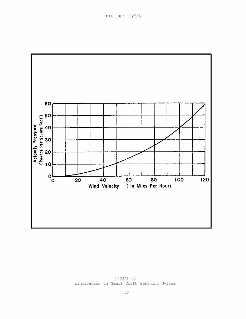
2.3.5.1 Loading. Maximum lateral loading of a fixed- or floating-piersystem is usually produced by strong winds blowing against the structure andberthed craft. Such loading usually exceeds normal docking impact loads orcurrent drag. The design lateral load is based on a given wind velocityacting on the above water profile of the system and craft. This loading(velocity pressure in pounds per square foot) for wind velocities up to 104knots is shown in Figure 13. The wind velocities are for steady-stateconditions, neglecting gusts. For wind velocities at various geographicallocations, see NAVFAC DM-26.6, Mooring Design Physical and Empirical Data.
2.3.5.2 Analysis
walk.a) Check both parallel and perpendicular directions to the main
b) Determine average profile height for berthing craft. (SeeFigure 14.) It is often taken as 15 percent of the slip length in openberths.
c) In computing the parallel windload on a line of boats, assumethat all shielded craft experience only 20 percent of the windloading that isapplied to the first (unshielded) boat.
28

MIL-HDBK-1025/5
Figure 12Typical Floating Pier System
29
MIL-HDBK-1025/5
Wind Velocity ( in Miles Per Hour)
Figure 13Windloading on Small Craft Berthing System
30

MIL-HDBK-1025/5
Figure 14Variation of Average Profile Height of
Berthed Craft with Craft Length
31

MIL-HDBK-1025/5
d) In computing the perpendicular windloading on a system, obtainthe total area on which the wind acts by multiplying the average craft profileheight by the slip width and that product by the total number of slips, thenadding to the result the above water areas of the finger pier ends exposed tothe wind.
e) Where slips are provided on both sides of the main walk, thearea calculation shall include the side that berths the set of boats with thelargest average profile height.
f) Multiply the area by 115 percent to account for the wind forceon the sheltered or leeward boat row.
g) Figure 15 represents a sample computation for lateral loadingon a typical open-pier system.
2.3.6 Anchorage Systems
2.3.6.1 Selection Criteria. Floating piers and docks should be anchoredagainst lateral movement likely to be caused by wind, water currents, andvessel, ice or floating-debris impact. For selection of an anchorage system,consider depth of water in the small craft basin, extent of water-levelfluctuations, the prevailing current, and the submarine bed material.
2.3.6.2 Systems
a) Anchor Piles. These are simple and are the most commonlyused. They require firm but penetrable subsurface strata, a bottom depth notexceeding 30 ft (9.1 m) at highest water level, and relatively moderatehorizontal loading conditions. Where pile anchorage is used, guides shall beincorporated in the deck structure. Commonly used guides are metal hoops,rectangular wood collars, and rollers. In well-protected basins, use rollersonly for those piles that are found to be in almost continuous contact withthe guides. Use collars with hardwood blocks at other piles. Metal hoopsshall not be used with bare wood piles since they tend to crush the woodfibers.
b) Anchor Lines. Where a boat basin is constructed in deepwater or where large water-level fluctuations occur, floating structures areusually anchored in place with steel cables or chains. Where the entirefloating system requires movement through considerable distances in and outwith water-level changes, special anchor barges with hand winches are used. Aline-anchorage system usually uses two outer anchor lines extending about 45degrees from the outer corners of the floating system, and two lines tying thesystem back to shore.
c) River Anchorage. River currents usually stress an anchoragesystem more severely than still-water or tidal basins. Long, trailing fingerpiers can be tied to piles or to dolphins. Figure 16 represents a typicalriver anchorage system.
32

MIL-HDBK-1025/5
NOT TO SCALE
° Design Wind Load: 15 PSF
° Perpendicular Wind40’ Boats: 8 Each x 19’ Beam x 5.5’ Height x 15 PSF = 12,540 Lbs.Fingers: 9 Each x 4’ Beam x 1.5’ Height x 15 PSF = 810 Lbs.
Multiply by 1.5 for Row of 30’ Boats = 1.15 x 13,350 Lbs.78’ Boat: 20’ Beam x 7.4’ Height x 15 PSF
TOTAL PERPENDICULAR LOAD:
= 15,352.5 Lbs.= 2,220.O Lbs.
= 17,572.5 Lbs.
° Parallel Wind78’ Boats: 78’ Each x 7.5’ Beam x 15 PSF = 8,658 Lbs.40’ Boats: 8 Each x 40’ x 5.5’ Height x 3 PSF = 5,280 Lbs.30’ Boats: 10 Each x 30’ x 4.8’ Height x 3 PSF = 4,320 Lbs.
TOTAL PARALLEL LOAD: 18,258 Lbs.
° Reckon Parallel windloading for Design
Figure 15Sample Calculation for Windloading on a Floating Pier System
33

MIL-HDBK-1025/5
d) Anchorage of Covered Floating System.
1) Dolphins are usually used instead of anchor piles.
2) If the water depth is significant, submerged structuralties across finger ends well below the keel depth of the berthed craft aresometimes used to strengthen a covered floating system. (See Figure 17.)
2.3.7 Approach Piers and Gangways
2.3.7.1 General Criteria. These include the following:
a) Access to the berthing docks and slips from the basin shall beaccomplished by a brow "fixed-pier approach" to a fixed berthing system and bya hinged gangway to a floating-pier system.
b) Fixed-pier approach is an extension of the head walk to alanding on the bulkhead wall or an abutment at the shoulder of a sloping bank.In floating systems, one end of the gangway shall be supported on floats. Itshould be lightweight and only long enough to result in some predeterminedmaximum slope (1 on 3) at extreme low water level. For slopes steeper than1 on 3, a hinged staircase with self-leveling steps shall be provided.
c) Where the boat basin perimeter is appreciably higher thanmaximum high water, the brow shall be ramped down to 1 ft or 2 ft(.31 - .61 m) above the elevation at its outer end to decrease the slope ofthe gangway at low water.
d) The gangway may be narrower than either the approach pier(brow) or the main walk.
e) Length of gangways shall be such that the slope will not begreater than approximately 1 on 2-1/2 at maximum low water.
f) Weight of gangways shall be kept as small as possible.
g) Gangway construction may be of timber, steel, aluminum,fiberglass, or a combination of these materials. A typical gangway is a pairof steel or wood stringers with a plywood deck.
h) Gangways shall have handrails. A 3 ft (.91 m) width betweenhandrails is the minimum, and 4 to 5 ft (1.2 - 1.5 m) is the minimum if thepier has multiple berths or if the gangway traffic is heavy. Typicalconstruction is Warren-truss welded-pipe handrail.
i) Gangways shall be hinged at the top inside edge of a perimeterbulkhead wall. If the perimeter is a sloping bank, provide a short fixed-approach pier to reduce the length and weight of the gangway. The hinge atthe upper end of the gangway shall be of rugged design.
34

MIL-HDBK-1025/5
Figure 16Typical River Anchorage System
35
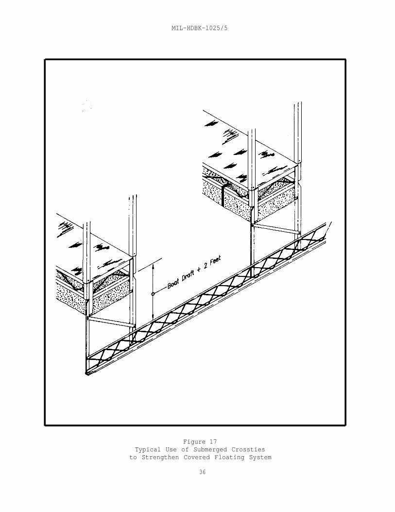
MIL-HDBK-1025/5
Figure 17Typical Use of Submerged Crossties
to Strengthen Covered Floating System
36

MIL-HDBK-1025/5
j) Provide sliding ends for gangways weighing less than500 pounds. For heavier gangways, provide rollers and aprons. The apronplates shall be long enough to clear the ends of the roller guides at lowwater level and attached to the bottom end of the gangway with a pipe-and-rodhinge. (See Figure 18.)
2.4 Design Criteria for Other Sheltered Basin Structures
2.4.1 Perimeter Stabilization
2.4.1.1 Objectives. Perimeter stabilization shall be provided:
a) To retain the perimeter material or to hold it on a givenslope against such internal forces as those causing sloughing or piping ofmaterial under a wall or through a revetment.
b) To prevent damage to the perimeter by external forces whichmight erode or damage the slope or perimeter wall through wave action,currents, and impact by floating objects.
2.4.1.2 Structures. The perimeter inside the sheltered harbor basin shall,depending on the bank conditions and the degree of stabilization required, bedesigned as:
a) Perimeter beach of existing or imported materials.
b) Revetted slope.
c) Gabioned slope.
d) Vertical bulkhead.
e) Some combination of the above.
2.4.2 Perimeter Beach
2.4.2.1 Slopes
a) Where economic considerations warrant the perimeter of thebasin be a sand beach, the slope shall not, ordinarily, be steeper than 1 on 8(1 on 10 for fine sand) within the maximum range of water-level fluctuation inthe basin.
b) Where the shore face consists of gravel, pebbles, or similarrock fragments or sizes rather than sand, littoral transport processes areusually too weak to cause any significant lateral displacement and the slopemay be increased up to about 1 on 5.
c) Underwater stable slopes at depths of 3 ft (.91 m) or morebelow extreme low water vary from about 1 on 4 for cohesionless fine siltysands to about 1 on l-1/4 for some clayey soils in cuts.
37

MIL-HDBK-1025/5
Figure 18Framing and Hinge Detail for Pipe and Rod
Plate Hinge for Heavy Gangway
38

MIL-HDBK-1025/5
d) Bay mud and some lake-bottom materials often "fluff up" upondredging, and will stabilize only on underwater slopes of 1 on 10 or flatter.Waste such material outside the basin and stabilize the slopes with importedsand.
2.4.2.2 Profile. Figure 19(a) represents a typical beach slope profile.
2.4.2.3 Design Details. (See Shore Protection Manual, Volumes I and II.)
2.4.3 Revetted Slope
2.4.3.1 Revetments
a) Where bank conditions require armoring the slopes, provide arevetment of armor stone layer or precast concrete slabs placed on a filtercourse of spalls or gravel or tough, continuous fabric cloth.
b) Revetments are normally stable only to a steepness of about1 on 1-3/4.
c) Materials used are armored stone or precast concrete blocks.
2.4.3.2 Armoring
a) Extreme wave action and currents will determine minimum stonesize of a riprap or revetted slope.
b) Because of the strong pumping action of waves and eddycurrents, armor stones shall have a normal thickness of twice the averagestone dimensions.
2.4.3.3 Filtering Devices. These are poorly graded gravel or stone filterand continuous, tough synthetic cloth filter.
2.4.3.4 Profile. Figures 19(b), 19(c) and 19(d) represent typical revettedslope profiles.
2.4.3.5 Design Details. (Refer to Shore Protection Manual, VolumesI and II.)
2.4.4 Gabioned Slope
2.4.4.1 Use. Where adequate small-sized stone is available, rock-filledwire mesh gabions permit installation of steep slopes for perimeterstabilization at relatively low cost.
2.4.4.2 Construction
a) Heavy-duty wire mesh baskets with rectangular sides and ofconvenient size tailored for construction are commercially available forshipment to site in collapsed form.
b) They are galvanized for freshwater use, and galvanized plusPVC-coated for saltwater use.
39

MIL-HDBK-1025/5
Figure 19
Typical Beach and Revetted Slope Profiles
40
MIL-HDBK-1025/5
c) The filled baskets may be placed vertically on top of eachother.
d) For greater stability, they should be canted back to about a 4to 1 batter. Battering may also be done by setback of successive rows for aterraced appearance.
e) The gabioned slope shall be backed by a layer of filter clothto prevent the pump out of fine material from the earthbank behind it.
f) Use of gabion construction has been limited so far. Itspermanence is not yet well established.
2.4.4.3 Typical Details. (See Figure 20.)
2.4.5 Vertical Bulkhead
2.4.5.1 Use Criteria. For small craft berthing basins, consider thefollowing:
a) Vertical walls reflect waves and should be avoided where surgeand partially attenuated wave penetration into the basin interior cannot besatisfactorily avoided.
b) If the site can be readily unwatered and if substrata are notso fluidic as to require deep cutoff walls, cast-in-place concrete bulkheadconstruction shall be used.
c) In other cases, use sheet piling bulkhead.
d) Because the perimeter wall in a small craft harbor is seldomused as a breasting dock, the bulkhead is usually carried only to the lowwater elevation, and a partially revetted underwater slope shall extend fromthe base of the bulkhead wall down to design depth.
e) The lower edge of the bulkhead wall shall extend not less than2 ft (.61 m) below the design lowest water level. Where wave or other wateraction occurs, extend the walls below the lowest design low water level to aminimum depth of two times the maximum wave height to minimize the possibilityof pump out of fine material from behind the wall.
f) The top of the bulkhead wall shall be 2 or 3 ft (.61 - .91 mabove maximum high water.
2.4.5.2 Types. Types used for small-craft basins include:
a) Tieback pile-type timber bulkhead.
b) Steel or aluminum sheet pile bulkhead.
c) Concrete bulkhead.
d) Concrete structure with revetted slope.
41

MIL-HDBK-1025/5
Figure 20Typical Use of Gabions in Small- Craft Harbor Construction
42

MIL-HDBK-1025/5
2.4.5.3 Design Details. For design details, refer to DM-25.4, Seawalls,Bulkheads, and Quaywalls.
2.4.5.4 General Considerations
a) Timber bulkheads often fail because of corrosion, abrasion,fatigue failure of metal connections, or abrasion of the wood by looseconnections, and not so much as a result of deterioration of wood members.
b) Steel or aluminum sheet pile bulkhead can be installedexpeditiously and at a relatively low cost with lightweight sheet pilesections.
c) Commonly used construction is a concrete wall with a verticalor slightly battered face extending to about extreme low water level, and anarmored slope extending from that level down to the design depth of the basin.
d) To prevent wave or eddy current scour at low water levels,armoring of revetted slope shall extend from the wall to about 5 ft (1.52 m)below extreme low water.
e) Concrete perimeter bulkheads are the most durable.
2.5 Design Criteria for Entrance Channel and Protective Structures
2.5.1 Entrance Channel
2.5.1.1 Location
a) For siting entrance or approach channel, consider:
1) Natural water depths
2) Character of waves approaching the harbor.
b) Analyze the following data:
1) Hydrographic (site bathymetry) survey.
2) Wave generation and refraction.
3) Littoral drift.
2.5.1.2 Design Criteria. These include the following:
a) To the extent the harbor configuration and conditions allow,the channel alignment shall be as close to the natural channel alignment aspossible. Bends, where necessary, shall be gradual.
b) Minimum Width. For small boat traffic, provide minimum 50 ft(15.2 m) or 5 times the beam of the widest boat expected to be berthed in thebasin.
43

MIL-HDBK-1025/5
c) Minimum Depth. Use the sum of the values of design draft,squat, and one-half the wave height plus overdepth requirements to obtaindesign minimum depth.
2.5.1.3 Construction
a) For channel construction in most bottom materials, dredge flatslopes in the channel or provide additional width or depth to contain thematerial sloughing from the dredged slope.
b) Type of dredging shall be decided primarily on the basis ofthe quantity of material to be dredged and wave exposure.
2.5.1.4 Maintenance Dredging
a) It involves removal of deposition caused by shoaling andsiltation, and all floating debris.
b) In small-boat basins which are inaccessible to standard orportable dredging equipment, or where the total bed material cannot be reachedby land-based equipment, maintenance work may be accomplished in one of thefollowing ways:
1) By hydraulic pumping equipment.
2) By small floating draglines.
3) By divers
2.5.2 Breakwaters
2.5.2.1 Purpose
a) To prevent or reduce wave energy transmission into the smallcraft harbor basin.
b) To provide more sheltered conditions for craft and berthingfacilities.
c) To protect the harbor entrance.
2.5.2.2 Design Data. Evaluate and obtain:
a) Degree of protection intended in lee of the structure.
site.
b) Wave runup.
c) Hydrographic (bathymetric) and topographic surveys of the
d) Degree of permissible overtopping.
e) Hydraulic model analysis for the wave-basin space.
f) Shape and roughness of armor material.
44
MIL-HDBK-1025/5
g) Unit weight of stone, maximum stone sizes economicallyavailable for use as armor units, and size and gradation of availableunderlayer (bedding) material.
h) Degree of permeability permissible.
2.5.2.3 Breakwater Positioning
a) The alignment shall be approximately normal to the primarydirection of wave approach with the shortest possible longshore length ofstructure.
b) It shall be as close to the shore as possible.
c) It should not encroach on water area needed for an entranceand fairway in its lee during normal and peak boat traffic conditions.
d) It shall be only as long as is required to effect quiet waterfor a safe entrance.
2.5.2.4 Design Factors
a) When a small craft harbor is built entirely offshore ratherthan in a basin behind the shoreline, its entire outer perimeter, except forthe entrance, shall generally be a breakwater.
b) If the breakwater is in shallow water, large waves may breakbefore reaching it. Waves generally break when the depth of water is about1.3 times the wave height.
c) If the breakwater is in deeper water, records of the measureddeepwater waves during the highest wave episode ever recorded are used todetermine the design wave height. For rubble-mound design, the design waveheight is the significant height of the one-tenth-percent-occurrence waveepisode, i.e., will not be exceeded in wave height (for any direction within a90 degree sector centered on the perpendicular to the breakwater's axis) morethan one-thousandth of the time, or about 9 hours each year.
d) Breakwaters are seldom built to a height that will not beovertopped by the design wave.
2.5.2.5 Types. Breakwater types are as follows:
a) Shore-connected types are:
1) Rubble-mound construction (see Figure 21).
2) Stone-asphalt construction.
3) Cellular steel sheet pile construction (see Figure 22).
b) Offshore types are:
1) Rubble-mound structure for open ocean or bay exposure.
45

MIL-HDBK-1025/5
Figure 21Typical Rubble-Mound Breakwater
46


MIL-HDBK-1025/5
2) Cellular steel sheet pile structure for less severeexposure.
c) Other breakwater types include:
1) Timber structure.
2) Steel structure.
3) Concrete sheet pile structure.
4) Masonry block structure.
5) Composite structures.
6) Sand-filled sheet pile structure.
7) Structure consisting of prefabricated concrete cells setside by side and securely fastened together.
8) Concrete superstructure built on a submerged rubble base.
9) Perforated Swiss-cheese breakwater, which partiallydissipates wave energy in a chamber behind a perforated wall (see Figure 23).
2.5.2.6 Rubble-Mound Construction
a) Dimensional Features
1) Armor stone size and slope of primary cover layer.
2) Crest elevation.
3) Crest width.
4) Underlayers and core.
5) Layer thicknesses.
6) Bedding or filter layer, and its size and thickness.
b) Construction Factors:
1) Integrity of a rubble-mound breakwater is largelydependent on the stability of the stones and armor units of which it is built.
2) The toe of a rubble-mound structure in water shallowerthan about twice the design wave height may be subjected to severe scouringcurrents caused by wave turbulence. Bedding layer shall be carried wellbeyond the toe stones.
3) The bedding layer and internal layers of smaller stonesizes shall be placed before the armor layer is installed.
48

MIL-HDBK-1025/5
Figure 23Typical Swiss-Cheese Perforated Breakwater Construction
49

MIL-HDBK-1025/5
4) To minimize danger of massive wave overtopping of rubble-mound breakwaters, the crown shall be three or four armor units wide and theunits on the back slope down to about wave-height distance below the surfaceshould be as large and as well placed as those on the front slope.
5) If a rubble breakwater is too porous, it will allowtransmission of a high percentage of the longer-period wave energy through it,and excessive wave disturbance will occur within the interior channels, andberthing basin and areas.
2.5.2.7 Design Details. For analysis and design details, refer to ShoreProtection Manual, Volume II; DM-26.1; and DM-26.2, Coastal Protection.
2.5.3 Groins
2.5.3.1 Purpose. Groins may be used to:
a) Build or widen a beach by trapping littoral drift.
b) Reduce the rate off longshore transport out of an area byreorienting a section of the shoreline to an alignment more nearlyperpendicular to the predominant wave direction.
c) Reduce loss of material out of an area by compartmenting thebeach.
d) Prevent accretion in a downdrift area by acting as a littoralbarrier.
e) Stabilize a beach, subject to excessive storms or seasonalperiods of advance and recession, by reducing the rate of loss.
2.5.3.2 Types. These include:
a) Timber groins.
b) Steel groins.
c) Concrete groins.
d) Rubble-mound groins (see Figure 24).
e) Asphalt groins.
2.5.3.3 Design Criteria. These are the same as for breakwater design. Fordetails, refer to DM-26.2 and Shore Protection Manual, Volume II.
2.5.4 Jetties
2.5.4.1 Purpose. A jetty is a structure extending into the water to:
a) Direct or confine tidal flow into the channel or boat basin.
b) Prevent or reduce the shoaling of the channel by littoralmaterial.
50

MIL-HDBK-1025/5
Figure 24Typical Rubble-Mound Groin Construction
51

MIL-HDBK-1025/5
c) Protect the entrance channel from wave action and crosscurrents.
d) Stabilize the inlet location.
2.5.4.2 Types. These include:
a) Rubble-mound structure.
b) Sheet pile structure (see Figure 25).
2.5.4.3 Details. Refer to Shore Protection Manual, Volume II; DM-26.1; andDM-26.2.
2.5.5 Wave and Surge Dissipators.
2.5.5.1 Purpose. These devices are often provided to reduce turbulence inthe boat basin caused by wave energy and surge.
2.5.5.2 Typical Devices. Some typical devices are described below:
a) A non-uniform array of large stones placed on a flat slopefacing the outer entrance at the first turn in the entrance channel.
b) Wave-absorption beach, recessed in the elbow of the first bendin the channel.
c) Wave reflector, designed to reflect the waves back toward thefirst leg of the entrance channel.
d) Combination of a trapezoidal channel-bed section and upperslopes roughened by large stones in the revetment.
2.5.6 Bank Protection. It is often necessary to protect banks from wavesand currents in the channel. Protection installations include:
a) Rubble layer placed on filter layer.
b) Sheetpile or poured-in-place concrete wall at the top and arevetted slope from the toe of the wall to the channel bottom.
2.5.7 River Protection. To berth boats directly in a river, thefollowing methods can be used to provide protection to the berthing area.
2.5.7.1 Current Deflector Placed Upstream. This is built as a pile-dikefence inclined downstream, with heavy beams for horizontal members in the areaof surface-level fluctuations to fend off floating debris.
2.5.7.2 Shallow Basin Excavated into the Riverbank (see Figure 26).
52

MIL-HDBK-1025/5
Figure 25Typical Sheetpile Jetty Construction
For details, see Shore Protection Manual, Volume II.
53
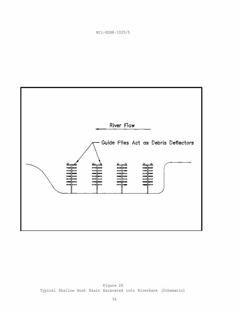
MIL-HDBK-1025/5
Figure 26Typical Shallow Boat Basin Excavated into Riverbank (Schematic)
54

MIL-HDBK-1025/5
Figure 27Typical Chained-Log Boom
for Short-Period Wave Attenuation
55

MIL-HDBK-1025/5
2.5.8 Floating Wave Attenuators. These are capable of reducing moderatewaves to acceptable proportions. Types are:
a) Chained-log boom used mainly on rivers and small lakes (seeFigure 27).
b) Floating breakwater of modular polyolefin pontoon unitssecured by timber stringers.
c) Worn out rubber tires secured together to form a continuousporous mass that floats just above the surface.
d) Air-filled mattress at the surface or suspended at somedistance below the surface to achieve out-of-phase damping.
e) Thin membrane on the surface to achieve viscous damping.
f) Random arrangements of horizontal pipes to destroy orbitalwave motion.
g) Various solid structures with void patterns designed to breakup wave motion.
h) Series of vertical diaphragms.
2.6 Design Criteria for Support Facilities
2.6.1 Utilities. For water and electrical systems, and sanitaryrequirements, refer to MIL-HDBK-1025/2, Dockside Utilities for Ship Service.The following additional utilities shall be provided:
a) An intercommunication system, such as a public address orpaging system with speakers located within easy hearing distance of every slipand support facility.
b) A central telephone switchboard in the harbor administrationbuilding.
2.6.2 Locker Boxes and Fire Equipment
2.6.2.1 Locker Boxes
a) Provide locker boxes for gear storage and for structuralsupport for fixtures.
b) Locate boxes in the knees of floating systems or in some out-of-the-way spot on decks of fixed piers.
c) Boxes shall be made of plywood, sheet metal, or fiberglass.
2.6.2.2 Firefighting Equipment
a) Chemical firefighting equipment may be used, if warranted, andplaced at 200 ft (60.1 m) intervals along each main walk.
56
MIL-HDBK-1025/5
b) Cabinets housing the equipment shall be painted red.
c) Place fire-alarm boxes at convenient locations or on nearpiers. Spacing shall conform to requirements of NFPA 87, Construction andProtection of Piers and Wharves.
2.6.3 Fuel Docks and Pump out Stations
2.6.3.1 Fuel Docks
a) Fuel docks must be rugged, support the fuel pumps, and takeaboard the lines from the buried tanks ashore.
b) Floating systems shall require flexible fuel lines leading tothe fixed lines installed in the dock.
c) Provide a quick-disconnect device at the high point in eachfuel line to prevent the siphoning of the storage tank contents into the basinin the event of a line break below the stored-fuel level.
2.6.3.2 Pump out Station. Pump out facilities are generally placed on ornear the fuel dock so that fueling and pump out can be accomplishedsuccessively at the same place. However, the pump out station should not betoo close to the fuel pumps.
2.6.4 Cleats and Fenders
2.6.4.1 General. Every dock or slip requires a set of cleats for mooringlines and fenders to cushion the impact of moored or drifting craft againstthe dock.
2.6.4.2 Cleats
a) Use cleats made of metal, either galvanized or of noncorrodingalloys, or hardwood.
b) Provide cleats of 10 or 12 in. (254 or 305 mm) length forboats up to 40 ft long (12.1 m), and 16 and 20 in. (406 and 508 mm) long forcraft up to 75 and 100 ft (22.9 and 30.5 m) long.
c) Cleats shall be securely bolted to the framework with throughbolts rather than lag bolts.
d) For cleat arrangement pattern, one cleat near the knee andone at the end of a finger (on each side) shall serve boats up to 35 ft long(10.7 m). For larger craft, provide one additional cleat per side for eachadditional 30 ft (9.1 m) or part thereof.
e) If cleats are used on loading docks or fuel docks designed forbreast mooring, they shall be sized for the largest craft and spaced at about15 ft (4.6 m) intervals. Alternatively, provide a continuous curb railsupported on blocks spaced at about 3 ft (.91 m) apart for tying mooringlines.
57

MIL-HDBK-1025/5
f) In a double-boat slip system, provide two cleats about 3 ft(.91 m) apart secured to the edge of the headwalk and centered between the twofingers.
2.6.4.3 Fenders
a) Fendering systems may include old rubber tires, discardedfirehose, or hemp hawsers of makeshift quality for the bumper elements.Special synthetic extrusion or molded shapes are preferred for small craftdockage in floating systems.
b) The preferred type of bumper stripping for the edge of afinger or dock is a synthetic extrusion that runs along the top edge of theoutside stringer with a lip extending over the top. Neoprene and butyl rubberprovide adequate weathering resistant and resilient bumper materials.
c) Molded corner bumpers, also of synthetic extrusion, provideadequate protection for smaller craft. For larger craft, use corner wheelsespecially where the finger extends all the way out to an interpier fairway(primarily on floating system).
d) Plastic-tube vertical fenders, stretched between points ofsupport or suspended from a top fastening with a heavy pendulum weight hangingbelow the lowest possible point of hull contact, are also in use.
e) Fendering of fixed piers shall usually run vertically ratherthan horizontally. Most common fenders for fixed systems are vertical timbersspaced at 8 to 10 ft (2.4 - 3.05 m) intervals along each side of a fingerpier. Size of timber shall range from 3 by 4 in. to 8 by 8 in. depending onthe size of the berthed craft.
f) Lengths shall be determined by the need to extend upward abovethe highest part of a gunwale at extreme high water and to extend below thelowest rub strake at extreme low water.
g) Pier attachments shall be adequate to resist any moment thatmight be caused by cantilever bending loads up to the design moment of thefender section.
h) Bolt heads or nut-and-bolt ends shall be countersunk into thefender pieces to avoid scoring of boat hulls.
2.6.5 Launching Hoists, Elevators, and Ways
2.6.5.1 Types. Most common types of equipment used in connection withsmall craft berthing facilities for transferring boats between land and waterare listed below:
a) Davits.
b) Forklift trucks.
c) Jib-boom cranes.
58

MIL-HDBK-1025/5
d) Lift slips.
e) Marine railways.
f) Mobile cranes.
g) Overhead rail launchers.
h) Stiff-leg derricks.
i) Straddle-truck boat hoist.
j) Vertical-lift platforms.
2.6.5.2 General Characteristics.
a) Davits are for smaller craft and lack the versatility of otherlaunching devices.
b) Marine railways entail high cost and waste of space, and lack versatility.versatility.
c) Mobile cranes, either truck-mounted or crawler-mounted, arejustifiable only where used in conjunction with some ancillary operationrequiring this equipment.
d) Vertical-lift platforms are used mainly for craft larger than25 tons.
2.6.5.3 Functional Characteristics of Different Types
a) Forklift truck has a fork ladder with the capability ofhyperextending down over a bulkhead wall to the depth required to place theforks under the hull of a floating boat. Forklifts are best suited for small-craft harbor basins with small water level fluctuation.
b) Jib-boom cranes have relatively short reach of the boom andare geared to a slower operation.
c) Three types of lift ships are in use:
1) The elevating work slip that raises the boat out of thewater so that the hull may be washed or minor damages to hulls, rudders andscrews repaired. The boat remains on a cradle or in a sling in raisedposition above the water only until the operation is completed.
2) A pair of hoists that remains as part of the berthingfacility holds the craft above the water while not in use.
3) A fixed-framework hoist that will allow the waves to passthrough the supporting legs without overturning. It is used for berthingsites along large lakes or bay shores that cannot be protected easily againstwave action.
59
MIL-HDBK-1025/5
d) Overhead-rail launchers, either monorail or duorail, functionthe same way as a straddle vehicle except that they are not mobile. Overheadrail is pushbutton-operated.
e) The still-leg derrick has the rotational problem of the jibcrane and also requires greater operator skill, and a tagline crew to controlthe craft while in the air. Derricks shall be installed for handling largercraft.
f) Straddle-truck boat hoist is limited to the boat size andstraddle clearance, and shall be used in conjunction with a launching well orparallel piers. The hoist is completely mobile.
2.6.5.4 Typical Facility. Figure 28 represents a hoist-launching facilitywith dry storage.
2.6.6 Launching Ramps
2.6.6.1 Slope. Slope of the launching ramp ranges between 12 and 15percent. Few trailered boats can be launched with a ramp slope flatter than12 percent without submerging wheel hubs of the trailer. Many trailered boatscannot be launched with hub submergence even on a 15 percent slope. Useeither a trailer-tongue extension or launch the craft with a hoist.
2.6.6.2 Surface
a) Ramp surface should be paved down to an elevation of 3 ft(.91 m) below extreme low water to ensure that trailers are not backed overthe lower end. The top should be rounded over on a 20 ft (6.1 m) verticalcurve until it becomes nearly level at about 2 ft (.61 m) above extreme highwater.
b) The wetted part shall be paved with portland cement concrete.
2.6.6.3 Approach. Nondirectional traffic circulation shall be providedwith sufficient maneuvering space, approximately 50 ft by 50 ft(15.2 - 15.2 m) adjacent to the top of the ramp.
2.6.6.4 Bottom. Bottom of the ramp shall end in a level shelf of loosegravel so that a vehicle losing brakes or traction would be stopped beforesliding deeper into the water.
2.6.6.5 General Features
a) A single-lane ramp shall not be narrower than 15 ft (4.6 m)and a multiple-lane ramp should not have raised divider strips.
b) Provide about 40 to 50 ft (12.2 - 15.2 m) maneuvering roombeyond the top of the ramp on a gentle rampward slope of about 1 on 50 forproper surface drainage.
c) Provide boarding docks, preferably, on each side of the rampand extending out into or along the sides of the basin with a total boardinglength of at least 50 feet along each ramp.
60

MIL-HDBK-1025/5
Figure 28Typical Hoist-Launching Facility With Dry Storage Yard
61

MIL-HDBK-1025/5
d) Provide sufficient protected holding area in the water justoff the ramp and boarding dock location for boats awaiting their retrievalturn during peak hours.
e) Any part of the ramp that must be placed underwater should beof precast sections. One method used successfully is 6 by 12 in.(152.4 - 305 mm) precast slabs that are a lane-width long, spaced 3 in.(76.2 mm) apart, perpendicular to the slope, and the gaps filled with gravel.Submerged ramps are also tremie-poured.
f) Provide a conveniently located washdown facility for rampsleading into saltwater or polluted waters.
2.6.6.6 Typical Layout. For layout of a typical launching ramp facility,see Figure 29.
2.6.7 Support Buildings and Ancillary Structures
2.6.7.1 Administration Building. Two or three rooms should be provided fora small installation and several rooms for headquarters of a large-sized smallcraft berthing facility. Functions and features to be handled are as follows:
a) Clerical reception office with counter for transacting theoperational business and lounge space.
b) Large record board displaying a graphical layout of theberthing facility, number or letter description of each slip and docking area,and the occupancy status.
c) Record files containing facility maintenance records, utilityservice records, employee records, and fireproof vault for their safekeeping.
d) Manager, harbormaster, or the office of the dock supervisor.
e) Communication center for relaying incoming and outgoing callsand operating the paging or public address system.
f) Restroom facilities.
g) Supplemental facilities (boardroom, coffee-break room or snackbar, engineering room, and storage room) for large installations.
2.6.7.2 Maintenance Building and Yard for Storage. For typical layout, seeFigure 30.
2.6.7.3 Boat Repair Facility. This is usually a part of, and immediatelyadjoining, a hoist or elevator. In small installations where only lightercraft are handled, four-wheel, castered dollys are used for transporting boatsfrom retrieval areas to working area. For heavier craft, large-capacityelevators are accompanied by a rail system with a transfer pit for shuntingboats on fixed-axle dollies from one track to another. A covered area with agantry crane should be provided for performing engine and hull repair.
62

MIL-HDBK-1025/5
Figure 29Layout of a Typical Launching Ramp Facility
63

MIL-HDBK-1025/5
Figure 30Typical Maintenance Building and Yard Layout
64

MIL-HDBK-1025/5
2.6.7.4 Hardware Supply Store (Optional)
2.6.7.5 Transient Housing Facilities. These are restaurants, snack bars andrecreational facilities.
2.6.7.6 Road and Walkway System. Adequate lighting shall be provided toensure smooth traffic circulation and pedestrian access to all the facilitiesin the harbor complex.
2.6.7.7 Layout of Utilities. Routing pattern for utility lines, stormdrains and sanitary sewers in the land area of the boat basin complex.
2.6.7.8 Perimeter Fencing. Perimeter fencing shall be provided with lockedentrance gates.
2.6.8 Dry Storage
2.6.8.1 Purpose. Dry storage along with wet storage is needed for lack ofsufficient space in protected waters or to keep craft dry when not in use.
2.6.8.2 Storage Criteria. Dry storage shall be limited to boats notexceeding 2 tons. Sailboats under 16 ft (4.9 m) shall be stored by hand, keepup in racks. Powerboats under 24 ft (7.3 m) shall be stored with forklifts,right side up in racks. Larger powerboats and sailboats shall be stored onspecial trailers or on adjustable cradle dollies.
2.6.8.3 Use Criteria
a) In saltwater areas, hulls of dry-stored boats should be hosedwith freshwater before storage.
b) For launching small boats from dry storage, a hinged floatingramp may be used (see Figure 31). The boat is placed on a two-wheeled dolly,and then moved down the ramp until the wheels rest against the bottom stopcurb. The boat is then pushed off into the water. Device is suitable fordinghies, small sailboats, and small outboards and where water level changesare not too great.
2.6.9 Signs. The following signs are generally provided in a small-craft
facility.
a) Welcoming sign at the entrance.
b) Direction signs where appropriate.
c) Signs designating buildings.
d) Signs for parking regulations, boat usage schedules, pier andslip designations, ramp and hoist use regulations, and sanitation andantipollution regulations.
65

MIL-HDBK-1025/5
Figure 31Typical Hinged Floating Launching Ramp Used for Small Boats
66

MIL-HDBK-1025/5
2.7 Environmental Factors and Protection
2.7.1 Snow
2.7.1.1 Factors
a) In colder regions, floating-pier systems are seriouslyaffected by excessive snow loads. Only the covered floating berths are apt tobe submerged by a heavy snowfall.
b) Most roofs of floating sheds cannot be made steep enough toensure that the snow will slide off. Roof area multiplied by 6 times theanticipated maximum snow depth in feet will give the extra weight in poundsthat is carried by flotation. If this exceeds the design live load, theamount of flotation should be increased sufficiently to support the differencewithout submergence of the flotation units.
2.7.1.2 Protection. Measures may include the following:
a) Boats berthed in the open during the snow season in coldregions shall be covered with tarpaulins, fitted canvas or reinforced plasticcovers.
b) To protect against the submergence of floating systems, boatsare removed from the water to dry storage before the winter season sets in. Acommon practice is to store the larger craft on cradles on land and cover themduring the winter season. Smaller boats are generally stored with the keel upfor better shedding of snow and rain.
2.7.2 Ice
2.7.2.1 Protection. Methods for reducing ice damage include:
a) In regions where temperature drops are not excessive andnatural freezing does not cause a thick ice sheet, ice formation can beprevented near piles and floating slips by forced convection currents. Thissystem is based on the principle that water reaches its maximum density atabout 39 °F ( 4°C) and tends to stratify in layers with the heaviest on thebottom. Forced convection of this warmer but denser water from the bottom tothe surface when the surface temperature approaches 32 ºF (0 °C) will preventor at least postpone freezing.
b) If a bubbler system is not used, sheet ice damage can bereduced or prevented by proper design provisions. Piles are driven deepenough in some materials to develop sufficient withdrawal resistance againstlifting by ice. Flotation components of floating systems are designed withrounded or tapered bottoms.
c) On rivers, estuaries and lakes, the following measures areoften expedient:
1) Pile clusters, often with sloping tops, are placed in thepath of ice floes to break them up and divert them from the harbor basin.
67

MIL-HDBK-1025/5
2) Breakwaters or jetties provide sufficient ice-impactprotection.
3) Deflecting booms made of logs or heavy timbers are usedand sited to protect the berthing area from drifting ice.
2.7.3 Hurricanes
2.7.3.1 Protection for Berthed Facilities. In regions where hurricanewinds prevail, provide pile guides, and cable or chain-anchorage systems forfloating docks. These are capable of accommodating design fluctuations ofwater level and resisting lateral wind forces.
2.7.3.2 Protection for Structural Components. Decking, roofs, and othermajor and minor provisions at dockage shall be anchored down or fastenedtogether to prevent movement and possible collision with berthed craft orharbor structures.
2.7.3.3 Design Provisions. Use of hurricane-type shutters and avoidance ofstructural projection in the design of structural components would beexpedient.
2.7.3.4 Emergency Precautions. Emergency precautions to avert or minimizethe severity of hurricane damage and to prevent injury include:
a) Remove all loose or fragile items to a protected area.
b) Open a door or window on the lee side of all buildings tobalance pressures.
c) Lash racked dinghies or other small, dry-stored boats thatcannot be moved indoors.
d) Disconnect all electrical appliances that are not neededduring the emergency.
e) Tighten or reinforce the mooring lines of all berthed craft.
f) Provide a system of lifelines for dock personnel who mustinspect the facilities during the storm.
2.7.4 Oil Spills
a) If the harbor basin has a narrow entrance, releasing acontinuous curtain of air bubbles from the bottom all the way across theentrance will keep the oil out.
b) Once spilled oil enters the basin, removal is accomplished byemploying floating booms, oil skimmers, and straw absorption.
68

MIL-HDBK-1025/5
2.7.5 Floods
2.7.5.1 Nature of Damage. Flood damage, at harbor sites on or near ariver, is in the form of debris accumulation and collision of floating objectswith structures.
2.7.5.2 Protection. Provide training wall as protection against debris andshoaling hazards.
2.8 Summary of Common Design Problems
2.8.1 Problems. The problems most commonly reported for small-craftberthing facilities are listed in paras. 2.8.1.1 through 2.8.1.6.
2.8.1.1 Ice
a) Windblowing or movement by currents of ice floes constitutes aserious regional problem. Free-floating cake ice is the greatest cause of icedamage.
b) If feasible, piles shall be driven butt-end down where iceformation is anticipated.
c) In a floating-pier system, the greatest damage is caused byice crushing the floats. Forced-convection or bubbler systems are effectivefor ice prevention.
2.8.1.2 Corrosive Environment
a) Failure of low-level lighting systems due to sea spray in highwind conditions is a problem.
b) Frequency of corrosion of water valves by seawaternecessitates the selection of T-type faucet handles over the circular type.
c) Use of untreated wood for decking or structural members offixed piers.
2.8.1.3 Fuel Dispensing
a) Fueling boats during extreme low water levels at fixed-pierstations.
b) Reliability of fuel line connections to floating-pierstations.
2.8.1.4 Floating-Pier Systems
a) Difficulty of adjusting chain or cable anchorages during waterlevel fluctuation cycles and tendency of these systems to drift beyonddesirable limits.
b) Time and difficulty involved in seasonal removal and storageof floating systems at locations requiring winter security.
69

MIL-HDBK-1025/5
2.8.1.5 Shoaling of Channels and Basins
a) It constitutes a difficult maintenance-dredging problem.
b) Detailed surveys of site bathymetry, suited to the site,should always be acquired.
2.8.1.6 Boat-Wake Problems. Enforcement of speed regulations for craftoperated near berthing areas is essential.
70

MIL-HDBK-1025/5
REFERENCES
AWPB Standard MPL for Softwood Lumber, Timber and Plywood Pressure Treated forMarine (Saltwater) Exposure, American Wood Preservers Bureau, P.O. Box 6085,2772 S. Randolph Street, Arlington, VA 22206.
Construction and Protection of Piers and Wharves, NFPA 87, National FireProtection Association (NFPA), Inc., Batterymarch Park, Quincy, MA 02269.
Militarv Specification MIL-P-40619, Plastic Material, Cellular, Polystyrene(For Buoyancy Applications) available at the Naval Publications and FormsCenter, 5801 Tabor Avenue, Philadelphia, PA 19120.
NAVFACENGCOM Design Manuals and Military Handbooks. Government agenciesand the private sector may obtain standardization documents(specifications/handbooks) from the Commanding Officer, Naval Publications andForms Center (NPFC), 5801 Tabor Avenue, Philadelphia, PA 19120. Governmentagencies must order design manuals/P-pubs using the Military StandardRequisitioning and Issue Procedure (MILSTRIP) system from NPFC. The privatesector must write to NPFC, Cash Sales, Code 1051, 5801 Tabor Avenue,Philadelphia, PA 19120.
MIL-HDBK-1025/1
MIL-HDBK-1025/2
MIL-HDBK-1025/4
MIL-HDBK-1025/6
DM-26.1
DM-26.2
DM-26.6
Piers and Wharves
Dockside Utilities for Ship Service
Seawalls, Bulkheads, and Quaywalls
General Criteria for Waterfront Construction
Harbors
Coastal Protection
Mooring Design Physical and Empirical Data
Shore Protection Manual, Volumes I and II, U.S. Army Coastal EngineeringResearch Center, 1984, available at the U.S. Government Printing Office,Washington, DC 20402.
Tide Prediction Tables, National Oceanic and Atmospheric Administration,National Ocean Service Distribution Branch, 6501 Lafayette Ave., Riverdale,MD 20737-1199, (301) 436-6990.
79

MIL-HDBK-1025/5
GLOSSARY
Accretion. May be either natural or artificial. Natural accretion is thebuildup of land, solely by the action of the forces of nature, on a beach bydeposition of waterborne or airborne material. Artificial accretion is asimilar buildup of land such as that formed by a breakwater, jetty, or groin.Also Aggradation.
Anchor Pile. A pile or column that is an integral part of waterfrontstructure, whose primary function is to keep the structure firmly in place,having been driven into earth for this purpose.
Ancillary Facilities. Installation or services provided at a harbor site thatcomplement the harbor's operations, but are not essential to harborfunctioning per se.
Apron. Clear area around perimeter of a dock for access, parking, storage,and working space.
Armor. An outer layer of large stone or concrete armor units whose functionis to ensure the integrity of an embankment, jetty, or breakwater forprotection against wave action or currents.
Attenuate. To lessen the amplitude (magnitude of the displacement of a wavefrom a mean value) of waves or surge.
Auxiliary Power. Means of propelling a craft that is not the primarilydesigned means, e.g., an engine-driven propeller on a sailboat.
Bank. The rising ground bordering a river, lake, or sea; of a river orchannel, designated as right or left as it would appear facing downstream.
Basin. Boat. A naturally or artificially enclosed or nearly enclosed harborarea for small craft.
Bathymetry. The measurement of depths of water in seas, lakes, or oceans;also information derived for such measurements. Also Hydrography orSoundings.
Beach. The zone of unconsolidated material that extends landward from the lowwater line to the point where there is marked change in material orphysiographic form, or to the line of permanent vegetation. The seaward limitof a beach, unless otherwise specified, is the MWL.
Beach Erosion. The carrying away of beach materials by wave action, tidalcurrents, littoral currents, or wind.
Bearing Boards. The wooden members that transmit the deck loads to the floatsin some floating-pier systems.
Bedding Layers. The first and the lowest layer of gravel or stone that actsas a bearing layer for larger stones or armor units placed upon it. It alsofunctions as a filter layer for the material beneath the structure.
80
MIL-HDBK-1025/5
Berm. A nearly horizontal part of the beach or backshore formed by thedeposit of material by wave action. Some beaches have no berm; others haveone or more.
Berth. Area where a boat may be secured to a fixed or floating structure andleft unattended.
Berthing Area. Area of a harbor set aside for berthing boats (vessels) atdocks and open anchorages.
Boat. Any type of surface craft that may be berthed in a small-craft harbor.
Breakwater. A structure protecting a shore area, harbor, anchorage, or basinfrom waves.
Brow. A type of bridge providing access to a berthed boat or vessel forembarking and disembarking personnel.
Bulkhead. A structure designed to retain or prevent sliding of earth andconsisting of a vertical wall, sometimes supplemented by an anchor system. Asecondary purpose is to protect the upland against damage from wave action.
Bulkhead Line. A line which establishes limits outside of which continuoussolid-fill construction is not permitted.
Buoy. A float, especially a floating object moored to the bottom to mark achannel, anchor, shoal, rock, etc.
Cantilever. A projecting beam, pile, or structural member that resists or iscapable of resisting a transverse load applied to the part projecting beyondits last point of support.
Cap. The finished structural member topping off a wall or bulkhead, providingstrength, protection, and continuity to the wall or bulkhead.
Cleat. A wooden or metal mooring fitting having two diverging horizontal armsto which mooring lines from boats are attached.
Cofferdam. A temporary wall which serves to exclude water from a sitenormally under water so as to facilitate foundation installation or similarwork.
Current. A flow of water.
Davit. A device for raising, storing, and lowering a boat.
Diaphragm Breakwater. A comparatively thin, impervious wall, membrane, orstructure designed to resist wave penetration, usually a secondary defensestructure.
Dock. A fixed or floating decked structure against which a boat may beberthed either temporarily or indefinitely.
81

MIL-HDBK-1025/5
Dolphin. A cluster of batter pilings joined at the top, and placed near piersand wharves, or alongshore, to guide vessels into their moorings; to fendboats away from structures, shoals, or the shore; and for anchorage offloating piers.
Down drift. The direction of predominant movement of littoral materials.
Draft. Depth of craft hull below the waterline.
Eddy Current. A circular movement of water formed on the side of a maincurrent. Eddies may be formed at points where the main stream passesprojecting obstructions or where two adjacent currents flow counter to eachother.
Estuary. (1) The part of a river that is affected by tides.
(2) The region near a river mouth in which the freshwater of theriver mixes with the saltwater of the sea.
Fairway. Parts of a waterway that are open and unobstructed for navigation.
Fender. A protective bumper or framed system placed against the edge of adock, designed to prevent damage caused by impact of berthing or berthedboats.
Filter. The underlayer of small rock or gravel or sand that permits properseepage and dissipation or distribution of water beneath or behind a structure
or there retained material towall or riprap slope without allowing the earthescape.
Finger Pier. A smaller pier structure attached (usually perpendicular) to thehead walk of a multislip pier; provided to facilitate access to the berthedcraft.
Freeboard. The distance from the waterline to main deck or gunwale.
Gangway. A pedestrian or handcart bridge affording access from shore orshore- connected fixed pier to a floating structure (sometimes called brow).
Groin. A shore protection structure built, usually perpendicular to theshoreline, to trap littoral drift or retard erosion of the shore.
Guide Piles. Piles in a floating dock system that resist the horizontaldisplacement of the system but allow and guide its vertical movement withchanges in the level of the water surface.
Gunwale. The upper edge of the side of a ship or a boat.
Harbor. A sheltered area of the sea or ocean, easily accessible to maritimeroutes in which vessels may seek refuge, transfer cargo, and undergo repairand refueling.
Head walk. The main walkway on a multislip pier; supports utility lines,lighting system, firefighting equipment, and locker boxes.
82

MIL-HDBK-1025/5
Hurricane. Intense tropical cyclone in which winds spiral inward toward a lowpressure core with maximum surface wind velocities that equal or exceed 80 mph(70 knots) for several minutes or longer at some points.
Jetty. On open seacoasts, a structure extending into a body of water, anddesigned to prevent shoaling of a channel by littoral processes, and to directand confine the stream or tidal flow. Jetties are built at the mouth of ariver or tidal inlet to help maintain and stabilize a channel.
Keel. The principal bottom structural element of a craft extending along thecenterline for the full length of the craft.
Lee. (1) The part or side sheltered or turned away from wind or waves,
(2) The quarter or region toward which the wind blows (chieflynautical).
Leeward. The direction toward which the wind is blowing; the direction towardwhich waves are traveling.
Littoral Drift. The sedimentary material moved in the littoral zone under theaction of waves and currents.
Littoral Transport. The movement of littoral drift in the littoral zone bywaves and currents. It includes movement parallel (long-shore transport) andperpendicular (on-shore transport) to the shore.
Operational Launching. Boat launching on a routine in-and-out basis asdistinguished from initial or seasonal launching.
Overtopping. Flow of water over the top of a structure, such as a breakwater,as a result of wave runup or surge action.
Pier. A dock that is built from the shore out into the harbor and used forberthing and mooring craft (a structure, usually, of open construction).
Profile. Beach. The intersection of the ground surface with a vertical plane;may extend from the top of the dune line to the seaward limit of sandmovement.
Pump out Station. A facility for removal of sanitary wastes from a boat'sholding tank or head.
Revetment. A facing of stone, concrete, or other material built to protect ascarp, embankment, or shore structure against erosion by wave action orcurrents.
Riprap. A layer, facing, or protective mound of stones randomly placed toprevent erosion, scour, or sloughing of structure or embankment; also thestone so used.
Riser. A vertical pipe, post, or support extending above deck level tosupport utility outlets and other facilities.
83

MIL-HDBK-1025/5
Rub Strake. A longitudinal rib or protective strip running along the hull ofa craft to function as a bumper.Rubble Mound. A mound of random-shaped and randomly-placed stones protectedwith a cover layer of selected stones or specially shaped concrete armorunits.
Runup. The rush of water up a structure or beach on the breaking of a wave.The magnitude of runup is the vertical height above still-water level that therush of water reaches.
Scend. The sinkage of a craft in the trough of a wave.
Screw. A propeller on any type of craft.
Sheet pile. A pile with a generally flat cross-section to be driven into theground or seabed and meshed or interlocked with like members to form adiaphragm, wall, or bulkhead.
Shoreline. The intersection of a specified plane of water with the shore orbeach.
Shoal. Become shallow gradually (v.). A detached elevation of the sea bottomcomprising any material except rock or coral, and which may endanger surfacenavigation (n.).
Slip. A space between two piers for craft berthing.
Small Craft. Shallow draft vessels such as work boats, rescue boats, harborand pilot launches, special service craft, and survey boats.
Squat. The vertical downward displacement of a craft under power with respectto its position in the water when not underway.
Stringer. The relatively long, main horizontal beam that supports the deck ofa fixed pier or dock between bearing points. In a floating structure, thecontinuous beam (usually, along the sides) that joins a series of floatingmodules.
Surge. Wave motion with a period intermediate between that of a ordinarywind- generated wave and wave caused by tide, say, from 30 seconds to 60minutes. It is of low height, usually less than 0.3 feet.
Swell. Wind-generated waves that have traveled out of their generating area;characteristically represents a more regular and long period and has flattercrests than waves within their fetch.
Tidal Range. Difference in height between consecutive high and low waters.
Tide. Periodic rise and fall of the water that results from gravitationalattraction of the moon and sun, and other astronomical bodies acting upon thefloating earth.
Trailing Floating Slips. Floating (usually, multiboat) slips that alignthemselves with the prevailing river current. They do not require guidepiles.
84

MIL-HDBK-1025/5
Training Wall. A wall or jetty designed to direct or stabilize current flow.
Transfer Bridge. A short-span bridge between boat and dock for transfer ofrailroad cars and other vehicles.
Tremie-Poured Concrete. Concrete placed underwater in such a manner thatthere is no free drop of the concrete through the water. This is accomplishedby pouring through a pipe or placing with special bottom-dump bucket.
Uplift. The upward water pressure on the base of a structure.
Waterline. The place where land and sea meet. This plane shifts with tidalchange or other fluctuations in the water level.
Wave Attenuation. Reduction of wave height or amplitude for any reason as thewave is propagated from one area to another.
Wave Breaker. A device that absorbs a large amount of wave energy withrespect to the amount it reflects or transmits.
Wave Energy. The theoretical capacity of a wave to do work.
Wharf. A dock oriented approximately parallel to shore and used for berthingor mooring craft.
CUSTODIANNAVY - YD
PREPARING ACTIVITYNAVY - YD
PROJECT NO.FACR-0258
85 *U.S. GOVERNMENT PRINTING OFFICE: 1989 - 604-033/11262