Unifence TMSaw Guide 30Capacity - Delta Machinery · Saw; 10 Tilting Arbor Saw and 10 Unisaw in...
20
INSTRUCTIONMANUAL Unifence TM Saw Guide 30"Capacity (Model 36-905) REVISED: 10-27-98 PA RT NO. 422-27-655-0053 'Delta International Machinery Corp. 1998
-
Upload
truonglien -
Category
Documents
-
view
262 -
download
3
Transcript of Unifence TMSaw Guide 30Capacity - Delta Machinery · Saw; 10 Tilting Arbor Saw and 10 Unisaw in...
INSTRUCTIONMANUAL
UnifenceT MSaw Guide30"Capacity
(Model 36-905)
REVISED: 10-27-98 PA RT NO. 422-27-655-0053'Delta International Machinery Corp. 1998
2
TABLE OF CONTENTSINTRODUCTION...............................................................................................................................................................2
UNPACKING.....................................................................................................................................................................3
CONSTRUCTING UNIFENCE TABLE.............................................................................................................................3
ASSEMBLING LEGS AND FRONT TABLE SUPPORT..................................................................................................4
ASSEMBLING TABLE ADAPTER PLATE TO SAW TABLE..........................................................................................5
ASSEMBLING UNIFENCE TABLE TO SAW ..................................................................................................................6
ASSEMBLING UNIFENCE GUIDE RAIL TO TABLE......................................................................................................7
ASSEMBLING REAR EXTENSION WING SUPPORT B A R.........................................................................................12
ASSEMBLING CURSOR TO UNIFENCE BODY ..........................................................................................................13
ASSEMBLING UNIFENCE BODY TO GUIDE RAIL.....................................................................................................13
ASSEMBLING FENCE TO UNIFENCE BODY..............................................................................................................14
FENCE OPERATION......................................................................................................................................................15
RIPPING WITH THE UNIFENCE ...................................................................................................................................16
ADJUSTING FENCE PARALLEL TO MITER GAGE SLOTS.......................................................................................17
ADJUSTING FENCE 90 DEGREES TO TABLE ...........................................................................................................17
ADJUSTING CLAMPING ACTION OF FENCE LOCKING HANDLE...........................................................................17
RIPPING ON LEFT SIDE OF SAW BLADE ..................................................................................................................18
USING THE FENCE AS A CUT-OFF GAGE .................................................................................................................18
USING AUXILIARY WOOD FACING ON THE UNIFENCE...........................................................................................19
CONSTRUCTING A PUSH STICK.................................................................................................................................19
PARTS, SERVICE OR WARRANTY ASSISTANCE......................................................................................................20
W ARRANTY ...................................................................................................................................................................20
INTRODUCTIONThe model 36-905, 30 capacity UnifenceT M Saw Guide can be assembled to the Delta 10 Contractor sSaw; 10 Tilting Arbor Saw and 10 Unisaw in addition to other makes of table saws. The 36-905UnifenceT M Saw Guide includes the fence, carriage assembly, front guide rail, table frame, legs and shelfsupport. The accessory 34-914 table is not included with the 36-905 UnifenceTM Saw Guide and must beordered separately or a similar table must be constructed by following the instructions in this manual.
3
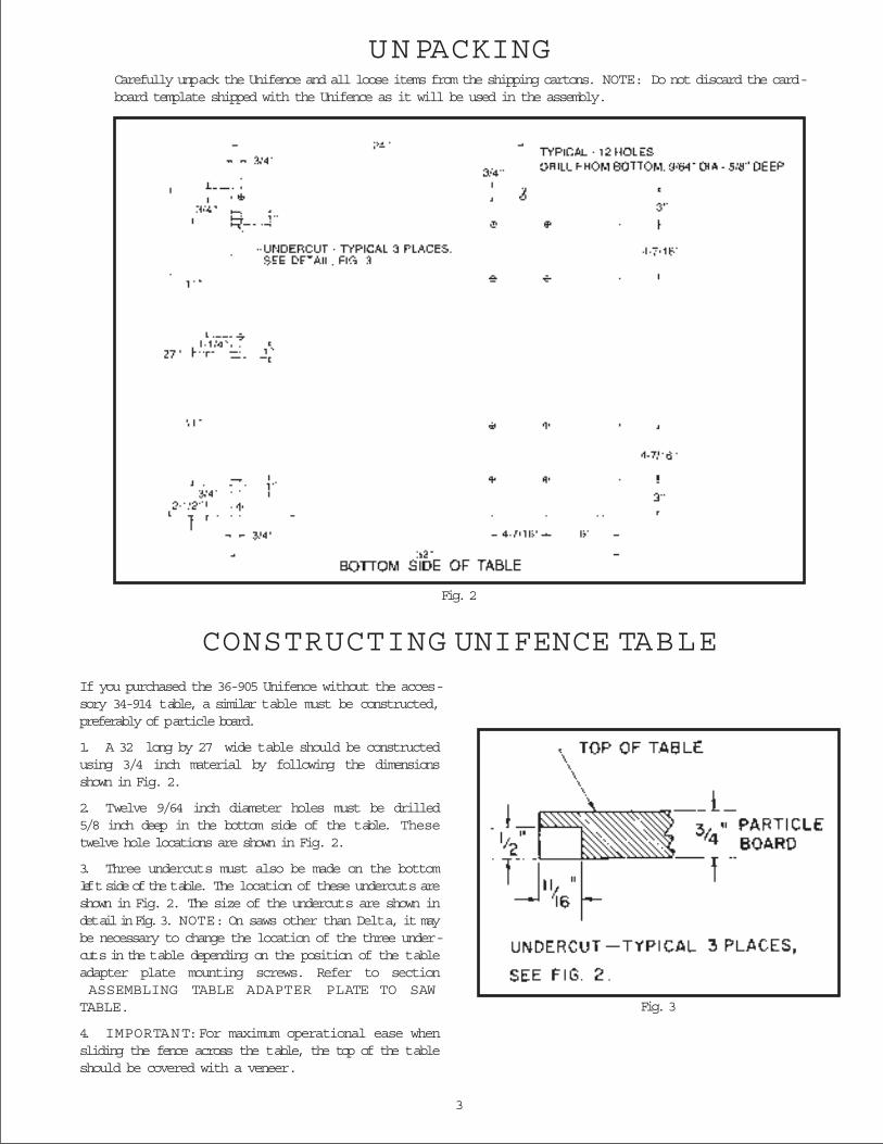
UNPACKINGCarefully unpack the Unifence and all loose items from the shipping cartons. NOTE: Do not discard the card-board template shipped with the Unifence as it will be used in the assembly.
If you purchased the 36-905 Unifence without the acces-sory 34-914 table, a similar table must be constructed,preferably of particle board.
1. A 32 long by 27 wide table should be constructedusing 3/4 inch material by following the dimensionsshown in Fig. 2.
2. Twelve 9/64 inch diameter holes must be drilled5/8 inch deep in the bottom side of the table. Thesetwelve hole locations are shown in Fig. 2.
3. Three undercuts must also be made on the bottomleft side of the table. The location of these undercuts areshown in Fig. 2. The size of the undercuts are shown indetail in Fig. 3. NOTE: On saws other than Delta, it maybe necessary to change the location of the three under-cuts in the table depending on the position of the tableadapter plate mounting screws. Refer to sectionASSEMBLING TABLE ADAPTER PLATE TO SAW
TABLE.
4. IMPORTANT: For maximum operational ease whensliding the fence across the table, the top of the tableshould be covered with a veneer.
Fig. 2
CONSTRUCTING UNIFENCE TABLE
Fig. 3
4
Fig. 4
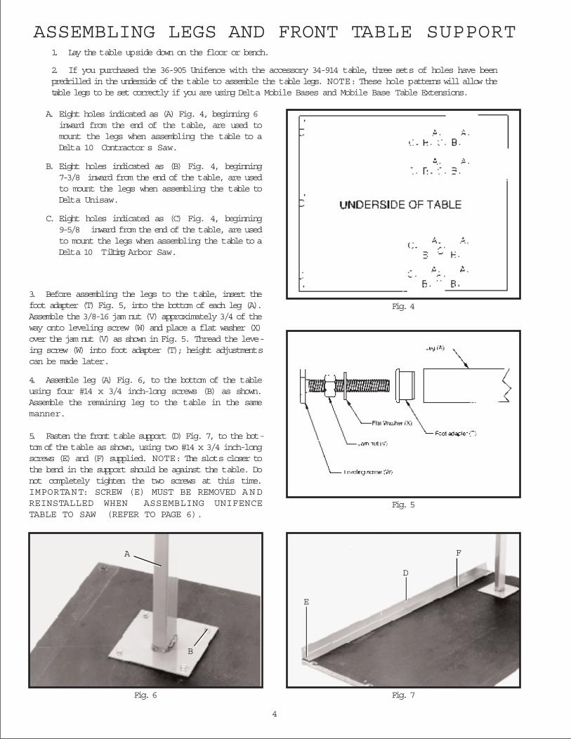
ASSEMBLING LEGS AND FRONT TABLE SUPPORT1. Lay the table upside down on the floor or bench.
2. If you purchased the 36-905 Unifence with the accessory 34-914 table, three sets of holes have beenpredrilled in the underside of the table to assemble the table legs. NOTE: These hole patterns will allow thetable legs to be set correctly if you are using Delta Mobile Bases and Mobile Base Table Extensions.
A. Eight holes indicated as (A) Fig. 4, beginning 6inward from the end of the table, are used tomount the legs when assembling the table to aDelta 10 Contractor s Saw.
B. Eight holes indicated as (B) Fig. 4, beginning7-3/8 inward from the end of the table, are usedto mount the legs when assembling the table toDelta Unisaw.
C. Eight holes indicated as (C) Fig. 4, beginning9-5/8 inward from the end of the table, are usedto mount the legs when assembling the table to aDelta 10 Tilting Arbor Saw.
Fig. 5
Fig. 7Fig. 6
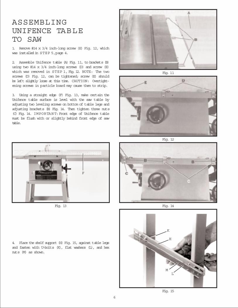
3. Before assembling the legs to the table, insert thefoot adapter (T) Fig. 5, into the bottom of each leg (A).Assemble the 3/8-16 jam nut (V) approximately 3/4 of theway onto leveling screw (W) and place a flat washer (X)over the jam nut (V) as shown in Fig. 5. Thread the leve-ing screw (W) into foot adapter (T); height adjustmentscan be made later.
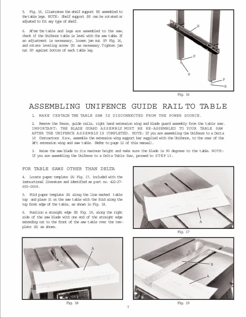
4. Assemble leg (A) Fig. 6, to the bottom of the tableusing four #14 x 3/4 inch-long screws (B) as shown.Assemble the remaining leg to the table in the samemanner.
5. Fasten the front table support (D) Fig. 7, to the bot-tom of the table as shown, using two #14 x 3/4 inch-longscrews (E) and (F) supplied. NOTE: The slots closer tothe bend in the support should be against the table. Donot completely tighten the two screws at this time.IMPORTANT: SCREW (E) MUST BE REMOVED A N DREINSTALLED WHEN ASSEMBLING UNIFENCETABLE TO SAW (REFER TO PAGE 6).
A
B
E
D
F

5
Fig. 8
Fig. 9
ASSEMBLING TABLE ADAPTER PLATETO S AW TABLE
Fig. 10
1. Assemble three brackets (A) Fig. 8, to table adapterplate (B) using three 1/4-20 x 3/4 inch-long carriagebolts, flat washers and hex nuts (C). Do not completelytighten hardware at this time as adjustments must bemade.
FOR DELTA TABLE SAWS ONLY
2. Assemble table adapter plate (B) Fig. 9, to the rightside of the saw table using three 7/16-20 x 1 inch-longhex head screws (D) and lockwashers. NOTE: Beforetightening screws (D), place a straight edge (E) on thesaw table, and make certain the top of adapter plate (B)is level with or slightly below the surface of the sawtable. Also, make certain the front of adapter plate (B)does not extend out past the front edge of the saw table.IMPORTANT: FOR DELTA S AWS ONLY, PROCEEDWITH SECTION ASSEMBLING UNIFENCE TABLETO SAW .
FOR TABLE SAWS OTHER THAN DELTA
3. Assemble table adapter plate (B) Fig. 10, to the rightside of the saw table as shown using three 3/4 inchscrews, lockwashers and hex nuts (D), (not supplied).IMPORTANT: If the pre-drilled holes in adapter plate (B)do not line up with the holes in the saw table, new holesmust be drilled in adapter plate (B) and/or saw table.NOTE: Do not drill any hole to fasten adapter plate (B)Fig. 10, to the saw table that will be located less than twoinches from either end of the adapter plate.
4. Before tightening three screws (D) Fig. 10, place astraight edge on the saw table and make certain the topof adapter plate is level with or slightly below the surfaceof the saw table, refer to Fig. 9. Also, make certain frontof adapter plate (B) Fig. 10, does not extend out past thefront edge of the saw table.
6
Fig. 11
Fig. 12
Fig. 14Fig. 13
Fig. 15
F
K
H
ML
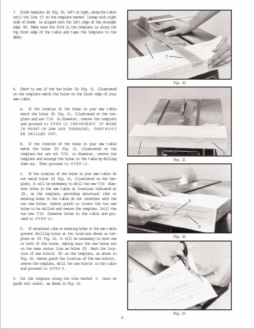
ASSEMBLINGUNIFENCE TABLETO SAW1. Remove #14 x 3/4 inch-long screw (E) Fig. 12, whichwas installed in STEP 5, page 4.
2. Assemble Unifence table (A) Fig. 11, to brackets (B)using two #14 x 3/4 inch-long screws (D) and screw (E)which was removed in STEP 1, Fig. 12. NOTE: The twoscrews (D) Fig. 12, can be tightened; screw (E) shouldbe left slightly loose at this time. CAUTION: Overtight-ening screws in particle board may cause them to strip.
3. Using a straight edge (F) Fig. 13, make certain theUnifence table surface is level with the saw table byadjusting two leveling screws on bottom of table legs andadjusting brackets (B) Fig. 14. Then tighten three nuts(C) Fig. 14. IMPORTANT: Front edge of Unifence tablemust be flush with or slightly behind front edge of sawtable.
4. Place the shelf support (H) Fig. 15, against table legsand fasten with U-bolts (K), flat washers (L), and hexnuts (M) as shown.
7
Fig. 16
5. Fig. 16, illustrates the shelf support (H) assembled tothe table legs. NOTE: Shelf support (H) can be rotated oradjusted to fit any type of shelf.
6. After the table and legs are assembled to the saw,check if the Unifence table is level with the saw table. Ifan adjustment is necessary, loosen jam nut (P) Fig. 16,and rotate leveling screw (R) as necessary.Tighten jamnut (P) against bottom of each table leg.
ASSEMBLING UNIFENCE GUIDE RAIL TO TABLE1. MAKE CERTAIN THE TABLE SAW IS DISCONNECTED FROM THE POWER SOURCE.
2. Remove the fence, guide rails, right hand extension wing and blade guard assembly from the table saw.IMPORTANT: THE BLADE GUARD ASSEMBLY MUST BE RE-ASSEMBLED TO YOUR TABLE SAWAFTER THE UNIFENCE ASSEMBLY IS COMPLETED. NOTE: If you are assembling the Unifence to a Delta10 Contractors Saw, assemble the extension wing support bar supplied with the Unifence, to the rear of theleft extension wing and saw table. (Refer to page 12 of this manual).
3. Raise the saw blade to its maximum height and make sure the blade is 90 degrees to the table. NOTE:If you are assembling the Unifence to a Delta Table Saw, proceed to STEP 13.
Fig. 19Fig. 18
FOR TABLE SAWS OTHER THAN DELTA
4. Locate paper template (A) Fig. 17, included with theinstructional literature and identified as part no. 422-27-655-0009.
5. Fold paper template (A) along the line marked tabletop and place it on the saw table with the fold along thetop front edge of the table, as shown in Fig. 18.
6. Position a straight edge (B) Fig. 19, along the rightside of the saw blade with one end of the straight edgeextending out to the front of the saw table over the tem-plate (A) as shown.
H
P
RP
R
Fig. 17
A
A
A
B
8
Fig. 20
Fig. 21
Fig. 22
Fig. 23
7. Slide template (A) Fig. 20, left or right, along the tableuntil the line (C) on the template marked lineup with rightside of blade is aligned with the left edge of the straightedge (B). Make sure the fold in the template is along thetop front edge of the table and tape the template to thetable.
8. Check to see if the two holes (D) Fig. 21, illustratedon the template match the holes on the front edge of yoursaw table.
A. If the location of the holes in your saw tablematch the holes (D) Fig. 21, illustrated on the tem-plate and are 7/16 in diameter, remove the templateand proceed to STEP 13. IMPORTANT: IF HOLESIN FRONT OF SAW ARE THREADED, THEY MUSTBE DRILLED OUT.
B. If the location of the holes in your saw tablematch the holes (D) Fig. 21, illustrated on thetemplate but are not 7/16 in diameter, remove thetemplate and enlarge the holes in the table by drillingthem out. Then proceed to STEP 13.
C. If the location of the holes in your saw table donot match holes (D) Fig. 21, illustrated on the tem-plate, it will be necessary to drill two new 7/16 diam-eter holes in the saw table at locations indicated at(D), on the template, providing structural ribs orexisting holes in the table do not interfere with thetwo new holes. Center punch to locate the two newholes to be drilled and remove the template. Drill thetwo new 7/16 diameter holes in the table and pro-ceed to STEP 13.
D. If structural ribs or existing holes in the saw tableprevent drilling holes at the locations shown on tem-plate at (D) Fig. 22, it will be necessary to move oneor both of the holes, making sure the new holes areon the same center line as holes (D). Mark the loca-tion of new hole(s) (E) on the template, as shown inFig. 22. Center punch the location of the new hole(s),remove the template, drill the new hole(s) in the tableand proceed to STEP 9.
9. Cut the template along the line marked 0 (zero onguide rail scale), as shown in Fig. 23.
C
BA
D D
D
E
9
Fig. 24
Fig. 25
Fig. 26
Fig. 27 Fig. 28
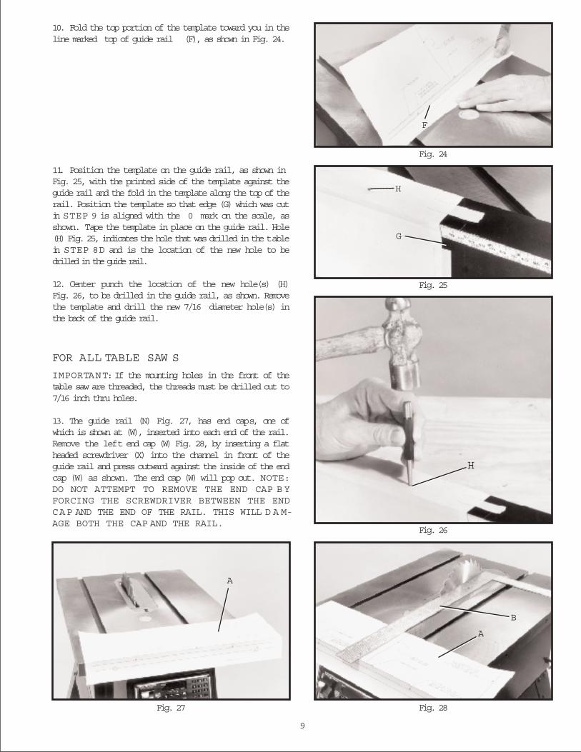
10. Fold the top portion of the template toward you in theline marked top of guide rail (F), as shown in Fig. 24.
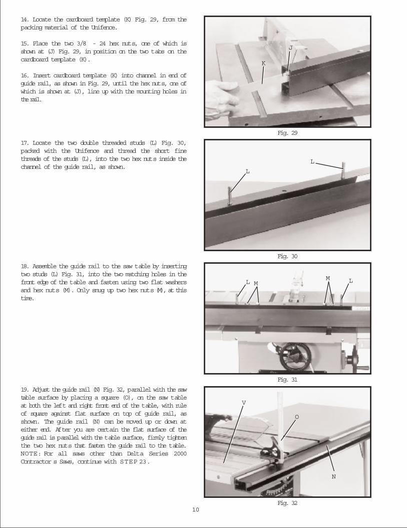
11. Position the template on the guide rail, as shown inFig. 25, with the printed side of the template against theguide rail and the fold in the template along the top of therail. Position the template so that edge (G) which was cutin STEP 9 is aligned with the 0 mark on the scale, asshown. Tape the template in place on the guide rail. Hole(H) Fig. 25, indicates the hole that was drilled in the tablein STEP 8D and is the location of the new hole to bedrilled in the guide rail.
12. Center punch the location of the new hole(s) (H)Fig. 26, to be drilled in the guide rail, as shown. Removethe template and drill the new 7/16 diameter hole(s) inthe back of the guide rail.
FOR ALL TABLE SAW S
IMPORTANT: If the mounting holes in the front of thetable saw are threaded, the threads must be drilled out to7/16 inch thru holes.
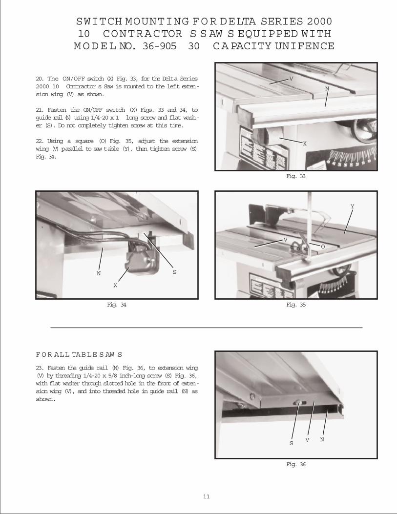
13. The guide rail (N) Fig. 27, has end caps, one ofwhich is shown at (W), inserted into each end of the rail.Remove the left end cap (W) Fig. 28, by inserting a flatheaded screwdriver (X) into the channel in front of theguide rail and press outward against the inside of the endcap (W) as shown. The end cap (W) will pop out. NOTE:DO NOT ATTEMPT TO REMOVE THE END CAP B YFORCING THE SCREWDRIVER BETWEEN THE ENDCAP AND THE END OF THE RAIL. THIS WILL D A M-AGE BOTH THE CAP AND THE RAIL.
F
H
G
H
A
B
A
10
Fig. 29
Fig. 30
Fig. 31
Fig. 32
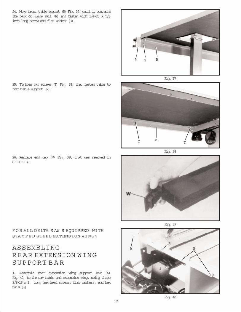
14. Locate the cardboard template (K) Fig. 29, from thepacking material of the Unifence.
15. Place the two 3/8 - 24 hex nuts, one of which isshown at (J) Fig. 29, in position on the two tabs on thecardboard template (K).
16. Insert cardboard template (K) into channel in end ofguide rail, as shown in Fig. 29, until the hex nuts, one ofwhich is shown at (J), line up with the mounting holes inthe rail.
17. Locate the two double threaded studs (L) Fig. 30,packed with the Unifence and thread the short finethreads of the studs (L), into the two hex nuts inside thechannel of the guide rail, as shown.
18. Assemble the guide rail to the saw table by insertingtwo studs (L) Fig. 31, into the two matching holes in thefront edge of the table and fasten using two flat washersand hex nuts (M). Only snug up two hex nuts (M), at thistime.
19. Adjust the guide rail (N) Fig. 32, parallel with the sawtable surface by placing a square (O), on the saw tableat both the left and right front end of the table, with ruleof square against flat surface on top of guide rail, asshown. The guide rail (N) can be moved up or down ateither end. After you are certain the flat surface of theguide rail is parallel with the table surface, firmly tightenthe two hex nuts that fasten the guide rail to the table.NOTE: For all saws other than Delta Series 2000Contractor s Saws, continue with STEP 23.
K
J
L
L
L MM L
O
N
V
11
SWITCH MOUNTING FOR DELTA SERIES 200010 CONTRACTOR S S AW S EQUIPPED WITHMODEL NO. 36-905 30 CAPACITY UNIFENCE
Fig. 33
Fig. 34 Fig. 35
20. The ON/OFF switch (X) Fig. 33, for the Delta Series2000 10 Contractor s Saw is mounted to the left exten-sion wing (V) as shown.
21. Fasten the ON/OFF switch (X) Figs. 33 and 34, toguide rail (N) using 1/4-20 x 1 long screw and flat wash-er (S). Do not completely tighten screw at this time.
22. Using a square (O) Fig. 35, adjust the extensionwing (V) parallel to saw table (Y), then tighten screw (S)Fig. 34.
V
X
N
X
N S
Y
VO
Fig. 36
FOR ALL TABLE S AW S
23. Fasten the guide rail (N) Fig. 36, to extension wing(V) by threading 1/4-20 x 5/8 inch-long screw (S) Fig. 36,with flat washer through slotted hole in the front of exten-sion wing (V), and into threaded hole in guide rail (N) asshown.
S V N
12
FOR ALL DELTA S AW S EQUIPPED WITHSTAMPED STEEL EXTENSION WINGS
ASSEMBLINGREAR EXTENSION WINGSUPPORT B A R
1. Assemble rear extension wing support bar (A)Fig. 40, to the saw table and extension wing, using three3/8-16 x 1 long hex head screws, flat washers, and hexnuts (B).
B B
A
Fig. 37
Fig. 38
Fig. 39
Fig. 40
24. Move front table support (R) Fig. 37, until it contactsthe back of guide rail (N) and fasten with 1/4-20 x 5/8inch-long screw and flat washer (S).
25. Tighten two screws (T) Fig. 38, that fasten table tofront table support (R).
26. Replace end cap (W) Fig. 39, that was removed inSTEP 13.
SN R
T RT

13
Fig. 41
Fig. 42
Fig. 43
Fig. 45Fig. 44
FOR ALL TABLE S AW S
ASSEMBLING CURSORTO UNIFENCE BODY1. Remove two screws and flat washers (A) Fig. 41,and assemble the cursor (B) to the Unifence body (C).Replace the two screws and flat washers (A).
2. Fig. 42, illustrates the cursor (B) assembled to theUnifence body. Adjustment to the cursor (B) will be madelater.
ASSEMBLING UNIFENCEBODY TO GUIDE RAIL1. Turn fence body (A) Fig. 43, upside down and lay iton a table or bench. Push handle (B) in against fencebody. Make certain the surface (C) of clamp bracket isparallel to the face (D) of the fence body, and thatthe inside edge (E) of the clamp bracket is parallel tosurface (F) of the fence body. Turn handle (B) Fig. 43, ifnecessary.
2. Place fence body (A) Fig. 44, onto the guide rail asshown, making sure clamp bracket is inserted into chan-nel (G) on rail. Notice that the clamp handle (B) is turnedto the left indent position.
3. Turn handle (B) Fig. 45, to the right indent position asshown. This will prevent fence clamp from sliding out ofthe channel (G).
B
C
A
B
D A
B C EF
A
BG
BG

14
Fig. 46
Fig. 47
Fig. 48
Fig. 49
4. Lock fence body (A) to the guide rail by pushingdown on handle (B) as shown in Fig. 46.
ASSEMBLING FENCETO UNIFENCE BODY1. The fence (A) can be assembled to clamp plate (B)in either the horizontal position as shown in Fig. 47, orthe vertical position as shown in Fig. 48. Make certain thetwo lock knobs (C), are loose and slide fence (A) ontoclamp plate (B) as shown. Then tighten the two lockknobs (C).
2. For most normal ripping operations, the bottom ofthe fence should be positioned slightly above the tablesurface. Loosen two lock knobs (C) Fig. 49, and place athin object such as a ruler (D) between the table andfence, as shown. Then tighten two lock knobs (C).
A
B
A
B
C
CD
15
Fig. 50
Fig. 51
Fig. 52
Fig. 54Fig. 53
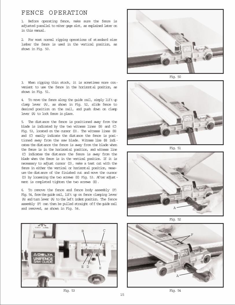
FENCE OPERATION1. Before operating fence, make sure the fence isadjusted parallel to miter gage slot, as explained later onin this manual.
2. For most normal ripping operations of standard sizelumber the fence is used in the vertical position, asshown in Fig. 50.
3. When ripping thin stock, it is sometimes more con-venient to use the fence in the horizontal position, asshown in Fig. 51.
4. To move the fence along the guide rail, simply lift upclamp lever (A), as shown in Fig. 52, slide fence todesired position on the rail, and push down on clamplever (A) to lock fence in place.
5. The distance the fence is positioned away from theblade is indicated by the two witness lines (B) and (C)Fig. 53, located on the cursor (D). The witness lines (B)and (C) easily indicate the distance the fence is posi-tioned away from the saw blade. Witness line (B) indi-cates the distance the fence is away from the blade whenthe fence is in the horizontal position, and witness line(C) indicates the distance the fence is away from theblade when the fence is in the vertical position. If it isnecessary to adjust cursor (D), make a test cut with thefence in either the vertical or horizontal position, meas-ure the distance of the finished cut and move the cursor(D) by loosening the two screws (E) Fig. 53. After adjust-ment is completed tighten the two screws (E).
6. To remove the fence and fence body assembly (F)Fig. 54, from the guide rail, lift up on fence clamping lever(A) and turn lever (A) to the left indent position. The fenceassembly (F) can then be pulled straight off the guide railand removed, as shown in Fig. 54. A
F
A
EDE
CB
16
Fig. 55
Fig. 56
Fig. 57
Fig. 58
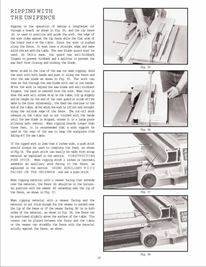
RIPPING WITHTHE UNIFENCE
Ripping is the operation of making a lengthwise cutthrough a board, as shown in Fig. 55, and the rip fence(A) is used to position and guide the work. One edge ofthe work rides against the rip fence while the flat side ofthe board rests on the table. Since the work is pushedalong the fence, it must have a straight edge and makesolid contact with the table. The saw blade guard must beused. On Delta saws, the guard has anti-kickbackfingers to prevent kickback and a splitter to prevent thesaw kerf from closing and binding the blade.
Never stand in the line of the saw cut when ripping. Holdthe work with both hands and push it along the fence andinto the saw blade as shown in Fig. 55. The work canthen be fed through the saw blade with one or two hands.After the work is beyond the saw blade and anti-kickbackfingers, the hand is removed from the work. When this isdone the work will either stay on the table, tilt up slightlyand be caught by the end of the rear guard or slide off thetable to the floor. Alternately, the feed can continue to theend of the table, after which the work is lifted and broughtalong the outside edge of the fence. The cut-off stockremains on the table and is not touched with the handsuntil the saw blade is stopped, unless it is a large pieceallowing safe removal. When ripping boards longer thanthree feet, it is recommended that a work support beused at the rear of the saw to keep the workpiece fromfalling off the saw table.
If the ripped work is less than 4 inches wide, a push stickshould always be used to complete the feed, as shownin Fig. 56. The push stick can easily be made from scrapmaterial as explained in the section CONSTRUCTINGPUSH STICK. When ripping stock 2 inches or narrower,assemble an auxiliary wood facing to the fence, asexplained in the section USING AUXILIARY W O O DFACING ON THE UNIFENCE and use a push stick.
When ripping material with a veneer facing that extendsover the material, the fence (A) should be in the horizon-tal position with the veneer (B) extending over the lip ofthe fence, as shown in Fig. 57.
When ripping material with a veneer facing and thematerial is not thick enough for the veneer to extend overthe lip of the fence or if the veneer facing (B) is on bothsides of the material, as shown in Fig. 58, the fence canbe positioned slightly above the surface of the table. Theveneer can be placed between the fence and the tableor the veneer can straddle the fence with the materialsolidly against the fence, as shown.
A
B
A
B
17
Fig. 59
Fig. 60
Fig. 61
Fig. 62
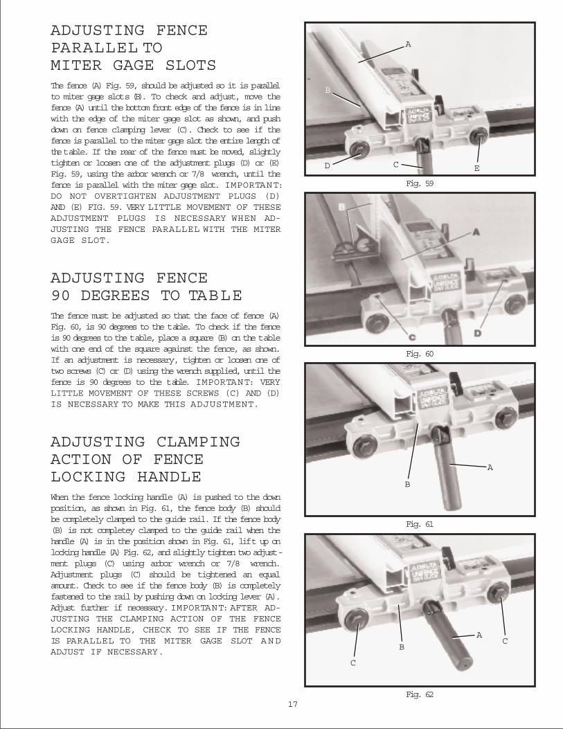
ADJUSTING FENCEPARALLEL TOMITER GAGE SLOTSThe fence (A) Fig. 59, should be adjusted so it is parallelto miter gage slots (B). To check and adjust, move thefence (A) until the bottom front edge of the fence is in linewith the edge of the miter gage slot as shown, and pushdown on fence clamping lever (C). Check to see if thefence is parallel to the miter gage slot the entire length ofthe table. If the rear of the fence must be moved, slightlytighten or loosen one of the adjustment plugs (D) or (E)Fig. 59, using the arbor wrench or 7/8 wrench, until thefence is parallel with the miter gage slot. IMPORTANT:DO NOT OVERTIGHTEN ADJUSTMENT PLUGS (D)AND (E) FIG. 59. VERY LITTLE MOVEMENT OF THESEADJUSTMENT PLUGS IS NECESSARY WHEN AD-JUSTING THE FENCE PARALLEL WITH THE MITERGAGE SLOT.
ADJUSTING FENCE90 DEGREES TO TABLEThe fence must be adjusted so that the face of fence (A)Fig. 60, is 90 degrees to the table. To check if the fenceis 90 degrees to the table, place a square (B) on the tablewith one end of the square against the fence, as shown.If an adjustment is necessary, tighten or loosen one oftwo screws (C) or (D) using the wrench supplied, until thefence is 90 degrees to the table. IMPORTANT: VERYLITTLE MOVEMENT OF THESE SCREWS (C) AND (D)IS NECESSARY TO MAKE THIS ADJUSTMENT.
ADJUSTING CLAMPINGACTION OF FENCELOCKING HANDLEWhen the fence locking handle (A) is pushed to the downposition, as shown in Fig. 61, the fence body (B) shouldbe completely clamped to the guide rail. If the fence body(B) is not completey clamped to the guide rail when thehandle (A) is in the position shown in Fig. 61, lift up onlocking handle (A) Fig. 62, and slightly tighten two adjust-ment plugs (C) using arbor wrench or 7/8 wrench.Adjustment plugs (C) should be tightened an equalamount. Check to see if the fence body (B) is completelyfastened to the rail by pushing down on locking lever (A).Adjust further if necessary. IMPORTANT: AFTER AD-JUSTING THE CLAMPING ACTION OF THE FENCELOCKING HANDLE, CHECK TO SEE IF THE FENCEIS PARALLEL TO THE MITER GAGE SLOT A N DADJUST IF NECESSARY.
A
B
D C E
B
A
AC
B
C
18Fig. 66 Fig. 67
Fig. 65
Fig. 64
Fig. 63
USING THE FENCE A S A CUT-OFF G A G E
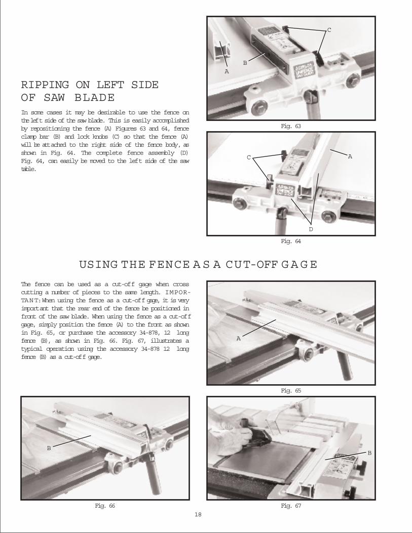
RIPPING ON LEFT SIDEOF SAW BLADEIn some cases it may be desirable to use the fence onthe left side of the saw blade. This is easily accomplishedby repositioning the fence (A) Figures 63 and 64, fenceclamp bar (B) and lock knobs (C) so that the fence (A)will be attached to the right side of the fence body, asshown in Fig. 64. The complete fence assembly (D)Fig. 64, can easily be moved to the left side of the sawtable.
The fence can be used as a cut-off gage when crosscutting a number of pieces to the same length. IMPOR-TANT:When using the fence as a cut-off gage, it is veryimportant that the rear end of the fence be positioned infront of the saw blade. When using the fence as a cut-offgage, simply position the fence (A) to the front as shownin Fig. 65, or purchase the accessory 34-878, 12 longfence (B), as shown in Fig. 66. Fig. 67, illustrates atypical operation using the accessory 34-878 12 longfence (B) as a cut-off gage.
C
AB
A
D
C
A
BB
19
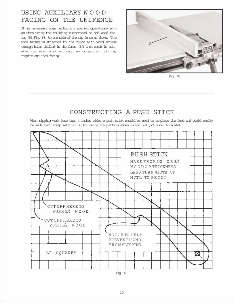
Fig. 68
CONSTRUCTING A PUSH STICKWhen ripping work less than 4 inches wide, a push stick should be used to complete the feed and could easilybe made from scrap material by following the pattern shown in Fig. 69 (not shown to scale).
Fig. 69
PUSH STICKMAKE FR O M 1/2 O R 3/4W O O D O R THICKNESSLESS THAN WIDTH OFM ATL. TO BE CUT
CUT OFF HERE TOPUSH 1/4 W O O D
CUT OFF HERE TOPUSH 1/2 W O O D
1/2 SQUARES
NOTCH TO HELPPREVENT HANDF R O M SLIPPING
USING AUXILIARY W O O DFACING ON THE UNIFENCEIt is necessary when performing special operations suchas when using the moulding cutterhead to add wood fac-ing (A) Fig. 68, to one side of the rip fence as shown. Thewood facing is attached to the fence with wood screwsthrough holes drilled in the fence. 3/4 inch stock is suit-able for most work although an occasional job mayrequire one inch facing.
A
20
Delta will repair or replace, at its expense and at its option, any Delta machine, machine part, or machineaccessory which in normal use has proven to be defective in workmanship or material, provided that thecustomer returns the product prepaid to a Delta factory service center or authorized service station withproof of purchase of the product within two years and provides Delta with reasonable opportunity to ver-ify the alleged defect by inspection. Delta may require that electric motors be returned prepaid to a motormanufacturer s authorized station for inspection and repair or replacement. Delta will not be responsiblefor any asserted defect which has resulted from normal wear, misuse, abuse or repair or alteration madeor specifically authorized by anyone other than an authorized Delta Service facility or representative.Under no circumstances will Delta be liable for incidental or consequential damages resulting from defec-tive products. This warranty is Delta s sole warranty and sets forth the customer s exclusive remedy, withrespect to defective products; all other warranties, express or implied, whether of merchantability, fitnessfor purpose, or otherwise, are expressly disclaimed by Delta.
Two Year Limited Warranty
Delta Machinery
Printed in U.S.A.
PARTS, SERVICE O R W ARRANTY ASSISTANCEAll Delta Machines and accessories are manufactured tohigh quality standards and are serviced by a network offactory service centers and authorized service stationslisted in your owner s manual. To obtain additional infor-
mation regarding your Delta quality product or to obtainparts, service or warranty assistance, please call or faxDeltas toll-free hotline number.
Delta maintains a modern,efficient Parts DistributionCenter, maintaining aninventory of over 15,000parts located in Memphis,Tennessee.
Highly qualified and exper-ienced Customer ServiceRepresentatives are standingby to assist you on weekdaysfrom 7:00 A.M. to 6:00 P.M.Memphis time.
Memphis, TN 381184290 Raines Road
Phone: (901) 363-8800
800-223-PARTFAX: 800-535-6488