UNIERSITY OF NAIROBImechanical.uonbi.ac.ke/sites/default/files/cae/engineering...UNIERSITY OF...
56
i UNIERSITY OF NAIROBI DEPARTMENT OF MECHANICAL AND MANUFACTURING ENGINEERING FINAL YEAR PROJECT PROJECT NO. JMO/01/2011 TITLE: DESIGN OF BRAKEPAD FRICTION MATERIAL COMPILED BY: JOEL JEREMIAH GACHOKI : F18/1853/2006 MARANGU DICKSON KATHENYA : F18/1838/2006 SUPERVISED BY: DR. JULIUS M.OGOLA A final year project submitted in partial fulfillment of the requirements for the award of the degree of Bachelor of science in Mechanical Engineering
-
Upload
nguyenliem -
Category
Documents
-
view
215 -
download
1
Transcript of UNIERSITY OF NAIROBImechanical.uonbi.ac.ke/sites/default/files/cae/engineering...UNIERSITY OF...
i
UNIERSITY OF NAIROBI
DEPARTMENT OF MECHANICAL AND MANUFACTURING ENGINEERING
FINAL YEAR PROJECT
PROJECT NO. JMO/01/2011
TITLE: DESIGN OF BRAKEPAD FRICTION MATERIAL
COMPILED BY:
JOEL JEREMIAH GACHOKI : F18/1853/2006
MARANGU DICKSON KATHENYA : F18/1838/2006
SUPERVISED BY: DR. JULIUS M.OGOLA
A final year project submitted in partial fulfillment of the requirements for the award of the degree of Bachelor of science in Mechanical Engineering
ii
DECLARATION
Students
This report is our original work and has not been published or presented for
award of degree in any university there before.
Signed……………………………………… Date……………………………………………………
JOEL JEREMIAH GACHOKI
Signed...………………………………… Date…………………………………………………
MARANGU DICKSON KATHENYA
Supervisor
This report has been submitted by the above students for examination with
my approval as a university lecturer and supervisor of the project.
Signed………………………………….. Date ………………………………….
Dr. JULIUS M. OGOLA

iii
DEDICATION
To our families and friends for their abundant and relentless love.
We respect you and above all we love you.

iv
ACKNOWLEDGEMENT
The undertaking and completion of this research work was made possible by a number of
people to whom we are profoundly grateful to.
We are particularly indebted to our supervisor Dr. J.M. Ogola for his guidance,
encouragement and constructive criticism which has immensely contributed to the
successful completion of this project.
We would wish to give thanks to mechanical and manufacturing engineering department
staff for their in-time support and also the department of physics Chiromo campus for their
support.
Our gratitude also goes to Mr. Mwitari from KIRDI and Mr. Tioni from KEBS for their
continued support throughout the project.
We are eternally grateful to our parents for their support and encouragement, but most
important for their prayers.
We appreciate and wish to extend our best wishes to our fellow colleagues and friends for
their invaluable support and encouragement throughout the entire period.
Lastly but most important, we thank God for abilities and opportunity he has bestowed
upon us. Glory is to Him.
v
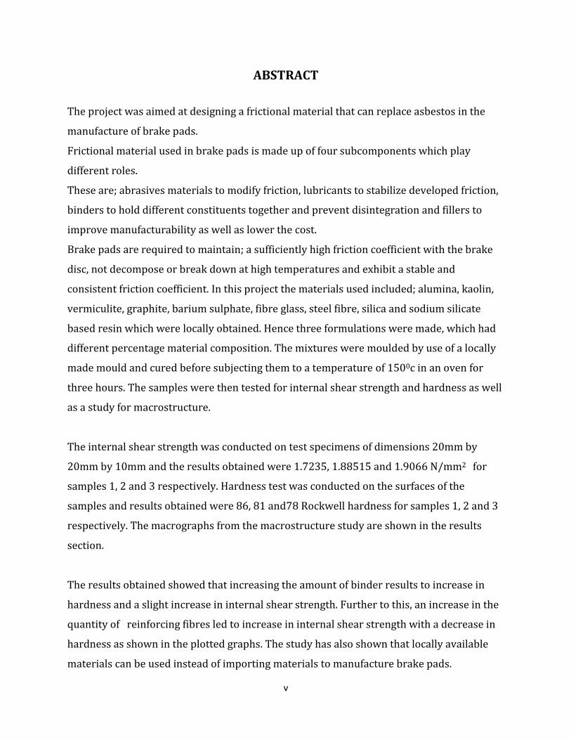
ABSTRACT
The project was aimed at designing a frictional material that can replace asbestos in the
manufacture of brake pads.
Frictional material used in brake pads is made up of four subcomponents which play
different roles.
These are; abrasives materials to modify friction, lubricants to stabilize developed friction,
binders to hold different constituents together and prevent disintegration and fillers to
improve manufacturability as well as lower the cost.
Brake pads are required to maintain; a sufficiently high friction coefficient with the brake
disc, not decompose or break down at high temperatures and exhibit a stable and
consistent friction coefficient. In this project the materials used included; alumina, kaolin,
vermiculite, graphite, barium sulphate, fibre glass, steel fibre, silica and sodium silicate
based resin which were locally obtained. Hence three formulations were made, which had
different percentage material composition. The mixtures were moulded by use of a locally
made mould and cured before subjecting them to a temperature of 1500c in an oven for
three hours. The samples were then tested for internal shear strength and hardness as well
as a study for macrostructure.
The internal shear strength was conducted on test specimens of dimensions 20mm by
20mm by 10mm and the results obtained were 1.7235, 1.88515 and 1.9066 N/mm2 for
samples 1, 2 and 3 respectively. Hardness test was conducted on the surfaces of the
samples and results obtained were 86, 81 and78 Rockwell hardness for samples 1, 2 and 3
respectively. The macrographs from the macrostructure study are shown in the results
section.
The results obtained showed that increasing the amount of binder results to increase in
hardness and a slight increase in internal shear strength. Further to this, an increase in the
quantity of reinforcing fibres led to increase in internal shear strength with a decrease in
hardness as shown in the plotted graphs. The study has also shown that locally available
materials can be used instead of importing materials to manufacture brake pads.
vi
TABLE OF CONTENTS DECLARATION .............................................................................................................................................. i
DEDICATION ............................................................................................................................................... iii
ACKNOWLEDGEMENT ............................................................................................................................... iv
ABSTRACT .................................................................................................................................................... v
CHAPTER ONE ............................................................................................................................................. 1
INTRODUCTION ........................................................................................................................................... 1
1.1 Background ........................................................................................................................................ 1
1.2 Problem statement ............................................................................................................................ 2
1.3 Objectives ........................................................................................................................................... 2
CHAPTER TWO ............................................................................................................................................ 3
LITERATURE REVIEW ................................................................................................................................ 3
2.1 Brakes ................................................................................................................................................. 3
2.2 Braking system .................................................................................................................................. 3
2.3 Drum brake ........................................................................................................................................ 5
2.4 Disc brake .......................................................................................................................................... 6
2.5 Disc rotor ........................................................................................................................................... 6
2.6 Calliper ............................................................................................................................................... 7
2.7 Brake pads ......................................................................................................................................... 7
2.7.1 Steel backing plate ..................................................................................................................... 8
2.7.2 Wear indicator ............................................................................................................................ 9
2.7.3 Frictional lining .......................................................................................................................... 9
2.8 Categories of frictional lining ........................................................................................................... 9
2.8.1 Metallic pads ................................................................................................................................ 9
2.8.2 Asbestos pads ............................................................................................................................ 10
2.8.3 Ceramics pads ............................................................................................................................ 10
2.8.4 Semi-metallic pads ..................................................................................................................... 10
2.9 Constituents of brake pad frictional lining .................................................................................... 11

vii
2.9.1 Reinforcing materials ............................................................................................................... 12
2.9.2 Fillers ......................................................................................................................................... 14
2.9.3 Binders ...................................................................................................................................... 15
2.9.4 Frictional additives .................................................................................................................. 17
CHAPTER THREE....................................................................................................................................... 19
FRICTIONAL LINING MATERIALS ............................................................................................................ 19
3.1 Materials requirement .................................................................................................................... 19
3.2 Materials used in the frictional lining formulation ....................................................................... 20
3.2.1 Reinforcing materials ............................................................................................................... 20
3.2.2 Fillers ......................................................................................................................................... 21
3.2.3 Frictional additives .................................................................................................................. 23
3.2.4 Binders ...................................................................................................................................... 24
3.3 Choice of sample composition ........................................................................................................ 26
CHAPTER FOUR ......................................................................................................................................... 31
MANUFACTURING PROCESS .................................................................................................................... 31
4.1 Materials preparation ..................................................................................................................... 31
4.3 Moulding process ............................................................................................................................ 33
CHAPTER FIVE ........................................................................................................................................... 36
LAB TESTING ............................................................................................................................................. 36
5.1 Hardness testing .............................................................................................................................. 36
5.2 Shear strength ................................................................................................................................. 38
5.3 Macrostructure study ..................................................................................................................... 41
CHAPTER SIX ............................................................................................................................................. 43
DISCUSSION, CONCLUSION AND RECOMMENDATION.......................................................................... 43
6.1 Discussion ........................................................................................................................................ 43
6.2 Conclusion........................................................................................................................................ 44
6.3 Recommendations ........................................................................................................................... 45
REFERENCES ............................................................................................................................................. 46

1
CHAPTER ONE
INTRODUCTION
1.1 Background
In the past asbestos was used to manufacture brake pads. Asbestos became increasingly
popular among brake pad manufacturers because of its sound absorption, average tensile
strength, and its resistance to heat, electrical and chemical damage However, since 1970s,
asbestos had gained widespread acknowledgement as a carcinogen .This is because
inhalation of asbestos fibers can cause serious illnesses, including malignant lung cancer,
mesothelioma (a formerly rare cancer strongly associated with exposure to amphibole
asbestos) and asbestosis (a type of pneumoconiosis).Other asbestos-related diseases
include;
Asbestos warts: caused when the sharp fibers lodge in the skin and are overgrown causing
benign callus-like growths.
Pleural plaques: discrete fibrous or partially calcified thickened area which can be seen on
X-rays of individuals exposed to asbestos. Although pleural plaques are themselves
asymptomatic, in some patients this develops into pleural thickening.
Diffuse pleural thickening: similar to above and can sometimes be associated with
asbestosis. Usually no symptoms shown but if exposure is extensive, it can cause lung
impairment.
This led to the use and development of other materials which could take the place of
asbestos in the manufacture of brake pads in automotive industry. These other materials
which are currently in use include; metals, ceramics, carbon and organic materials.
However these materials have different advantages and disadvantages when solely used to
construct a brake pad. Hence more research is being carried on a combination of different
materials so as to optimize the performance requirements.
2
1.2 Problem statement
From the previous project research undertaken by Kevin Loye Wadeya and Peter Ochieng
Ombewa, three brake pads were constructed and tested in the laboratories. The tests
carried out were internal shear strength test and the Rockwell hardness test.
Macrostructure study was also carried out. The results obtained from the Rockwell
hardness test were satisfactory since they met the standard required by the Kenya Bureau
of Standards. However the values of internal shear strength for the three samples
constructed were below the value required by Kenya Bureau of Standards. As a result,
internal shear strength was the major drawback, hence more research needed to be carried
out to improve the pads. In this research the aim was to use the locally available asbestos
free materials to construct a brake pad with improved internal shear strength and
optimum friction coefficient while maintaining the hardness.
1.3 Objectives
The objectives of the project are as follows
(i) To design a heat resistant brake pad that has optimum friction coefficient and
internal shear strength
(ii) To use locally available materials that will not cause environmental pollution as
well as health problems.
(iii) To construct and test the designed brake pad so as to determine its feasibility
for use in motor vehicles.

3
CHAPTER TWO
LITERATURE REVIEW
2.1 Brakes
A brake is a device which inhibits motion. Most brakes use friction to convert kinetic
energy into heat, though other methods of energy conversion may be employed. For
example regenerative braking converts much of the energy to electrical energy, which may
be stored for later use. Other methods convert kinetic energy into potential energy in such
stored forms as pressurized air or pressurized oil. Still other braking methods even
transform kinetic energy into different forms, for example by transferring the energy to a
rotating flywheel. In automobiles friction brakes are commonly used.
A friction brake is a type of an automotive brake that slows or stops a vehicle by
converting kinetic energy into heat energy, via friction. The braking heat is stored in the
brake drum or disc while braking, then conducted to the air gradually.
2.2 Braking system
The modern automotive brake system has been refined for over 100 years and has become
extremely dependable and efficient. The typical brake system consists of disk brakes in
front and either disk or drum brakes in the rear connected by a system of tubes and hoses
that link the brake at each wheel to the master cylinder. When one steps on the brake
pedal, he or she pushes against a plunger in the master cylinder, which forces hydraulic oil
(brake fluid) through a series of tubes and hoses to the braking unit at each wheel. On a
disk brake, the fluid from the master cylinder is forced into a caliper where it presses
against a piston. The piston in-turn squeezes the two brake pads against the rotor that is
attached to the wheel forcing it to slow down.

4
A picture illustrating how brake works
With drum brakes, fluid is forced into the wheel cylinder, which pushes the brake shoes out
so that the friction linings are pressed against the drum, which is attached to the wheel,
causing the wheel to stop.
A friction brake in automobile may either be a drum brake or a disc brake.

5
2.3 Drum brake
A drum brake is a brake in which friction is caused by a set of brake shoes that press
against the inner surface of a rotating drum. The drum is connected to the rotating road
wheel hub.
A picture of a brake drum

6
2.4 Disc brake
This is a brake in which the pads pinch a rotating disc. The disc brake is a device for
slowing or stopping the rotation of a road wheel. A brake disc, usually made of cast iron or
ceramic, is connected to the wheel or the axle. To stop the wheel, friction material in the
form of brake pads (mounted in a device called a brake caliper) is forced mechanically,
hydraulically or pneumatically against both sides of the disc. Friction causes the disc and
attached wheel to slow or stop. A disc brake assembly consists of a
• Cast iron disc or the disc rotor that rotates with the wheel
• Caliper assembly attached to the steering knuckle
• Friction materials (disc pad) that are mounted to the caliper assembly
When hydraulic pressure is applied through the caliper piston, it forces the inside pad to
contact the disc. As pressure increases the caliper moves and causes the pad to contact the
disc. Braking force is generated by friction between the disc pads as they are squeezed
against the disc rotor.
The friction surface is constantly exposed to air ensuring good heat dissipation minimizing
brake fade. It also allows for self cleaning as dust and water are thrown off reducing friction
differences
2.5 Disc rotor
The disc rotor is made of grey cast iron and is either solid or ventilated. The ventilated disc
rotor consists of a wider disc with cooling fins cast through the middle to ensure good
cooling. Proper cooling prevents fading and ensures longer pad life. Some ventilated rotors
have spiral fins which creates more air flow and better cooling .Spiral finned rotors are
directional and are mounted on a specific side of the vehicle.

7
2.6 Calliper
The caliper houses one to four pistons and is mounted to the Torque plate and steering
knuckle or wheel carrier. There are two caliper designs; floating caliper and fixed caliper
2.7 Brake pads
Brake pads are a component of disk brakes used in automotive and other applications.
Brake pads are steel backing plates with friction material bound to the surface that faces
the disk brake rotor.
Brake pads convert the kinetic energy of the car to thermal energy by friction. Two brake
pads are contained in the brake caliper with their friction surfaces facing the rotor. When
the brakes are hydraulically applied, the caliper clamps or squeezes the two pads together
into the spinning rotor to slow/stop the vehicle. When a brake pad is heated by contact
with a rotor, it transfers small amounts of friction material to the disc, turning it dull gray.
The brake pad and disc (both now with friction material), then "stick" to each other,
providing the friction that stops the vehicle.
Although it is commonly thought that the pad material contacts the metal of the disc to
stop the car, the pads work with a very thin layer of their own material and generate a
semi-liquid friction boundary that creates the actual braking force. Friction can be divided
into two parts: Adhesive and abrasive.
Depending on the properties of the material of the pad and the disc, the configuration and
the usage, pad and disc wear rates will vary considerably. The properties that determine
material wear involve trade-offs between performance and longevity. The friction
coefficient for most standard pads will be in the region of 0 .40 when used with cast iron
discs. Racing pads with high iron content designed for use with cast iron brake discs reach
0.55 to 0 .60 which gives a very significant increase in braking power and high temperature
performance. High iron content racing pads wear down discs very quickly and usually
when the pads are worn out so are the discs.
8
Different brake design applications require different kinds of friction materials, several
considerations are weighed in development of brake pads; the coefficient of friction must
remain constant over a wide range of temperatures .The brake pads must not wear out
rapidly nor should they wear the disc rotor, should withstand the highest temperatures
without fading and it should be able to do all these without any noise. Materials that make
up the brake pad include; friction modifiers, powdered metal, binder, fillers and curing
agents. Friction modifiers such as graphite and cashew nuts shells alter the friction
coefficient. Powdered metals such as lead, zinc, brass and Al increase a materials resistant
to heat fade .Binders are the glues that hold the friction materials together. Phenolic resin is
the most common binder in current use. Fillers are added to friction materials in small
quantities to accomplish specific purposes such as rubber chips to reduce brake noise. The
brake pad material is bonded to a stamped steel backing plate with a high temperature
adhesive to which heat and pressure are applied to cure the assembly .A slit is provided on
the face of the pad to indicate the allowable limit of pad wear and provide a path for brake
dust and gas to escape .A metal plate or in some applications multiple plates called anti
squeal shims are provided on the piston side of the pad to minimize brake squeal. Various
springs and clips are used to reduce rattle as well as reduce brake noise. Shims and plates
should be inspected for wear and rust and can be reused when replacing pads. Fresh
approved grease should be applied to the shims prior to installation.
The brake pad consists of the following parts
2.7.1 Steel backing plate
This part is usually fabricated from low-carbon steels. The function of the backing plates
is to transmit the force from the caliper pistons to the friction material. It may also
contain retention features such as holes or serrated edges to provide a better anchor
point for the friction material.

9
2.7.2 Wear indicator
Since all friction materials gradually wear out, a wear indicator is fitted to each pair of
brake pads to inform the driver that replacement is required. In most cases a simple
steel spring is riveted to the brake pad backing plate to serve this purpose. When the
friction material wears to the point that replacement is necessary, the spring will contact
the rotor, emitting a high-pitched squeal.
2.7.3 Frictional lining
The brake pad friction lining is the primary wear element for the brake system. This is a
part of the brake pad that is designed to contact with the rotor, converting kinetic
energy into heat and as a result, it gradually wears out until it needs replacing. Of all the
brake pad parts, the friction material is arguably the most critical from a high-
performance perspective.
2.8 Categories of frictional lining Frictional linings can be categorized according to the material composition used in the
manufacture. The categories include
2.8.1 Metallic pads
These pads are typically made of iron, copper, steel and graphite all mixed together and
bonded to form the pad material.
The pads are cost-effective and durable. They are also good at transferring the heat
generated by friction with the brake rotors .However, being made of metal the pads are
very hard. This makes them to cause more wear on the brake rotors.
They do not work well when cold, they are noisy and dust

10
2.8.2 Asbestos pads
Asbestos was the best choice material in the manufacture of brake pads. This is because of
its good properties such as low thermal conductivity and ability to withstand high
temperatures which are essential in brake pads. Asbestos was also readily available.
However, in the early 1980s it was discovered to be carcinogenic and was capable of casing
Asbestosis and Mesothelioma.
2.8.3 Ceramics pads
These pads are made of ceramics compounds which are a composition of about 15 percent
metal fibres and other ingredients such as fillers binders and lubricants. The various fillers
and lubricants help dampen vibration and noise and hence these pads are quiet in
operation,
These pads wear less, transfer heat better because of metal fibres and are lighter in weight
2.8.4 Semi-metallic pads
These pads consist of about 40 percent metallic fibres and other ingredients which include
fillers binders and lubricants. They also include pads that are carbon based
Semi-metallic pads are strong, conduct heat away from rotors, generate noise and are
abrasive enough to increase rotor wear.
11
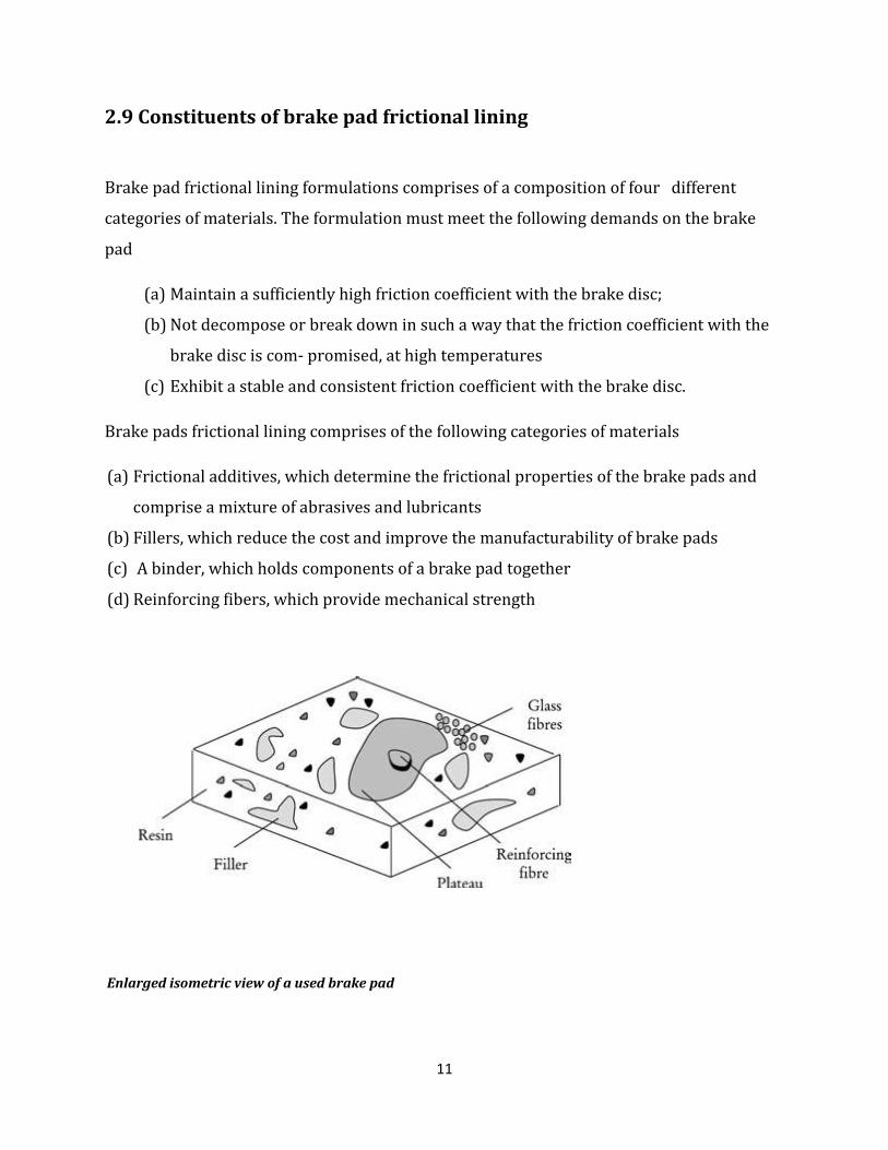
2.9 Constituents of brake pad frictional lining
Brake pad frictional lining formulations comprises of a composition of four different
categories of materials. The formulation must meet the following demands on the brake
pad
(a) Maintain a sufficiently high friction coefficient with the brake disc;
(b) Not decompose or break down in such a way that the friction coefficient with the
brake disc is com- promised, at high temperatures
(c) Exhibit a stable and consistent friction coefficient with the brake disc.
Brake pads frictional lining comprises of the following categories of materials
(a) Frictional additives, which determine the frictional properties of the brake pads and
comprise a mixture of abrasives and lubricants
(b) Fillers, which reduce the cost and improve the manufacturability of brake pads
(c) A binder, which holds components of a brake pad together
(d) Reinforcing fibers, which provide mechanical strength
Enlarged isometric view of a used brake pad
12
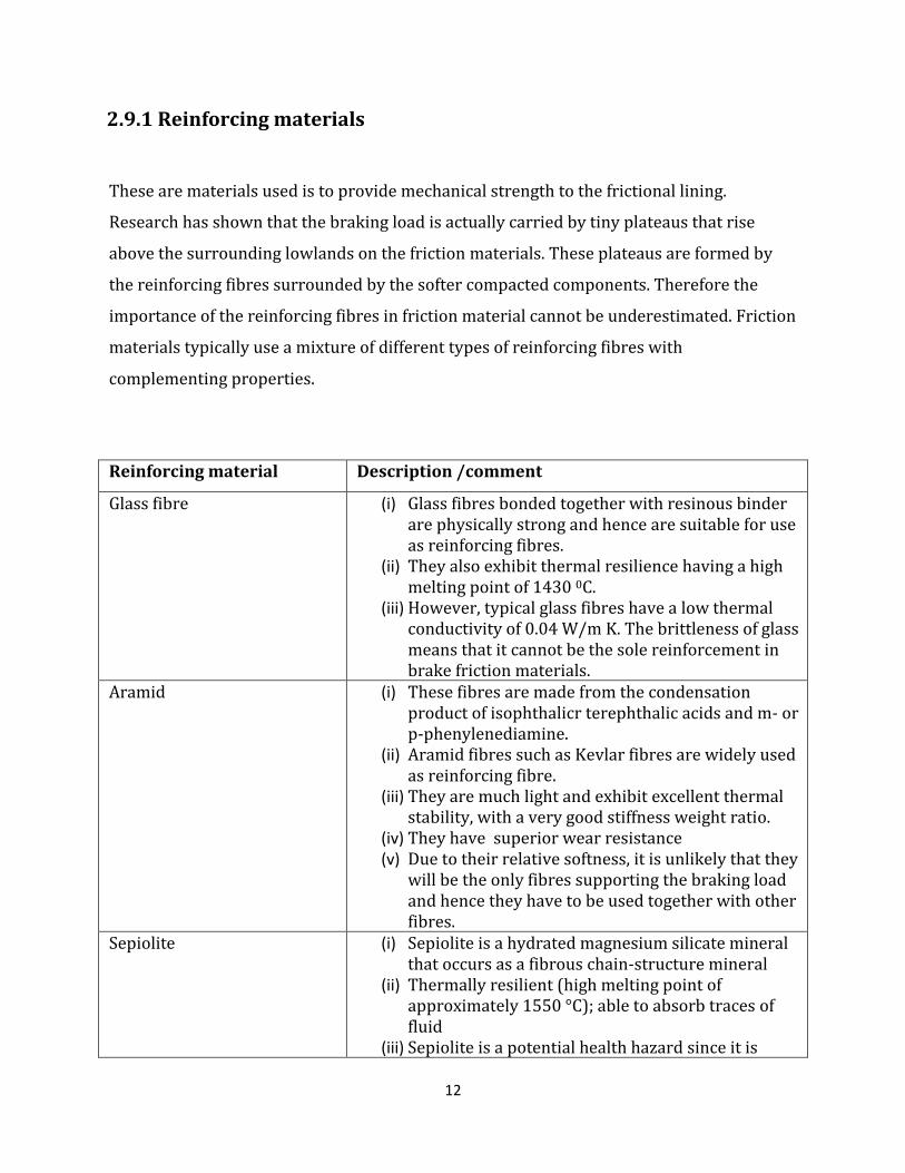
2.9.1 Reinforcing materials
These are materials used is to provide mechanical strength to the frictional lining.
Research has shown that the braking load is actually carried by tiny plateaus that rise
above the surrounding lowlands on the friction materials. These plateaus are formed by
the reinforcing fibres surrounded by the softer compacted components. Therefore the
importance of the reinforcing fibres in friction material cannot be underestimated. Friction
materials typically use a mixture of different types of reinforcing fibres with
complementing properties.
Reinforcing material Description /comment
Glass fibre (i) Glass fibres bonded together with resinous binder are physically strong and hence are suitable for use as reinforcing fibres.
(ii) They also exhibit thermal resilience having a high melting point of 1430 0C.
(iii) However, typical glass fibres have a low thermal conductivity of 0.04 W/m K. The brittleness of glass means that it cannot be the sole reinforcement in brake friction materials.
Aramid (i) These fibres are made from the condensation product of isophthalicr terephthalic acids and m- or p-phenylenediamine.
(ii) Aramid fibres such as Kevlar fibres are widely used as reinforcing fibre.
(iii) They are much light and exhibit excellent thermal stability, with a very good stiffness weight ratio.
(iv) They have superior wear resistance (v) Due to their relative softness, it is unlikely that they
will be the only fibres supporting the braking load and hence they have to be used together with other fibres.
Sepiolite (i) Sepiolite is a hydrated magnesium silicate mineral that occurs as a fibrous chain-structure mineral
(ii) Thermally resilient (high melting point of approximately 1550 °C); able to absorb traces of fluid
(iii) Sepiolite is a potential health hazard since it is

13
associated with the development of inflammation in lung and pulmonary interstitial fibrosis and therefore not a suitable replacements for asbestos.
Potassium titanate (i) They are fibres prepared from highly refined, single
crystals. (ii) They are thermally resilient with a melting point of
approximately 1371 °C (iii) They are very hard and exhibit good wear
resistance (iv) However they are a health hazard since they are
associated with mesothelioma.
Ceramic (i) These are made of metal oxides such a alumina (aluminum oxide) as well as carbides such as silicon carbide
(ii) They have high thermal resistance with melting points ranging from 1850 to 30000 C. They have high strength-weight ratio.
(iii) However, since they are brittle they cannot be used alone.
Metallic (i) Metallic chips or granules are commonly used as reinforcing fibres and hence they are referred to as metallic ‘fibres’. Examples of metallic fibres include steel, brass and copper.
(ii) The advantage of using metal fibres is that they have very high conductivities able to remove heat from the frictional surfaces very quickly.
(iii) However some metallic fibres such as steel will rust, especially if the vehicle has been operating in a corrosive environment, thereby compromising their functionality as reinforcing fibres.
(iv) Addition metallic fibres such as steel might cause excessive wear of the brake disc if they are present in large proportions as well as increase friction coefficient fluctuations.
14
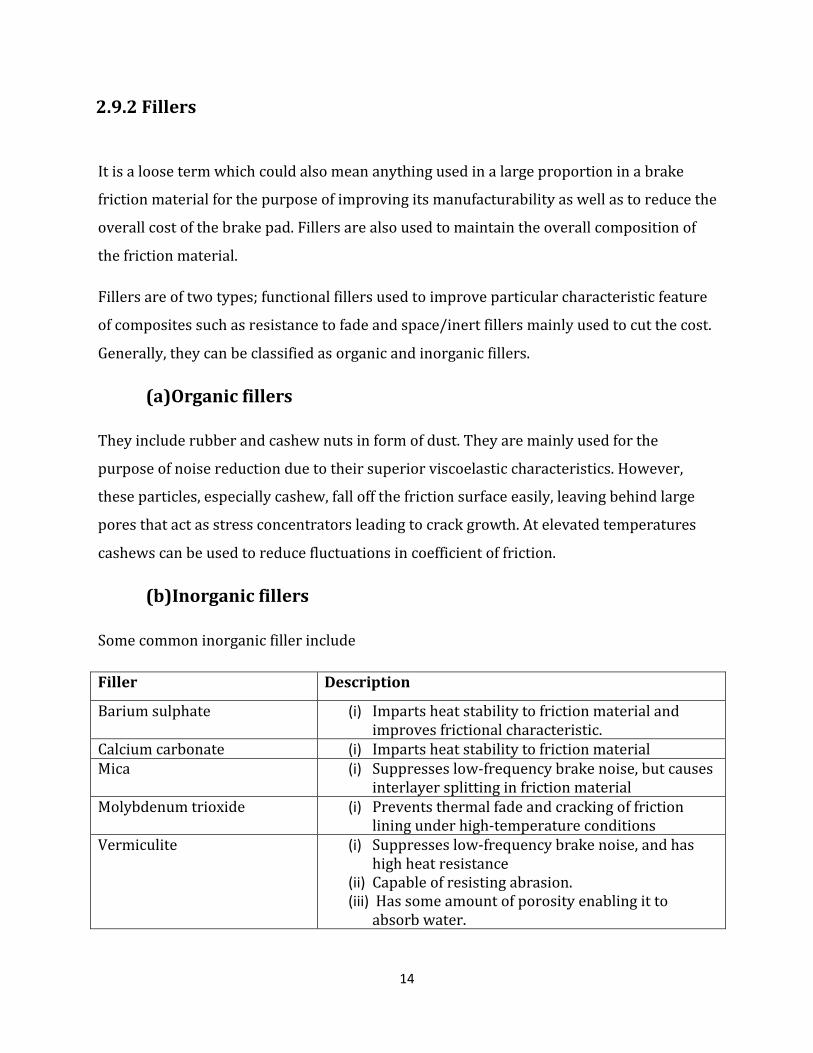
2.9.2 Fillers
It is a loose term which could also mean anything used in a large proportion in a brake
friction material for the purpose of improving its manufacturability as well as to reduce the
overall cost of the brake pad. Fillers are also used to maintain the overall composition of
the friction material.
Fillers are of two types; functional fillers used to improve particular characteristic feature
of composites such as resistance to fade and space/inert fillers mainly used to cut the cost.
Generally, they can be classified as organic and inorganic fillers.
(a)Organic fillers
They include rubber and cashew nuts in form of dust. They are mainly used for the
purpose of noise reduction due to their superior viscoelastic characteristics. However,
these particles, especially cashew, fall off the friction surface easily, leaving behind large
pores that act as stress concentrators leading to crack growth. At elevated temperatures
cashews can be used to reduce fluctuations in coefficient of friction.
(b)Inorganic fillers
Some common inorganic filler include
Filler Description
Barium sulphate (i) Imparts heat stability to friction material and improves frictional characteristic.
Calcium carbonate (i) Imparts heat stability to friction material Mica (i) Suppresses low-frequency brake noise, but causes
interlayer splitting in friction material Molybdenum trioxide (i) Prevents thermal fade and cracking of friction
lining under high-temperature conditions Vermiculite (i) Suppresses low-frequency brake noise, and has
high heat resistance (ii) Capable of resisting abrasion. (iii) Has some amount of porosity enabling it to
absorb water.
15
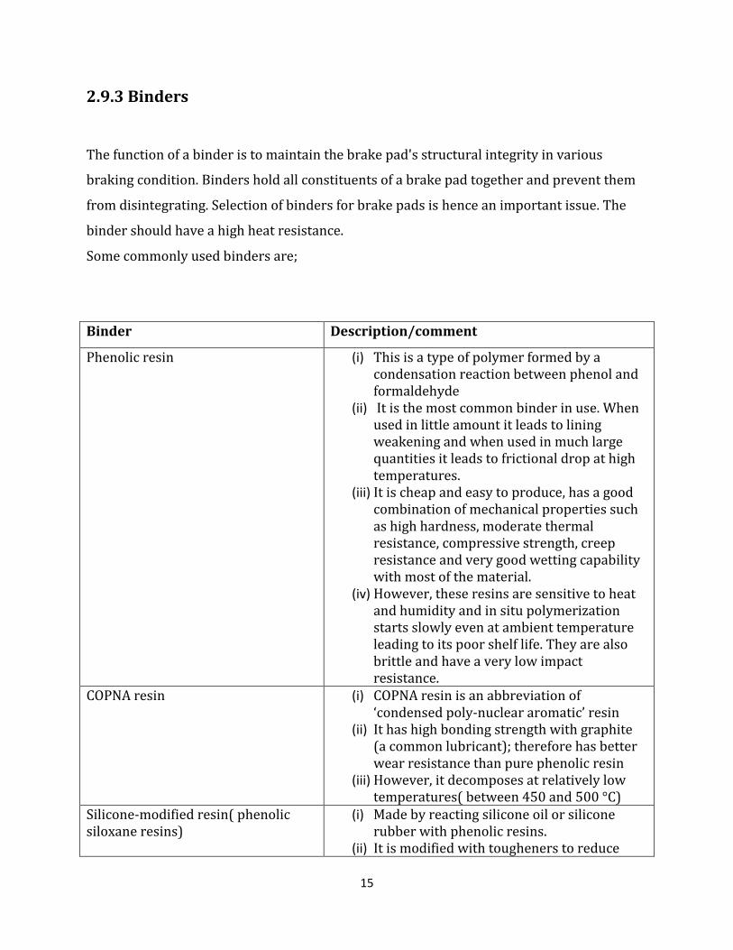
2.9.3 Binders
The function of a binder is to maintain the brake pad's structural integrity in various
braking condition. Binders hold all constituents of a brake pad together and prevent them
from disintegrating. Selection of binders for brake pads is hence an important issue. The
binder should have a high heat resistance.
Some commonly used binders are;
Binder Description/comment
Phenolic resin (i) This is a type of polymer formed by a condensation reaction between phenol and formaldehyde
(ii) It is the most common binder in use. When used in little amount it leads to lining weakening and when used in much large quantities it leads to frictional drop at high temperatures.
(iii) It is cheap and easy to produce, has a good combination of mechanical properties such as high hardness, moderate thermal resistance, compressive strength, creep resistance and very good wetting capability with most of the material.
(iv) However, these resins are sensitive to heat and humidity and in situ polymerization starts slowly even at ambient temperature leading to its poor shelf life. They are also brittle and have a very low impact resistance.
COPNA resin
(i) COPNA resin is an abbreviation of ‘condensed poly-nuclear aromatic’ resin
(ii) It has high bonding strength with graphite (a common lubricant); therefore has better wear resistance than pure phenolic resin
(iii) However, it decomposes at relatively low temperatures( between 450 and 500 °C)
Silicone-modified resin( phenolic siloxane resins)
(i) Made by reacting silicone oil or silicone rubber with phenolic resins.
(ii) It is modified with tougheners to reduce

16
brittleness (iii) However, the original characteristics of
thermal and chemical resistance of phenolic resins would be compromised and the modified resin becomes highly toxic.
(iv) Kane and Mowers succeed in combining phenolic resins with silicone to form phenolic siloxane resins having enhanced impact resistance
Cyanate ester resin (i) They are formed from polyfunctional
cyanate monomers. (ii) They are stable at elevated temperatures,
chemically inert and have damping properties.
(iii) However they are brittle like the phenolic- based resins
Epoxy-modified resin
(i) At temperatures above 2600C, typical epoxy resin binders degrade, to increase the operating temperatures of epoxy resins, special curing agents have to be used.
(ii) Epoxy is used to modify phenolic resins, resulting in the synergistic effect of having a higher heat resistance than phenolic resin or epoxy resin alone and has a high frictional stability.
Thermoplastic polyimide resin (i) This is a product of fluoro resin and calcium carbonate.
(ii) It is abrasion resistant and does not exhibit thermal fade commonly experienced with phenolic - based resins or induce excessive brake disc wear.
(iii) However, its thermal conductivity is approximately three times lower than that of phenolic resins, so it is less able to dissipate heat away from the friction surface.

17
2.9.4 Frictional additives
These are components added to frictional lining to aid in the modification of the friction co-
efficient and wear rates. They can be categorized into two classes: lubricants and abrasives.
According to experiment done by Kim and Jang on brake pads with varying quantity of
lubricants (antimony sulphide) and abrasive (zirconium silicate) it was discovered that
friction coefficient stability largely depended on the quantity of either lubricant or abrasive
and hence an optimum quantity of each must be used. This is because increase in the
quantity of lubricants materials in the lining leads to increase in friction co-efficient
stability while increase in quantity of abrasive materials leads to instability in friction co-
efficient
(a) Lubricants
They are mainly used to stabilize the developed friction coefficients during braking,
especially at high temperatures. Commonly used lubricants include
Lubricant Description /comment
Graphite (i) Graphite is one of the most widely used lubricants. It is available in natural or synthetic forms and as flakes or powder. Graphite in the flake form has better lubrication properties, while graphite in powder form is superior in dissipating heat generated during braking
(ii) It is able to form a lubricant layer on the opposing counter friction material rapidly
(iii) However, graphite cannot be used too liberally in phenolic resins because the bonding strength between graphite and phenolic resin is weak, leading to low shear strengths.
Metal sulphides (i) These have good lubricating properties, and low thermal conductivities when compared to graphite.
(ii) They include antimony, tin, copper and lead sulphides
18
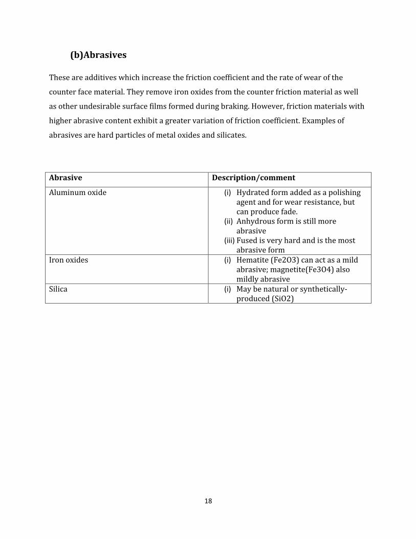
(b)Abrasives
These are additives which increase the friction coefficient and the rate of wear of the
counter face material. They remove iron oxides from the counter friction material as well
as other undesirable surface films formed during braking. However, friction materials with
higher abrasive content exhibit a greater variation of friction coefficient. Examples of
abrasives are hard particles of metal oxides and silicates.
Abrasive Description/comment
Aluminum oxide (i) Hydrated form added as a polishing agent and for wear resistance, but can produce fade.
(ii) Anhydrous form is still more abrasive
(iii) Fused is very hard and is the most abrasive form
Iron oxides (i) Hematite (Fe2O3) can act as a mild abrasive; magnetite(Fe3O4) also mildly abrasive
Silica (i) May be natural or synthetically-produced (SiO2)

19
CHAPTER THREE
FRICTIONAL LINING MATERIALS
3.1 Materials requirement
Desirable Properties for friction linings brakes
(i) The frictional lining as well as the rotor materials should have a high
coefficient of friction.
(ii) The frictional lining material in contact with the rotor should resist
wear effects.
(iii) The value of coefficient of friction should be constant over a range of
temperatures and pressures.
(iv) The materials should be resistant to the environmental effects such as
moisture, dust, pressure.
(v) The materials should possess good thermal properties, high heat
capacity, and good thermal conductivity, withstand high temperature.
(vi) The materials should be able to withstand high contact pressures
which are experienced during braking.
(vii) The materials should have good shear strength which is transferred to
friction forces.
(viii) Should be safe to use and not cause environmental pollution
(ix) The materials should have low specific weight so as to improve on the
fuel economy.
20
3.2 Materials used in the frictional lining formulation
Evidently, it is difficult to find a material which has all the above characteristics and hence a
mixture of different materials is used to obtain characteristics which are close to the
requirement. These different materials used are grouped into different categories. These
categories are: reinforcing materials, binders, frictional additives and fillers.
3.2.1 Reinforcing materials
a) Steel
When steel is used in form of powder, granules or chips it serves as an abrasive. However
when used in form of fibre it serves as a reinforcing material. Steel is used in brake pad
manufacture because of its good thermal conductivity and high strength. Steel can also
withstand high temperatures of above 10000c.
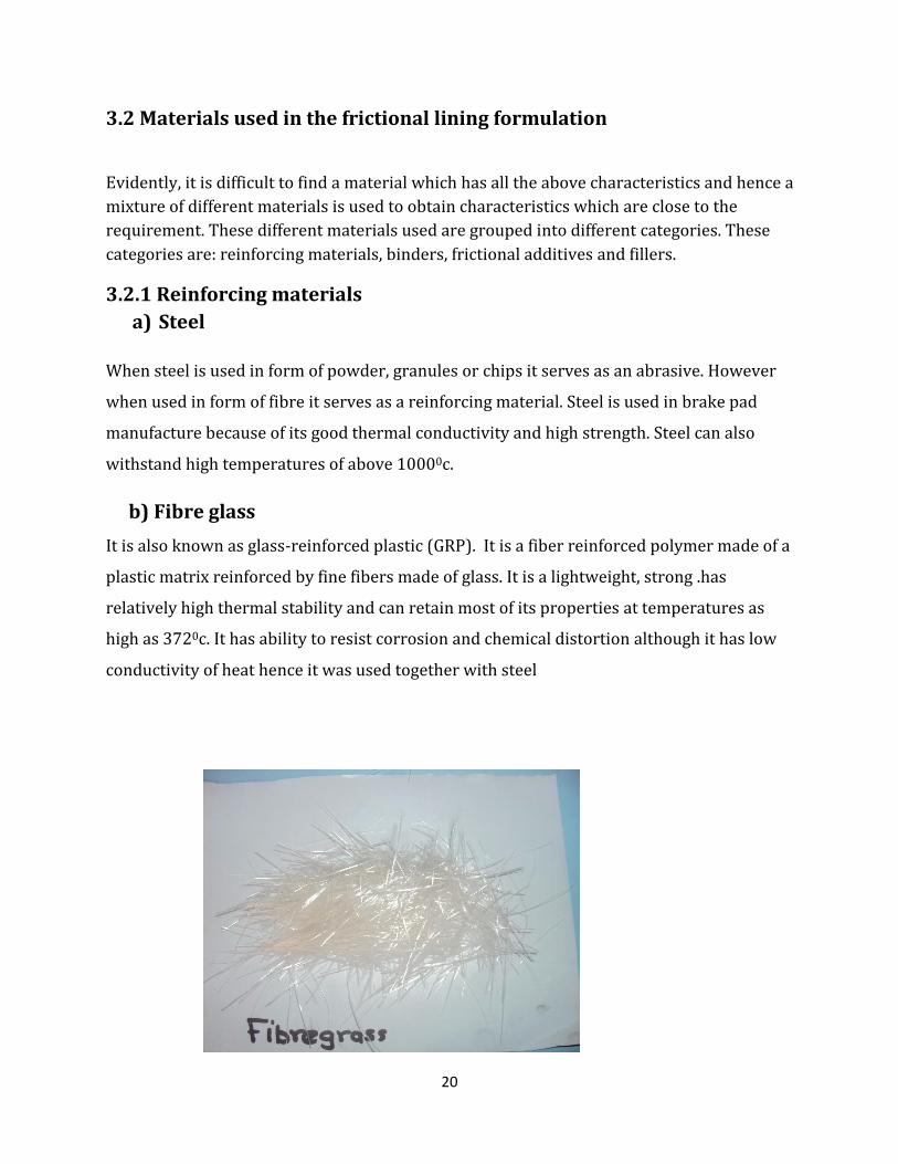
b) Fibre glass
It is also known as glass-reinforced plastic (GRP). It is a fiber reinforced polymer made of a
plastic matrix reinforced by fine fibers made of glass. It is a lightweight, strong .has
relatively high thermal stability and can retain most of its properties at temperatures as
high as 3720c. It has ability to resist corrosion and chemical distortion although it has low
conductivity of heat hence it was used together with steel
21
3.2.2 Fillers
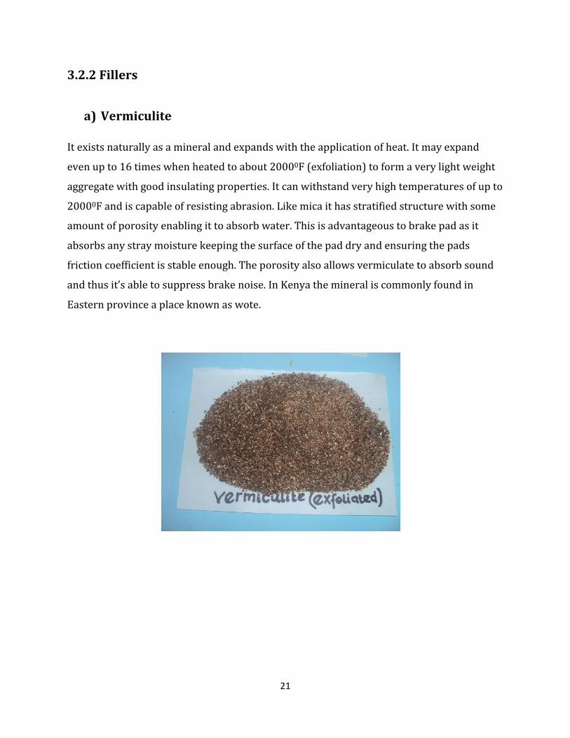
a) Vermiculite
It exists naturally as a mineral and expands with the application of heat. It may expand
even up to 16 times when heated to about 20000F (exfoliation) to form a very light weight
aggregate with good insulating properties. It can withstand very high temperatures of up to
20000F and is capable of resisting abrasion. Like mica it has stratified structure with some
amount of porosity enabling it to absorb water. This is advantageous to brake pad as it
absorbs any stray moisture keeping the surface of the pad dry and ensuring the pads
friction coefficient is stable enough. The porosity also allows vermiculate to absorb sound
and thus it’s able to suppress brake noise. In Kenya the mineral is commonly found in
Eastern province a place known as wote.
22
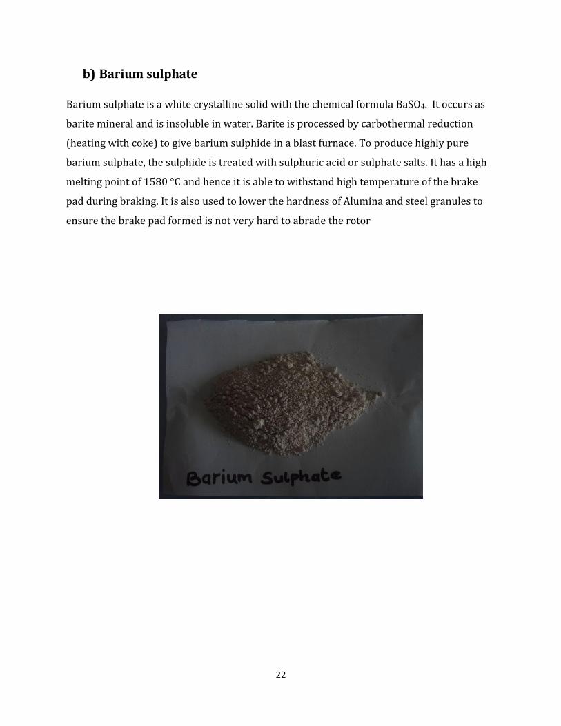
b) Barium sulphate
Barium sulphate is a white crystalline solid with the chemical formula BaSO4. It occurs as
barite mineral and is insoluble in water. Barite is processed by carbothermal reduction
(heating with coke) to give barium sulphide in a blast furnace. To produce highly pure
barium sulphate, the sulphide is treated with sulphuric acid or sulphate salts. It has a high
melting point of 1580 °C and hence it is able to withstand high temperature of the brake
pad during braking. It is also used to lower the hardness of Alumina and steel granules to
ensure the brake pad formed is not very hard to abrade the rotor
23
3.2.3 Frictional additives
a) Abrasives
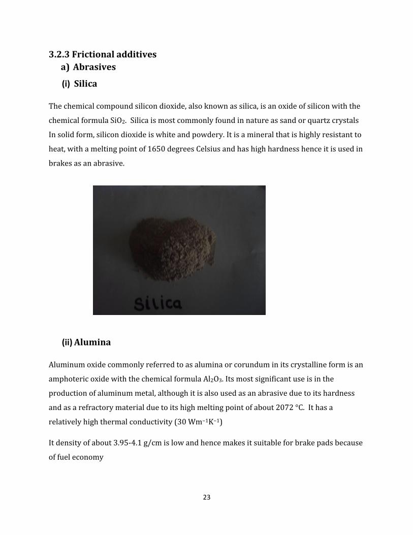
(i) Silica
The chemical compound silicon dioxide, also known as silica, is an oxide of silicon with the
chemical formula SiO2. Silica is most commonly found in nature as sand or quartz crystals
In solid form, silicon dioxide is white and powdery. It is a mineral that is highly resistant to
heat, with a melting point of 1650 degrees Celsius and has high hardness hence it is used in
brakes as an abrasive.
(ii) Alumina
Aluminum oxide commonly referred to as alumina or corundum in its crystalline form is an
amphoteric oxide with the chemical formula Al2O3. Its most significant use is in the
production of aluminum metal, although it is also used as an abrasive due to its hardness
and as a refractory material due to its high melting point of about 2072 °C. It has a
relatively high thermal conductivity (30 Wm−1K−1)
It density of about 3.95-4.1 g/cm is low and hence makes it suitable for brake pads because
of fuel economy
24
b) Lubricants
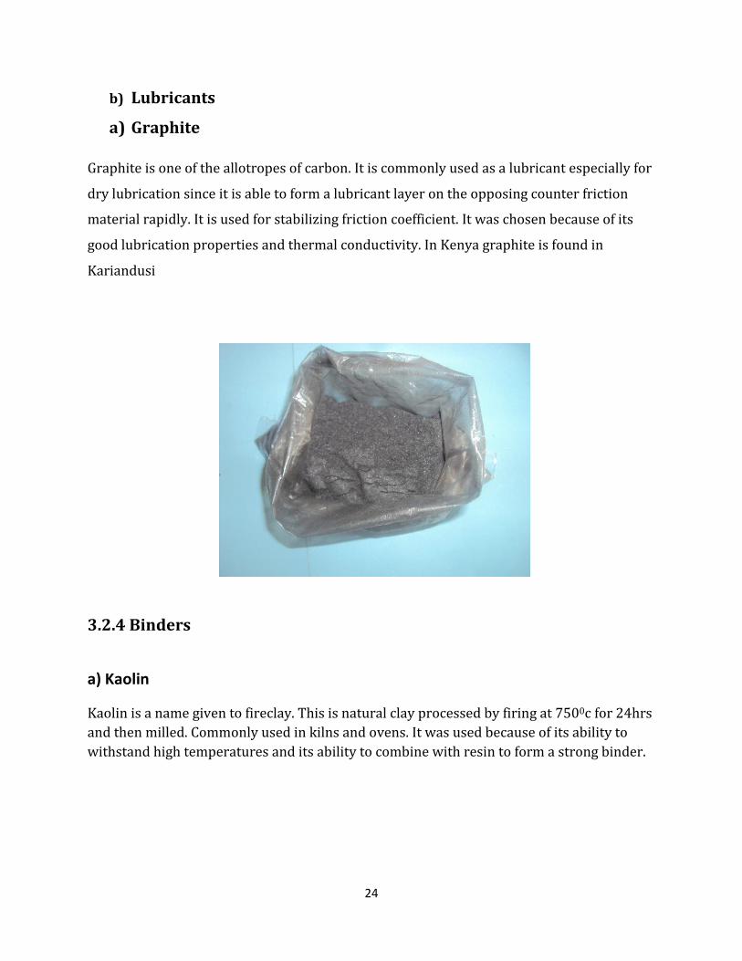
a) Graphite
Graphite is one of the allotropes of carbon. It is commonly used as a lubricant especially for
dry lubrication since it is able to form a lubricant layer on the opposing counter friction
material rapidly. It is used for stabilizing friction coefficient. It was chosen because of its
good lubrication properties and thermal conductivity. In Kenya graphite is found in
Kariandusi
3.2.4 Binders
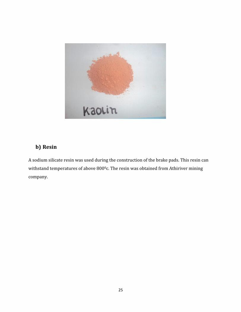
a) Kaolin
Kaolin is a name given to fireclay. This is natural clay processed by firing at 7500c for 24hrs
and then milled. Commonly used in kilns and ovens. It was used because of its ability to
withstand high temperatures and its ability to combine with resin to form a strong binder.
25
b) Resin
A sodium silicate resin was used during the construction of the brake pads. This resin can
withstand temperatures of above 8000c. The resin was obtained from Athiriver mining
company.

26
3.3 Choice of sample composition
Sample 1
Material Weight composition Percentage composition
Binder Resin
24g 13.9
Kaolin
10g 5.8
Filler Vermiculite
45.4g 26.4
Barium sulphate
27.3g 15.9
Reinforcing Steel
8g 4.7
Fibre glass 10g 5.8 Abrasive Silica
15.1g 8.8
Alumina 22.7g 13.2 Lubricant Graphite
9.5g 5.5
13.90%5.80%
26.40%
13.20%
5.80%
15.90%
8.80%
5.50% 4.70%
Percentage composition of sample 1
Resin
Kaolin
Vermiculite
Alumina
Fibre glass
Barium sulphate
Silica
Graphite
Steel

27
Sample 2
Material Weight composition Percentage
composition
Binder Resin 31g 15.7
Kaolin 20g 10.1
Filler Vermiculite 45.4g 23.0
Barium sulphate 27.3g 13.8
Reinforcing Steel 11g 5.6
Fibre glass 15g 7.6
Abrasive Silica 15.4g 7.8
Alumina 22.7g 11.5
Lubricant Graphite 9.5g 4.8
19.70%
42.30%
10.50%
22.00%
5.50%
Percentage composition of material categories. sample 1
Binder
Filler
Reinforcing
Abrasive
Lubricant

28
15.70%
10.10%
4.80%11.50%
23.00%
13.80%
7.80%
5.60%7.60%
Percentage composition of sample 2
Resin
Kaolin
Graphite
Alumina
Vermiculite
Barium sulphate
Silica
Steel
Fibre glass
25.80%
36.80%
13.20%
19.30%
4.80%
Percentage composition of material categories. sample 2
Binder
Filler
Reinforcing
Abrasive
Lubricant
29
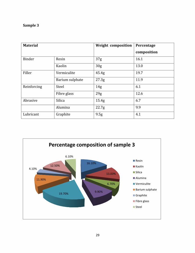
Sample 3
Material Weight composition Percentage
composition
Binder Resin 37g 16.1
Kaolin 30g 13.0
Filler Vermiculite 45.4g 19.7
Barium sulphate 27.3g 11.9
Reinforcing Steel 14g 6.1
Fibre glass 29g 12.6
Abrasive Silica 15.4g 6.7
Alumina 22.7g 9.9
Lubricant Graphite 9.5g 4.1
16.10%
13.00%
6.70%
9.90%19.70%
11.90%
4.10%12.50%
6.10%
Percentage composition of sample 3
Resin
Kaolin
Silica
Alumina
Vermiculite
Barium sulphate
Graphite
Fibre glass
Steel
30
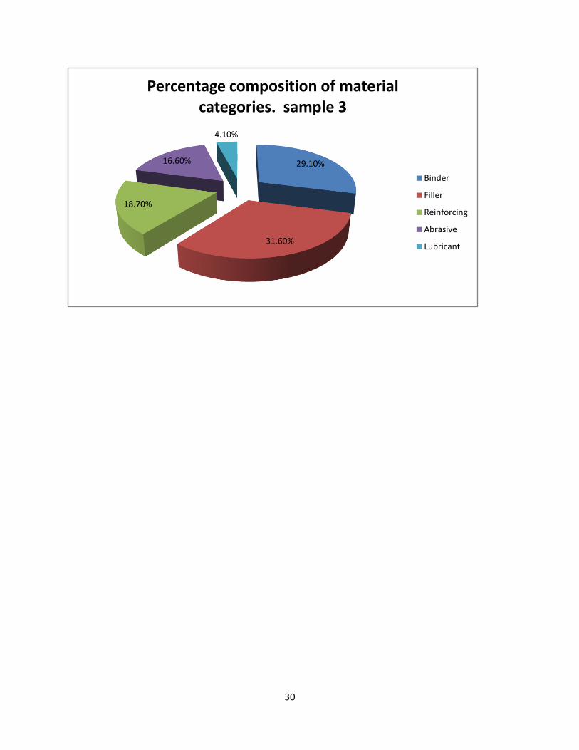
29.10%
31.60%
18.70%
16.60%
4.10%
Percentage composition of material categories. sample 3
Binder
Filler
Reinforcing
Abrasive
Lubricant

31
CHAPTER FOUR
MANUFACTURING PROCESS
4.1 Materials preparation
The brake pads needed different materials for its construction as listed above. They were
obtained from different locations and also existed in different forms. Hence they needed
preparations to transform them into a state that was more appropriate for the brake pads
construction.
The materials were first collected into a central point before preparation. The preparation
process involved
(i) Crushing in a crushing machine to obtain fine powder. These materials included;
Alumina, barium sulphate, kaolin and silica.
(ii) Vermiculite obtained in natural form was expanded by a process of exfoliation
which involved heating it to temperatures of about 2000F.
(iii) Steel was obtained from the steel wool manufacturers in form of fibre and was
chopped into small lengths of approximately 5mm.
(iv) The above process for steel was also done for fiberglass
Using predetermined weights, the materials were weighed on a weighing balance for every
sample formulation that is samples 1, 2, and 3.

32
4.2 Mould
A mould made of sheet metal to be used in the moulding process was fabricated. This was
made in a shape identical to that of a brake pad already existing in the market.
It was made by folding a sheet metal of height 3mm to the required shape and the joint was
arc welded. For testing purpose a 30mm by40mm by 40mm mould was also fabricated. The
moulds prepared are shown below.
A photo of the two moulds fabricated
33
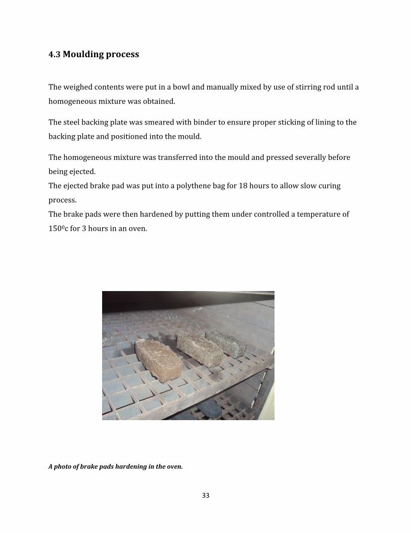
4.3 Moulding process
The weighed contents were put in a bowl and manually mixed by use of stirring rod until a
homogeneous mixture was obtained.
The steel backing plate was smeared with binder to ensure proper sticking of lining to the
backing plate and positioned into the mould.
The homogeneous mixture was transferred into the mould and pressed severally before
being ejected.
The ejected brake pad was put into a polythene bag for 18 hours to allow slow curing
process.
The brake pads were then hardened by putting them under controlled a temperature of
1500c for 3 hours in an oven.
A photo of brake pads hardening in the oven.

34
The testing samples were also prepared in a similar way and are shown below
Each of the samples was cut to produce three testing specimens of dimensions 20mm
by20mm by10mm for testing internal shear strength.
4.4 Finishing process
After the moulding process finishing operations were done on the brake pads. These
processes included;
The heat groove was cut by use of a grinding machine. The cut was done to a depth of about
3mm on the lining.
The surfaces of the constructed brake pads were also leveled to acquire a uniform
thickness as well as a uniform surface finish. This was done by the use of a grinding
machine to eat away excess materials.

35
The brake pad was finally painted to look presentable. The resulting pads are shown below.
A photo of the resulting brake pads

36
CHAPTER FIVE
LAB TESTING
5.1 Hardness testing
After the brake pads were constructed a hardness test was to be conducted. The hardness
test used was Rockwell hardness test. This was preferred because; it can be used for non
metals, indenters are small hence it could not destroy the specimen, it is a high speed test
and the surface does not have to be reflective
This test consists of an indenter which is a diamond cone with an angle of 1200 and a tip
radius of 0.2mm or steel balls of various diameters. The Kenya standard for this test is KS
06-71:1980. Main scale available are Rockwell C which uses a diamond cone indenter and a
load of 150 kg, Rockwell B where the indenter is 1/16 inch steel ball of 100kg and
Rockwell A which has same indenter as Rockwell C among others. In this case Rockwell C
was used.
The test was done on different positions of the brake pad and an average reading recorded.
SAMPLE TEST RESULTS (Rockwell hardness values)
Test 1 Test 2 Test 3 Average
1 84 88 86 86
2 79 83 81 81
3 77 81 76 78

37
74
76
78
80
82
84
86
88
19.7 25.5 29.1
Har
dn
ess
val
ue
Percentage binder
Graph of Hardness value against binder
74
76
78
80
82
84
86
88
10.5 13.2 18.7
Har
dn
ess
val
ue
Percentage reinforcing fibre
Graph of hardness against reinforcing fibre

38
5.2 Shear strength
This is one of the most important tests in a brake pad. It tests the strength of a brake pad
under shear force hence helps to determine whether the formulation is strong enough to
withstand the forces experienced during braking operation.
The test consists of a special test rig which is used to apply shear load as a normal tension
load. A specimen of dimensions 20mmby 20mm by10mm is loaded on the test rig leaving
it with no room for play. The rig is then mounted on a tensile testing machine and tensile
load is applied until the specimen fails by developing a crack.
The maximum load to failure is determined from the difference between initial and final
loading. The value of ultimate tensile strength is determined as follows:
A photo the testing rig used

39
Results obtained
Sample Test Maximum load
(Newton)
1 1 349.2
2 332.1
3 352.8
Average 344.7
2 1 386.3
2 364.7
3 377.9
Average 376.3
3 1 371.5
2 392.4
3 379.7
Average 381.2
Analysis
Ultimate tensile strength (UTS) = Average maximum load to crack formation
shear area
Shear area = length х width
= 20mm х 10mm= 200mm2
Sample calculations
For sample 1
UTS = 344.7N
200mm = 1.7235N/mm2
40
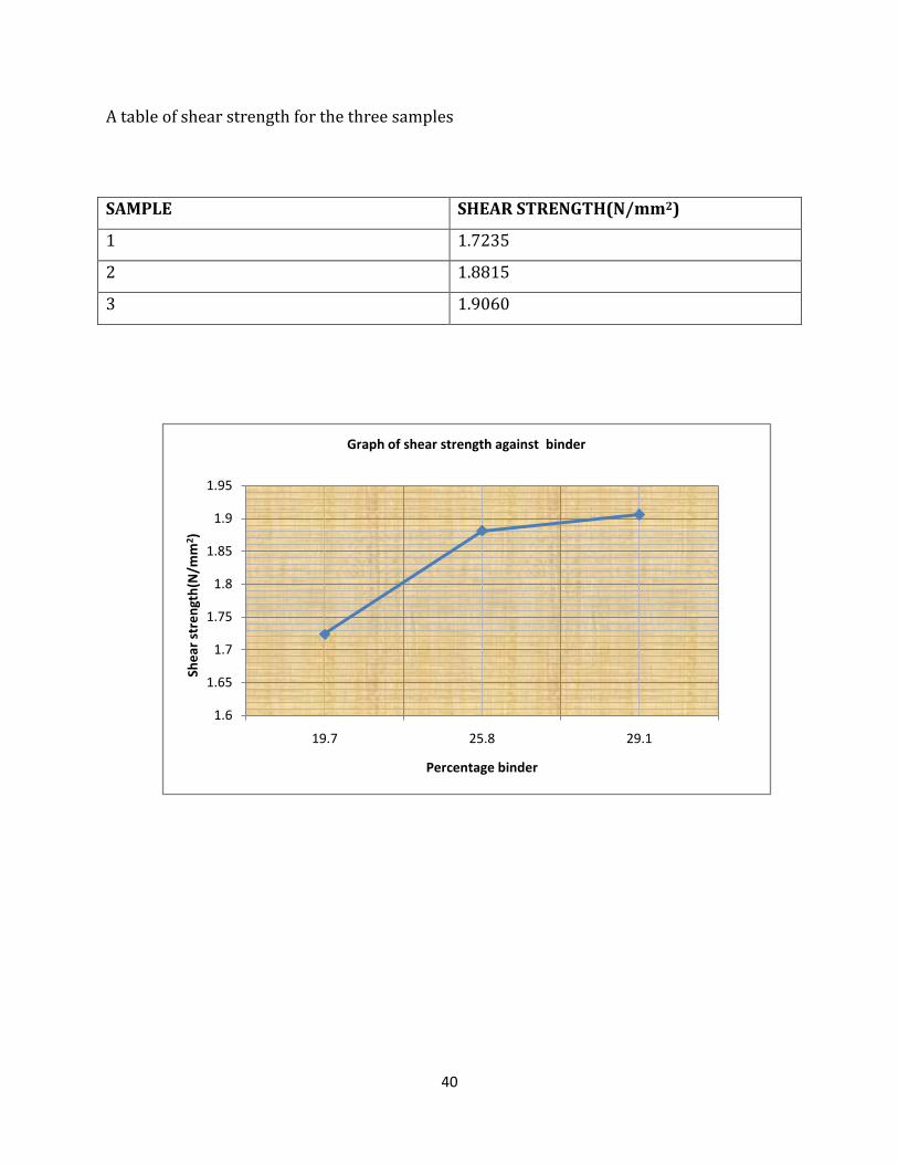
A table of shear strength for the three samples
SAMPLE SHEAR STRENGTH(N/mm2)
1 1.7235
2 1.8815
3 1.9060
1.6
1.65
1.7
1.75
1.8
1.85
1.9
1.95
19.7 25.8 29.1
She
ar s
tre
ngt
h(N
/mm
2 )
Percentage binder
Graph of shear strength against binder
41
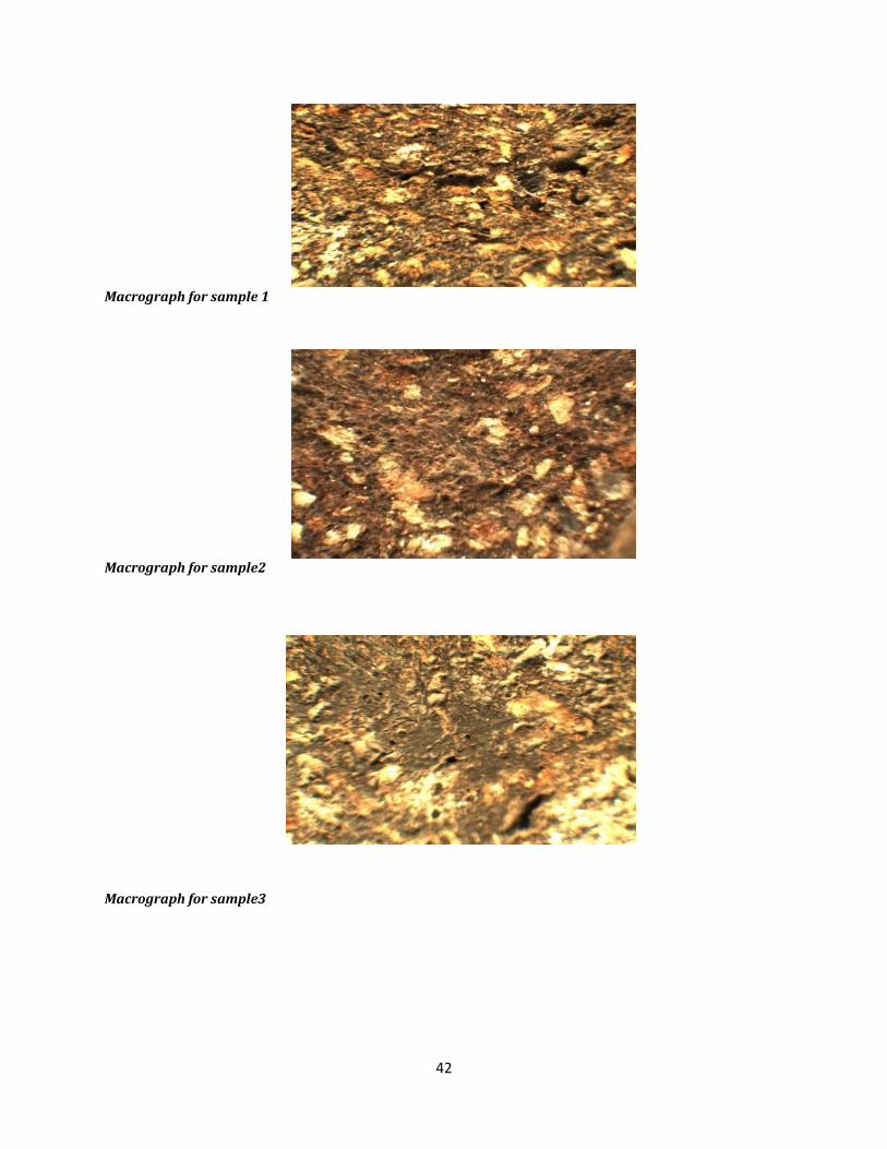
5.3 Macrostructure study
In this test an Optika vision microscope was used. The microscope has an inbuilt digital
camera connected to a computer via a USB cable which enables images of specimen to be
seen on a computer screen. The images seen on the computer were studied.
The specimens were first ground to obtain a flat surface. After placing the specimen in the
microscopes field of view, the lenses were adjusted until a sharp image was obtained.
The image was then transferred to a computer for study. The process was repeated for the
samples 2 and 3.
The results obtained are shown in the next page.
1.6
1.65
1.7
1.75
1.8
1.85
1.9
1.95
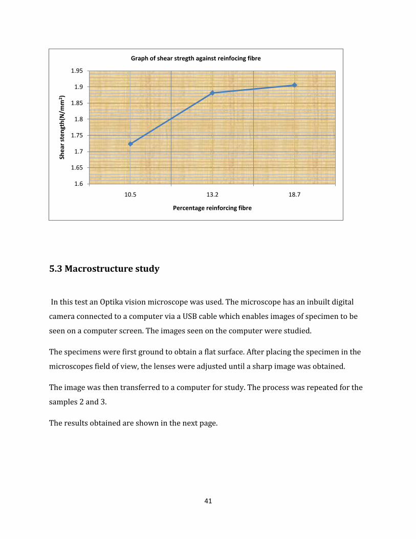
10.5 13.2 18.7
She
ar s
ten
gth
(N/m
m2 )
Percentage reinforcing fibre
Graph of shear stregth against reinfocing fibre
42
Macrograph for sample 1
Macrograph for sample2
Macrograph for sample3
43
CHAPTER SIX
DISCUSSION, CONCLUSION AND RECOMMENDATION
6.1 Discussion
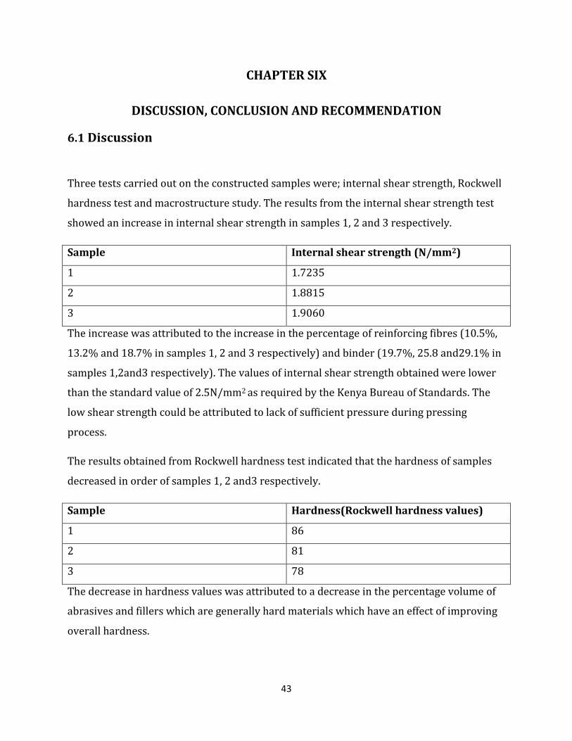
Three tests carried out on the constructed samples were; internal shear strength, Rockwell
hardness test and macrostructure study. The results from the internal shear strength test
showed an increase in internal shear strength in samples 1, 2 and 3 respectively.
Sample Internal shear strength (N/mm2)
1 1.7235
2 1.8815
3 1.9060
The increase was attributed to the increase in the percentage of reinforcing fibres (10.5%,
13.2% and 18.7% in samples 1, 2 and 3 respectively) and binder (19.7%, 25.8 and29.1% in
samples 1,2and3 respectively). The values of internal shear strength obtained were lower
than the standard value of 2.5N/mm2 as required by the Kenya Bureau of Standards. The
low shear strength could be attributed to lack of sufficient pressure during pressing
process.
The results obtained from Rockwell hardness test indicated that the hardness of samples
decreased in order of samples 1, 2 and3 respectively.
Sample Hardness(Rockwell hardness values)
1 86
2 81
3 78
The decrease in hardness values was attributed to a decrease in the percentage volume of
abrasives and fillers which are generally hard materials which have an effect of improving
overall hardness.

44
The values obtained from the hardness test for sample 1 and 2 were within to the
minimum range of between 80-85 as required by the Kenya Bureau of Standards while
that of sample 3 was below.
The results from the macrostructure showed that the four subcomponents were not
uniformly distributed as required. Pores were also observed on the samples which gave an
indication that pressure was not sufficient.
Several challenges were faced during the period this project was conducted. These
included;
(i) Lack of facilities such as mixing and moulding machine for use in construction
(ii) Lack of facilities for testing other parameters such as friction coefficient and wear
rate which are also important.
(iii) Lack of co-operation from manufacturers who were not ready to give important
information as wells as allow the use of their facilities.
6.2 Conclusion
We were able to design heat resistant brake pads of materials free of asbestos with
improved internal shear strength. The materials used in the design were locally available.
The locally available materials were used to construct formulations for three samples 1, 2
and 3 which were then tested for shear strength, hardness and macrostructure study.
Since the materials were free of asbestos they can be used as brake pad manufacturing
materials. This indicates that materials used for manufacture of brake linings can be
obtained locally instead of importing.
45
6.3 Recommendations
More research could still be done to achieve optimum brake pads from locally available
materials. Some of the recommendations are;
(i) Materials should be processed to a fine finish before use as opposed to their use in
natural form which would help in improving the final quality of the brake pads
(ii) Machines should be designed for use in the manufacture of brake pads using the
formulations.
46
REFERENCES
(i)Carlson, R. A. and Headley, J. L. Fiber mixtures for brake pads, US Pat. 5871159,
1999 United States Patent and Trademark Office.
(ii) Institution of Mechanical engineers journal vol. 218 part D: J Automobiles
Engineering, Chan and G.W. Stochowiak, Review of automobile brake fiction
materials.
(iii) H. Jang, et al. “The effect of metal fibres on the friction performance of automotive
brake friction materials” Wear, Vol.88
(iv) J. Bijwe, composites as friction material: recent development in non-asbestos fiber
reinforced friction material- a review, polym.comp.18 (3) (1997)378-396
(v)P. J. Blau. Compositions, Function and testing of Brake Materials and their Additives,
RNL/TM-2001/64.September 2001.
(vi)G.O Rading. Concise notes on materials science and engineering, 2006
(vii)Kenya standards for brake pads and brake linings from Kenya Bureau of
standards
(viii) Patent applications by Dickinson Wright Pllc.

47

48

49