UnidriveC Free Standing Fully Engineered Cabinet Drives...
9
62 www.emersonct.com 800-893-2321 Unidrive SP Free Standing Unidrive C Free Standing Fully Engineered Cabinet Drives 150 hp to 1000 hp Unidrive SP Free Standing is a range of compact AC drives for high power motors. They inherit their reliability, performance and flexibility from the Unidrive SP modular range. Unidrive SP Free Standing drives are fully engineered and tested drive cabinets. The whole enclosure is certified to comply with international standards such as CE and UL. Proven design and international approvals release your engineering resources to focus on your application. A simple model number specifies the drive power, voltage and dynamic braking requirement. Standard cabinet color and dimensions mean that Free Standing drives can be connected together with other manufacturer’s cabinets. Compact size and innovative design enables the drive modules to be easily accessed and removed for servicing or replacement. Standard modules ensure ready availability of components. We understand your needs. Control Techniques has 54 drive centers located in 31 countries to ensure that service, support and expertise are just around the corner, all around the world. A P P R O V A L I S O 9 0 0 1 : 2 0 0 0 Incomer or System Shell Unidrive SP Size 6-8 Unidrive SP Size 9
Transcript of UnidriveC Free Standing Fully Engineered Cabinet Drives...

62
www.emersonct.com
800-893-2321
Unidrive SP
Free Standing
Unidrive C
Free Standing Fully Engineered Cabinet Drives 150 hp to 1000 hp
Unidrive SP Free Standing is a range of compact AC drives for high power motors. They inherit their reliability, performance and flexibility from the Unidrive SP modular range.
Unidrive SP Free Standing drives are fully engineeredand tested drive cabinets. The whole enclosure is certified to comply with international standards such as CE and UL. Proven design and international approvalsrelease your engineering resources to focus onyour application.
A simple model number specifies the drive power, voltage and dynamic braking requirement. Standard cabinet color and dimensions mean that Free Standing drives can be connected together with othermanufacturer’s cabinets.
Compact size and innovative design enables the drive modules to be easily accessed and removed for servicing or replacement. Standard modules ensure ready availability of components.
We understand your needs. Control Techniques has 54drive centers located in 31 countries to ensure that service, support and expertise are just around thecorner, all around the world.
APPROVAL
ISO
9
001: 2000
Incomer or System Shell
Unidrive SP Size 6-8
Unidrive SP Size 9
63
www.emersonct.com
800-893-2321
Uni
driv
e SP
Fr
ee S
tand
ing
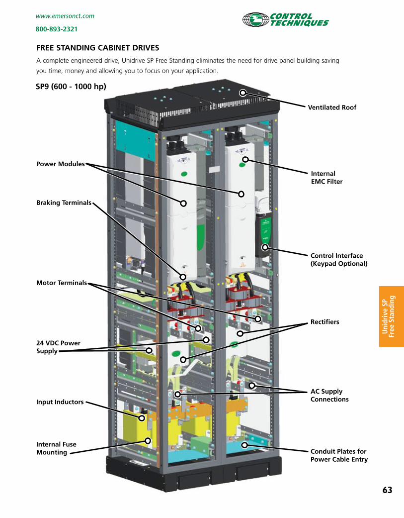
power modules
braking terminals
motor terminals
24 VDc powersupply
input inductors
internal Fusemounting
Ventilated roof
internal emc Filter
control interface(keypad Optional)
rectifiers
ac supplyconnections
conduit plates forpower cable entry
Free stanDinG cabinet DriVes
A complete engineered drive, Unidrive SP Free Standing eliminates the need for drive panel building saving
you time, money and allowing you to focus on your application.
sp9 (600 - 1000 hp)

64
www.emersonct.com
800-893-2321
Unidrive SP
Free Standing
internal emc Filter
sp6, sp7 & sp8 (150 - 500 hp)
Ventilated roof
power module
24 VDc powersupply
motor terminals
Optional braking terminals
internal Fusemounting
conduit plates forpower cable entry
control interface(keypad Optional)
input inductors
much mOre cOmpact
500 hp = 15.8 inches wide
1000 hp = 31.5 inches wide
Unidrive SP Free Standing drives are up to 50% smaller
and are much lighter than other “compact” drive
cabinets. As an example, a 500 hp drive including an
Incomer enclosure is only 31.5” wide. This makes
Unidrive SP Free Standing the obvious choice where
space is a problem such as for new or retrofit energy
saving applications.
prOVen reliabilityUnidrive SP Free Standing utilizes mass produced
modules with proven design and reliability. The modules
and cabinets are assembled using a sequential build
process that eliminates build variation and provides
consistently high quality. Excellent thermal and electrical
design and computer modelling has ensured the
inverters have a long and productive life with trouble
free operation.
a traDitiOn OF perFOrmance sOlutiOnsControl Techniques has a tradition of high performance
solutions. Unidrive SP Free Standing continues that
tradition, able to control virtually any type of AC motor
including synchronous machines.

65
www.emersonct.com
800-893-2321
Uni
driv
e SP
Fr
ee S
tand
ing
Free stanDinG - incOmer
Empty 15.8 inch wide Incomer cabinets are available to
allow you to install your own power input scheme.
For users designing incomers for SP8 and SP9 drives the
cabinets are available with interconnection busbars. For
users designing incomers for SP6 and SP7 drives a
cabinet is available without interconnection busbars as
cables are used to make the connection.
For users who wish to use their own cabinet to create
an incomer for SP8 and SP9 drives, interconnection
busbars may be ordered as an accessory.
pOwer Quality
Supply harmonics may be minimized by using 12 pulse
input versions of SP8 and SP9 Free Standing Drives. The
12 pulse input option is simply specified as part of the
drive order code.
For 12 pulse drives the power connections are made
within a separate incomer cabinet (SP-Incomer Shell 40-
P12-EXX) or your own cabinet using the six phase
interconnection busbar (SP P12 kit).
Engineered solutions that further reduce supply
harmonics using passive in-line filters, active input
modules or 18 pulse configurations are available.
These enable your applications to comply with the
harmonics standards IEEE 519-1992, IEC 61000-2-2,
IEC 61000-2-12 and G5/4-1.
Dynamic brakinG
Unidrive SP Free Standing is also available with
integrated dynamic braking control allowing precision
deceleration profiles to be achieved. This option is
specified as part of the drive order code.
Free stanDinG DriVe speciFicatiOns
Environmental Safety and Electrical Conformance• Humidity 95% maximum (non condensing) at 40°C• Altitude: 0 to 3000 m, derate 1% per 100 m between
1000 m and 3000 m• Vibration: Drive Modules tested in accordance with IEC
60068-2-34• Mechanical Shock Tested: Drive Modules in accordance
with IEC 60068-2-27• Storage temperature -40°C to 50°C• Electromagnetic Immunity complies with EN 61800-3
and EN 61000-6-2• With on board EMC filter, complies with EN 61800-3
(2nd environment)• EN61000-6-4 with optional EMC filter• IEC 60146-1-1 General requirements• IEC 61800-5-1 Safety of Power Drive Systems• IEC 61131-2 I/O• EN 60529 Ingress protection• Safe Torque Off meets EN 954-1-cat3• UL508C (to 600V)• CSA C22.2 no 14-05• IP21 cabinet design, optional IP23
Pictured: SP9 with user designed incomer (interconnection made with SP P06 busbar kit)
Order code Description
sp-incomer-shell-40 empty cabinet with 6 pulse interconnection busbar
sp-incomer-shell-40-p12 empty cabinet with 12 pulseinterconnection busbar
sp-system-shell-40 empty cabinet

www.emersonct.com
800-893-2321
Unidrive SP
66
Free stanDinG ratinGs
Order String sp x x x x -xxx -xxx
Unidrive Product LineSP - Solution PlatformComplete AC in, AC out drive
Enclosure Rating(including incomer if specified) IP21 (Default)-E23 - IP23
Power Range6-9 - Free Standing
Current Rating Step
Voltage Range4 - 380V to 480V6 - 575V to 690V
Dynamic Braking Control 1 - SPFS with dynamic brake control3 - SPFS with no dynamic brake control
Keypad-NKP No KeyPad-LCD -LED
Output module selection
normal Duty heavy Duty Compact Dimensions (inches)DriveOrderCode
Max Cont. Current
(A)
Typical MotorOutput
Max Cont. Current
(A)
Typical MotorOutput
Drive only With incomer cabinet
460V (HP) 460V (HP) H x W x D H x W x D
380-
480
Va
c +
/-10
-%
SP64x1 205 150 180 150
85.8 x 15.8 x 23.6
85.8 x 15.8 x 23.6SP64x2 236 200 210 150SP74x1 290 250 238 200
SP74x2 [9] 350 300 290 250
85.8 x 31.5 x 23.6SP84x1 389 300 335 280
SP84x2 450 400 389 300SP84x3 545 450 450 400SP84x4 620 500 545 450SP94x1 690 600 620 500
85.8 x 31.5 x 23.6 85.8 x 47.3 x 23.6SP94x3 900 800 790 700
SP94x4 1010 900 900 800
SP94x5 1164 1000 1010 900575V (HP) 575V (HP)
SP66x1 125 125 100 100
85.8 x 15.8 x 23.6 85.8 x 31.5 x 23.6
SP66x2 144 150 125 125SP76x1 168 150 144 150SP76x2 192 200 168 150
575-
690
Va
c +
/-10
-%
SP86x1 231 250 186 200SP86x2 266 300 231 250SP86x3 311 350 266 300SP86x4 355 400 311 350SP96x1 400 500 347 400
85.8 x 31.5 x 23.6 85.8 x 47.3 x 23.6SP96x3 533 600 466 500SP96x4 616 700 533 600SP96x5 711 800 622 700
Note: Select model based on actual motor full load current
Normal DutySuitable for most applications, current overload of 110% for 165 seconds is available. Where motor rated current is less than the drive rated continuous current, higher overloads are achieved.
Heavy DutySuitable for demanding applications, current overload of 150% for 60 seconds is available in closed loop and 129% for 97 seconds in open loop.

67
www.emersonct.com
800-893-2321
Uni
driv
e SP
Fr
ee S
tand
ing
Order Code Description
SM-Keypad LED display for configuration and monitoring
SM-Keypad-Plus Enhanced multi-language LCD display
SP-Income-Shell-40 Empty Cabinet (15.8” wide) with 6 Pulse Interconnection Busbar
SP-Incomer-Shell-40-E23 Empty Cabinet (15.8” wide, IP23 Rated) with 6 Pulse Interconnection Busbar
SP-Incomer-Shell-40-P12 Empty Cabinet (15.8” wide) with 12 Pulse Interconnection Busbar.
SP-Incomer-Shell-40-P12-E23 Empty Cabinet (15.8” wide, IP23 Rated) with 12 Pulse Interconnection Busbar
SP-System-Shell-40 Empty Cabinet (15.8” wide)
SP-System-Shell-40-E23 Empty Cabinet (15.8” wide) - IP23 Rated
SP-P06 Kit [1] 6 Pulse Interconnection Busbar for SP8 and SP9
SP-P12 Kit [2] 12 Pulse Interconnection Busbar for SP8 and SP9
6711-0001-00 Mounting Rail (1 Off) - Enables user to mount their own incomer equipment
6541-0047-00 LHS Mounting Bracket - To attach equipment to the mounting rail on left side - Order one for each mounting rail ordered
6541-0048-00 RHS Mounting Bracket - To attach equipment to the mounting rail on right side - Order one for each mounting rail ordered
Kit includes SP System Shell 40 with circuit breaker and operator handle (through front) installed.
Drive Order Code
SP64x1 CB-KIT-SP6411SP64x2 CB-KIT-SP6412SP74x1 CB-KIT-SP7411SP74x2 CB-KIT-SP7412SP84x1 CB-KIT-SP8411SP84x2 CB-KIT-SP8412SP84x3 CB-KIT-SP8413SP84x4 CB-KIT-SP8414SP94x1 CB-KIT-SP9411SP94x3 CB-KIT-SP9413SP94x4 CB-KIT-SP9414SP94x5 CB-KIT-SP9415
separate Free stanDinG accessOries
circuit breaker kits
Internal AC Fuse Selection (Semi Conductor IEC class aR)
Drive Amps Order Code
SP6 & SP7 400 4300-0400
SP8 & SP9 800 4300-0800
spare Fuse OrDer cODes
Foot notes:
[1] Power connection between SP6 & SP7 drives and the incomercabinet should be made using 95 mm2 cabling (6 Pulseinterconnection busbar for SP8 & SP9 drives only).
[2] For 12-Pulse installations the supply must be from a double wound star-delta transformer.
Incomer with disconnect shown with side panel removed for illustration purposes.

www.emersonct.com
800-893-2321
Unidrive SP
68
uniDriVe sp reGen mODe
Unidrive SP can be configured to provide full four- quadrant control of the power or drive system. In regen mode, the Unidrive SP is capable of either supplying power to the DC bus of the Unidrive controlling the motor or removing power from the DC bus of the Unidrive SP controlling the motor and returning it back to the supply.
• Unity or controllable Input Power Factor • Sinusoidal Input Current (Low Harmonic Content)
Control Techniques Engineered Systems are experts at building four-quadrant regenerative systems for use in many applications, where clean, sinusoidal power can be put back to AC supply. See Engineered Systems section.
Whether it is cranes and hoists or sophisticated test rigs requiring pure sinusoidal regenerative output, Control Techniques has your regen solution.
unidrive sp regen solutions

www.emersonct.com
800-893-2321
Uni
driv
e SP
69
pin# Function type/Description notes
1 0V Common
2 +24 VDC External Input Back up Power Supply for Control
60W, 24 VDC
3 0V Common Common for External Analog Devices
4 +10 VDC User Supply Reference Supply 10 mA max
5 Analog Input 1 (Local Frequency/Speed Reference)
Differential Analog Input, Non-inverting Input, 16 bit
±10 VDC 100 k Ohms
6 Analog Input 1 (Local Frequency/Speed Reference)
Differential Analog Input, Inverting Input16 bit
±10 VDC 100 k Ohms
7 Analog Input 2 (Remote Frequency/Speed Reference)
Single-ended Analog Input10 bit
±10 VDC, 100 k Ohms or 4-20 mA, 200 Ohms b
8 Analog Input 3 Single-ended Analog Input10 bit
±10 VDC, 100 k Ohms or 4-20 mA, 200 Ohms b
9 Analog Output 1(Frequency/Speed Monitor)
Single-ended Analog Output, Bi-polar, 10 bit
±10 VDC or 0-20 / 4-20 mA b
10 Analog Output 2 (Motor Torque Monitor)
Single-ended Analog Output, Bi-polar, 10 bit
±10 VDC or 0-20 / 4-20 mA b
11 0V Common Common External Analog Signals
pin# Function type/Description notes
21 0V Common
22 +24 VDC User Output User Supply 200 mA max
23 0V Common Common for External Digital Inputs
24 Digital I/O 1 (Zero Speed Output)
Digital Input/Output
0 to 24 VDC input, or 1 to 24 VDC, 100 mA max output
25 Digital I/O 2 (Reset Input) 100 mA max output
Digital Input/Output
0 to 24 VDC input, or 1 to 24 VDC
26 Digital I/O 3(Run Forward Input)
Digital Input/Output
0 to 24 VDC input, or 1 to 24 VDC, 100 mA max output
27 Digital Input (Run Reverse) Digital Input 0 to 24 VDC, 7.5 k Ohms
28 Digital Input (Local/Remote)
Digital Input 0 to 24 VDC, 7.5 k Ohms
29 Digital Input (Jog) Digital Input 0 to 24 VDC, 7.5 k Ohms
30 0V Common Common for External Digital Inputs
31 Safe Torque Off Input (drive enabled)
Digital Input 0 to 24 VDC,1 µsec sample
41 Status Relay (Drive Healthy) Normally Open 240 VAC, 2A resistive
42 Status Relay (Drive Healthy) Normally Open 240 VAC, 2A resistive
Values in (parenthesis) designate default functions.b 0-20, 4-20 mA modes are also available. See Unidrive SP User Guide.
terminal DescriptiOn
uniDriVe sp terminal DiaGram
0V Common+24 VDC External Input
+10 VDC User Output0V Common
Relay
Drive Enable0V Common
Digital Input 3Digital Input 2Digital Input 1
Digital Input/Output 3Digital Input/Output 2Digital Input/Output 1
0V Common
0V Common
0V Common
Analog Input 2Analog Input 3
+24 VDC User Output
Analog Output 2Analog Output 1
+-{Analog Input 1
(Differential)
For complete instructions, refer to the Unidrive SP User Guide.
RJ45 connector forRS485 Serial Comms.
+5 VDC / +15 VDC Supply0V Common
* Thermal protection required. Braking Transistors optional with SPM models.
Optional Braking Resistor

www.emersonct.com
800-893-2321
Unidrive SP
70
UNIDRIVE SP SPECIFICATIONS
Environment AmbientOperating 0ºto40ºC(32ºto104ºF) Temperature 0ºto50ºC(32ºto122ºF)withderating
Coolingmethod Forcedconvection
Humidity 95%maximumnon-condensing at40ºC(104ºF)
StorageTemperature -40ºto50ºC(-40ºto122ºF)
Altitude 0to3000m(9,900ft).Derate1%per 100m(328ft)between1000m(3280ft)and 3000m(9,900ft).
Vibration TestedinaccordancewithIEC68-2-34
MechanicalShock InaccordancewithIEC68-2-27
Enclosure NEMA1(IP20),NEMA12(IP54)through panelmounting
Electromagnetic IncompliancewithIEC801andEN50082-2,and Immunity complieswithEN61800-3withbuilt-infilter
Electromagnetic IncompliancewithEN50081-2whenthe Emissions recommendedRFIfilterisusedandEMC installationguidelinesarefollowed
AC Supply Requirements Voltage 200to240VAC±10% 380to480VAC±10% 500to575VAC±10%
500to690VAC±10%
Phase 3Ø(SPsizeZero)200-240V1Øor3Ø)
PhaseImbalance 2%negativephasesequence(equivalentto3% Tolerance voltageimbalancebetweenphases)
Frequency 48to65Hz
InputDisplacement 0.93 PowerFactor
Control CarrierFrequency 3,4,6,8,12,16kHz-panelmounteddrives 3,4,6kHz-FreeStandingandSPMdrives
OutputFrequency 0to3000Hz(Openloop)
OutputSpeed 0to40,000RPM(Closedloop)
FrequencyAccuracy ±0.01%offullscale
FrequencyResolution 0.001Hz
AnalogInput 10Bit+sign(Qty2);16Bit+sign(Qty1) Resolution
SerialCommunications 2-wireRS485 4-wireRS232orRS485withSM-APPSmodule ProtocolisANSIx3.28-2.5-A4,orModbusRTU Baudrate300to115,200.
Braking DCinjectionbraking(stoppingandholding) standard.Dynamicbrakingtransistorstandard.
ControlPower Upto1seconddependingoninertiaand RideThrough deceltime
Protection DCBus 175/350/435VDC UndervoltageTrip (approximately124/247/307VAClinevoltage)
DCBus 415/830/990VDC OvervoltageTrip (approximately293/587/700VAClinevoltage)
MOVVoltage 160Joules,1400VDCclamping TransientProtection (Linetolineandlinetoground)
DriveOverloadTrip Currentoverloadvalueisexceeded. ProgrammableforNormalDutyorHeavyDuty, OpenlooporClosedloopoperation
Instantaneous OvercurrentTrip 225%ofdriveratedcurrent
PhaseLossTrip DCbusripplethresholdexceeded
OvertemperatureTripsDriveheatsink,controlboard,andoption module(s)monitoring
ShortCircuitTrip Protectsagainstoutputphasetophasefault
GroundFaultTrip Protectsagainstoutputphasetogroundfault
MotorThermalTrip Electronicallyprotectsthemotorfromoverheating duetoloadingconditions
Approvals & Listings UL,cUL ULFile#E171230
IEC MeetsIECVibration,MechanicalShockand ElectromagneticImmunityStandards
CE Designedformarking
NEMA NEMA1enclosuretype
VDE MeetsVDEElectromagneticEmissionsStandards
ISO9002 CertifiedManufacturingFacility
DIMENSIONS
Size 0
10min
M
226mm(8.9in)
322mm(12.7in)
62mm(2.4in)
Size 1
219mm(8.62in)
100mm(3.93in)
386mm(15.2in)
Size 2
155mm(6.10in)
389mm(15.32in)
219mm(8.62in)
Size 4 310mm(12.20in)
547mm(21.53in)
298mm(11.73in)
Size 3250mm(9.84in)
389mm(15.32in)
260mm(10.23in)
Size 5
857mm(33.75in)
310mm(12.20in)
298mm(11.73in)
Size 6
1169mm(46.02in)
298mm(11.73in)
310mm(12.20in)