Unidirectional knife gate valve...V 175 175 225 225 225 300 300 300 400 400 400 500 500 500 F EN...
12
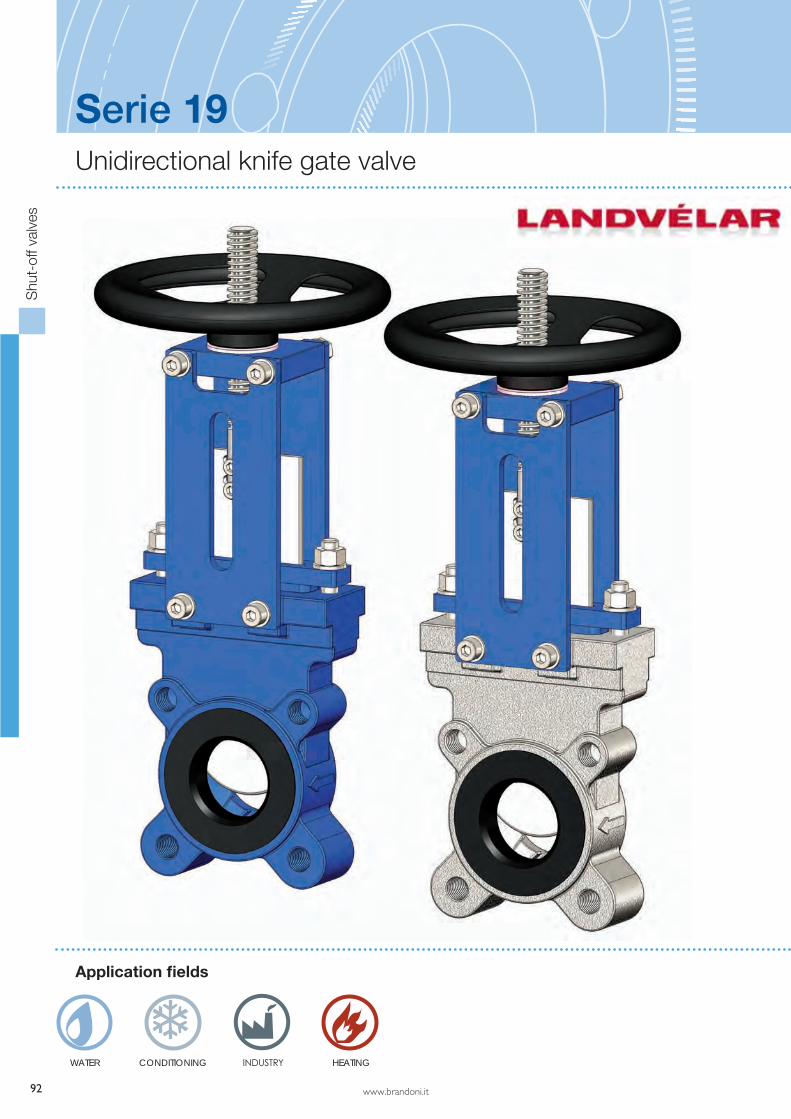
92 www.brandoni.it INDUSTRY Serie 19 Application fields Unidirectional knife gate valve WATER CONDITIONING Shut-off valves HEATING
Transcript of Unidirectional knife gate valve...V 175 175 225 225 225 300 300 300 400 400 400 500 500 500 F EN...
92 www.brandoni.it
INDUSTRY
Serie 19
Application fields
Unidirectional knife gate valve
WATER CONDITIONING
Shu
t-of
f val
ves
HEATING
www.brandoni.it
Serie 19
Construction and testing norms (correspondences):
Face-to-face: EN 558-1Flanges: EN 1092Marking: EN19Testing: 100% testing in accordance with EN 12266
The bidirectional knife gate valves in Series 19, with a cast iron or stainless steel body, are produced in conformity with
severe product norms and with EN ISO 9001 quality requirements.
They are available with various seals and, on request, may be manufactured with a square shape.
These valves are suitable for water plants, pneumatic plants, waste water and purification plants, and for the chemical
and food industries. Furthermore, they are suitable for handling viscous liquids or liquids with solid parts in suspension.
(Please ensure the choice of the corresponding item).
The seals are available in different materials, which correspond to the various fluids to be carried.
These valves are supplied, as standard, with a rising stem. On request, they can be equipped with a non-rising stem, as
well as with a wide range of actuators and accessories available for this series.
YES: for choking and regulation of the flow. Self-cleaning.
Accessories Actuator and drives
V-port
Mechanical limit switches
Chain driver
Square cap
Knife protection for pneumatic actuator
Conical deflector
Solenoid valve for pneumatic actuator
Pneumatic and electric actuators
Gear boxes
Chain driver
Operation lever
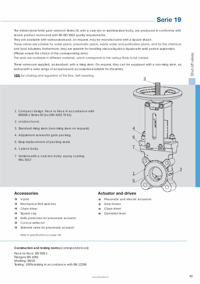
1. Compact design. Face to Face in accordance with EN558-1 Series 20 (ex DIN 3202 T3 K1).
2. Unidirectional.
3. Standard rising stem (non-rising stem on request).
4. Adjustment screws for gate packing.
5. Easy replacement of packing seals.
6. 1 piece body.
7. Versions with a cast iron body: epoxy coating RAL 5017.
Shu
t-of
f val
ves
12
3
5
4
6
7
Refer to specifications on page 104
93
94 www.brandoni.it
H1
FH
n° x M
13
12
9
14
3
6
10
1
2
7
8
11
5
4
DN
A
V
Shu
t-of
f val
ves
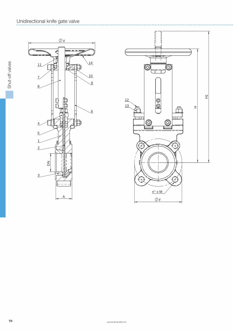
Unidirectional knife gate valve

www.brandoni.it
Shu
t-of
f val
ves
123456789
1011121314
-
Component
BodyGateSealPacking glandPackingPlatesBearingStemNutSliding washerStudPacking adjustment stud boltPacking adjustment nutHand wheelBolts
Material
EN GJL 250 / CF8MAISI 316Butyl / NBR / EPDM / FKM / PTFE / metal - metalEN GJS 400-15 PTFE + EPDMDuctile iron, epoxy coatedDuctile iron, epoxy coated AISI 316BronzePTFEAISI 304AISI 304AISI 304Ductile iron, epoxy coatedAISI 304
Materials
Dimensions (mm)
Weight (kg)
DN 50 65 80 100 125 150 200 250 300 350 400 450 500 600A EN 558/1-20 43 46 46 52 56 56 60 68 78 96 100 106 110 110H 301 338 366 393 446 548 659 733 870 924 1020 1119 1250 1430H1 361 411 448 495 573 699 860 984 1172 1276 1423 1562 1758 2038V 175 175 225 225 225 300 300 300 400 400 400 500 500 500F EN 1092/2 PN10 125 145 160 180 210 240 295 350 400 460 515 565 620 725n° x M EN 1092/2 PN10 4 x M16 4 x M16 8 x M16 8 x M16 8 x M16 8 x M20 8 x M20 12 x M20 12 x M20 16 x M20 16 x M24 20 x M24 20 x M24 20 x M27
kg 5 6 9 11 13 22 33 53 65 118 133 203 223 298
Serie 19
95
96 www.brandoni.it
DN
80
50 60 70 9080 100 % Opening
10
20
DN
450
10 40
m H2O
40000100 1000 10000 mc/h
40
60
80
100
10
0,2
DN
50
DN
65
30
DN
100
DN
125
% F
low
rate
DN
150
DN
250
DN
200
DN
300
DN
350
DN
400
DN
500
DN
600
20
1
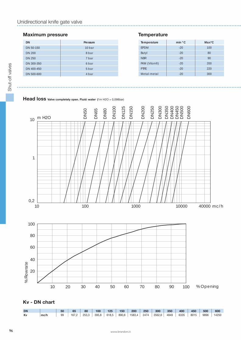
Head loss Valve completely open. Fluid: water (1m H2O = 0,098bar)
Maximum pressure TemperatureDN Pressure
10 bar
8 bar
7 bar
6 bar
5 bar
4 bar
Temperature min ° C Max°C
EPDM -20 100
Butyl -20 80
NBR -20 90
FKM (Viton®) -20 200
PTFE -20 220
Metal- metal -20 300
DN 50-150
DN 200
DN 250
DN 300-350
DN 400-450
DN 500-600
DN 50 65 80 100 125 150 200 250 300 350 400 450 500 600Kv mc/h 99 167,2 253,3 395,8 618,5 890,6 1583,4 2474 3562,6 4849 6335 8015 9896 14250
Kv - DN chart
Shu
t-of
f val
ves
Unidirectional knife gate valve

www.brandoni.it
Cast iron body
AISI 316 body
Versions
19.600
Body: AISI 316Gate: AISI 316 Seal: ButylTemp: -20 +80°C
19.606
Body: AISI 316Gate: AISI 316 Seal: metal-metalTemp: -20 +300°C
19.601
Body: AISI 316Gate: AISI 316 Seal: NBRTemp: -20 +90°C
19.609
Body: AISI 316Gate: AISI 316 Seal: EPDMTemp: -20 +100°C
19.602
Body: AISI 316Gate: AISI 316 Seal: FKMTemp: -20 +200°C
Coating: RAL 5017 colour
19.000
Body: EN GJL 250Gate: AISI 316 Seal: ButylTemp: -20 +80°C
19.001
Body: EN GJL 250Gate: AISI 316 Seal: NBRTemp: -20 +90°C
19.006
Body: EN GJL 250Gate: AISI 316 Seal: metal-metalTemp: -20 +300°C
19.009
Body: EN GJL 250Gate: AISI 316 Seal: EPDMTemp: -20 +100°C
19.603
Body: AISI 316Gate: AISI 316 Seal: PTFETemp: -20 +220°C
Shu
t-of
f val
ves
Serie 19
97

104 www.brandoni.it
Knife gate valves
Shu
t-of
f val
ves
Accessories for series 18 - 19 - 23
For series 19 - 23
For series 18
V-port
Chain driver
Hand-Protection for pneumatic actuator
Scraper
Mechanical limit switches
Square cap
Conical deflector

www.brandoni.it
Serie 18 - 19 - 23
105
Counterflange
Shu
t-of
f val
ves
The information provided here is delivered with each product, and contains “Instructions for use and maintenance”; it is also available on our website: www.brandoni.it (download section)
HOw TO CHOOSE THE VALVEThe operation area of the valve is limited to given temperatures and fluid types, depending on the material of the seal. It is important to communicate the working temperature and pressure and the medium, in order to be sure that the valve is suitable for the application.
Some indications for choosing the seal:EPDM - Advantages: It has excellent resistance to heat, ozone and sunlight, very good flexibility at low temperatures, good resistance to alkalis, acids, oxygenated solvents and very good resistance to water and steam. Limits: poor resistance to oil, gasoline and all hydrocarbon-based solvents.Maximum continuous operating temperature -20 /+100°C.NBR - Advantages: excellent resistance to oil and mineral lubricants, good resistance to gasoline, alkalis, acids, hydrocar-bon-based solvents. Limits: poor resistance to ozone and to aromatic hydrocarbonsMaximum continuous operating temperature -20 /+90°C.BUTYL (natural rubber) Advantages: this category includes elastomers made from natural rubber. High resistance to exten-ding, great resistance to tearing and abrasions and good flexibility at lower temperatures. Maximum continuous operating temperature -20/+ 80ºC. FKM (Viton®) - Advantages: excellent resistance to ozone and sunlight, lubricant oils and hydrocarbons. Poor flexibility at lower temperatures. Good resistance to alkalis, acids and hot water. Not suitable for steam.Maximum continuous operating temperature -20/+ 200ºC.PTFE - Advantages: excellent resistance to a wide range of media materials. Maximum continuous operating temperature -20/+ 220ºC.
STORAGE AND TRANSPORT- Keep in dry and closed place. Avoid exposure of the elastomeric parts to sunlight.- For art. 18.000 and 19.000: during storage, the gate has to be partially open in order to prevent damage to the elastomeric part.- Avoid knocks, especially to the delicate parts (lever, hand wheel, gear boxes/actuators). Do not use the weaker parts (lever, hand wheel) to lift the valve.
INSTALLATION- Handle with care.- The valve is suitable for installation with the stem axis in a vertical or horizontal position. For valves with pneumatic actua-tors, for mounting with the stem axis horizontal, an appropriate support is needed (fig. 1) for DN >200.- The mounting has to be made between flanges. In case of end of line installation, a counter flange MUST be mounted (fig. 2).
Instruction and Recommendations for series 18 - 19 - 23
FIG. 1
Support
FIG. 2

106 www.brandoni.it
- Clean the surfaces of contact carefully.- Use flat gaskets suitable for the working temperature and medium type, as indicated below: Series 18.000: 2 gaskets Series 19.000: 1 gasket for DN50-300. 2 gaskets for DN350-600 Series 23.000: NO gaskets for DN50-300. 2 gaskets for DN350-600
- Avoid the presence of protrusions and sharp edges of the piping, in order not to damage the surface of the valve lining.- Do not weld the flanges to the piping after installing the valve.- Chose a screw of the correct length: if the screw too long, it will not be possible to tighten it sufficiently. Assemble as shown in Fig. 3 b or 3 c. Tighten bolts crosswise.
- Avoid inclination, twisting and misalignments of the piping which might subject the valve to unwanted stresses, once it has been installed. Water hammers might cause damage and ruptures. It is recommended that such conditions should be avoided, or elastic joints be used, in order to reduce such effects. The joints have to be mounted to obtain a rubber on metal contact (for series 19.000 and 23.000 avoid mounting the joint directly on the valve lining).The valves in Series 19.000 are unidirectional. Respect the flow direction indicated by the arrow on the body. If a conical deflector is installed, ensure that it is installed in the flow direction for correct operation.
Closure is achieved by turning clockwise, the approximate number of turns for complete opening/closing of the valve is:
For manual or electrical actuation of the valve, once the valve has been installed, grease the nut and screw with a water-repellent grease (for example silicon grease or Molykote) in order to avoid seizures.While putting the valve into operation, and periodically during its life span, it is recommended that the seals between the gate and body, and those in the upper part of the valve (also in the lower part for series 23.000) be checked. During valve assembly, the packing gland bolts are tightened with a standard torque. However, depending on the pressure and other service conditions, if a leakage from upper part of the valve should be spotted, it may be necessary to tighten these bolts further. Cross tighten the bolts and respect the torque values indicated in the “Maintenance” section.
wARNING FOR VALVES wITH PNEUMATIC ACTUATORBSP 3/8” G for DN50-65 and BSP 1/2” G for DN80-600 threads are provided for air supply connection.Air supply pressure must be between 6 and 10 bar.In order to ensure correct closure, a supply pressure of minimum 6 bar is recommended. NB: Pressure below 6 bar may cause the valve to open/close too slowly, as well as incomplete closure.The air supply to the actuator must have previously been filtered, dehumidified and lubricated.
Capacity of cylinder (litres of air at 1 bar of pressure) is:
RECOMMENDATIONS FOR VALVES wITH ELECTRIC ACTUATORThe user must follow the instructions for using and maintaining the actuator.Valves with an electric actuator (especially those with modulating actuators) must be checked and lubricated every week.
SERIES DN 50 65 80 100 125 150 200 250 300 350 400 450 500 60018 - 23 No. of turns 14 17.5 21 26 32.5 31 41 51 61 71 81 65 72 8619 No. of turns 16 19 23 28 34 33 43 53 63 73 83 67 74 88
DN 50 65 80 100 125 150 200 250 300 350 400 450 500 600Ф cylinder 80 80 100 100 125 160 190 190 190 250 250 300 300 300Litres 0.35 0.43 0.72 0.97 1.87 3.48 6.44 7.85 9.25 18.61 21.25 34.07 37.68 44.75
Knife gate valves
Shu
t-of
f val
ves
Fig. 3c OKFig. 3b OKFig. 3a NO
Flange Valve
FIG. 3a NO FIG. 3b YES FIG. 3c YES

www.brandoni.it
Serie 18 - 19 - 23
107
MAINTENANCENB: OPERATING ON A LINE UNDER PRESSURE MIGHT CAUSE INJURY AND DAMAGE TO THE PLANT. Before dismantling or maintaining the plant:Ensure that the pipes, valves and fluids have cooled down, the pressure has decreased and the lines and pipes have been drained in case of toxic, corrosive, inflammable or caustic liquids.
It is recommended that the valve be opened/closed at least twice a year to check that it works properly. It is important to plan periodic inspections to check for any leakages between the body and gate and to verify the conditions of the elastomer seal. In the case of leakages, the packing adjustment screws may be tightened a little. In the event of it being necessary to replace the seals, proceed as indicated here below:
REPLACING THE SEALS, SERIES 18.000 (fig. 4)
a. Dismantle the valve from the plant.b. Remove the screws (1) fixing the stem to the gate.c. Remove the screws (2) fixing the plates (3) to the body (5).d. Remove the upper part of the valve.e. Remove the screws (4) and split the 2 semi bodies (5).f. Check the condition of the “U” seal (6) between the 2 parts of the semi bodies and replace it, if necessary.g. Check the conditions of the seals (7) between the body and gate, located in the upper part of the semi bodies and replace them, if necessary.h. Assemble the 2 parts of the semi bodies, installing the “U” seal.
The torque for tightening the screws is:
i. Re-assemble the valve, carrying out points a-d above, in reverse order.j. Grease the nut and screw with neutral, water-repellent grease (for example, silicone grease or Molykote).k. Before putting the valve back in operation, carry out a hydrostatic test, if possible.l. Check the seal between the body and gate in the upper part of the valve while putting the valve in operating.
In the event of leaks, the adjustment screws (9) may be tightened a little; tighten the screws crosswise and do not exceed the indicated torque. To finish, fix with counter nuts.
DN 50 65 80 100 125 150 200 250 300 350 400 450 500 600Torque min (Nm) 2.5 2.8 3.2 3.6 3.6 4.3 4.5 5.0 6.0 8.5 10 14 15 27Torque max (Nm) 3.6 3.6 4.5 5.0 5.0 5.8 6.0 6.8 8.2 11 13 16 19 32
DN 50 65 80 100 125 150 200 250 300 350 400 450 500 600Torque (Nm) 40 40 40 40 40 75 75 75 75 75 75 75 120 120
2
7
3 7
6
5
1
8
5
9
9
FIG. 4
Shu
t-of
f val
ves
108 www.brandoni.it
3
5
6
1
2
84
7
9
FIG. 5
5a. Packing layout details
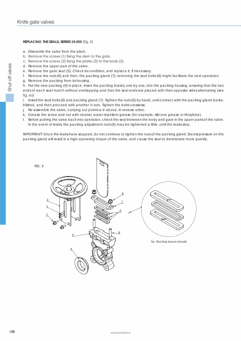
REPLACING THE SEALS, SERIES 19.000 (fig. 5)
a. Dismantle the valve from the plant.b. Remove the screws (1) fixing the stem to the gate.c. Remove the screws (2) fixing the plates (3) to the body (5).d. Remove the upper part of the valve.e. Remove the gate seat (5). Check its condition, and replace it, if necessary.f. Remove the nuts (6) and then, the packing gland (7); removing the stud bolts (8) might facilitate the next operation.g. Remove the packing from its housing.h. Put the new packing (9) in place. Insert the packing braids, one by one, into the packing housing, ensuring that the two ends of each seal match without overlapping and that the seal ends are placed with their opposite sides alternating (see fig. 6a)i. Install the stud bolts (8) and packing gland (7). Tighten the nuts (6) by hand, until contact with the packing gland is esta-blished, and then proceed with another ½ turn. Tighten the bolts crosswise.j. Re-assemble the valve, carrying out points a-d above, in reverse order.k. Grease the screw and nut with neutral, water-repellent grease (for example, silicone grease or Molykote).l. Before putting the valve back into operation, check the seal between the body and gate in the upper parts of the valve. In the event of leaks, the packing adjustment nuts (6) may be tightened a little, until the leaks stop.
IMPORTANT: Once the leaks have stopped, do not continue to tighten the nuts of the packing gland. Excess pressure on the packing gland will result in a high operating torque of the valve, and cause the seal to deteriorate more quickly.
Knife gate valves
Shu
t-of
f val
ves
www.brandoni.it
9
5
73
1
2
5
84
6
Serie 18 - 19 - 23
109
FIG. 6
6a. packing layout details
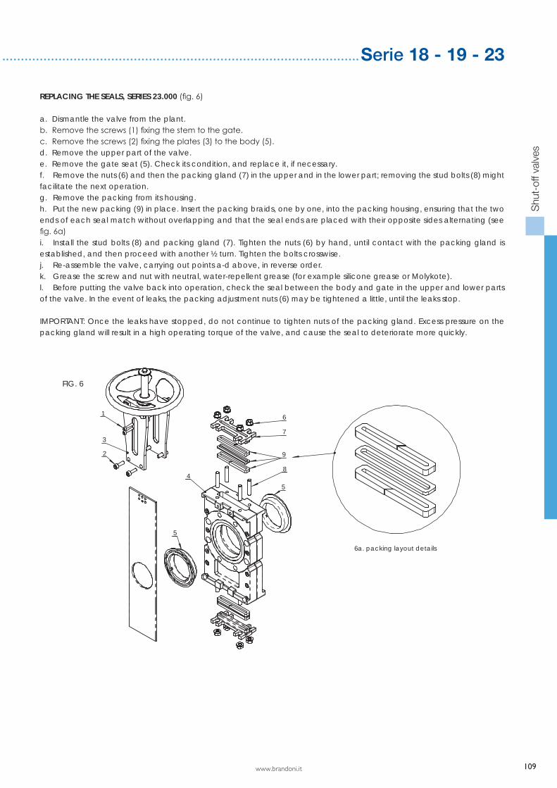
REPLACING THE SEALS, SERIES 23.000 (fig. 6)
a. Dismantle the valve from the plant.b. Remove the screws (1) fixing the stem to the gate.c. Remove the screws (2) fixing the plates (3) to the body (5).d. Remove the upper part of the valve.e. Remove the gate seat (5). Check its condition, and replace it, if necessary.f. Remove the nuts (6) and then the packing gland (7) in the upper and in the lower part; removing the stud bolts (8) might facilitate the next operation.g. Remove the packing from its housing.h. Put the new packing (9) in place. Insert the packing braids, one by one, into the packing housing, ensuring that the two ends of each seal match without overlapping and that the seal ends are placed with their opposite sides alternating (see fig. 6a)i. Install the stud bolts (8) and packing gland (7). Tighten the nuts (6) by hand, until contact with the packing gland is established, and then proceed with another ½ turn. Tighten the bolts crosswise.j. Re-assemble the valve, carrying out points a-d above, in reverse order.k. Grease the screw and nut with neutral, water-repellent grease (for example silicone grease or Molykote).l. Before putting the valve back into operation, check the seal between the body and gate in the upper and lower parts of the valve. In the event of leaks, the packing adjustment nuts (6) may be tightened a little, until the leaks stop.
IMPORTANT: Once the leaks have stopped, do not continue to tighten nuts of the packing gland. Excess pressure on the packing gland will result in a high operating torque of the valve, and cause the seal to deteriorate more quickly.
Shu
t-of
f val
ves