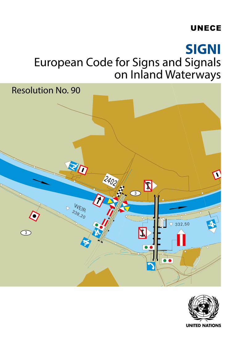
UNECE SIGNI European Code for Signs and Signals on Inland ...
222
3 3 2402 SIGNI European Code for Signs and Signals on Inland Waterways Resolution No. 90
Transcript of UNECE SIGNI European Code for Signs and Signals on Inland ...
3
3
2402
UN
ITED N
ATION
S
SIGNIEuropean Code for Signs and Signals
on Inland WaterwaysResolution No. 90
SIGN
I European Code for Signs and Signals on Inland Waterw
aysU
NECE

New York and Geneva, 2018
ECONOMIC COMMISSION FOR EUROPE
SIGNIEuropean Code
for Signs and Signals on Inland Waterways
Resolution No. 90

Note
The designations employed and the presentation of the material in this publication do not imply the expression of any opinion whatsoever on the part of the Secretariat of the United Nations concerning the legal status of any country, territory, city or area, or of its authorities, or concerning the delimitation of its frontiers or boundaries.
Copyright © United Nations, 2018
All rights reserved.
No part of this publication may, for sales purposes, be reproduced, stored in a retrieval system or transmitted in any form or by any means, electronic, electrostatic, magnetic tape, mechanical,
photocopying or otherwise, without prior permission in writing from the United Nations.
ECE/TRANS/SC.3/208
UNITED NATIONS PUBLICATIONSales No. E.19.II.E.1
ISBN 978-92-1-117179-2eISBN 978-92-1-047419-1
Cover: Photo credit: Federal Waterways and Shipping Agency (WSV), GermanyPhoto credit (all photos): @ iStock

iii
United Nations Economic Commission for Europe
The United Nations Economic Commission for Europe (UNECE) is one of the five United Nations regional commissions, administered by the Economic and Social Council (ECOSOC). It was established in 1947 with the mandate to help rebuild post-war Europe, develop economic activity and strengthen economic relations among European countries, and between Europe and the rest of the world. During the Cold War, UNECE served as a unique forum for economic dialogue and cooperation between East and West. Despite the complexity of this period, significant achievements were made, with consensus reached on numerous harmonization and standardization agreements.
In the post-Cold War era, UNECE acquired not only many new member States, but also new functions. Since the early 1990s the organization has focused on analyses of the transition process, using its harmonization experience to facilitate the integration of Central and Eastern European countries into the global markets.
UNECE is the forum where the countries of western, central and eastern Europe, central Asia and North America – 56 countries in all – come together to forge the tools of their economic cooperation. That cooperation concerns economics, statistics, environment, transport, trade, sustainable energy, timber and habitat. The Commission offers a regional framework for the elaboration and harmonization of conventions, norms and standards. The Commission’s experts provide technical assistance to the countries of South-East Europe and the Commonwealth of Independent States. This assistance takes the form of advisory services, training seminars and workshops where countries can share their experiences and best practices.

iv
Transport in UNECE
The UNECE Sustainable Transport Division is the secretariat of the Inland Transport Committee (ITC) and the ECOSOC Committee of Experts on the Transport of Dangerous Goods and on the Globally Harmonized System of Classification and Labelling of Chemicals. The ITC and its 17 working parties, as well as the ECOSOC Committee and its sub-committees are intergovernmental decision-making bodies that work to improve the daily lives of people and businesses around the world, in measurable ways and with concrete actions, to enhance traffic safety, environmental performance, energy efficiency and the competitiveness of the transport sector.
The ECOSOC Committee was set up in 1953 by the Secretary-General of the United Nations at the request of the Economic and Social Council to elaborate recommendations on the transport of dangerous goods. Its mandate was extended to the global (multi-sectoral) harmonization of systems of classification and labelling of chemicals in 1999. It is composed of experts from countries which possess the relevant expertise and experience in the international trade and transport of dangerous goods and chemicals. Its membership is restricted in order to reflect a proper geographical balance between all regions of the world and to ensure adequate participation of developing countries. Although the Committee is a subsidiary body of ECOSOC, the Secretary-General decided in 1963 that the secretariat services would be provided by the UNECE Sustainable Transport Division.
ITC is a unique intergovernmental forum that was set up in 1947 to support the reconstruction of transport connections in post-war Europe. Over the years, it has specialized in facilitating the harmonized and sustainable development of inland modes of transport. The main results of this persevering and ongoing work are reflected, among other things, (i) in 58 United Nations conventions and many more technical regulations, which are updated on a regular basis and provide an international legal framework for the sustainable development of national and international road, rail, inland water and intermodal transport, including the transport of dangerous goods, as well as the construction and inspection of road motor vehicles; (ii) in the Trans-European North-south Motorway, Trans-European Railway and the Euro-Asia Transport Links projects, that facilitate multi-country coordination of transport infrastructure investment programmes; (iii) in the TIR system, which is a global customs transit facilitation solution; (iv) in the tool called For Future Inland Transport Systems (ForFITS), which can assist national and local governments to monitor carbon dioxide (CO2) emissions coming from inland transport modes and to select and design climate change mitigation policies, based on their impact and adapted to local conditions; (v) in transport statistics – methods and data – that are internationally agreed on; (vi) in studies and reports that help transport policy development by addressing timely issues, based on cutting-edge research and analysis. ITC also devotes special attention to Intelligent Transport Services (ITS), sustainable urban mobility and city logistics, as well as to increasing the resilience of transport networks and services in response to climate change adaptation and security challenges.
In addition, the UNECE Sustainable Transport and Environment Divisions, together with the World Health Organization (WHO) – Europe, co-service the Transport Health and Environment Pan-European Programme (THE PEP).
Finally, as of 2015, the UNECE Sustainable Transport Division is providing the secretariat services for the Secretary General’s Special Envoy for Road Safety Mr. Jean Todt.

v
Foreword
Since its establishment by the Inland Transport Committee of the United Nations Economic Commission for Europe (UNECE) in 1956, the Sub-Committee on Inland Water Transport, (the Working Party on Inland Water Transport, or SC.3 since 1970) has focused on developing and maintaining harmonized navigation rules in order to facilitate traffic on inland waterways and ensure safety. These rules cover the European Code for Inland Waterways (CEVNI) and the signs and signals on inland waterways.
SC.3 adopted Resolution No. 1 of 28 August 1957 on the Standardization of Signalling Systems on Inland Waterways, with a purpose of establishing a homogeneous system of signs, signals and marking on inland waterways harmonized with the maritime buoyage system. This was subsequently replaced in 1982 by Resolution No. 22 “SIGNI – Signs and Signals on Inland Waterways”, after the adoption of a new maritime buoyage system by the International Association of Marine Aids to Navigation and Lighthouse Authorities (IALA). Resolution No. 22 was then subsequently revised in 2005 and 2010.
Following the decision of SC.3 at its sixtieth session in 2016 on the revision of SIGNI, the provisions have been significantly updated and brought in line with the fifth revision of CEVNI. This work has been accomplished with the participation of River Commissions and the CEVNI Expert Group as well as contributions from the Chairs of the Joint International VTT and Inland ECDIS Expert Group and IALA.
The European Code for Signs and Signals on Inland Waterways (SIGNI) provides recommendations for the competent authorities for the installation and application of buoyage and marking on European inland waterways contained in the fifth revision of CEVNI (ECE/TRANS/SC.3/115/Rev.5).
This new edition of SIGNI is based on revision 2 of Resolution No. 22, and the Guidelines for Waterways Signs and Marking (Resolution No. 59, revision 2). The present SIGNI replaces the annex to Resolution No. 22 as amended by resolutions Nos. 29, 51 and 67 (ECE/TRANS/SC.3/108/Rev.2) and the annex to Resolution No. 59 as amended by Resolutions Nos. 75 and 85 (ECE/TRANS/SC.3/169/Rev.2). It contains two new chapters on the monitoring of signs and marking by AIS aids to navigation (chapter 13) and on the regional and national special requirements (chapter 14).

vi
Contents
SIGNI – European Code for Signs and Signals on Inland Waterways – Resolution No. 90 ............... x
Annex to Resolution No. 90 EUROPEAN CODE FOR SIGNS AND SIGNALS ON INLAND WATERWAYS (SIGNI) .................................. 1
Chapter 1 - General ........................................................................................................................................1
1.1 General principles ............................................................................................................................................................................................... 1
1.2 Lights .......................................................................................................................................................................................................................... 3
1.3 Boards and buoys ............................................................................................................................................................................................... 3
1.4 Geographical limits of applicability of the marking system recommended ................................................................. 3
Chapter 2 - Visibility of signs and lights ..................................................................................................... 5
2.1 General provisions............................................................................................................................................................................................. 5
2.2 Conditions of visibility and dimensions of signs ............................................................................................................................. 5
2.3 Conditions for the visibility of lights and lighting .......................................................................................................................... 7
2.4 Obligation not to hinder road and rail traffic .................................................................................................................................... 7
Chapter 3 - Buoyage and marking of the waterway ................................................................................9
3.1 Requirements to be met by signs and marks and their marking plan .............................................................................. 9
3.2 Buoyage of fairway limits in the waterway .......................................................................................................................................10
3.3 Buoyage and marking of danger points and obstacles ............................................................................................................12
3.4 Bank marks indicating the position of the fairway .......................................................................................................................17
3.5 Buoyage and marking of lakes and broad waterways ...............................................................................................................18
3.6 Additional marking for navigation by radar .....................................................................................................................................20
3.7 Buoys for miscellaneous purposes .........................................................................................................................................................21
3.8 Warning posts .....................................................................................................................................................................................................21
Chapter 4 - Buoyage and marking of lakes and broad waterways .....................................................23
4.1 General ....................................................................................................................................................................................................................23
4.2 Marking of danger points, obstacles and special features ......................................................................................................23
4.3 Marking of the axis of a channel, the middle of a channel or a landfall .........................................................................25
4.4 Special marks .......................................................................................................................................................................................................26
4.5 Weather signs and signals on lakes .......................................................................................................................................................26
4.6 Example of signs and signals on lakes and broad waterways ..............................................................................................26
Chapter 5 - Lights .........................................................................................................................................29
5.1 Definitions .............................................................................................................................................................................................................29
5.2 Fixed lights ............................................................................................................................................................................................................29
5.3 Rhythmic lights ..................................................................................................................................................................................................31
5.4 Additional luminous signal .........................................................................................................................................................................31
5.5 Semaphores .........................................................................................................................................................................................................31
Contents

vii
Chapter 6 - Installation of signs and marking in characteristic sections of the river ......................33
6.1 General ....................................................................................................................................................................................................................33
6.2 Marking of meandering sectors...............................................................................................................................................................35
6.3 Marking of shoals ..............................................................................................................................................................................................38
6.4 Marking of the vicinity of bridges and passages through bridges ....................................................................................40
6.5 Installation of floating signs restricting berthing points ...........................................................................................................42
6.6 Reference numbers on buoys and marker posts ..........................................................................................................................42
Chapter 7 - Marking of harbour entrances ..............................................................................................45
Chapter 8 - Marking of permanent structures ........................................................................................47
8.1 General principle ...............................................................................................................................................................................................47
8.2 Fixed bridges ........................................................................................................................................................................................................48
8.3 Movable bridges ................................................................................................................................................................................................49
8.4 Weirs ..........................................................................................................................................................................................................................50
8.5 Locks, ship lifts and inclined planes .......................................................................................................................................................51
Chapter 9 - Blockage of the waterway .....................................................................................................53
9.1 Suspension of navigation for all vessels ..............................................................................................................................................53
9.2 Prohibition of navigation for motorized vessels ............................................................................................................................53
9.3 Prohibition to enter or leave a harbour or a tributary waterway ........................................................................................53
Chapter 10 - Marking of prohibited or restricted zones .......................................................................55
Chapter 11 - Variable message signs to regulate traffic ........................................................................57
Chapter 12 - Installation of radar reflectors ............................................................................................59
12.1 Installation of radar reflectors on marking signs and signals and navigable passes through bridges ........59
12.2 Buoys and poles with radar reflectors ..................................................................................................................................................60
12.3 Marking of overhead cables (where applicable) ...........................................................................................................................60
Chapter 13 - Monitoring of signs and marking by AIS Aids to Navigation........................................63
13.1 Function of AIS Aids to Navigation ........................................................................................................................................................63
13.2 Types of AIS Aids to Navigation ...............................................................................................................................................................63
Chapter 14 - Regional and national special requirements ...................................................................65
14.1 Introduction .........................................................................................................................................................................................................65
14.2 Chapter 1 - General ..........................................................................................................................................................................................65
14.3 Chapter 2 - Visibility of signs and lights ..............................................................................................................................................65
14.4 Chapter 3 - Buoyage and marking of the waterway ...................................................................................................................65
14.5 Chapter 5 - Lights ..............................................................................................................................................................................................66
14.6 Chapter 6 - Installation of signs and marking in characteristic sections of the river ..............................................67
14.7 Chapter 7 - Marking of harbour entrances .......................................................................................................................................67
Contents

viii
14.8 Chapter 8 - Marking of permanent structures ................................................................................................................................67
14.9 Chapter 9 - Blockage of the waterway ................................................................................................................................................67
14.10 Chapter 10 - Marking of prohibited or restricted zones ...........................................................................................................67
14.11 Chapter 12 - Installation of radar reflectors ......................................................................................................................................67
Appendix 1 - Minimal dimensions of the signs from annexes 7 and 8 of the European Code for Inland Waterways ......................................................................................................69
1. Visibility of signs .................................................................................................................................................................................................69
2. Minimal dimensions of the signs contained in annex 7 to the European Code for Inland Waterways ......71
2.1 Main signs ..............................................................................................................................................................................................................71
A. Prohibitory signs ......................................................................................................................................................................................71
B. Mandatory signs ......................................................................................................................................................................................93
C. Restrictive signs .....................................................................................................................................................................................108
D. Recommendatory signs ...................................................................................................................................................................116
E. Informative signs ..................................................................................................................................................................................121
2.2 Auxiliary signs ...................................................................................................................................................................................................171
A. Panels showing the distance at which the regulation applies or the special feature indicated by the main sign is to be found ..................................................................................................................................................171
B. Pointers showing the direction of the section to which the main sign applies ...........................................172
C. Panels giving explanations or additional information ..................................................................................................172
3. Minimal dimensions of the signs contained in annex 8 to the European Code for Inland Waterways ...173
3.1 Buoyage of fairway limits in the waterway ....................................................................................................................................173
A. Right-hand side of the waterway ...............................................................................................................................................173
B. Left-hand side of the waterway ..................................................................................................................................................173
C. Bifurcation of the waterway ..........................................................................................................................................................174
3.2 Bank marks indicating the position of the fairway ....................................................................................................................175
A. Bank marks indicating the position of the fairway in relation to the banks ....................................................175
B. Cross-overs ...............................................................................................................................................................................................177
3.3 Buoyage and marking of danger points and obstacles .........................................................................................................179
A. Fixed marks ..............................................................................................................................................................................................179
3.4 Radar reflectors on marking signs and signals and navigable passes through bridges ....................................182
A. Radar reflectors on bridges ............................................................................................................................................................182
B. Radar reflectors on buoys and signs ........................................................................................................................................183
Contents

ix
Appendix 2 - Properties of lights ................................................................................................................185
1. Categories of luminous intensity .........................................................................................................................................................185
2. Acceptable colours of lights ..................................................................................................................................................................185
3. Calculation of light range .........................................................................................................................................................................186
Appendix 3 - Colours of reflected light for navigation signs ............................................................ 189
Appendix 4 - Rhythmic lights .................................................................................................................. 193
Appendix 5 - Recommendations for the lighting of traffic signs ..................................................... 201
1. General provisions .........................................................................................................................................................................................201
2. External backward-facing lighting of signs ...................................................................................................................................201
3. Internally backlit signs.................................................................................................................................................................................202
Appendix 6 - Examples of variable-message traffic signs ................................................................. 205
1. Mechanical boards ........................................................................................................................................................................................205
A. Scrolling sign boards .........................................................................................................................................................................205
B. Trivision boards ......................................................................................................................................................................................205
C. Other mechanical boards ...............................................................................................................................................................205
2. Electronic boards............................................................................................................................................................................................206
A. Optical waveguide (optical fibre) boards ..............................................................................................................................206
B. Light-emitting diode (LED) matrix boards ............................................................................................................................207
C. Liquid crystal displays (LCDs) ........................................................................................................................................................207
Contents


xi
SIGNI – European Code for Signs and Signals on Inland Waterways
Resolution No. 90
(adopted by the Working Party on Inland Water Transport on 5 October 2018)
The Working Party on Inland Water Transport,
Desirous, in the interest of safety of navigation, of establishing rules for waterway signs and marking harmonized with the European Code for Inland Waterways (CEVNI), as well as regulations for their installation and visualization,
Having regard to its resolution No. 22, SIGNI: Signs and Signals on Inland Waterways, as amended by resolutions Nos. 29, 51 and 67 (ECE/TRANS/SC.3/108/Rev.2),
Having regard also to its resolution No. 59, containing in its annex the Guidelines for Waterway Signs and Marking, as amended by resolutions Nos. 75 and 85 (ECE/TRANS/SC.3/169/Rev.2),
Considering its resolution No. 24, concerning the European Code for Inland Waterways (CEVNI), as amended by resolutions Nos. 26, 27, 37, 39, 43-47, 54, 62, 66 and 81 (ECE/TRANS/SC.3/115/Rev.5),
Noting that, through the application of the recommendations of these resolutions by Governments and River Commissions, the corresponding regulations in force on European inland waterways have to a large extent been harmonized,
Acknowledging the desirability, for safety of navigation, of maintaining a system of signs and signals on inland waterways harmonized with the maritime system of buoyage,
Recognizing the role of modern technologies and innovations in ensuring navigation safety and their impact on the regulations in force,
Bearing in mind the reports of the Working Party on the Standardization of Technical and Safety Requirements in Inland Navigation on its fifty-first, fifty-second and fifty-third sessions (ECE/TRANS/SC.3/WP.3/102, para. 30, ECE/TRANS/SC.3/WP.3/104, paras. 31-32, and ECE/TRANS/SC.3/WP.3/106, paras. 31-34),
1. Decides to replace the text of SIGNI, as reproduced in ECE/TRANS/SC.3/108/Rev.2, and the Guidelines for Waterways Signs and Marking, as reproduced in ECE/TRANS/SC.3/169/Rev.2, by the annex to this resolution, entitled “SIGNI: European Code for Signs and Signals on Inland Waterways”, which is reproduced in ECE/TRANS/SC.3/208,
2. Decides to replace resolution No. 22, revision 2, resolution No. 59, revision 2, as well as resolutions Nos. 29, 51, 67, 75 and 85 by this resolution,
3. Invites Governments and River Commissions to inform the Executive Secretary of the United Nations Economic Commission for Europe whether they implement this resolution,
4. Requests the Executive Secretary of the United Nations Economic Commission for Europe to place the question of the application of this resolution periodically on the agenda of the Working Party on Inland Water Transport.


1Chapter 1 - General
Annex to Resolution No. 90
EUROPEAN CODE FOR SIGNS AND SIGNALS ON INLAND WATERWAYS (SIGNI)
Chapter 1 - General
1.1 General principles
1.1.1 In terms of the objective pursued, the marking comprises three categories of buoyage and marking:
(a) Buoyage of fairway limits in the waterway by means of buoys or spars, hereafter floating signs. This category will normally be used only on sections of waterway where the fairway cannot be indicated sufficiently clearly by marks placed on the banks;
(b) Buoyage and marking of danger points and obstacles, i.e. navigational hazards including:
• danger points, e.g. campshot, projections of the bank, low banks liable to flooding, fixed obstacles;
• obstacles, e.g. grounded or sunken vessels or floating equipment; work sites in the waterway, lost anchors, structures protruding into the fairway or in its vicinity etc.;
(c) Marks on land indicating the position of the fairway, hereafter bank marks, indicating the position of the fairway in relation to the banks and, where appropriate, its crossover from one bank to the other. The marks may also be used to provide isolated reference points for boatmasters.
1.1.2 Signs and signals comprise:
(a) Signs used to regulate navigation on the waterway, set out in section 3.5, chapter 5 and appendix 1, as well as annex 7 of the European code for inland waterways (CEVNI); and
(b) Floating signs and bank marks, set out in chapter 3 and annex 8 of CEVNI.
1.1.3 The signs set out in annex 7 to CEVNI are prohibitory, mandatory, restrictive, recommendatory and informative signs as well as auxiliary signs.
1.1.4 In the case of lakes and broad waterways, the three categories of buoyage and marking referred to above are used. In addition, special provisions are prescribed under chapter 4.
1.1.5 In accordance with article 5.01 of CEVNI, vessels’ crew members shall obey the requirements and take account of the recommendations or indications brought to their attention by these signs.
1.1.6 The number of signs, bank marks floating signs and their on-site locations shall meet the requirements of navigation safety.
1.1.7 In order to increase navigation safety, the competent authorities shall place kilometre markings along the inland waterway wherever waterway dimensions allow, as well as mark of each hectometre wherever possible.
1.1.8 Where the competent authorities decide to install a system of marking on a particular waterway or inland navigation network, they may:
• Select from among the marks covered by these provisions those which they deem suitable for the waterway or waterway network in question;
• Supplement the marks selected with additional marks not included in the system defined below, provided always that the shape and colour of such marks and the nature of any symbol employed

2 Chapter 1 - General
are consistent with the system and are such that the additional marks cannot be confused with any of the system’s existing marks.
In cases where these provisions permit alternatives, the competent authorities shall, unless there are overriding reasons to the contrary, agree on the alternative to be adopted on all of the several parts of the same waterway.
1.1.9 The choice of the marks and the establishment of their number depend on the local characteristics of the fairway and the function of each mark. Their installation shall be effected in cases when it is required by navigation criteria on the respective river section, in such a way as to ensure visibility from one mark to the next.
1.1.10 The term “left and right banks” means the sides of the waterway when moving from the source to the mouth.
On canals, lakes and broad waterways the competent authorities shall decide the matter in the light of local conditions. However, it is recommended that for canals the terms “right” and “left” should be defined as meaning to the right and to the left respectively of an observer facing in the direction in which the numbers indicated on successive kilometer markings rise.
1.1.11 The designations “right-hand side” and the “left-hand side” of the waterway or fairway are to be understood as for an observer facing downstream. On canals, lakes and broad waterways, the terms “right-hand side” and the “left-hand side” shall be defined by the competent authorities.
1.1.12 Aid to Navigation (AtoN) means a device, system, or service, external to a vessel, designed and operated to enhance safe and efficient navigation of all vessels and/or vessel traffic.
1.1.13 Where the prescribed mark consists of:
(a) Lights only: the lights may be used both by day and by night;
(b) Boards only: the boards may be used as night marks if illuminated;
(c) Boards and lights: by day, either boards or lights may be used; by night, either lights or illuminated boards may be used.
1.1.14 The marks shall be installed by the competent authorities which:
(a) Regularly observe the state of the river bed and the changes taking place in it and, on the basis of the results of these observations, correct the positioning of the signs and marks and, where necessary, add to them so that they indicate the fairway dimensions;
(b) Regularly measure the depth and the width of the marked fairway and provide boatmasters with the necessary information concerning minimum fairway depths and widths and the river level regime;
(c) Establish the plan for the installation of signs and marks (hereinafter the marking plan) in their respective sectors and establish the type and number of floating signs and bank marks to be used, in terms of the requirements of navigational safety and local conditions;
(d) Ensure as far as possible the uninterrupted operation of all floating signs and bank marks;
(e) Inform boatmasters in good time of the date of the installation and removal of signs, of all alterations of importance to navigation to their number, type, positioning and lighting, and the rules they establish permitting the passage of vessels in restricted sections where meeting and passing are prohibited.
1.1.15 The numbering of the sketches of signal signs and marks including lights corresponds to numbering given in annexes 7 and 8 of CEVNI.

3Chapter 1 - General
1.2 Lights
1.2.1 For the purpose of SIGNI and CEVNI, the following definitions are used:
• “Light”: a distinctive light used as a marking.
• “Fixed light”: an uninterrupted light of constant intensity and colour.
• “Rhythmic light”: a signal light that shows intermittently with a regular periodicity. The rhythmic character of such a light is the sequence of different appearances presented by the light during a period.
1.2.2 In principle, the use of rhythmic lights shall be reserved for the marking of the waterway. Rhythmic lights are described in appendix 4. Rhythmic lights shall also be used under the conditions specified in sections 3.2-3.4 and chapter 4.
1.2.3 In principle, the use of fixed lights shall be reserved for purposes other than those referred to in 1.2.2. For the meanings of the fixed lights recommended, see 5.2.2.
1.2.4 The luminous intensity of lights is established by the competent authorities in terms of local navigational conditions. In classifying the luminous intensity, it is recommended to use the classification of luminous intensity in appendix 2, which also includes calculations for luminous range.
1.2.5 In principle, the colours of lights should be in keeping with the standard of the International Commission on Illumination (CIE) (“Colours of Light Signals”, CIE S 004/E-2001, class A).
1.3 Boards and buoys
1.3.1 The recommended shape for boards bearing special signs is rectangular.
These boards are divided into two categories according to the signs they bear:
(a) Signs giving instructions: these shall be coloured white and bordered in red and display black symbols. Where they indicate a prohibition, the boards shall also bear a diagonal red bar;
(b) Signs giving information or indicating the end of an instruction for vessels proceeding in one direction only: all boards shall be rectangular and blue in colour, with white symbols.
1.3.2 The visibility of the boards may be improved by a narrow white border.
1.3.3 If necessary, these signs may be supplemented by additional boards, indicator plates, inscriptions referred to in 3.5.2 or additional luminous signals referred to in 5.4.
1.3.4 The chromaticity of the surface coatings of buoys and boards should lie within the chromaticity areas defined in the recommendations on the surface colours of visual signs and signals published by CIE (see 1.2.5). The back of the panel, if visible from the navigable zone, shall be of such a colour as not to be misleading.
1.4 Geographical limits of applicability of the marking system recommended
1.4.1 The competent authorities shall if necessary determine the boundaries between inland waterways (to which the recommended marking system applies) and maritime waterways.
1.4.2 The principles of the Aids to Navigation system of the International Association of Marine Aids to Navigation and Lighthouse Authorities (IALA) have been taken, where applicable to inland waterways, as the basis for the following provisions. These provisions have been defined in such a way as to avoid, as far as possible, any risk of conflict or confusion between the two systems of buoyage.


5Chapter 2 - Visibility of signs and lights
Chapter 2 - Visibility of signs and lights
2.1 General provisions
2.1.1 Whatever the position of the vessel in relation to the sign or the marker light, the characteristics of the sign or light shall remain unchanged. For daytime signs, these characteristics are: the form (topmark) and the colour; for signs at night: the type and colour of the lights.
2.1.2 The forms and the colours of the topmarks and the types and colours of the lights are set out in detail in sections 3.2-3.4 and their minimal dimensions are set out in appendix 1.
2.1.3 The basic requirement to be met by signs and marking is the guarantee of good visibility of all signs and lights by day and by night.
2.1.4 In accordance with the recommendations of IALA,1 there are three degrees of visibility of signs:
(a) First: the sign is visible to the naked eye. The meaning of the sign is not yet identifiable (simply visible);
(b) Second: when the sign is clearly visible and identifiable according to the present provisions and in CEVNI (identifiable);
(c) Third: the sign is identifiable and distinguishable from its surrounding background (conspicuous).
Signs that must be seen by a boatmaster at some imperative distance (“no entry”, “keep a particular sharp lookout”, etc.) must have a visibility (due to their proper dimensions) of second or third degree. The type and dimensions of signs should be selected accordingly.
Third degree visibility is required when the sign or light is identifiable in principle, but cannot be easily seen at night owing to the surrounding background (presence of construction or a large number of light sources).
2.1.5 The degree of visibility of signs and lights depends on the following conditions:
• Signs:
• Angle of sight;
• Colour contrast and differences;
• Lighting (including natural day light) and weather conditions.
• Lights:
• Luminous intensity;
• Competing lights and background lighting;
• Weather conditions.
2.2 Conditions of visibility and dimensions of signs
2.2.1 In order to ensure the first degree visibility, in daytime the sign shall be visible with an angle of more than 1’ (angular minute) and with sufficient contrast in relation to the environment. Detailed form and colour of the sign (second and third degree visibility) can only be distinguished with a larger angle of sight or with a reduction in the distance L to the object being observed.
1 IALA Guideline No. 1094 — On Daymarks for Aids to Navigation, Edition 1, December 2012.

6 Chapter 2 - Visibility of signs and lights
2.2.2 The minimal angle of distinction in daytime for simple shapes (cylinder, cone, sphere, etc.) is between 3 and 5 angular minutes, and for complex shapes (numbers, letters, etc.) between 5 and 8 angular minutes. For the boatmaster to be able to recognize the daymark (without any optical aids) at appropriate distances and visibility, the following formula can be used for the calculation of the required minimum dimensions of simple and complex shapes (see figure 2.1):
H= L ∙ tg α ≅ L ∙ sin α,
where:
H (m) — height of the sign;
L (m) — distance to the sign;
α (’) — viewing angle.
Figure 2.1
α
L
H
Values for H (m) as a function of L (m) and α (’) are presented in table 2.1.
Table 2.1
α (’)
L (m)
500 1 000 2 000 3 000 4 000
For signs of simple shapes (cylinder, cone, circle, etc.)
3 0.44 0.87 1.74 2.61 2.48
4 0.58 1.16 2.32 3.48 4.64
5 0.73 1.45 2.90 4.35 5.80
Table 2.1 shows that a shape of a sign with dimension H = 0.5 m is recognizable at distance L = 500 m and viewing angle α = 4’; when L = 1,000 m, then H = 1 m, etc.
When there are simple drawings (dot, line, arrow) on the signs, a 15 per cent visibility reduction must be taken into account, while with complex drawings it shall be 30 per cent.
2.2.3 Examples of the minimum measurements for the signs, marks and buoys from sections 3.2-3.5 as well as annexes 7 and 8 to CEVNI are given in appendix 1. Alphanumeric characters on signs should intend to provide a standard for the various signs.
The letters, figures and analogous symbols should be of a height not less than one five-hundredth of the maximum distance from which they must be read, and the thickness of the stroke should be not less than one-seventh of that height.
For bank marks and signs, the minimal height from the lower rim of the board down to the base of the lowest sign shall be 3 m. In places where it is necessary due to the configuration of the terrain (relief), a height of 2 m is allowed. At highest navigation water levels, the height between the water surface and the lower rim of the board of the lowest sign should not be less than 1.5 m.

7Chapter 2 - Visibility of signs and lights
2.2.4 As regards the signs and signals of sections 3.2-3.5 as well as of annex 8 to CEVNI, unlighted buoys and unlighted bank mark boards shall be covered with reflective material. Light buoys and lighted bank mark boards may also be so covered. The colours of these materials shall correspond to those established for the buoy lights or the boards. In all cases, the topmarks of light buoys shall be covered with reflective paint.
2.2.5 In order to ensure that bank marks are clearly visible, their dimensions shall be determined in terms of their purpose, the distance between the fairway and the banks, the nature of the region and the characteristics or other specific conditions of the sector in question.
2.2.6 The good visibility of a sign or signal depends on the contrast between the luminance of the sign or signal and the background. This shall be taken into consideration in choosing a site for signs. For example, of two boards, one red and the other white positioned one beside the other against a light background, the red board will be more visible and visible at a greater distance than the white board while, in contrast, the white board will be easier to see than the red board against a dark background.
2.2.7 The visibility of signs in appendix 1 as well as annex 7 to CEVNI regulating navigation on the waterway shall be ensured at night by lighting them with fixed directional white lights, operating uninterruptedly and so positioned that the light does not incommode the boatmasters.
If electric lighting cannot be used, the sign boards shall be covered with reflective material of a corresponding colour on which the symbol shall be clearly visible to vessels.
2.2.8 In order to guarantee the visibility of lighted boards, the back lighting must conform with the provisions of appendix 5, where, in addition to luminance and its regularity, the colour for the white light source is established to ensure that colours under artificial light look the same as when seen in daylight.
For reliable identification at night the surface of the sign must be smooth and even, and if possible reflective.
2.3 Conditions for the visibility of lights and lighting
2.3.1 In certain cases, lighting may be provided at night (e.g. lighting of the lower part of a bridge, of the piers of a bridge, of the approaches to a lock, of a section of a canal, etc.). Such lighting may be used to supplement the markings. Lighting shall be so designed as to avoid dazzling.
2.3.2 Luminous intensity is broken down into three categories in terms of navigation lights for inland waterway vessels (see appendix 2).
2.3.3 Light signals are identified according to their characteristics. The characteristics are given by their colour and the rhythmicity of the light source in accordance with chapter 5 and appendices 2 and 4.
2.4 Obligation not to hinder road and rail traffic
2.4.1 Signs and marking shall be installed in such a way that their lights do not hinder the movements of other modes of transport if the road runs close to the river.
2.4.2 In a sector in which a road or a railway runs close to a river, the installation of all the above-mentioned signs and signals shall be carried out in consultation with the respective competent authorities.


9Chapter 3 - Buoyage and marking of the waterway
Chapter 3 - Buoyage and marking of the waterway
3.1 Requirements to be met by signs and marks and their marking plan
3.1.1 The marking shall be in operation continuously (by day and by night) all along the navigable section of the river, and, as far as possible, as from when the waterway is free from ice until the ice appears; it shall be corrected as changes occur in the water level and in the fairway.
In accordance with the state of the fairway, the marking shall be positioned in such a way that the vessels navigating downstream can use the part of the river with the high current speed and the vessels navigating upstream can use the part of the river with the low current speed.
3.1.2 During periods of high water and icing, the regular floating signs removed to preserve it from possible damage shall be replaced, as far as possible, by marker posts and spars, the topmarks and colours of which shall correspond to those adopted for the respective side of the fairway.
3.1.3 Floating signs shall be installed so as to ensure the safety of vessels on the fairway. Floating signs are anchored at approximately 5 m distance from the limits that they indicate.
3.1.4 Groynes and shallows can be marked using fixed marks or buoys. These marks or buoys are usually placed on the borders of groynes and shallows or in front of them.
3.1.5 Buoys shall be unsinkable and shall remain unsinkable in all storms, and their main body shall therefore be watertight; they shall not only float but also be stable, i.e. conserve a vertical position as far as possible and not be tipped excessively by waves and wind.
3.1.6 The basic condition which the marking plan shall meet is to ensure the safety of the vessels and the continuity of traffic, by day and by night, throughout the sailing season and to give boatmasters clear and unambiguous indications concerning the direction and the limits of the fairway.
3.1.7 The marking plan shall be prepared in such a way as to permit a rational combination of bank marks and floating signs. When the plan is drawn up, it should be based on the conditions of navigation and specific hydrographic and hydro-meteorological conditions, the need to ensure the established dimensions of the fairway and create the necessary conditions for the safety and continuity of navigation of all river vessels and, where necessary, of seagoing vessels.
3.1.8 Bank marks serve to guide boatmasters and to indicate the direction of the fairway. Floating signs supplement bank marks in sectors where, in order to ensure the safety of navigation, it is essential to indicate not only the direction of the fairway but also its limits, and to mark places where there are obstacles.
3.1.9 In preparing the marking plan, the following requirements should be taken into account:
(a) Only the signs set out in sections 3.2-3.5, as well as annexes 7 and 8 to CEVNI are to be used to mark the fairway and regulate navigation; in exceptional cases, special additional bank marks may also be used, provided, however, that the marks are not in contradiction with those contained in CEVNI;
(b) The dimensions of the marked fairway shall correspond to the dimensions published by the competent authorities;
(c) The choice of where the signs are to be placed shall be based on the most recent measurements, acquired experience and available data on the state of the fairway, critical points, water levels, etc.;
(d) Signs and marker lights shall be visible, whatever the level of the water, at all points of the fairway and as long as may be necessary for the guidance of boatmasters;
(e) The marking plan shall contain information on the type of placed signs, bank/side whereon placed, river kilometre of the set-up and recapitulation of all floating signs and bank marks used for marking.

10 Chapter 3 - Buoyage and marking of the waterway
3.1.10 If there is a subsequent drop in the level of the water, reconnaissance soundings shall be taken on some sections of the river in order to check whether the positioning of the signs is adequate and to establish whether the marking needs to be supplemented by new signs.
3.1.11 The frequency of these soundings shall be determined by changes in water level. The more rapid the drop in levels, the more frequent the soundings need to be.
3.1.12 Examples of the application of the signs are given in figures 3.10, 3.11 and in chapter 6.
3.2 Buoyage of fairway limits in the waterway
3.2.1 Right-hand side of the fairway
Figure 3.1
1.A Buoy with light 1.B Buoy without light 1.C Float with a topmark 1.D Spar
Colour: red
Form: cylindrical buoy or buoy with a topmark, or spar
Topmark (if any): red cylinder
Light (when fitted): rhythmic red lightGenerally with radar reflector
3.2.2 Left-hand side of the fairway
Figure 3.2
2.A Buoy with light 2.B Buoy without light 2.C Float with a topmark 2.D Spar
Colour: green
Form: conical buoy or buoy with a topmark, or spar
Topmark (if any): green cone, point upwards
Light (when fitted): rhythmic green lightGenerally with radar reflector
11Chapter 3 - Buoyage and marking of the waterway
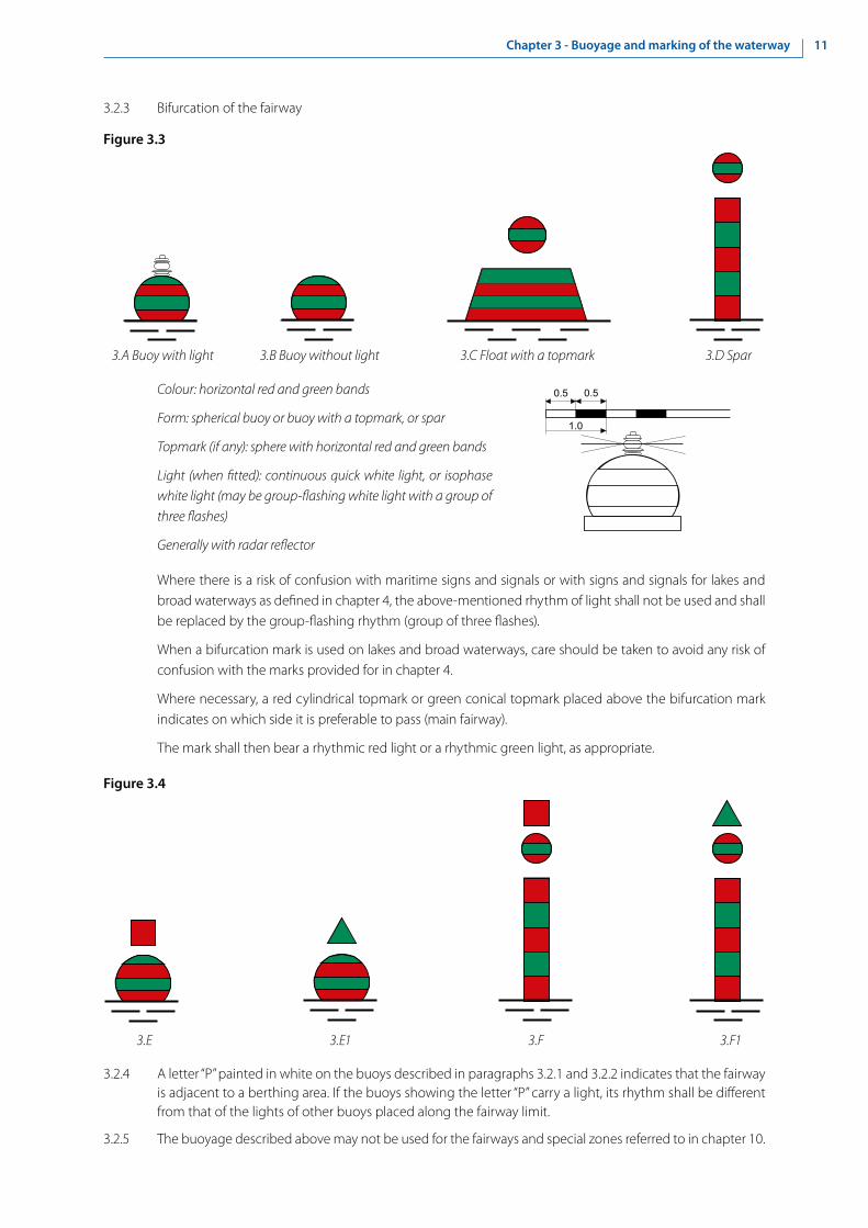
3.2.3 Bifurcation of the fairway
Figure 3.3
3.A Buoy with light 3.B Buoy without light 3.C Float with a topmark 3.D Spar
Colour: horizontal red and green bands
Form: spherical buoy or buoy with a topmark, or spar
Topmark (if any): sphere with horizontal red and green bands
Light (when fitted): continuous quick white light, or isophase white light (may be group-flashing white light with a group of three flashes)
Generally with radar reflector
Where there is a risk of confusion with maritime signs and signals or with signs and signals for lakes and broad waterways as defined in chapter 4, the above-mentioned rhythm of light shall not be used and shall be replaced by the group-flashing rhythm (group of three flashes).
When a bifurcation mark is used on lakes and broad waterways, care should be taken to avoid any risk of confusion with the marks provided for in chapter 4.
Where necessary, a red cylindrical topmark or green conical topmark placed above the bifurcation mark indicates on which side it is preferable to pass (main fairway).
The mark shall then bear a rhythmic red light or a rhythmic green light, as appropriate.
Figure 3.4
3.E 3.E1 3.F 3.F1
3.2.4 A letter “P” painted in white on the buoys described in paragraphs 3.2.1 and 3.2.2 indicates that the fairway is adjacent to a berthing area. If the buoys showing the letter “P” carry a light, its rhythm shall be different from that of the lights of other buoys placed along the fairway limit.
3.2.5 The buoyage described above may not be used for the fairways and special zones referred to in chapter 10.

12 Chapter 3 - Buoyage and marking of the waterway
3.3 Buoyage and marking of danger points and obstacles
3.3.1 Where it is desired merely to draw attention to an obstacle or danger point without requiring vessels under way to move in a particular direction, the following may be used:
(a) For obstacles and danger points in the fairway: the buoys, spars, topmarks and lights prescribed in section 3.2 for marking the fairway limits.
(b) For obstacles and danger points outside the fairway: either fixed marks (see 3.3.2) or buoys (see 3.3.4) in the waterway.
3.3.2 Fixed marks are indicated below.
(a) Right-hand side
Figure 3.5
Colour: red
Form: post with topmark
Topmark: red cone, point downwards
Light (when fitted): rhythmic red light
(b) Left-hand side
Figure 3.6
Colour: green
Form: post with topmark
Topmark: green cone, point upwards
Light (when fitted): rhythmic green light
(c) Bifurcation
Figure 3.7
Colour: red/green
Form: post with topmark
Topmark: red cone, point downwards, above a green cone, point upwards
Light (when fitted): continuous quick white light or isophase white light (may be the group-flashing white light a group of three flashes)
The above cones may be replaced by triangular panels with a white background and a red or green border.
4.F
5.F
6.A 6.B

13Chapter 3 - Buoyage and marking of the waterway
3.3.3 Secondary arms of the waterway, mouths of waterways and entrances to harbours
On the approach to secondary arms of the waterway, to mouths of waterways and to harbour entrances, the bank walls on both sides of the waterway may be marked as far as the head of the dividing mole by the fixed marks described in 3.3.2, (a) and (b). Vessels entering the harbour are regarded as upstream traffic.
3.3.4 Buoys are described below:
(a) Right-hand side
Figure 3.8
Colour: horizontal red and white bands
Form: spar-buoy or spar
Topmark: red cylinder
Light (when fitted): rhythmic red lightGenerally with radar reflector
(b) Left-hand side
Figure 3.9
Colour: horizontal green and white bands
Form: spar-buoy or spar
Topmark: green cone, point upwards
Light (when fitted): rhythmic green light
Generally with radar reflector
1.F1 1.F
2.F1 2.F

14 Chapter 3 - Buoyage and marking of the waterway
3.3.5 Examples of using the signs in paragraphs 3.3.2-3.3.4 are given in figures 3.10 and 3.11.
Figure 3.10 B
y ni
ght
(fig. 11)
By night

15Chapter 3 - Buoyage and marking of the waterway
Figure 3.11
By day
16 Chapter 3 - Buoyage and marking of the waterway
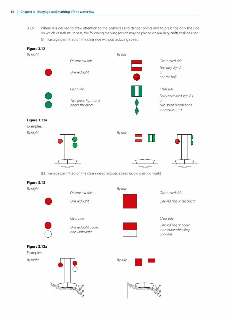
3.3.6 Where it is desired to draw attention to the obstacles and danger points and to prescribe only the side on which vessels must pass, the following marking (which may be placed on auxiliary craft) shall be used:
(a) Passage permitted on the clear side without reducing speed
Figure 3.12
Figure 3.12a
Examples:
Obstructed side Obstructed side
One red lightNo entry sign A.1,orone red ball
Clear side Clear side
Two green lights one above the other
Entry permitted sign E.1,ortwo green bicones one above the other
Obstructed side Obstructed side
One red light One red �ag or red board
Clear side Clear side
One red light above one white light
One red �ag or board above one white �ag or board
(b) Passage permitted on the clear side at reduced speed (avoid creating wash)
Figure 3.13
Figure 3.13a
Examples:
By night By day
By night By day
By night By day
By night By day

17Chapter 3 - Buoyage and marking of the waterway
3.3.7 Where it is desired both to draw attention to such obstacles and danger points and to require vessels under way to reduce speed in order to avoid causing wash, the flags, boards, balls or lights shown below shall be used; they may be placed whether on the obstacle itself or on an auxiliary craft.
3.4 Bank marks indicating the position of the fairway
3.4.1 Bank marks indicating the position of the fairway in relation to the banks
These signs indicate the position of the fairway in relation to the bank and, together with the buoyage of the waterway, mark the fairway at points where it approaches a bank; they also serve as landmarks.
(a) Fairway near the right bank
Figure 3.14
4.A With light 4.B Without light
Colour: red/white
Form: post with topmark
Topmark: square boards (sides horizontal and vertical), red, with two horizontal white stripes
Light (when fitted): rhythmic red light
(b) Fairway near the left bank
Figure 3.15
5.A With light 5.B Without light
Colour: green/white
Form: post with topmark
Topmarks: square board (diagonals horizontal and vertical), upper half painted green and lower half white
Light (when fitted): rhythmic green light

18 Chapter 3 - Buoyage and marking of the waterway
3.4.2 Marking of cross-overs
Marking of cross-overs indicate at what point the fairway passes from one bank to another and also give the axis of this cross-over:
(a) Right bank
Figure 3.16
4.C With light 4.D Without light
Colour: yellow/black
Form: post with topmark
Topmarks: square yellow board (sides horizontal and vertical), with a central vertical black stripe
Light (when fitted): yellow light, flashing or occulting, with an even-number characteristic other than the group-flashing rhythm with a group of two flashes
(b) Left bank
Figure 3.17
5.C With light 5.D Without light
Colour: yellow/black
Form: post with topmark
Topmark: square yellow board (diagonals horizontal and vertical), with a central vertical black stripe
Light (when fitted): yellow light, flashing or occulting, with an odd-number characteristic other than the group-flashing rhythm with a group of three flashes
3.5 Buoyage and marking of lakes and broad waterways
Main navigation signs
3.5.1 The main navigation signs are given in annex 7 to CEVNI. The signs with their minimal dimensions are given in appendix 1.

19Chapter 3 - Buoyage and marking of the waterway
Auxiliary navigation signs
3.5.2 The main signs may be supplemented by the following auxiliary signs:
(a) Panels showing the distance at which the regulation applies or the special feature indicated by the main sign is to be found
The panels are placed above the main sign.
Figure 3.18
Examples:
In 1,000 m, stop In 1,500 m, ferry-boat not moving independently
(b) Additional luminous signal
Additional luminous signals are given in section 4.4.
(c) Pointers showing the direction of the section to which the main sign applies
Note: The pointers need not necessarily be white and may be placed beside or below the main sign.
Figure 3.19
Examples:
Berthing permitted
Berthing prohibited (over a distance of 1,000 m)

20 Chapter 3 - Buoyage and marking of the waterway
Figure 3.20
Examples:
Stop for Customs Give one long blast
(e) Panels indicating the type of craft concerned
Where a prohibition, a mandatory requirement or an indication applies only to a particular type of craft or activity, the symbol for such craft or activity shall be shown in black on a white ground on a panel below the sign.
Figure 3.21
Example: Mandatory requirement for motorized craft to take a speci�ed direction
(d) Panels giving explanations or additional information
Note: These panels are placed below the main sign.

21Chapter 3 - Buoyage and marking of the waterway
3.6.2 Pole with radar reflector is placed upstream and downstream from bridge piers.
Figure 3.23
8.C 8.C1
8.C2
3.6 Additional marking for navigation by radar
3.6.1 Yellow floats with radar reflectors are placed upstream and downstream from piers.
Figure 3.22
3.7 Buoys for miscellaneous purposes
3.7.1 Buoys required for purposes other than those referred to above shall be predominantly white, to avoid confusion with red, green or yellow buoys. They may carry pictograms.
3.8 Warning posts
3.8.1 In special cases where it is necessary to set up warning posts (e.g. on winding sections of waterway where the visual range is limited), the competent authorities shall determine the signals to be given by such posts so far as possible on the basis of the present SIGNI, and in such a way as to avoid confusion or conflict with the signals described in them.

23Chapter 4 - Buoyage and marking of lakes and broad waterways
Chapter 4 - Buoyage and marking of lakes and broad waterways
4.1 General
4.1.1 Subject to the exception referred to in 3.2.3, the provisions of sections 3.2 to 3.4 shall apply to lakes and broad waterways. However, additional marks, taken from the IALA Aids to Navigation system may be used, if required:
• marking of danger points, obstacles and special features: cardinal marks, isolated danger marks, marking of new dangers;
• safe water marks;
• special marks for marking of prohibited or restricted zones;
• weather signs and signals on lakes.
4.1.2 In addition, danger points, obstacles and special features may be marked by other electronic means, such as automatic identification system (AIS).
4.1.3 If the competent authorities consider the risk to navigation to be especially high, at least one of the marks should be duplicated. Any duplicate mark shall be identical to its partner in all respects.
4.2 Marking of danger points, obstacles and special features
4.2.1 Cardinal marks
The four quadrants (North, East, South and West) are bounded by the true bearings NW-NE, NE-SE, SE-SW, SW-NW taken from the point of interest.
A cardinal mark is named after the quadrant in which it is placed.
The name of a cardinal mark indicates that the mark should be passed on the side of the quadrant named.
A cardinal mark may be used for example:
• to indicate that the deepest water in that area is on the named side of the mark;
• to indicate the safe side on which to pass a danger;
• to draw attention to a particular feature in a fairway such as a bend, a junction, a bifurcation or the extremity of a shoal.

24 Chapter 4 - Buoyage and marking of lakes and broad waterways
Figure 4.1
North cardinal mark
Topmark: two black cones, one above the other, points upwardColour: black above yellowForm: pillar or spar, with topmarkLight (when �tted):
Colour: whiteRhythm: continuous very quick or continuous quick
East cardinal mark
Topmark: two black cones, one above the other, base to baseColour: black with a single broad horizontal yellow bandForm: pillar or spar, with topmarkLight (when �tted):
Colour: whiteRhythm: group very quick or group quick, with a group of three �ashes
West cardinal mark
Topmark: two black cones, one above the other, point to pointColour: yellow with a single broad horizontal black bandForm: pillar or spar, with topmarkLight (when �tted):
Colour: whiteRhythm: group very quick or group quick, with a group of nine �ashes
South cardinal mark
Topmark: two black cones, one above the other, points downwardColour: yellow above blackForm: pillar or spar, with topmarkLight (when �tted):
Colour: whiteRhythm: group very quick or group quick, with a group of six �ashes followed by a long �ash of not less than two seconds duration
25Chapter 4 - Buoyage and marking of lakes and broad waterways
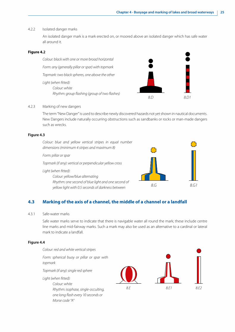
4.2.2 Isolated danger marks
An isolated danger mark is a mark erected on, or moored above an isolated danger which has safe water all around it.
Figure 4.2
Colour: black with one or more broad horizontal
Form: any (generally pillar or spar) with topmark
Topmark: two black spheres, one above the other
Light (when fitted):Colour: whiteRhythm: group flashing (group of two flashes)
4.2.3 Marking of new dangers
The term “New Danger” is used to describe newly discovered hazards not yet shown in nautical documents. New Dangers include naturally occurring obstructions such as sandbanks or rocks or man-made dangers such as wrecks.
Figure 4.3
Colour: blue and yellow vertical stripes in equal number dimensions (minimum 4 stripes and maximum 8)
Form: pillar or spar
Topmark (if any): vertical or perpendicular yellow cross
Light (when fitted):Colour: yellow/blue alternatingRhythm: one second of blue light and one second of yellow light with 0.5 seconds of darkness between
4.3 Marking of the axis of a channel, the middle of a channel or a landfall
4.3.1 Safe-water marks
Safe water marks serve to indicate that there is navigable water all round the mark; these include centre line marks and mid-fairway marks. Such a mark may also be used as an alternative to a cardinal or lateral mark to indicate a landfall.
Figure 4.4
Colour: red and white vertical stripes
Form: spherical buoy or pillar or spar with topmark
Topmark (if any): single red sphere
Light (when fitted):Colour: whiteRhythm: isophase, single-occulting, one long flash every 10 seconds or Morse code “A”
8.D18.D
8.G18.G
8.E28.E18.E

26 Chapter 4 - Buoyage and marking of lakes and broad waterways
4.4 Special marks
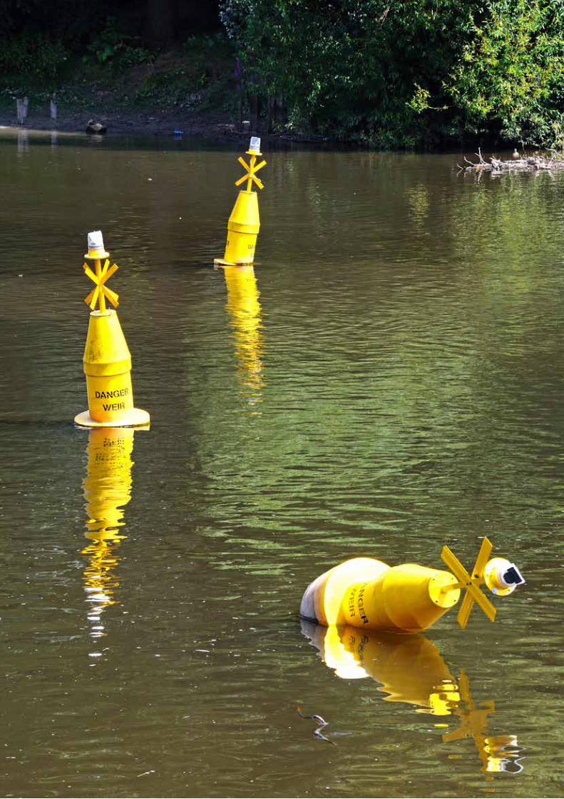
Marks not primarily intended to assist navigation but which indicate a special area or feature referred to in appropriate documents, such as military exercise zone marks, recreation zone marks.
Figure 4.5
Colour: yellow
Shape: optional, but not conflicting with navigational marks
Topmark, if any: single yellow, “X” shape
Light (when fitted):Colour: yellowRhythm: any, other than those described in 4.2, 4.3 and 4.5
4.5 Weather signs and signals on lakes
4.5.1 “Caution” warning
A yellow light producing about 40 flashes per minute constitutes a “caution” warning.
The “caution” warning indicates the probable onset of a dangerous phenomenon without specifying the time thereof.
4.5.2 “Imminent danger” warning
A yellow light producing about 90 flashes per minute constitutes a “danger” warning.
The danger warning indicates the imminent arrival of a dangerous phenomenon.
4.6 Example of signs and signals on lakes and broad waterways
Figure 4.6 illustrates the provisions of this section for lakes and broad waterways.
8.F18.F
SHAPE OPTIONALUSE OF PICTOGRAMS
AUTHORISED

27Chapter 4 - Buoyage and marking of lakes and broad waterways
Figure 4.6


29Chapter 5 - Lights
Chapter 5 - Lights
5.1 Definitions
5.1.1 The terms “white light”, “red light”, “green light”, “yellow light” and “blue light” mean lights of colours according to the provisions referred to in appendix 2.
5.1.2 The terms “quick light” and “very quick light” mean rhythmic lights at a rate of 50-80 flashes per minute and 80-160 flashes per minute.
5.2 Fixed lights
5.2.1 The basic principle of marking by fixed lights is as follows:
• A fixed red light means “Stop”;
• A fixed green light means “Go ahead”.
The meaning of the other marks comprising red or green lights derives from that principle. In particular, a fixed red light combined with other lights means either “Stop” or “Caution”.
However, since green lights are always placed at the side of the waterway or fairway, vessels must never steer towards a green light. It has therefore been found necessary to provide for another signal authorizing passage towards which vessels may steer: a yellow light.
Pairs of lights should form a visual angle of not less than 5’ (tan 5’ = 0.00145) to distinguish them from one another.
5.2.2 The meaning of the signals given by fixed lights is given in table 5.1.
Table 5.1
Numbering Signal Description MeaningА. Prohibitory signs
А.1с Single red light “No passage”
In cases where a single red light is not sufficient to clearly indicate the intended prohibition, the use of two or more red lights is recommended
А.1b Two red lights placed one above the other (a pair)
A.1d Two red lights placed side by side (a pair)
A.11c Extinction of one of the red lights means: “Passage forbidden (passage about to be authorized)”
A.9b A red light above a white light
“Do not cause wash”
A.11a
or
A red light and a green light placed side by side (a pair) or a red light above a green light
“No passage now but stand by to go ahead”. This signal is always operable as required
A.11b

30 Chapter 5 - Lights
Numbering Signal Description MeaningB. Mandatory signs
B.10 Two isophase yellow lights placed one above the other (a pair)
Vessels proceeding on the main waterway must, if necessary, change course and speed to allow vessels to leave harbours or tributary waterways
D. Recommendatory signs
D.2b Two green lights set apart
“Go ahead between the lights”
D.1b Single yellow light Recommended opening in both directions. “Go ahead, but look out for traffic coming the other way”. Vessels may steer towards the yellow light, which is placed above the navigable fairway
D.1f
or
A pair of yellow lights (placed one above the other, or, if necessary, side by side), alone or between green lights
Recommended opening only in the direction indicated. “Go ahead; traffic in the opposite direction is prohibited”. Vessels may steer towards the yellow lights, which are placed above the fairway
D.1e
D.3b A fixed white light and an isophase white light placed side by side (a pair)
“You are recommended to steer in the direction from the fixed light towards the isophase light”. Signal to be used, for example, on the approach to a double lock
E. Informative signs
E.1b Single green light “Go ahead” (the green light is always placed at the side of the fairway). In cases where a single green light is not sufficient to clearly indicate the allowed passage, the use of two green lights is recommended
E.1c Two green lights placed side by side (a pair)
E.1d Two green lights placed one above the other (a pair)
Е.12 One or two white lights “Difficulty ahead — Stop if the regulations so require”
E.12a
or
Fixed light(s): advance signal
Examples: Lock closed, vessel navigating in the opposite direction
E.12b
E.12c
or
Isophase light(s): advance signal “You may proceed”
Examples: Lock open, no vessel navigating in the opposite direction
E.12d
Notes: Each fixed red, green or yellow light may be replaced by a red-white-red, a green-white-green or a yellow board respectively, as provided below in chapters 8 and 9.
Single fixed white lights shall not be used except as advance signals. Fixed white lights must be used with care as they may be confused with other white lights (for instance, public lighting).

31Chapter 5 - Lights
5.3 Rhythmic lights
Rhythmic lights are described in sections 3.2-3.4, chapter 4 and appendix 4.
5.4 Additional luminous signal
Additional luminous signal is a luminous white arrow combined with certain lights from section 5.2. The signal relates to the direction of navigation shown by the arrow.
Figure 5.1
Examples: On a main waterway, at the entrance to a basin, this signal means:
(a) With green light
Figure 5.2
Permission to enter the basin to which the arrow is pointing
(b) With red light
Figure 5.3
No entry to the basin to which the arrow is pointing
5.5 Semaphores
5.5.1 In special cases where a semaphore is required to regulate navigation (e.g. in harbours), the competent authorities shall determine the signals to be given by the semaphore in such a way as to avoid any confusion or conflict with the signals described in the present provisions.
5.5.2 The competent authorities shall preferably choose a signalling system using red and green lights, operable as required.


33Chapter 6 – Installation of signs and marking in characteristic sections of the river
Chapter 6 - Installation of signs and marking in characteristic sections of the river
6.1 General
6.1.1 Signs have two possible orientations, namely:
(a) Parallel to the axis of the fairway;
(b) Perpendicular to the axis of the fairway.
6.1.2 Signs of the type mentioned under 6.1.1 (a), are predominantly prohibitory or indicative signs, and are placed on the side of the fairway to which the prohibition or the indication applies.
Bank marks which are used in relation to navigation in both directions (upstream and downstream) shall be oriented as under 6.1.1 (a). In some cases, (better visibility) the angle between the mark and the axis of the fairway can be 10° or less (figure 6.1, sign a).
Figure 6.1
60-90°
cb
a
0-10°0-10°
6.1.3 Most signs are positioned as described under 6.1.1 (b), and generally do not apply to one side of the fairway only. These signs are erected at right angles to the axis of the fairway so that they are visible to a user when under way.
Bank marks which are used in relation to navigation in one direction (upstream or downstream) shall be oriented as under 6.1.1 (b). In some cases, (better visibility) the angle between the mark and the axis of the fairway cannot be less than 60° (figure 6.1, sign c).
6.1.4 The use of a particular floating sign or bank mark and how it is installed depends on the one hand on the local features of the river (speed of current, variation in levels, meanders, width of the river bed, existence of sills, branches, islands, etc.), and on the other hand on the density of traffic in a given sector and the form and size of convoys.
6.1.5 The position of each floating sign indicating the side of the fairway shall be determined on the basis of the marking plan based on the results of measurements. Depths within the limits of the width of the marked fairway shall under no circumstances be less than the minimum depth reported for the sector in question.
6.1.6 When floating signs are installed, it is essential to take the direction of the current into account. If the current flows in the direction of a navigational hazard (obstacle), the sign or signal shall always be placed a long way from it; if, on the other hand, it flows in the opposite direction, the sign or signal shall be placed nearer.
6.1.7 An example of the installation of the marks indicating the position of the fairway is given in figure 6.2.

34 Chapter 6 – Installation of signs and marking in characteristic sections of the river
Figure 6.2
6.1.8 Obstacles on the sides of the fairway are always marked with floating signs. When the obstacle is indicated by a single sign, it shall be placed on the upstream extremity of the obstacle, on the fairway side (figure 6.1, sign b).
6.1.9 As a rule, lighted buoys or unlighted buoys shall be used to mark the upstream and downstream extremities of sills, banks which narrow the fairway in meandering sectors, banks protruding into the fairway, piles of stones, reefs, water supply engineering structures, and underwater hazards or obstacles (sunken vessels, anchors, etc.).
6.1.10 Marker posts and spars shall be used as additional signs supplementing buoys in order to give a clearer indication of the limits of the fairway over difficult sills and in order to mark underwater obstacles. In some cases and in some sectors, buoys may be replaced by marker posts or spars.
6.1.11 In order to avoid damage to buoys during the period when ice is carried down, they shall be replaced by spars or marker posts.
6.1.12 On sectors of the river where there is day and night navigation, forks, junctions and the axis of the fairway, along with obstacles to navigation lying within the fairway, shall be marked by light buoys or bank marks and lights. Floating signs shall be installed at such a depth and at such a distance from the obstacle that the safety and ease of movement of vessels shall be guaranteed at night and in poor visibility.
6.1.13 On sectors where the river bed is narrow, preference shall be given to bank marks.
6.1.14 Each bank mark shall be established following reconnaissance of the area and selection of the most appropriate site. The need to ensure the visibility of the sign whatever the level of the water should be taken into consideration.
6.1.15 Where it is necessary to ensure good visibility of the symbol on the sign over a long distance, both for vessels proceeding upstream and vessels proceeding downstream, two boards may be installed on the sign pole at an angle to each other, one pointing upstream and the other downstream.
6.1.16 In selecting the site of bank mark, account shall be taken of the need to ensure easy maintenance and to protect it against ice and flooding.
6.1.17 Before a bank sign or signal is installed, the depth in the area in front of it and in the direction it indicates shall always be measured.
6.1.18 As a general rule, the objective is that only the network of bank marks shall provide an uninterrupted indication of the position of the fairway as a whole, while the floating signs shall help boatmasters to determine the limits of the fairway.
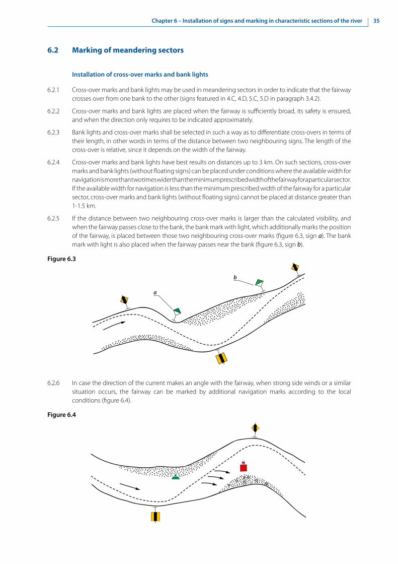
35Chapter 6 – Installation of signs and marking in characteristic sections of the river
b
a
6.2 Marking of meandering sectors
Installation of cross-over marks and bank lights
6.2.1 Cross-over marks and bank lights may be used in meandering sectors in order to indicate that the fairway crosses over from one bank to the other (signs featured in 4.C, 4.D, 5.C, 5.D in paragraph 3.4.2).
6.2.2 Cross-over marks and bank lights are placed when the fairway is sufficiently broad, its safety is ensured, and when the direction only requires to be indicated approximately.
6.2.3 Bank lights and cross-over marks shall be selected in such a way as to differentiate cross-overs in terms of their length, in other words in terms of the distance between two neighbouring signs. The length of the cross-over is relative, since it depends on the width of the fairway.
6.2.4 Cross-over marks and bank lights have best results on distances up to 3 km. On such sections, cross-over marks and bank lights (without floating signs) can be placed under conditions where the available width for navigation is more than two times wider than the minimum prescribed width of the fairway for a particular sector. If the available width for navigation is less than the minimum prescribed width of the fairway for a particular sector, cross-over marks and bank lights (without floating signs) cannot be placed at distance greater than 1-1.5 km.
6.2.5 If the distance between two neighbouring cross-over marks is larger than the calculated visibility, and when the fairway passes close to the bank, the bank mark with light, which additionally marks the position of the fairway, is placed between those two neighbouring cross-over marks (figure 6.3, sign a). The bank mark with light is also placed when the fairway passes near the bank (figure 6.3, sign b).
Figure 6.3
6.2.6 In case the direction of the current makes an angle with the fairway, when strong side winds or a similar situation occurs, the fairway can be marked by additional navigation marks according to the local conditions (figure 6.4).
Figure 6.4

36 Chapter 6 – Installation of signs and marking in characteristic sections of the river
6.2.7 When the fairway follows the middle of the river bed over a long distance or when it crosses abruptly from one bank to the other, its axis may be indicated by a pair of cross-over marks on each side of the fairway, as shown in figure 6.5.
The advantage is given to two cross-over marks on each side of the fairway in case of straight-line sections longer than 5 km, where the available width for navigation is less than double the width of the minimum prescribed width of the fairway for a particular sector. In that case and when the bank configuration allows so, the cross-over marks are placed on both margins of the transition (figure 6.5).
It is always preferable to have two cross-over marks on each side of the fairway when the fairway is narrowed by certain obstacles constituting threats to navigation or other hazards marked by floating signs.
Figure 6.5
b
d > 5 km
b less than double width of the fairway
6.2.8 In sectors where the fairway, after moving to the opposite bank, abruptly crosses to the other bank, three cross-over marks (the front shall have two boards) must be placed (figure 6.6). In this case, lights of the back cross-over marks shall be oriented strictly on the axis of the fairway, one upstream and the other downstream.
Figure 6.6

37Chapter 6 – Installation of signs and marking in characteristic sections of the river
6.2.9 Interrelationships of the front and back marks at hidden routes shorter than 4 km are presented in table 6.1.
Table 6.1
L (m) d (m) ho (m) a (m) 2a (m)200 17 8.50 2.6 5.0300 25 8.70 4.0 8.0400 33 8.85 5.2 10.5500 42 9.00 6.5 13.0600 50 9.10 8.0 16.0700 58 9.20 9.0 18.0800 67 9.35 10.0 20.0900 75 9.50 12.0 24.0
1 000 83 9.60 13.0 26.01 500 125 10.25 19.0 38.02 000 166 10.90 26.0 52.02 500 207 11.50 33.0 66.03 000 250 12.15 39.0 78.03 500 290 12.75 46.0 92.04 000 330 13.40 52.0 104.0
> 4 000 760 14.20 25.0 50.0
Where (see figure 6.7):
L (m) — maximal distance when cross-over marks can be used;
d (m) — distance between front and back signs (is approximately 1/12 L);
h0 (m) — height between lights of front and back mark;
a (m) — distance necessary for a vessel to adjust its course if the vessel does not go along the cross-over;
α (‘) — viewing angle.
Table 6.1 also assumes that the observer’s sight is 5 m above the water level, and the light of the lower (front) sign is 8 m above the water level.
Figure 6.7
d
xh
L
αo
o
Value α describes accuracy of the route and it is of significance while navigating through a narrow fairway. Accuracy is, in principle, increased by approaching the cross-over marks.
To ensure proper recognition of cross-over marks and their lights, the viewing angle cannot be less than 4 angular minutes in relation to the vertical.

38 Chapter 6 – Installation of signs and marking in characteristic sections of the river
Installation of floating signs
6.2.10 In meandering sectors, where the fairway passes along the middle of the river bed, or along the bank or passes slowly from one bank to the other, floating signs are used to mark formations in the river bed or obstacles, both natural and artificial, on the sides of the fairway (banks, shores, islands, stones, sunken vessels, wrecks of bridges, etc.), when these obstacles protrude into the fairway and reduce its width (figure 6.8).
These underwater obstacles are marked in meandering sectors by floating signs if, within the limits of width indicated above, the depth of water over such obstacles does not exceed the minimum depth reported for the sector. If the obstacle is not very wide, a floating sign with light shall be installed on its upstream section. A marker post or a spar may be installed on its downstream section, depending on its length.
Figure 6.8
b b1
b < double width of the fairway b1 > double width of the fairway
6.2.11 Floating signs marking underwater obstacles of considerable length are installed in such a way that the parts situated closest to the fairway are marked by light signals between which unlighted signs are placed, thus enabling a given obstacle to be marked completely (figure 6.9).
Figure 6.9
6.2.12 In the parts of the river bed where the shore opposite that followed by the fairway is bordered by an inshore bank which favours upstream navigation in calm water, the bank is marked by floating signs independently of the width of the river bed.
6.2.13 In meandering sectors the bank marking system in periods of high water generally remains the same as in periods of lowest water level, except in sectors where, when water levels are high, it is advisable to find another fairway with better navigational features. In this case, the selected fairway shall be marked appropriately.

39Chapter 6 – Installation of signs and marking in characteristic sections of the river
6.3 Marking of shoals
6.3.1 In shoals, as in other sections, the principle of the continuous marking of the direction of the fairway shall be applied.
In shoals the fairway can be marked by cross-over marks, bank marks and floating signs.
6.3.2 Alternately located shoals may also be marked by cross-over marks, with sufficient available width for navigation in which vessels are passing in a straight line (figure 6.10).
Figure 6.10
6.3.3 A fairway passing over shoals is usually marked by floating signs (figures 6.10 and 6.11).
Figure 6.11
6.3.4 If the fairway passes in a straight line between sandbars, reaching far into the river bed, it is necessary to place at least two floating signs at the entry and the exit of such a section: one at the top of the upstream and one on the top of the downstream sandbar (figure 6.12).
Figure 6.12

40 Chapter 6 – Installation of signs and marking in characteristic sections of the river
6.3.5 If the fairway is curved in the section between sandbars, it is necessary to place additional floating signs (figure 6.13).
Figure 6.13
6.3.6 Additional floating signs shall also be placed on the entry and exit of rugged sections with sandbars, which also characterize the side streams.
6.3.7 In case the application of cross-over marks is impossible, the fairway across a shoal may be marked only by floating signs, on one or both sides, depending on the width of the fairway and hydrological conditions.
6.4 Marking of the vicinity of bridges and passages through bridges
6.4.1 The navigation of vessels and convoys in the vicinity of bridges and through bridge passages requires particular attention and precautions on the part of boatmasters because of the narrow fairway. These sections must therefore be marked with the greatest care.
6.4.2 The basic condition to be met to ensure safe passage through bridges is the marking of the direction of the fairway and also, where necessary, its sides. Floating signs and bank marks may be used in addition to boards and lights for marking the navigable passage through bridges.
6.4.3 The choice and positioning of the marking signs depends in each case on local conditions in the bridge section.
6.4.4 The installation of marking signs in the vicinity of bridges and the buoying of navigable passages shall comply with the following conditions:
(a) In order to indicate permission to use the navigable passage of a bridge, only signs A.10, D.1 or D.2 from annex 7 to CEVNI shall be used;
(b) The installation of marking signs shall be based on depth and current direction measurements, both in the immediate vicinity of the bridge and in the approach sections;
(c) The positioning of the signs installed in the vicinity of a bridge shall be modified in due course, as conditions of navigation change;
(d) If, when approaching the bridge or the navigable passage, the direction of the current forms an angle with the bridge, giving rise to eddies around the pillars of the bridge, the floating signs shall be so installed as to indicate the direction of the eddies.
6.4.5 Floating signs may be installed at the approach to the navigable passage to give an exact indication of the position of the fairway.

41Chapter 6 – Installation of signs and marking in characteristic sections of the river
6.4.6 The following examples show the placement of the aforementioned signs marking the section near bridges:
(a) If a bridge is in a meandering section of the river, the direction of vessels passing through the bridge passages may be marked by bank marks (figure 6.14);
Figure 6.14
Axis of the fairway
100100 - 200400 - 700
(b) If, due to a larger curvature of the fairway or for some other reasons, marking by the aforementioned signs is not possible, floating signs (buoys, etc.), placed in order to follow the river flow, may be used (figure 6.15);
Figure 6.15
(c) If the bridge is positioned on the section where the current makes an angle with the axis of the navigable passage, marking may be done by two pairs of buoys upstream of the bridge. One pair of buoys is placed at a distance of 100 m-200 m upstream of the bridge, and a second pair, 400 m-700 m upstream of the bridge. Buoys further away from the bridge are placed in such a way that, in combination with the pair of buoys closer to the bridge, they mark the river flow. Another pair of buoys may be placed downstream of the bridge at a distance of 100 m from the bridge (figure 6.16).
Figure 6.16

42 Chapter 6 – Installation of signs and marking in characteristic sections of the river
6.5 Installation of floating signs restricting berthing points
6.5.1 Where there is increased intensity of vessels’ traffic and the substantial accumulation of vessels in inner harbour basins of ports, not only bank marks should be used in order to restrict berthing places but also floating signs.
6.6 Reference numbers on buoys and marker posts
6.6.1 On buoys and marker posts the use of alphanumeric characters and capital letters is recommended. Where both letters and figures are used, their heights should be the same. Where two such combinations occur, as on junction markers, a hyphen should be used.
6.6.2 Characters should not be less than 200 mm high, white on red or green buoys, or black on yellow buoys.
6.6.3 The characters on a lighted buoy can be black on a white background. Signs are usually affixed to special nameplates. It is recommended that the characters be displayed on both sides of buoys.


45Chapter 7 – Marking of harbour entrances
Chapter 7 - Marking of harbour entrances
7.1 In this chapter, the expression “entrances to harbours” also includes entrances to tributary waterways, entrances to secondary arms of waterways and entrances to docks.
7.2 If day marking at the harbour entrance is necessary, the entrance shall be marked:
• To port of a vessel entering: by painting the light pillar, preferably cylindrical, red; or by means of a cylindrical red topmark; or by painting red rectangles on the jetty;
• To starboard of a vessel entering: by painting the light pillar, preferably conical, green; or by means of a conical green topmark; or by painting green triangles, point upwards, on the jetty.
7.3 At night, for small harbours, it shall be sufficient to illuminate the day markings described above. If lights are considered necessary, the entrance shall be marked:
• To port of a vessel entering: by a red light, preferably rhythmic;
• To starboard of a vessel entering: by a green light, preferably rhythmic.
In the case of a narrow or specially shaped entrance, one of these lights may be sufficient to help a boatmaster to enter the harbour. Such a single light shall be rhythmic.
Figure 4.6 illustrates the provisions of this section for lakes and broad waterways.
7.4 The same rules shall apply to the colours and shapes of buoys and marks on fairways leading into the harbour.
It is recommended that lights of the same colour used for signalling the entrance to the harbour and buoying the fairway should have different rhythms to permit differentiation.
The installation of the above lights for marking the entrance to the harbour does not preclude the installation of fixed lights having the meaning attached to them in chapter 5, with a view to regulating navigation. In such cases, the lights marking the entrance to the harbour shall be rhythmic.


47Chapter 8 – Marking of permanent structures
Chapter 8 - Marking of permanent structures
8.1 General principle
8.1.1 The marks indicated in figures 8.1 or 8.2 may be used to mark the width of the fairway in openings of bridges and through weirs by showing the site of the piers, or if appropriate, to show the boundaries between which the fairway is normally usable (e.g. where the depth of water or headroom near the piers is insufficient).
Figure 8.1
A.10 Navigation is prohibited outside the area between the two boards constituting the sign
Figure 8.2
D.2a
or
You are recommended to keep within the area the two boards constituting the sign
D.2b
For the convenience of boatmasters, inverted scales showing the headroom available under the bridge may be affixed to the piers.
8.1.2 The following may be replaced for fixed bridges, weirs and locks:
Each fixed red light by a rectangular red board with a horizontal white bar; and
Each fixed green light by a rectangular green board with a vertical white bar
For fixed bridges, the following may be replaced:
Each fixed yellow light by a square yellow board with the diagonals horizontal and vertical

48 Chapter 8 – Marking of permanent structures
8.2 Fixed bridges
8.2.1 Entry prohibited
Figure 8.3
A.1a A.1b
A.1c A.1d
D.1a D.1b
D.1c D.1d
D.1e D.1f
8.2.2 Opening recommended for entry (preferable)
(a) In both directions
Figure 8.4
(b) Only in the direction indicated (passage in the opposite direction prohibited, the entrance of the other side is marked with sign A.1 (see 8.2.1))
Figure 8.5
8.2.3 Fairway not expressly recommended
When certain openings in fixed bridges are marked as specified in 8.2.2 and others bear no marks, the boatmaster may use the unmarked openings only at his own risk.

49Chapter 8 – Marking of permanent structures
8.3 Movable bridges
8.3.1 Passage prohibited
(a) General prohibition
Figure 8.6
(b) Passage prohibited except for vessels of reduced height; passage authorized in both directions
Figure 8.7
(c) Passage prohibited except for vessels of reduced height; passage prohibited in the opposite direction
Figure 8.8
(d) Passage is still prohibited, but the bridge is being opened and the boatmaster should prepare to get under way
Figure 8.9
(e) The opening of the bridge for navigation is suspended
Figure 8.10

50 Chapter 8 – Marking of permanent structures
8.3.2 Passage permitted
Figure 8.11
8.4 Weirs
8.4.1 Passage through an opening in a weir is prohibited
Prohibition of passage through an opening in a weir may be indicated by one or more red lights or red-white-red boards (sign A.1) as shown in figure 8.3.
8.4.2 Passage through an opening in a weir is permitted
(a) As a general rule
Figure 8.12
(b) In case of weirs with an overhead bridge
Figure 8.13
E.1a E.1b
E.1c E.1d
D.1a D.1b

51Chapter 8 – Marking of permanent structures
8.5 Locks, ship lifts and inclined planes
8.5.1 Entry or exit prohibited
(a) No entry, lock out of service
Figure 8.14
(b) No entry or exit, lock is closed
Figure 8.15
(c) No entry, lock is being prepared for opening
Figure 8.16
8.5.2 Entry or exit permitted
Figure 8.17
8.5.3 In the absence of lights and boards, it is prohibited to enter and leave locks except by express order of the lock staff.
8.5.4 The provisions of 8.5 also apply to other types of crossings such as ship lifts and inclined planes.


53Chapter 9 – Blockage of the waterway
Chapter 9 - Blockage of the waterway
9.1 Suspension of navigation for all vessels
A.1a In general
А.1b In general
А.1d
А.1с A single red light may be used if it is sufficient clearly to indicate the prohibition and cannot be confused with lights extraneous to the waterway marking lights
A.1f orA.1e
In case of emergency, red flags may be used provisionally by day pending marking with the lights or boards prescribed above
9.2 Prohibition of navigation for motorized vessels
A.12 Motorized craft prohibited
A.1g No entry for all vessels, with the exception of non-motorized small craft
9.3 Prohibition to enter or leave a harbour or a tributary waterway
One of the signs shown in paragraph 9.1 in combination with the following additional luminous signal:
No entry to the basin to which the arrow is pointing


55Chapter 10 – Marking of prohibited or restricted zones
Chapter 10 - Marking of prohibited or restricted zones
10.1 If the limits of prohibited or restricted zones need to be indicated, the special marks prescribed in paragraph 4.4 shall be used. The nature of the prohibition or restriction shall so far as possible be notified to users in writing (for instance, in charts) and by local information.
This information shall preferably be given by means of boards on the bank showing one of the prohibitory or informative signs prescribed in appendix 1 and annex 7 to CEVNI, or by means of the red rectangular board with a white horizontal bar. Such boards shall if necessary be supplemented by an arrow showing the direction of the area to which the sign prescribed in paragraph 3.5.2 (c) applies.
10.2 Alternatively, the local information may be carried on the yellow buoys mentioned in paragraph 4.4. It may also be given by means of topmarks placed on the buoys instead of a topmark as prescribed in paragraph 4.4. For example, buoys at the edge of a zone where navigation is totally prohibited may carry a staff with a rigid triangular red pennon. If other topmarks are used, they shall be clearly different from this red pennon and from the topmarks prescribed in sections 3.2-3.4.
10.3 If a shore zone in which one or more types of craft or activity are prohibited or restricted is crossed by a fairway in which one such kind of craft or activity is not prohibited or restricted (except as regards an entrance to a harbour to which section 3.2 applies), the sides of the fairway also shall be marked by yellow buoys. The two buoys at the entrance shall be twice the size of the other buoys, and if necessary their upper parts shall be painted red on the right- hand side and green on the left-hand side for a boatmaster leaving the fairway.
10.4 On the bank, boards as prescribed in Subsection E “Informative signs”, section 2.1, appendix 1 as well as section E of annex 7 to CEVNI shall indicate the type of craft or activity permitted (e.g., the “water skiing” permission sign to indicate a water-skiing fairway across an area where all navigation, or only water skiing, is prohibited); the markings may be supplemented by the arrow prescribed in paragraph 3.5.2 (c).
10.5 Where a zone open for more than one activity is crossed by a fairway in which only one activity is permitted, the sides of the fairway shall be marked as in the above case. If possible, a board on the bank shall indicate the activity permitted.
10.6 Figure 4.6 illustrates the provisions of this section as applied to lakes and broad waterways.


57Chapter 11 – Variable message signs to regulate traffic
Chapter 11 - Variable message signs to regulate traffic
11.1 When variable message signs are used to regulate traffic, attention must be paid to the following:
(a) If variable message signs regulating traffic show images of signs from annex 7 to CEVNI, the images must be depicted using a mechanical display system. Appendices 1 and 3 are applicable with regard to colour selection and dimensions;
(b) By night, mechanical display systems shall be externally lighted. Appendix 5 may be applicable;
(c) The use of auto-illumination display systems should be avoided for the signs in annex 7 to CEVNI. Inverse representation (e.g. inversion of black and white surfaces for prohibitory signs) shall not be allowed;
(d) A remote controlled auto-illumination matrix display may constitute a reasonable alternative in order to indicate frequently changing information, such as water levels and the height of navigable passages through bridges. Technically, it is possible to display images using light emitting diodes, liquid crystals and light guides;
(e) By day, there must be sufficient luminosity to ensure the sign can be read; by night, luminosity must be reduced in order to prevent any dazzling and to ensure that the sign can be identified. The image must thus be regulated according to light measurements in the surroundings.
11.2 Examples of variable message signs to regulate traffic are contained in appendix 6.


59Chapter 12 – Installation of radar reflectors
Chapter 12 - Installation of radar reflectors
12.1 Installation of radar reflectors on marking signs and signals and navigable passes through bridges
12.1.1 It is important to equip floating signs and bank marks with radar reflectors to ensure their visibility.
12.1.2 When marking signs equipped with radar reflectors are installed, account must be taken of the furthest distance between the vessel and the sign in terms of the perception of the sign on the radar screen. This distance depends on the technical characteristics of the radar equipment, the reflective capacity of the radar reflectors and the specific conditions of the river and the height of the antenna installed on the vessel, as well as the height of the radar reflector, both in relation to the water surface.
12.1.3 Since the visibility of bridge pillars is usually insufficient on radar screens, the bridge pillars for the passage of vessels upstream and downstream must be marked either by buoys equipped with radar reflectors placed not less than 15-20 m before the bridge, or by radar reflectors installed on the bridge itself not less than 12-15 m from the farthest edge of bridge construction (figure 12.1). A sketch of the recommended radar reflector is contained in section 3.4 of appendix 1.
Figure 12.1
RIVERbridge pillar
12-15 m from farthest bridge edge
corner radar re�ector
12.1.4 Since the radar reflector improves navigation safety, every effort should be made to install them by means of supports on the framework of bridges to mark the navigable passage through the bridge.
12.1.5 Navigational hazards and water supply engineering structures (sunken vessels, groynes, cross-beams, etc.) located in the river bed may also be marked by signs equipped with radar reflectors. If the groynes or cross-beams marked by radar reflector signals are located along one of the banks while the fairway follows the opposite bank, which is low and flat, the radar reflector signals may also be placed on that bank so as to facilitate the orientation of vessels navigating by radar.
12.1.6 When radar reflectors are used on marking signs and signals, the visibility of the sign must not be diminished. Their colour shall also correspond to the colour of the sign in question.
12.1.7 Radar reflectors on fairway buoys are most often manufactured using two vertical metal plates set as a cross, with a horizontal metal plate intersecting them at a right angle. The reflectors should be made of aluminium or stainless steel.
12.1.8 Practical experience has shown that there is a need for at least two standard sizes of reflectors on floating signs. Recommended dimensions are as follows:
• Type 1: tip to tip height 420 mm;
• Type 2: tip to tip height 850 mm.
12.1.9 The square plate referred to in paragraph 12.1.7 has a diagonal of 300 or 600 mm respectively and sides of 210 or 425 mm respectively.

60 Chapter 12 – Installation of radar reflectors
12.2 Buoys and poles with radar reflectors
12.2.1 Examples of buoys and poles with radar reflectors are given in section 3.6.
12.3 Marking of overhead cables (where applicable)
12.3.1 Radar reflectors secured to the overhead cable (giving a radar image of a series of points to identify the overhead cable) are shown in figure 12.2.
Figure 12.2
8.C3
8.C4
12.3.2 Radar reflectors placed on yellow floats arranged in pairs near each bank (each pair giving a radar image of two points side by side to identify the overhead cable) are shown in figure 12.3.
Figure 12.3


63Chapter 13– Monitoring of signs and marking by AIS Aids to Navigation
Chapter 13 - Monitoring of signs and marking by AIS Aids to Navigation
13.1 Function of AIS Aids to Navigation
13.1.1 AIS AtoN is designed for displaying navigation signs and marks on electronic navigation charts. A special type of AIS station (AtoN AIS) fitted to an AtoN provides a reliable identification and visualization of the AtoN on board. In addition, this equipment can provide information and data that would:
• complement or replace an existing aid to navigation, providing identity, state of “health” and other information to surrounding ships or back to a shore authority;
• provide the position of floating aids (mainly buoys) by transmitting an accurate position to monitor if they are on station;
• provide real-time information for performance monitoring, with the connecting data link serving to remotely control changes in AtoN parameters or switching on back-up equipment;
• gather data AIS fitted shipping traffic for future aid to navigation planning purposes.
13.1.2 The use of AIS as an AtoN can provide the following services to AIS equipped vessels:
• Provide identification of the AtoN in all weather conditions;
• Complement existing signals from AtoN;
• Transmit accurate positions of floating AtoN;
• Indicate if a floating AtoN is off position;
• Mark or delineate tracks, routes, areas, and limits;
• Provide additional AtoN capability through use of virtual AIS AtoN where installation of physical AtoN is technically or economically difficult;
• Indicate AtoN status; and
• Provide an accurate position for fixed AtoN.
13.2 Types of AIS Aids to Navigation
13.2.1 Real AIS AtoN is an AIS station located on an AtoN that physically exists.
13.2.2 Synthetic AIS AtoN is where the AtoN message is transmitted from a remote AIS station for an AtoN that does physically exist.
13.2.3 Virtual AIS AtoN is transmitted as an AIS AtoN message for an AtoN that does not physically exist. When a virtual AIS AtoN is used, the AtoN symbol or information would be available for presentation to a boatmaster on an electronic chart, even though there is no real AtoN such as a buoy or beacon.


65Chapter 14 – Regional and national special requirements
Chapter 14 - Regional and national special requirements
14.1 Introduction
14.1.1 The competent authorities may omit, complement or modify the provisions of chapters 1-13 and, in particular, the provisions listed in this chapter, when this is required by the conditions of navigation. In this case, they shall report on these differences to the Working Party on Inland Water Transport (SC.3).
14.1.2 The competent authorities shall also report to SC.3 the additional local requirements existing in their region or on a particular river section.
14.2 Chapter 1 - General
14.2.1 Paragraph 1.1.8: the competent authorities may use marks, supplementary to those indicated in Article 1.1.1, for marking on a particular waterway or a waterway network, provided that their shape, colour and symbols used are consistent with the provisions of SIGNI, and they cannot be confused with the marks provided by SIGNI.
14.2.2 Paragraph 1.3.1: the competent authorities may prescribe other shapes for boards bearing special signs:
(a) Round;
(b) Triangular;
(c) Diamond;
(d) Trapezoidal;
(e) A combination of two shapes indicated above.
14.3 Chapter 2 - Visibility of signs and lights
14.3.1 Paragraph 2.2.2: the competent authorities may prescribe special provisions for the minimal dimensions of signs and boards provided that they ensure adequate navigation safety.
14.3.2 Paragraph 2.2.3: if the minimum height between the water surface and the lower rim of the board of the lowest sign of 1.5 m cannot be met due to local conditions, the competent authorities may prescribe other requirements to ensure proper visibility.
14.3.3 Paragraph 2.2.7: the competent authorities may prescribe other provisions provided that they ensure adequate navigation safety.
14.3.4 Paragraph 2.3.2: the competent authorities may apply other norms for the determination of the luminous intensity and the range of lights:
(a) Recommendation on the Determination of the Luminous Intensity of Marine Aid-to-Navigation Lights, December 1977, IALA Bulletin No. 75-1978-3;
(b) IALA Recommendations E-200 on Marine Signal Lights;
(c) Interstate Standard GOST 26600-98 “Navigation signs for inland waterways. General specifications”.
14.4 Chapter 3 - Buoyage and marking of the waterway
14.4.1 Paragraph 3.1.2: the competent authorities may apply temporary signs and marking:
(a) Flood marks in the spring;
(b) Temporary marks at critical water levels;

66 Chapter 14 – Regional and national special requirements
(c) Orientation marks;
(d) Replacing of buoys with light signals by buoys fitted with radar reflectors.
14.4.2 Paragraphs 3.2.1 and 3.2.2: the competent authorities may prescribe other colours and/or shapes of floating marks for the waterway limits:
(a) White and/or black colours of buoys for marking the left-hand side of the fairway;
(b) White and/or yellow colours of lights for marking the left-hand side of the fairway;
(c) Other shapes of floating signs.
14.4.3 Paragraph 3.2.3: the competent authorities may prescribe other colours and/or shapes of floating marks for the bifurcation of the waterway:
(a) Red and white or red and black colours of bands; bands may be vertical;
(b) White, yellow or red colour of lights;
(c) Paired red and white marks.
14.4.4 Section 3.3: the competent authorities may apply special provisions for marking of danger points and obstacles:
(a) Shapes of marks and other colours of lights other than indicated in paragraphs 3.3.1-3.3.3;
(b) Different marking of danger points and obstacles:
(i) Without requiring vessels under way to move in a particular direction;
(ii) When prescribing the side for the passage of vessels;
(iii) When requiring vessels under way to avoid causing wash.
14.4.5 Section 3.4: for the indication of the position of the fairway using the bank marks, the competent authorities may prescribe:
(a) Other colours and/or shapes of the bank marks for indicating the position of the fairway near the right and left banks;
(b) Paired cross-over marks having other shapes and colours of boards and/or other colours and types of lights for marking of cross-overs;
(c) Yellow signal rafts;
(d) Special marks for visualization on electronic charts.
14.5 Chapter 5 - Lights
14.5.1 Paragraph 5.1.1: the competent authorities may use other documents for the determination of the colour of lights:
(a) CIE Publication No. 2.2-1975 (TC-1.6);
(b) IALA Recommendation E-200;
(c) Interstate Standard GOST 26600-98 “Navigation signs for inland waterways. General specifications”.
14.5.2 Paragraph 5.2.2: the competent authorities may prescribe special meanings to signals given by fixed lights as compared to those given in table 5.1.
14.5.3 Paragraph 5.5.2: the competent authorities may prescribe special signalling systems for semaphores on a particular waterway section, on floating bridges, etc. Such systems may comprise signal marks, in addition to lights.
14.5.4 Section 5.3: the competent authorities may use other types of rhythmic lights in addition to, but not contradicting with those in appendix 4.
67Chapter 14 – Regional and national special requirements
14.6 Chapter 6 - Installation of signs and marking in characteristic sections of the river
14.6.1 Paragraphs 6.2.10 and 6.3.3-6.3.5: the competent authorities may use special signs and marks and apply special requirements for their installation:
(a) On meandering sectors;
(b) On shoals;
(c) For the indication of the fairway (see paragraph 14.4.5).
14.7 Chapter 7 - Marking of harbour entrances
14.7.1 Paragraph 7.4: the competent authorities may apply special signs and marks:
(a) For entrances to harbours and canals;
(b) For marking of the berthing area limits.
14.8 Chapter 8 - Marking of permanent structures
14.8.1 Section 8.2: the competent authorities may apply special marking in the navigable pass of the bridge:
(a) Of the fairway axis;
(b) Of the waterway limits and the under-bridge clearance height.
14.8.2 Section 8.3: the competent authorities may apply special light signals and marking for movable bridges.
14.8.3 Section 8.5: the competent authorities may apply other colours of light signals for locks.
14.9 Chapter 9 - Blockage of the waterway
14.9.1 Chapter 9: the competent authorities may apply other signs for the stoppage of navigation:
(a) Sign A.1 on a yellow buoy (for complete stoppage of navigation);
(b) Special signs (“Semaphore”).
14.10 Chapter 10 - Marking of prohibited or restricted zones
14.10.1 Chapter 10: the competent authorities may provide special instructions about prohibited or restricted zones on pilot charts instead of/in addition to yellow buoys.
14.11 Chapter 12 - Installation of radar reflectors
14.11.1 Section 12.1: the competent authorities may require the installation of radar reflectors on marking signs and signals:
(a) For floating marks only;
(b) For signs and marks of special construction;
(c) For waterways for navigation using a radar.


69Appendix 1 – Minimal dimensions of the signs from annexes 7 and 8 of the European Code for Inland Waterways
Appendix 1 - Minimal dimensions of the signs from annexes 7 and 8 of the European Code for Inland Waterways
1. Visibility of signs
Guidance on the maximum distances at which the various signs are visible is given in the figure 1.2 The distances are valid for boards with dimensions of 100 cm x 100 cm and 150 cm x 100 cm, with the observer positioned at a right angle to the surface of the board. When using boards of other dimensions, the distance at which the sign is visible should be recalculated according to the chosen scale.
Sign images:
Figure 1
2 Etude de la perceptibilité des symboles et des inscriptions sur les signaux de navigation (Study of symbol and inscription visibility on navigation signs), Gerdes, presented at the 1990 International Conference on Maritime Signs.
1200 m
1100 m
1000 m
900 m
800 m
700 m
600 m
500 m
400 m
300 m
200 m
UKW
20

70 Appendix 1 – Minimal dimensions of the signs from annexes 7 and 8 of the European Code for Inland Waterways
Characters:
For many types of European characters (e.g. DIN 1451), when using black type on a white background, the maximum readability distance D — if the observer is positioned at a right angle to the surface of the board — is approximately D ≈ 465 h, where h equals the height of the character (height of capital letters above the line).
Viewed at an angle:
If seen askew (see figure 2), the maximum visibility or readability distance of the board is reduced each time by the cosine of angles h and v between the observer and the central perpendicular line:
D (h, v) = Do cos (h) cos (v).
Figure 2
When the observer is at a great distance (see figure 3), the vertical angle shall be considered to be approximately 0 : v ≈ 0. In such cases, the following formula can be used as guidance to determine the visibility distance:
D (h, v) ≈ D (h) = D0 cos (h).
The area of visibility is thus a circle with a diameter of D0.
Figure 3
vh
Observer
Central perpendicular line
Board
ObserverCentral perpendicular line
Limit of visibility
Board
D0
h
D(h)

71Appendix 1 – Minimal dimensions of the signs from annexes 7 and 8 of the European Code for Inland Waterways
2. Minimal dimensions of the signs contained in annex 7 to the European Code for Inland Waterways
2.1 Main signs
A. Prohibitory signs
A.1 No entry
A.1a Board
120
1 0 0
2 0
3 7 , 5
3 7
, 5
2,5
2 , 5

72 Appendix 1 – Minimal dimensions of the signs from annexes 7 and 8 of the European Code for Inland Waterways
A.1.1 Sections closed to use, no entry except for non-motorized small craft
65 15152,5
2,5
37,5
37,5
20 100
100

73Appendix 1 – Minimal dimensions of the signs from annexes 7 and 8 of the European Code for Inland Waterways
20
31
10
1511
5
145
15
15 1565
95
26
52
75o
60o
2
44
2,5
A.2 No overtaking

74 Appendix 1 – Minimal dimensions of the signs from annexes 7 and 8 of the European Code for Inland Waterways
A.3 No overtaking of convoys by convoys
14,5
21
7
1511
5
145
15
15 1565
95
18,5
63
55
2,5
18,5
18,5
7,5
2
60o
2
75o
15
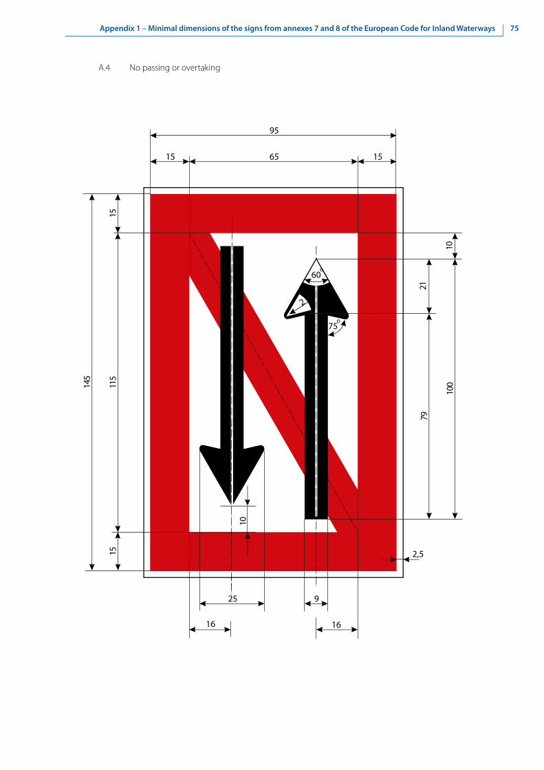
75Appendix 1 – Minimal dimensions of the signs from annexes 7 and 8 of the European Code for Inland Waterways
16
25
1511
5
145
15
15 1565
95
21
100
75o
10
2,5
60o
2
10
9
16
79
A.4 No passing or overtaking

76 Appendix 1 – Minimal dimensions of the signs from annexes 7 and 8 of the European Code for Inland Waterways
A.4.1 No passing or overtaking of convoys by convoys
14,5
21
7
1511
5
145
15
15 1565
95
18,5
100
55
2,5
55,5
18,5
7,5
2
60o
275
o
15

77Appendix 1 – Minimal dimensions of the signs from annexes 7 and 8 of the European Code for Inland Waterways
95 6515
15 1565
95
15
33
3814
9
48
5522
2,5
124,5
1919
A.5 No berthing on the side of the waterway on which the sign is placed (i.e. no anchoring or making fast to the bank)

78 Appendix 1 – Minimal dimensions of the signs from annexes 7 and 8 of the European Code for Inland Waterways
A.5.1 No berthing on the stretch of water whose breadth, measured from the sign, is shown in metres on the sign
44 100
10,5
1515
10,5
2,5
1515 21 218 87
100
2,5
15

79Appendix 1 – Minimal dimensions of the signs from annexes 7 and 8 of the European Code for Inland Waterways
95
12,5 2,5
38
14
2,5 7,5
34,5
65° 65°
46,7
40,7
34,7
22,8
21
10
12,5 26,52,5
12,5
95
12,5
1,3
2,5
6,5
A.6 No anchoring or trailing of anchors, cables or chains on the side of the waterway on which the sign is placed

80 Appendix 1 – Minimal dimensions of the signs from annexes 7 and 8 of the European Code for Inland Waterways
A.7 No making fast to the bank on the side of the waterway on which the sign is placed
24
65
95
5
520
25
6158
10
6515
37
36
67
7
5,2
1,5
1,5
15
95
2,5
15
36
5,2White band
6

81Appendix 1 – Minimal dimensions of the signs from annexes 7 and 8 of the European Code for Inland Waterways
95
12,5
7095
7012,5
12,5
15
25o
45 o
75o
60 o 20
7
7
2,5
A.8 No turning

82 Appendix 1 – Minimal dimensions of the signs from annexes 7 and 8 of the European Code for Inland Waterways
A.9 Do not create wash likely to cause damage
A.9a
61
1010
15,5
76
15
7,5
1010
10
3333
3333
65
95
15 15
1515
6595
2
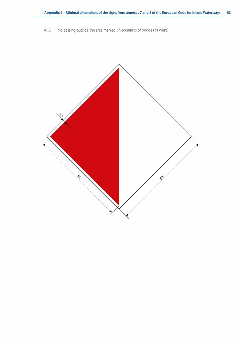
83Appendix 1 – Minimal dimensions of the signs from annexes 7 and 8 of the European Code for Inland Waterways
2,5
95100
A.10 No passing outside the area marked (in openings of bridges or weirs)

84 Appendix 1 – Minimal dimensions of the signs from annexes 7 and 8 of the European Code for Inland Waterways
A.12 Motorized craft prohibited
2,5 15 1565
100
1515
2,5
65 100
15

85Appendix 1 – Minimal dimensions of the signs from annexes 7 and 8 of the European Code for Inland Waterways
A.13 Sports or pleasure craft prohibited
2,5 15 1510 1045
100
1515
2,5
2525
15 100
15

86 Appendix 1 – Minimal dimensions of the signs from annexes 7 and 8 of the European Code for Inland Waterways
A.14 Water skiing prohibited
2,5 15 1565
100
1515
2,5
65 100
15

87Appendix 1 – Minimal dimensions of the signs from annexes 7 and 8 of the European Code for Inland Waterways
A.15 Sailing vessels prohibited
2,5 15 15 25
100
1 5
1 5
2 , 5
3 6
1 0 0
20 10 10
1 0
7,5
2,5
9
1 5
120 0
600

88 Appendix 1 – Minimal dimensions of the signs from annexes 7 and 8 of the European Code for Inland Waterways
A.16 All craft other than motorized vessels or sailing craft prohibited
14,5
9,5
100
108
1523
152,
5
100
2,5 15 1510 1045
33
15
120°
30°

89Appendix 1 – Minimal dimensions of the signs from annexes 7 and 8 of the European Code for Inland Waterways
A.17 Use of sailboards prohibited
2,5 15 1565
100
1515
2,5
65 100
15

90 Appendix 1 – Minimal dimensions of the signs from annexes 7 and 8 of the European Code for Inland Waterways
А.18 End of zone authorized for high speed navigation of small sport and pleasure craft
2,5 15 1565
100
1515
2,5
65 100
15

91Appendix 1 – Minimal dimensions of the signs from annexes 7 and 8 of the European Code for Inland Waterways
A.19 No launching or beaching of vessels
1515
2,5
65 100
15
2,5 15 1565
100
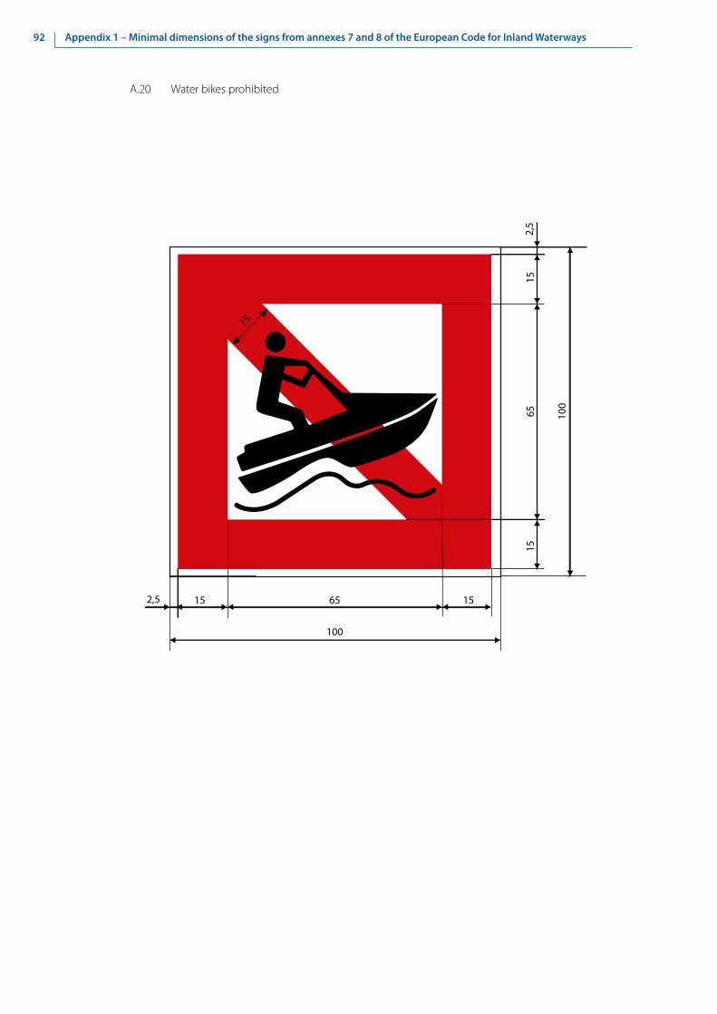
92 Appendix 1 – Minimal dimensions of the signs from annexes 7 and 8 of the European Code for Inland Waterways
А.20 Water bikes prohibited
1515
2,5
65 100
15
2,5 15 1565
100

93Appendix 1 – Minimal dimensions of the signs from annexes 7 and 8 of the European Code for Inland Waterways
B. Mandatory signs
B.1 Proceed in the direction shown by the arrow
145
95
10 60
2,5
39
15
75o
60o
11515
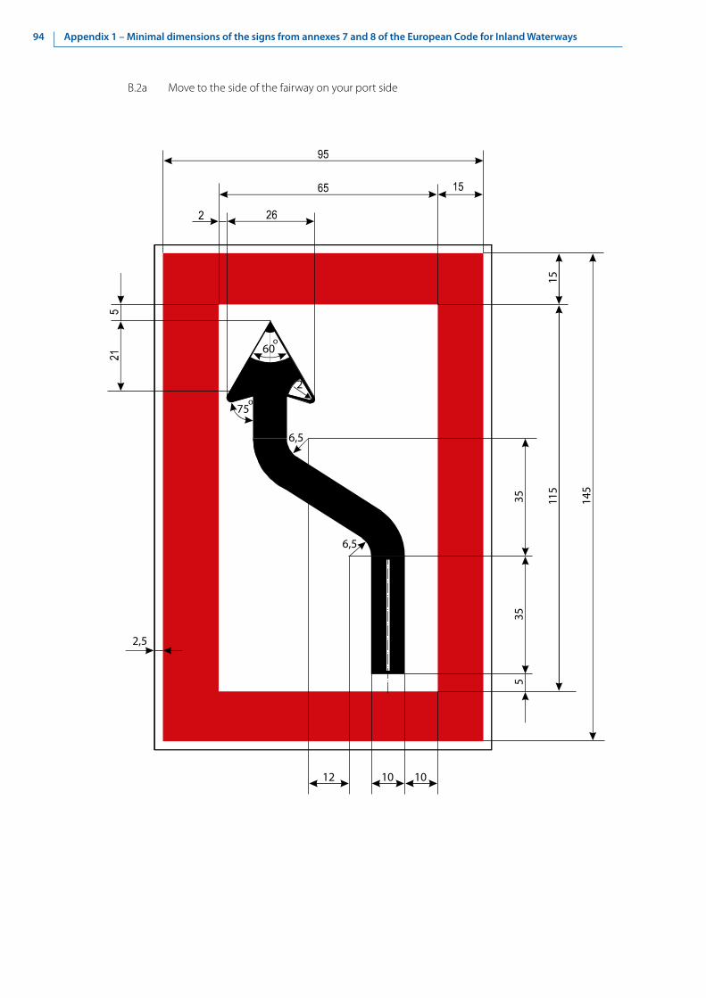
94 Appendix 1 – Minimal dimensions of the signs from annexes 7 and 8 of the European Code for Inland Waterways
B.2a Move to the side of the fairway on your port side
535
2,5
35 115
145
15
6,5
6,5
10 1012
60o
75o
2

95Appendix 1 – Minimal dimensions of the signs from annexes 7 and 8 of the European Code for Inland Waterways
B.2b Move to the side of the fairway on your starboard side
535
2,5
35115
145
15
6,5
6,5
60o
75o
2
95
10 10 12

96 Appendix 1 – Minimal dimensions of the signs from annexes 7 and 8 of the European Code for Inland Waterways
B.3a Keep to the side of the fairway on your port side
16
2,5
115
145
15
8
60o
75o
2
16
25
1021
,519
,515
33
153
15
95

97Appendix 1 – Minimal dimensions of the signs from annexes 7 and 8 of the European Code for Inland Waterways
B.3b Keep to the side of the fairway on your starboard side
16
2,5
115
145
15
8
60o
75o
2
16
1021
,515
33
153
15
95
19,5

98 Appendix 1 – Minimal dimensions of the signs from annexes 7 and 8 of the European Code for Inland Waterways
B.4a Cross fairway to port
32
35 115
145
15
10
6,5
60o
75o
2
6,5
2,5
10
3
40
105
262

99Appendix 1 – Minimal dimensions of the signs from annexes 7 and 8 of the European Code for Inland Waterways
B.4b Cross fairway to starboard
32
35115
145
10
75o
2
6,5
2,5
10
3
40
105
26 2
6,5
60o

100 Appendix 1 – Minimal dimensions of the signs from annexes 7 and 8 of the European Code for Inland Waterways
B.5 Stop as prescribed in the Regulations (see article 6.26, para. 2 and article 6.28, para. 1 of CEVNI)
15
2,5
65
95
9 5
6 5
1 5
48
1 5

101Appendix 1 – Minimal dimensions of the signs from annexes 7 and 8 of the European Code for Inland Waterways
4410
,5
15
17
10,5
1787
2,5
16
6595
15 65
95
B.6 Do not exceed the speed indicated (in km/h)

102 Appendix 1 – Minimal dimensions of the signs from annexes 7 and 8 of the European Code for Inland Waterways
B.7 Give a sound signal
40
6595
95
65
2,5

103Appendix 1 – Minimal dimensions of the signs from annexes 7 and 8 of the European Code for Inland Waterways
B.8 Keep a particularly sharp lookout
15
2,5
65
95
9 5
6 5
1 5
15
4 8

104 Appendix 1 – Minimal dimensions of the signs from annexes 7 and 8 of the European Code for Inland Waterways
B.9a Do not enter the main waterway until certain that this will not oblige vessels proceeding on it to change their course or speed
15
2,5
65
95
95 6515
8
2520
28,5

105Appendix 1 – Minimal dimensions of the signs from annexes 7 and 8 of the European Code for Inland Waterways
B.9b Do not cross the main waterway until certain that this will not oblige vessels proceeding on it to change their course or speed
15
2,5
6595
95 6515
8
2520
28,5

106 Appendix 1 – Minimal dimensions of the signs from annexes 7 and 8 of the European Code for Inland Waterways
B.11a Obligation to enter into a radiotelephone link
65
100
100
6515
VHF
51 15
152,
5
2,5

107Appendix 1 – Minimal dimensions of the signs from annexes 7 and 8 of the European Code for Inland Waterways
B.11b Obligation to enter into a radiotelephone link on the channel as indicated on the board
65
100
100
6515
5151 15
1115
2,5
2,5
VHF

108 Appendix 1 – Minimal dimensions of the signs from annexes 7 and 8 of the European Code for Inland Waterways
C. Restrictive signs
C.1 Depth of water limited
(a) C.1a
15
2,5
65
95
95 6515
50
35
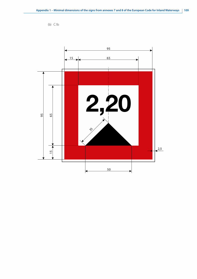
109Appendix 1 – Minimal dimensions of the signs from annexes 7 and 8 of the European Code for Inland Waterways
(b) C.1b
15
2,5
65
95
95 6515
50
35
2,20

110 Appendix 1 – Minimal dimensions of the signs from annexes 7 and 8 of the European Code for Inland Waterways
C.2 Headroom limited
(a) C.2a
15
2,5
65
9595 65
15
50
35

111Appendix 1 – Minimal dimensions of the signs from annexes 7 and 8 of the European Code for Inland Waterways
(b) C.2b
15
2,5
65
9595 65
15
50
35
7,50

112 Appendix 1 – Minimal dimensions of the signs from annexes 7 and 8 of the European Code for Inland Waterways
C.3 Width of passage or channel limited
(a) C.3a
15
2,5
65
95
9 5
6 5
1 5
30
21

113Appendix 1 – Minimal dimensions of the signs from annexes 7 and 8 of the European Code for Inland Waterways
(b) C.3b
15
2,5
65
95
95 6515
30
2145

114 Appendix 1 – Minimal dimensions of the signs from annexes 7 and 8 of the European Code for Inland Waterways
C.4 There are restrictions on navigation: see the information plate below the sign
15
2,5
65
95
95 6515

115Appendix 1 – Minimal dimensions of the signs from annexes 7 and 8 of the European Code for Inland Waterways
C.5 The channel lies at a distance from the right (left) bank (the figure shown on the sign indicates the distance in metres, measured from the sign, to which vessels should keep)
15
2,5
120
95 6515
852,5
20
11090o

116 Appendix 1 – Minimal dimensions of the signs from annexes 7 and 8 of the European Code for Inland Waterways
D. Recommendatory signs
D.1 Recommended opening
(a) D.1a In both directions
100 100
Black band
White band
1
2 , 5

117Appendix 1 – Minimal dimensions of the signs from annexes 7 and 8 of the European Code for Inland Waterways
(b) D.1c Only in the direction indicated (passage in the opposite direction prohibited)
100 100
1 1
2,5 2,5
100 100
≥20

118 Appendix 1 – Minimal dimensions of the signs from annexes 7 and 8 of the European Code for Inland Waterways
(c) D.1d
100
100
100
1
2,5
100
1
2,5
≥20
Black band
White band

119Appendix 1 – Minimal dimensions of the signs from annexes 7 and 8 of the European Code for Inland Waterways
D.2 You are recommended to keep within the area indicated (in openings of bridges or weirs)
D.2a
100
2,5
100

120 Appendix 1 – Minimal dimensions of the signs from annexes 7 and 8 of the European Code for Inland Waterways
D.3 You are recommended to proceed:
D.3a In the direction shown by the arrow
141
91
12 74
4,5
43,5
15 60o
75o
2

121Appendix 1 – Minimal dimensions of the signs from annexes 7 and 8 of the European Code for Inland Waterways
E. Informative signs
E.1a Entry permitted
120
100
2,5
2,5
20 47,547,5

122 Appendix 1 – Minimal dimensions of the signs from annexes 7 and 8 of the European Code for Inland Waterways
E.2 Overhead cable crossing
1071
21
4,5
49
34
91
6,5
32
10,5
20
4
80
15,5
24,52011
60o
91

123Appendix 1 – Minimal dimensions of the signs from annexes 7 and 8 of the European Code for Inland Waterways
E.3 Weir
12,5
141
10
13
91
158
10 1013 10
8
4,5
10

124 Appendix 1 – Minimal dimensions of the signs from annexes 7 and 8 of the European Code for Inland Waterways
E.4a Ferry-boat not moving independently
4,5
141
1515
1026
22,5
91
8 30 20

125Appendix 1 – Minimal dimensions of the signs from annexes 7 and 8 of the European Code for Inland Waterways
E.4b Ferry-boat moving independently
141
1515
3622,5
91
8 30 20
4,5

126 Appendix 1 – Minimal dimensions of the signs from annexes 7 and 8 of the European Code for Inland Waterways
E.5 Berthing (i.e. anchoring or making fast to the bank) permitted on the side of the waterway on which the sign is placed
91
27,5
28
91
10
1165
3616
4,5
18

127Appendix 1 – Minimal dimensions of the signs from annexes 7 and 8 of the European Code for Inland Waterways
E.5.1 Berthing permitted on the stretch of water of the breadth measured from, and shown on the board in metres
100
30
11
100
10,5 10,5 30 10
69
4,5
4,5
11

128 Appendix 1 – Minimal dimensions of the signs from annexes 7 and 8 of the European Code for Inland Waterways
E.5.2 Berthing permitted on the stretch of water bounded by the two distances measured from, and shown on the board in metres
200
30
11
10,5
10,5
3010
69
100
4,5
4,5 11
3030
1030

129Appendix 1 – Minimal dimensions of the signs from annexes 7 and 8 of the European Code for Inland Waterways
E.5.3 Maximum number of vessels permitted to berth abreast on the side of the waterway on which the sign is placed
10
100
10
11
100
694,
5
104,5 10
11
51
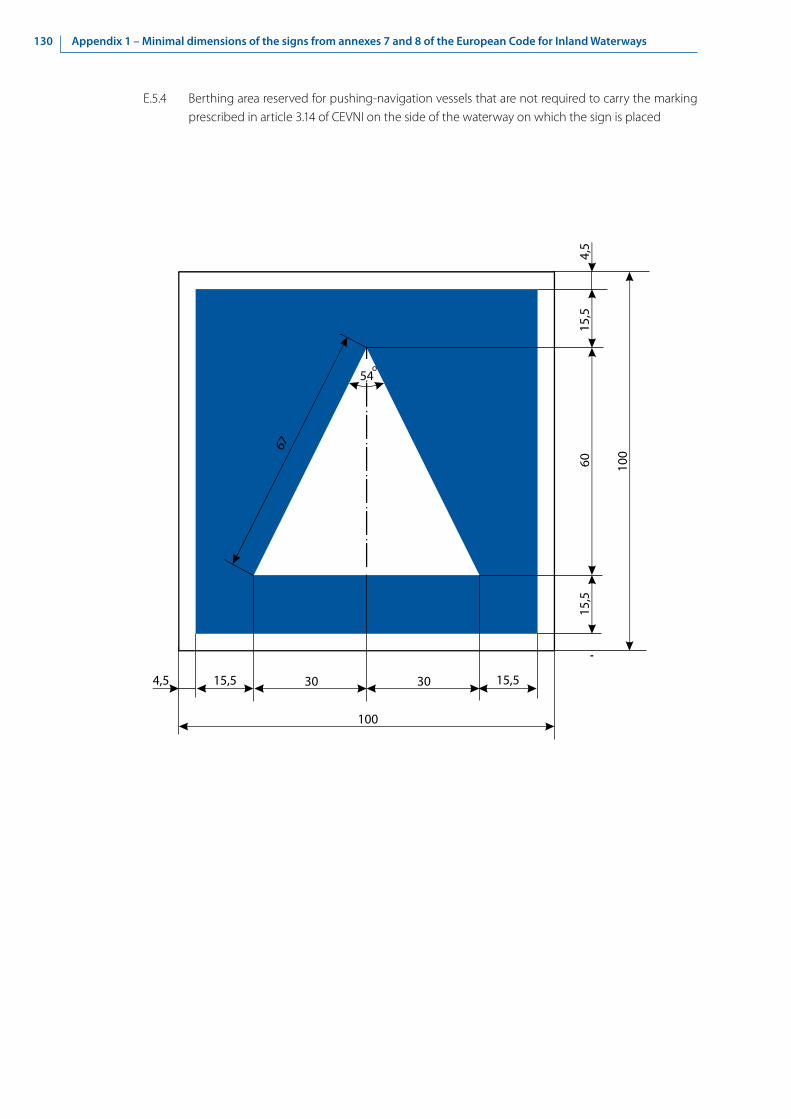
130 Appendix 1 – Minimal dimensions of the signs from annexes 7 and 8 of the European Code for Inland Waterways
E.5.4 Berthing area reserved for pushing-navigation vessels that are not required to carry the marking prescribed in article 3.14 of CEVNI on the side of the waterway on which the sign is placed
15,5
100
15,5
100
604,
5
304,5 15,5
15,5
30
67
54o

131Appendix 1 – Minimal dimensions of the signs from annexes 7 and 8 of the European Code for Inland Waterways
E.5.5 Berthing area reserved for pushing-navigation vessels that are required to carry one blue light or one blue cone under article 3.14, para. 1 of CEVNI on the side of the waterway on which the sign is placed
15,5
100
15,5
100
4,5
204,5 15,5
15,5
20
54o
10 10
1020
30
67
54o
22

132 Appendix 1 – Minimal dimensions of the signs from annexes 7 and 8 of the European Code for Inland Waterways
E.5.6 Berthing area reserved for pushing-navigation vessels that are required to carry two blue lights or two blue cones under article 3.14, para. 2 of CEVNI on the side of the waterway on which the sign is placed
15,5
100
15,5
100
4,5
204,5 15,5
15,5
20
67
54o
10 10
20
54o
22
2020

133Appendix 1 – Minimal dimensions of the signs from annexes 7 and 8 of the European Code for Inland Waterways
E.5.7 Berthing area reserved for pushing-navigation vessels that are required to carry three blue lights or three blue cones under article 3.14, para. 3 of CEVNI on the side of the waterway on which the sign is placed
15,5
100
15,5
100
4,5
22,54,5 15,5
15,5
22,5
67
54o
15
1515
1515
17 54o
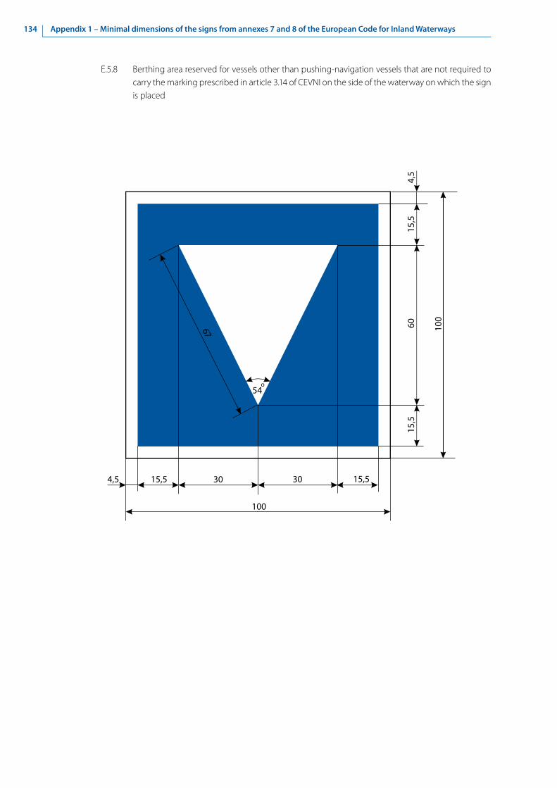
134 Appendix 1 – Minimal dimensions of the signs from annexes 7 and 8 of the European Code for Inland Waterways
E.5.8 Berthing area reserved for vessels other than pushing-navigation vessels that are not required to carry the marking prescribed in article 3.14 of CEVNI on the side of the waterway on which the sign is placed
15,5
100
15,5
100
604,
5
304,5 15,5
15,5
30
67
54o

135Appendix 1 – Minimal dimensions of the signs from annexes 7 and 8 of the European Code for Inland Waterways
E.5.9 Berthing area reserved for vessels other than pushing-navigation vessels that are required to carry one blue light or one blue cone under article 3.14, para. 1 of CEVNI on the side of the waterway on which the sign is placed
15,5
100
15,5
100
204,
5
204,5 15,5
15,5
20
67
54o
54o
22
1228
10 10

136 Appendix 1 – Minimal dimensions of the signs from annexes 7 and 8 of the European Code for Inland Waterways
E.5.10 Berthing area reserved for vessels other than pushing-navigation vessels that are required to carry two blue lights or two blue cones under article 3.14, para. 2 of CEVNI on the side of the waterway on which the sign is placed
15,5
100
15,5
100
204,
5
204,5 15,5
15,5
67
54o
22
54o
20 20
205
15

137Appendix 1 – Minimal dimensions of the signs from annexes 7 and 8 of the European Code for Inland Waterways
E.5.11 Berthing area reserved for vessels other than pushing-navigation vessels that are required to carry three blue lights or three blue cones under article 3.14, para. 3 of CEVNI on the side of the waterway on which the sign is placed
15,5
100
15,5
100
104,
5
22,54,5 15,5
15,5
67
54o
15 22,5
5
54o
1515
1517

138 Appendix 1 – Minimal dimensions of the signs from annexes 7 and 8 of the European Code for Inland Waterways
E.5.12 Berthing area reserved for all vessels that are not required to carry the marking prescribed in article 3.14 of CEVNI, on the side of the waterway on which the sign is placed
15,5
100
15,5
100
4,5
304,5 15,5
15,5
3030
30

139Appendix 1 – Minimal dimensions of the signs from annexes 7 and 8 of the European Code for Inland Waterways
E.5.13 Berthing area reserved for all vessels that are required to carry one blue light or one blue cone under article 3.14, para. 1of CEVNI, on the side of the waterway on which the sign is placed
15,5
100
15,5
100
4,5
204,5 15,5
15,5
1723
2010 10
20
54o
22

140 Appendix 1 – Minimal dimensions of the signs from annexes 7 and 8 of the European Code for Inland Waterways
E.5.14 Berthing area reserved for all vessels that are required to carry two blue lights or two blue cones under article 3.14, para. 2 of CEVNI
15,5
100
15,5
100
204,
5
204,5 15,5
15,5
20 20
2022
54o
515

141Appendix 1 – Minimal dimensions of the signs from annexes 7 and 8 of the European Code for Inland Waterways
E.5.15 Berthing area reserved for all vessels that are required to carry three blue lights or three blue cones under article 3.14, para. 3 of CEVNI, on the side of the waterway on which the sign is placed
15,5
100
15,5
100
154,
5
22,54,5 15,5
15,5
15 22,5
155
10
54o
17 15

142 Appendix 1 – Minimal dimensions of the signs from annexes 7 and 8 of the European Code for Inland Waterways
E.6 Anchoring or trailing of anchors, cables or chains permitted on the side of the waterway on which the sign is placed
100
91 74
16
18
33
39
6,5
8,5
27
10
7,5
40
65°65°
45,5
4,5

143Appendix 1 – Minimal dimensions of the signs from annexes 7 and 8 of the European Code for Inland Waterways
E.6.1 Use of spuds permitted
91 100
4,
5
91
100
4,5

144 Appendix 1 – Minimal dimensions of the signs from annexes 7 and 8 of the European Code for Inland Waterways
E.7 Making fast to the bank permitted on the side of the waterway on which the sign is placed
24
91
91
16
620
25
62
58
1036
67
76
1,5
1,5
5,2
37
4,5

145Appendix 1 – Minimal dimensions of the signs from annexes 7 and 8 of the European Code for Inland Waterways
E.7.1 Berthing area reserved for loading and unloading vehicles (maximum duration of berthing permitted may be added on an information plate below the board)
100
100
4,591
914,5

146 Appendix 1 – Minimal dimensions of the signs from annexes 7 and 8 of the European Code for Inland Waterways
E.8 Turning area
91
17
91
7
7
25o
12
45 o
32
60 o
75o 4,5

147Appendix 1 – Minimal dimensions of the signs from annexes 7 and 8 of the European Code for Inland Waterways
E.9 The waterways being approached are considered to be tributaries of this waterway
(a) E.9a
91
91
32
4,5
841
,5
27

148 Appendix 1 – Minimal dimensions of the signs from annexes 7 and 8 of the European Code for Inland Waterways
(b) E.9b
91
91
32
841
,5
27
4,5

149Appendix 1 – Minimal dimensions of the signs from annexes 7 and 8 of the European Code for Inland Waterways
(c) E.9c
91
91
32
841
,5
27
4,5
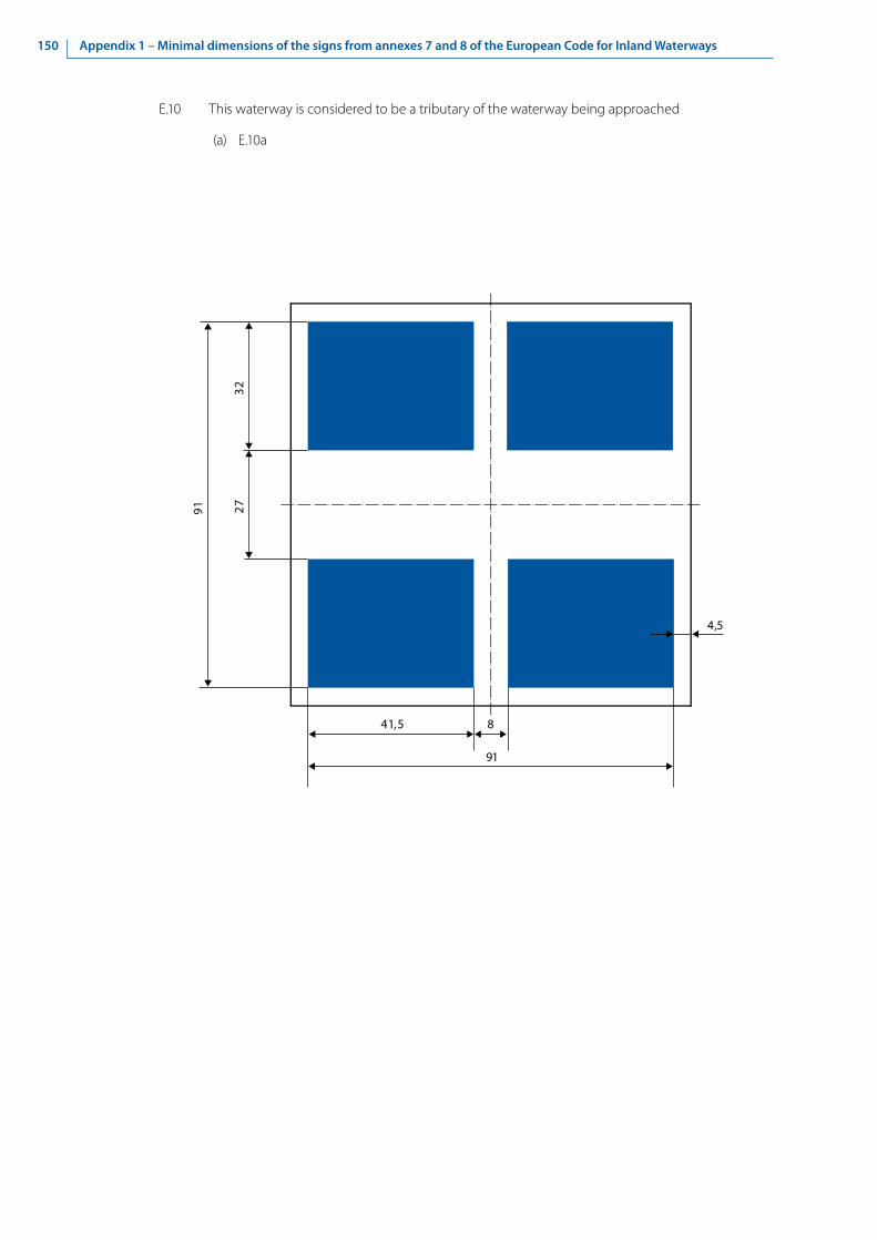
150 Appendix 1 – Minimal dimensions of the signs from annexes 7 and 8 of the European Code for Inland Waterways
E.10 This waterway is considered to be a tributary of the waterway being approached
(a) E.10a
91
91
32
4,5
841,5
27

151Appendix 1 – Minimal dimensions of the signs from annexes 7 and 8 of the European Code for Inland Waterways
(b) E.10b
91
91
32
841,5
27
4,5

152 Appendix 1 – Minimal dimensions of the signs from annexes 7 and 8 of the European Code for Inland Waterways
E.11 End of a prohibition or obligation applying to traffic in one direction only, or end of a restriction
(a) E.11a
91
91
12
4,5

153Appendix 1 – Minimal dimensions of the signs from annexes 7 and 8 of the European Code for Inland Waterways
(b) E.11b
91
141
12
4,5

154 Appendix 1 – Minimal dimensions of the signs from annexes 7 and 8 of the European Code for Inland Waterways
E.13 Drinking-water supply
40
30
10
6
14
20
11 70,5
91
1411
,5
4,5
2317
,517
91
105
12

155Appendix 1 – Minimal dimensions of the signs from annexes 7 and 8 of the European Code for Inland Waterways
E.14 Telephone
91
91
10,5
10
,5
56
57
4,5
10
21,5
33

156 Appendix 1 – Minimal dimensions of the signs from annexes 7 and 8 of the European Code for Inland Waterways
E.15 Motorized vessels permitted
91 100
4,5
91
100
4,5

157Appendix 1 – Minimal dimensions of the signs from annexes 7 and 8 of the European Code for Inland Waterways
E.16 Sports or pleasure craft permitted
2533
33
100
4,5
74
100
4,5 8,5
8,5
3

158 Appendix 1 – Minimal dimensions of the signs from annexes 7 and 8 of the European Code for Inland Waterways
E.17 Water skiing permitted
91 100
4,5
91
100
4,5

159Appendix 1 – Minimal dimensions of the signs from annexes 7 and 8 of the European Code for Inland Waterways
E.18 Sailing vessels permitted
47,5
152,
5
100
1511
4,5
5218
100
4,5
24 28
60°
120°

160 Appendix 1 – Minimal dimensions of the signs from annexes 7 and 8 of the European Code for Inland Waterways
E.19 Craft other than motorized vessels or sailing craft permitted
1510
1219
35
100
4,5
60
43
100
4,5 15,5
15,5
4
3

161Appendix 1 – Minimal dimensions of the signs from annexes 7 and 8 of the European Code for Inland Waterways
E.20 Use of sailboards permitted
100
4,5
91
91
100
4,5

162 Appendix 1 – Minimal dimensions of the signs from annexes 7 and 8 of the European Code for Inland Waterways
E.21 Zone authorized for high speed navigation of small sport and pleasure craft
100
4,5
91
91
100
4,5

163Appendix 1 – Minimal dimensions of the signs from annexes 7 and 8 of the European Code for Inland Waterways
E.22 Launching or beaching of small craft permitted
100
4,5
91
91
100
4,5

164 Appendix 1 – Minimal dimensions of the signs from annexes 7 and 8 of the European Code for Inland Waterways
E.23 Possibility of obtaining nautical information by radio-telephone on the channel indicated
11
VHF
100
4,5
91
91
100
4,5

165Appendix 1 – Minimal dimensions of the signs from annexes 7 and 8 of the European Code for Inland Waterways
E.24 Water bikes permitted
100
4,5
91
91
100
4,5

166 Appendix 1 – Minimal dimensions of the signs from annexes 7 and 8 of the European Code for Inland Waterways
Е.25 Electrical power supply point
100
4,5
91
91
100
4,5

167Appendix 1 – Minimal dimensions of the signs from annexes 7 and 8 of the European Code for Inland Waterways
Е.26 Winter harbour
15
2,5
65
95 15
65 95

168 Appendix 1 – Minimal dimensions of the signs from annexes 7 and 8 of the European Code for Inland Waterways
Е.26.1 Maximum number of vessels permitted to berth in winter harbour
15
2,5
65
95
1565 95

169Appendix 1 – Minimal dimensions of the signs from annexes 7 and 8 of the European Code for Inland Waterways
Е.27 Winter shelter
15
2,5
65
95
1525
1525
95

170 Appendix 1 – Minimal dimensions of the signs from annexes 7 and 8 of the European Code for Inland Waterways
Е.27.1 Maximum number of vessels permitted to berth in winter shelter (Maximum number of vessels permitted to berth abreast/ Maximum number of rows of vessels which are berthed abreast)
15
2,5
65
95
1525
1525
95
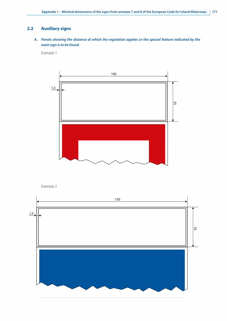
171Appendix 1 – Minimal dimensions of the signs from annexes 7 and 8 of the European Code for Inland Waterways
2.2 Auxiliary signs
A. Panels showing the distance at which the regulation applies or the special feature indicated by the main sign is to be found
Example 1
1,5
100
35
1,5
150
35
Example 2

172 Appendix 1 – Minimal dimensions of the signs from annexes 7 and 8 of the European Code for Inland Waterways
C. Panels giving explanations or additional information
Example
B. Pointers showing the direction of the section to which the main sign applies
Example
1,5
100
100
60°
1,5
100
35

173Appendix 1 – Minimal dimensions of the signs from annexes 7 and 8 of the European Code for Inland Waterways
100
60
42
35
30
100
60
35
40
60° 60°
3. Minimal dimensions of the signs contained in annex 8 to the European Code for Inland Waterways
3.1 Buoyage of fairway limits in the waterway
A. Right-hand side of the waterway
1.C Float with a topmark 1.D Spar
B. Left-hand side of the waterway
2.C Float with a topmark 2.D Spar

174 Appendix 1 – Minimal dimensions of the signs from annexes 7 and 8 of the European Code for Inland Waterways
C. Bifurcation of the waterway
3.C Float with a topmark 3.D Spar10
0
15
60
Ø 80
1515
15
1313
13
40

175Appendix 1 – Minimal dimensions of the signs from annexes 7 and 8 of the European Code for Inland Waterways
3.2 Bank marks indicating the position of the fairway
A. Bank marks indicating the position of the fairway in relation to the banks
(a) 4.B Channel near the right bank (without light)15
70
100
100

176 Appendix 1 – Minimal dimensions of the signs from annexes 7 and 8 of the European Code for Inland Waterways
(b) 5.B Channel near the left bank (without light)
1001,53
100
Black band
White band

177Appendix 1 – Minimal dimensions of the signs from annexes 7 and 8 of the European Code for Inland Waterways
B. Cross-overs
(a) 4.D Right bank (without light)
3
100
100
20

178 Appendix 1 – Minimal dimensions of the signs from annexes 7 and 8 of the European Code for Inland Waterways
(b) 5.D Left bank (without light)
100
100
20

179Appendix 1 – Minimal dimensions of the signs from annexes 7 and 8 of the European Code for Inland Waterways
3.3 Buoyage and marking of danger points and obstacles
A. Fixed marks
(a) 4.F Right-hand side
100
60°

180 Appendix 1 – Minimal dimensions of the signs from annexes 7 and 8 of the European Code for Inland Waterways
(b) 5.F Left-hand side
100
60°

181Appendix 1 – Minimal dimensions of the signs from annexes 7 and 8 of the European Code for Inland Waterways
(c) 6.B Bifurcation
100
60°

182 Appendix 1 – Minimal dimensions of the signs from annexes 7 and 8 of the European Code for Inland Waterways
3.4 Radar reflectors on marking signs and signals and navigable passes through
bridges
A. Radar reflectors on bridges
650
425
460
Fixture forhorizontaladjustmentof the azimuth

183Appendix 1 – Minimal dimensions of the signs from annexes 7 and 8 of the European Code for Inland Waterways
B. Radar reflectors on buoys and signs
300 or 600 mm
420
or 8
50 m
m
210 or 425 mm

184 Appendix 2 – Properties of lights

185Appendix 2 – Properties of lights
Appendix 2 - Properties of lights
1. Categories of luminous intensity
Lanterns are classified according to their horizontally emitted photometric luminous intensity Iph, in candelas (cd).
By analogy with luminous intensity for lights on board vessels, three distinct categories have been established, according to power.
Table 1
Category By analogy with light Intensity of white light [cd] Intensity of red/green/yellow light [cd]
1 Ordinary 2-9 0.8-3.5
2 Bright 9-35 3.5-20
3 Strong 35-100 20-50
2. Acceptable colours of lights
The colours of lights are described in a standard chromatic diagram pursuant to ISO 11664/CIE S 014. The range of colours accepted in the standard chromatic diagram is determined according to standard CIE S 004/E-2001, Class A.
The chromatic coordinates for the acceptable ranges are as follows:
Table 2
Colour 1 2 3 4
White x 0.300 0.440 0.440 0.300
y 0.342 0.432 0.382 0.276
Yellow x 0.536 0.547 0.613 0.593
y 0.444 0.452 0.387 0.387
Red x 0.660 0.680 0.690 0.710
y 0.320 0.320 0.290 0.290
Green x 0.009 0.284 0.209 0.028
y 0.720 0.520 0.400 0.400
The yellow/red/green colour ranges are limited in addition by the curve of the colour spectrum. The ranges of colours are set out in figure 1.
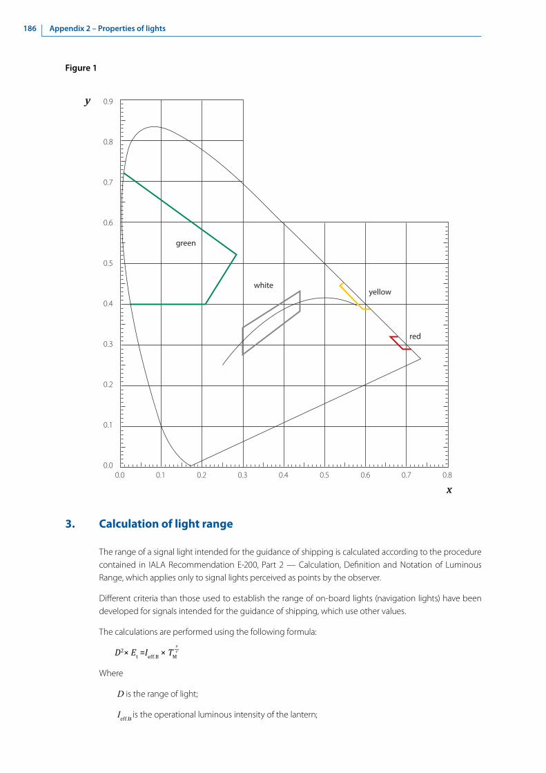
186 Appendix 2 – Properties of lights
Figure 1
white
green
yellow
red
y
x0.0 0.1 0.2 0.3 0.4 0.5 0.6 0.7 0.8
0.9
0.8
0.7
0.6
0.5
0.4
0.3
0.2
0.1
0.0
3. Calculation of light range
The range of a signal light intended for the guidance of shipping is calculated according to the procedure contained in IALA Recommendation E-200, Part 2 — Calculation, Definition and Notation of Luminous Range, which applies only to signal lights perceived as points by the observer.
Different criteria than those used to establish the range of on-board lights (navigation lights) have been developed for signals intended for the guidance of shipping, which use other values.
The calculations are performed using the following formula:
D2× Et =Ieff.B × TM
Where
D is the range of light;
Ieff.B is the operational luminous intensity of the lantern;
D-V

187Appendix 2 – Properties of lights
TM is the value for calculating visibility (describes the atmospheric transmissivity);
Et is the established limit of luminosity;
V is the meteorological visibility.
The calculation must be done numerically; the formula cannot be solved according to D.
The parameters given are as follows:
TM = 0.6;
Et = 2 × 10⁻⁷ lx for buoys with lights and simple bank lights with no background lighting;
Et = 10-6 lx to mark a cross-fairway axis with 2 or 3 lights with no background lighting;
Et = 2 × 10⁻⁶ lx for all lights with average background lighting (e.g. in a city);
Et = 2 × 10⁻⁵ lx for all lights with substantial background light (e.g. industrial facilities);
V = 1852 m.
The operational luminous intensity Ieff.B is a derivative of the photometric values Iph according to the following calculations:
Ieff.B= b × k × Iph
Where b = 0.75 is the conventionally accepted loss factor owing to dirt and light source degradation.
The effective intensity of rhythmic lights is taken into account by the degree of transmission k, which is usually calculated according to IALA Recommendation E-200, Part 4 — Determination and Calculation of Effective Intensity.
For the light emitting diodes (LEDs) that are used in most cases and that permit very high frequency commutation, the calculations may be simplified to the following:
k =
Where t equals the shortest time of light for the rhythm of light used (e.g. 0.5 s for “Fkl. 1s” and 2 s for “Glt. 4s”).
Table 3
The typical range with visibility TM = 0.6
Background lighting No No Average Substantial
Light limit Et [lx] 2×10⁻⁷ 10-6 (marking of the axis) 2×10⁻⁶ 2×10⁻⁵
Luminous intensity Ieff.B [cd] Range [m]
1 1 760 890 650 220
2 2 300 1 200 890 300
5 3 210 1 760 1 320 470
10 4 050 2 300 1 760 650
20 5 010 2 970 2 300 890
50 6 470 4 050 3 210 1 320
100 7 720 5 010 4 050 1 760
200 9 060 6 100 5 010 2 300
500 11 000 9 060 6 470 3 210
t—0.2s + t

188 Appendix 2 – Properties of lights

189Appendix 3 – Colours of reflected light for navigation signs
Appendix 3 - Colours of reflected light for navigation signs
The colours of light reflected by navigation signs (day markings) must conform with CIE publication No. 39-2 (TC-1.6) 1983 “Recommendations for Surface Colours for Visual Signalling”.
The following is taken from the Recommendations:
• Ordinary colours of materials (standard colours), in this case: red, yellow, green, blue, white and black;
• Fluorescent colours of materials (luminescent in daylight), in this case: red, green.
The acceptable colours are given in ranges and with a standard chromaticity diagram, specifying as well the requirements for intensity coefficients (luminance factors). The chromaticity coordinates for the ranges and intensity coefficients are shown in table 1. For colours adjacent to the spectral colour curve, the curve represents their external limit.
Table 1
Colour of the reflected light
Intensity coefficient 1 2 3 4
Standard colours x y x y x y x y
Red > 0.07 0.690 0.310 0.595 0.315 0.569 0.341 0.655 0.345
Yellow > 0.45 0.522 0.477 0.470 0.440 0.427 0.483 0.465 0.534
Green > 0.10 0.313 0.682 0.313 0.453 0.209 0.383 0.013 0.486
Blue > 0.05 0.078 0.171 0.196 0.250 0.225 0.184 0.137 0.038
White > 0.75 0.350 0.360 0.300 0.310 0.290 0.320 0.340 0.370
Black < 0.03 0.385 0.355 0.300 0.270 0.260 0.310 0.345 0.395
Colours luminescent in daylight x y x y x y x y
Red > 0.25 0.690 0.310 0.595 0.315 0.569 0.341 0.655 0.345
Green > 0.25 0.313 0.682 0.313 0.453 0.209 0.383 0.013 0.486
Figure 1 shows the admissible colour ranges on the standard chromaticity diagram. The ranges for ordinary colours and those that are luminescent in daylight (red/green) are identical; the colours differ only in their intensity coefficients.

190 Appendix 3 – Colours of reflected light for navigation signs
Figure 1
white
black
blue
green yellow
red
y
x0.0 0.1 0.2 0.3 0.4 0.5 0.6 0.7 0.8
0.9
0.8
0.7
0.6
0.5
0.4
0.3
0.2
0.1
0.0
A simplified description of the admissible colours can be presented using the RAL numbers from the internationally recognized RAL-Classic colour system.3
The colours below correspond with the CIE Recommendations and are preferred for use in transport technologies.
3 www.ralcolor.com, www.ral-farben.de.

191Appendix 3 – Colours of reflected light for navigation signs
Table 2
Number Designation Recommended use
RAL 1023 Traffic yellow Traffic signs, buoys
RAL 3020 Traffic red Traffic signs
RAL 3024 Luminous red Buoys, strongly visible traffic signs
RAL 3028 Pure red Buoys, sufficiently visible traffic signs
RAL 5017 Traffic blue Traffic signs
RAL 6024 Traffic green Traffic signs
RAL 6037 Pure green Buoys, sufficiently visible traffic signs
RAL 6038 Luminous green Buoys, strongly visible traffic signs
RAL 9016 Traffic white Traffic signs, buoys
RAL 9017 Traffic black Traffic signs, buoys
It is recommended that navigation sign surfaces, when they are not a part of the signs themselves, should be RAL 7042 traffic grey A or RAL 7043 traffic grey B.
It may be advisable to use adhesive light-reflective films on markers that are not equipped with lights. For the colours of light-reflective films, reference may be made to the relevant international standards for road transport.

192 Appendix 4 – Rhythmic lights

193Appendix 4 – Rhythmic lights
Appendix 4 - Rhythmic lights
Table 1 - Maximum periods of rhythmic characters of lights
Class Maximum period, s
Isophase light 12
Single-occulting light
15Single-flashing light
Group very quick light
Group-occulting light of two eclipses
20Long-flashing light
Group-flashing light of two flashes
Group quick light
Group-occulting light of three or more eclipses
30Group-flashing light of three or more flashes
Composite group-flashing light
Morse Code light
Note: The periods of rhythmic characters of lights should be selected in accordance with location-specific navigational requirements.

194 Appendix 4 – Rhythmic lights
Tabl
e 2
- Cla
ssifi
catio
n, s
peci
ficat
ions
and
app
licat
ion
of rh
ythm
ic li
ghts
Clas
sAb
brev
iatio
nG
ener
al d
escr
iptio
nSp
ecifi
catio
nPa
rtic
ular
use
1O
CCU
LTIN
G
LIG
HT
A lig
ht in
whi
ch th
e to
tal d
urat
ion
of li
ght i
n a
perio
d is
long
er th
an
the
tota
l dur
atio
n of
dar
knes
s and
th
e in
terv
als o
f dar
knes
s (ec
lipse
s)
are
usua
lly o
f equ
al d
urat
ion
A lig
ht in
whi
ch th
e to
tal d
urat
ion
of li
ght i
n a
perio
d is
clea
rly
long
er th
an th
e to
tal d
urat
ion
of d
arkn
ess a
nd a
ll th
e ec
lipse
s are
of
equ
al d
urat
ion.
1.1
Sing
le-
occu
lting
lig
ht
Oc
An o
ccul
ting
light
in w
hich
an
eclip
se is
regu
larly
repe
ated
The
dura
tion
of a
n ap
pear
ance
of l
ight
shou
ld n
ot b
e le
ss th
an
thre
e tim
es th
e du
ratio
n of
an
eclip
se.
The
perio
d sh
ould
not
be
less
than
2 s.
1 ≥
3 d
p
≥ 2
sEx
ampl
e: l
= 3
s; d
= 1
s; p
= 4
s
A sin
gle‐
occu
lting
whi
te li
ght i
ndic
ates
a sa
fe‐w
ater
m
ark.
A sin
gle-
occu
lting
yel
low
ligh
t ind
icat
es a
cro
ss-o
ver
mar
k.
1.2
Gro
up‐
occu
lting
lig
ht
Oc(
#),
e.g.
Oc(
2)An
occ
ultin
g lig
ht in
whi
ch a
gr
oup
of e
clip
ses,
spec
ified
in
num
ber,
is re
gula
rly re
peat
ed
The
appe
aran
ces o
f lig
ht b
etw
een
the
eclip
ses i
n a
grou
p ar
e of
equ
al d
urat
ion,
and
this
dura
tion
is cl
early
shor
ter t
han
the
dura
tion
of th
e ap
pear
ance
of l
ight
bet
wee
n su
cces
sive
grou
ps.
The
dura
tion
of a
n ap
pear
ance
of l
ight
bet
wee
n gr
oups
shou
ld
not b
e le
ss th
an th
ree
times
the
dura
tion
of a
n ap
pear
ance
of
light
with
in a
gro
up.
The
dura
tion
of a
n ap
pear
ance
of l
ight
with
in a
gro
up sh
ould
not
be
less
than
the
dura
tion
of a
n ec
lipse
. In
a g
roup
of t
wo
eclip
ses,
the
dura
tion
of a
n ec
lipse
toge
ther
w
ith th
e du
ratio
n of
an
appe
aran
ce o
f lig
ht w
ithin
the
grou
p sh
ould
not
be
less
than
1 s.
A gr
oup-
occu
lting
yel
low
ligh
t may
indi
cate
:•
a sp
ecia
l mar
k;•
a cr
oss-
over
mar
k.
In a
gro
up o
f thr
ee o
r mor
e ec
lipse
s, th
e du
ratio
n of
an
eclip
se
toge
ther
with
the
dura
tion
of a
n ap
pear
ance
of l
ight
with
in th
e gr
oup
shou
ld n
ot b
e le
ss th
an 2
s. T
he n
umbe
r of e
clip
ses i
n a
grou
p sh
ould
not
be
grea
ter t
han
four
in g
ener
al, a
nd sh
ould
be
five
only
as a
n ex
cept
ion.
l’ ≥ 3
lO
c(2)
l ≥
3 d
c ≥
1 s
Exam
ple:
l’ =
6 s;
l =
2 s;
d =
1 s;
c =
3 s;
p =
10
s
pd
l
p
cr
dd
l

195Appendix 4 – Rhythmic lights
Clas
sAb
brev
iatio
nG
ener
al d
escr
iptio
nSp
ecifi
catio
nPa
rtic
ular
use
1.3
Com
posit
e gr
oup‐
occu
lting
lig
ht
Oc(
#+#)
, e.
g. O
c(2+
1)A
light
sim
ilar t
o a
grou
p‐oc
culti
ng li
ght e
xcep
t tha
t su
cces
sive
grou
ps in
a p
erio
d ha
ve d
iffer
ent n
umbe
rs o
f ec
lipse
s
This
clas
s of l
ight
cha
ract
er is
not
reco
mm
ende
d be
caus
e it
is di
fficu
lt to
reco
gniz
e.l’’
≥ l’
Oc(
2+1)
l’ ≥
3 l
l ≥ d
c
≥ 1
sEx
ampl
e: l’’
= 9
s; l’
= 3
s; l
= 1
s; d
= 1
s; c
= 2
s; p
= 1
6 s
2IS
OPH
ASE
LIG
HT
ISO
A lig
ht in
whi
ch a
ll th
e du
ratio
ns
of li
ght a
nd d
arkn
ess a
re c
lear
ly
equa
l
The
perio
d sh
ould
nev
er b
e le
ss th
an 2
s, b
ut p
refe
rabl
y it
shou
ld
not b
e le
ss th
an 4
s in
ord
er to
redu
ce th
e ris
k of
con
fusio
n w
ith
occu
lting
or fl
ashi
ng li
ghts
of s
imila
r per
iods
. l = d
p
≥ 2
s
Exam
ple:
l =
d =
2 s;
p =
4 s
An is
opha
se w
hite
ligh
t may
indi
cate
:•
a sa
fe-w
ater
mar
k;•
a bi
furc
atio
n m
ark;
• a
mar
k ou
tsid
e th
e fa
irway
indi
catin
g ob
stac
les a
nd
dang
er p
oint
s, if
they
can
be
pass
ed o
n ei
ther
side
;•
an a
dvan
ce si
gnal
.
3FL
ASH
ING
LI
GH
TA
light
in w
hich
the
tota
l dur
atio
n of
ligh
t in
a pe
riod
is sh
orte
r tha
n th
e to
tal d
urat
ion
of d
arkn
ess a
nd
the
appe
aran
ces o
f lig
ht (fl
ashe
s)
are
usua
lly o
f equ
al d
urat
ion
A lig
ht in
whi
ch th
e to
tal d
urat
ion
of li
ght i
n a
perio
d is
clea
rly
shor
ter t
han
the
tota
l dur
atio
n of
dar
knes
s and
all
the
flash
es a
re
of e
qual
dur
atio
n.
A sin
gle‐
occu
lting
whi
te li
ght i
ndic
ates
a sa
fe‐w
ater
m
ark.
3.1
Sing
le-
flash
ing
light
FIA
flash
ing
light
in w
hich
a fl
ash
is re
gula
rly re
peat
ed
(at a
rate
of l
ess t
han
50 fl
ashe
s pe
r min
ute)
The
dura
tion
of th
e in
terv
al o
f dar
knes
s (ec
lipse
) bet
wee
n tw
o su
cces
sive
flash
es sh
ould
not
be
less
than
thre
e tim
es th
e du
ratio
n of
a fl
ash.
The
perio
d sh
ould
not
be
less
than
2 s
(or n
ot le
ss th
an 2
.5 s
in
thos
e co
untr
ies w
here
a q
uick
rate
of 5
0 fla
shes
per
min
ute
is us
ed).
d ≥
3 l
p ≥
2 s
Exam
ple:
d =
3 s;
l =
1 s;
p =
4 s
A sin
gle-
flash
ing
red
light
may
indi
cate
:•
right
-han
d sid
e of
the
fairw
ay;
• ch
anne
l nea
r the
righ
t ban
k.A
singl
e-fla
shin
g gr
een
light
may
indi
cate
:•
left-
hand
side
of t
he fa
irway
;•
chan
nel n
ear t
he le
ft b
ank.
A sin
gle-
flash
ing
yello
w li
ght m
ay in
dica
te:
• a
spec
ial m
ark;
• a
cros
s-ov
er m
ark.
3.2
Long
-fla
shin
g lig
ht
LFI
A sin
gle‐
flash
ing
light
in w
hich
an
app
eara
nce
of li
ght o
f not
less
th
an 2
s du
ratio
n (lo
ng fl
ash)
is
regu
larly
repe
ated
d ≥
3 l
l ≥ 2
s
Exam
ple:
d =
8 s;
l =
2 s;
p =
10
s
A lo
ng-fl
ashi
ng w
hite
ligh
t with
a p
erio
d of
10
s in
dica
tes a
safe
-wat
er m
ark.
p
cl’
l’’d
dd
l pd
l
pd
l
pd
l

196 Appendix 4 – Rhythmic lights
Clas
sAb
brev
iatio
nG
ener
al d
escr
iptio
nSp
ecifi
catio
nPa
rtic
ular
use
3.3
Gro
up-
flash
ing
light
Fl(#
) e.
g. F
l(2)
A fla
shin
g lig
ht in
whi
ch a
gro
up
of fl
ashe
s, sp
ecifi
ed in
num
ber,
is re
gula
rly re
peat
ed
The
eclip
ses b
etw
een
the
flash
es in
a g
roup
are
of e
qual
dur
atio
n,
and
this
dura
tion
is cl
early
shor
ter t
han
the
dura
tion
of th
e ec
lipse
be
twee
n su
cces
sive
grou
ps.
The
dura
tion
of a
n ec
lipse
bet
wee
n gr
oups
shou
ld n
ot b
e le
ss th
an
thre
e tim
es th
e du
ratio
n of
an
eclip
se w
ithin
a g
roup
.Th
e du
ratio
n of
an
eclip
se w
ithin
a g
roup
shou
ld n
ot b
e le
ss th
an
the
dura
tion
of a
flas
h.In
a g
roup
of t
wo
flash
es, t
he d
urat
ion
of a
flas
h to
geth
er w
ith th
e du
ratio
n of
the
eclip
se w
ithin
the
grou
p sh
ould
not
be
less
than
1 s.
In a
gro
up o
f thr
ee o
r mor
e fla
shes
, the
dur
atio
n of
a fl
ash
toge
ther
w
ith th
e du
ratio
n of
an
eclip
se w
ithin
a g
roup
shou
ld n
ot b
e le
ss
than
2 s
(or n
ot le
ss th
an 2
.5 s
in th
ose
coun
trie
s whe
re a
qui
ck ra
te
of 5
0 fla
shes
per
min
ute
is us
ed).
The
num
ber o
f flas
hes i
n a
grou
p sh
ould
not
be
grea
ter t
han
five
in
gene
ral, a
nd sh
ould
be
six o
nly
as a
n ex
cept
ion.
d’
≥ 3
dFI
(2)
d ≥
l c
≥ 1
s
Exam
ple:
d’ =
6 s;
d =
2 s;
l =
1 s;
c =
3 s;
p =
10
s
A gr
oup-
flash
ing
whi
te li
ght w
ith a
gro
up o
f tw
o fla
shes
, in
a pe
riod
of 5
s or
10
s, in
dica
tes a
n iso
late
d-da
nger
mar
k.A
grou
p-fla
shin
g w
hite
ligh
t with
a g
roup
of t
hree
fla
shes
indi
cate
s a b
ifurc
atio
n m
ark.
A gr
oup-
flash
ing
yello
w li
ght w
ith a
gro
up o
f fou
r, fiv
e or
(exc
eptio
nally
) six
flas
hes m
ay in
dica
te:
• a
spec
ial m
ark;
• a
cros
s-ov
er m
ark.
3.4
Com
posit
e gr
oup-
flash
ing
light
Fl(#
+#)
e.
g.
Fl(2
+1)
A fla
shin
g lig
ht in
whi
ch a
gro
up
of fl
ashe
s, sp
ecifi
ed in
num
ber,
is re
gula
rly re
peat
ed
Ligh
t cha
ract
ers s
houl
d be
rest
ricte
d to
(2+
1) fl
ashe
s in
gene
ral,
and
shou
ld b
e (3
+1)
flas
hes o
nly
as a
n ex
cept
ion.
d’’ ≥
d’
FI(2
+1)
d’
≥ 3
dd
≥ l
c ≥
1 s
Exam
ple:
d’’ =
9 s;
d’ =
3 s;
d
= 1
s; l
= 1
s; c
= 2
s; p
= 1
6 s
A co
mpo
site
grou
p-fla
shin
g ye
llow
ligh
t ind
icat
es a
sp
ecia
l mar
k.A
com
posit
e gr
oup‐
flash
ing
red
or g
reen
ligh
t with
a
grou
p of
(2 +
1) fl
ashe
s ind
icat
es a
mod
ified
late
ral
(pre
ferre
d‐ch
anne
l) m
ark.
p
cd’
dl
l
p
cd’
d’’
ll
ld

197Appendix 4 – Rhythmic lights
Clas
sAb
brev
iatio
nG
ener
al d
escr
iptio
nSp
ecifi
catio
nPa
rtic
ular
use
4Q
UIC
K LI
GH
TA
light
in w
hich
flas
hes a
re
repe
ated
at a
rate
of n
ot le
ss th
an
50 fl
ashe
s per
min
ute
but l
ess
than
80
flash
es*
per m
inut
e
A lig
ht in
whi
ch id
entic
al fl
ashe
s are
repe
ated
at t
he ra
te o
f 60
flas
hes p
er m
inut
e.
4.1
Cont
inuo
us
quic
k lig
htQ
A qu
ick
light
in w
hich
a fl
ash
is re
gula
rly re
peat
edd
≥ l
1 s ≤
p ≤
1.2
s
Exam
ple:
l =
d =
0.5
s; p
= 1
s
A co
ntin
uous
qui
ck w
hite
ligh
t may
indi
cate
:•
a no
rth
card
inal
mar
k;•
a bi
furc
atio
n m
ark;
• a
mar
k ou
tsid
e th
e ch
anne
l in
dica
ting
obst
acle
s an
d da
nger
poi
nts,
if th
ey c
an b
e pa
ssed
on
eith
er
side.
4.2
Gro
up
quic
k lig
htQ
(#)
e.g.
Q(3
); Q
(9);
Q(6
)+LF
l
A qu
ick
light
in w
hich
a sp
ecifi
ed
grou
p of
flas
hes i
s reg
ular
ly
repe
ated
The
num
ber o
f flas
hes i
n a
grou
p sh
ould
be
thre
e or
nin
e.
An e
xcep
tiona
l lig
ht c
hara
cter
is re
serv
ed to
indi
cate
a so
uth
card
inal
mar
k.Q
(3)
d ≥
l d’
≥ d
1
s ≤ c
≤ 1
.2 s
Exam
ple:
d’ =
7.5
s; l
= d
= 0
.5 s;
c =
1 s;
p =
10
s
A gr
oup
quic
k w
hite
ligh
t with
a g
roup
of t
hree
flas
hes,
in a
per
iod
of 1
0 s,
indi
cate
s an
east
car
dina
l mar
k.
Q(9
)d
≥ l
d’ ≥
d
1 s ≤
c ≤
1.2
sEx
ampl
e: d
’ = 6
.5 s;
l =
d =
0.5
s; c
= 1
s; p
= 1
5 s
A gr
oup
quic
k w
hite
ligh
t with
a g
roup
of n
ine
flash
es,
in a
per
iod
of 1
5 s,
indi
cate
s a w
est c
ardi
nal m
ark.
Q(6
) +LF
1d
≥ l
l’ ≥ 2
s 1
s ≤ c
≤ 1
.2 s
Exam
ple:
d’ =
7 s;
l’ =
2 s;
l =
d =
0.5
s; c
= 1
s; p
= 1
5 s
A gr
oup
quic
k w
hite
ligh
t with
a g
roup
of s
ix fl
ashe
s fo
llow
ed b
y a
long
flas
h of
not
less
than
2 s
dura
tion,
in
a pe
riod
of 1
5 s,
indi
cate
s a so
uth
card
inal
mar
k.
5.VE
RY Q
UIC
K LI
GH
TA
light
in w
hich
flas
hes a
re
repe
ated
at a
rate
of n
ot le
ss th
an
80 fl
ashe
s per
min
ute
but l
ess
than
160
flas
hes*
per
min
ute
A lig
ht in
whi
ch id
entic
al fl
ashe
s are
repe
ated
at t
he ra
te o
f 12
0 fla
shes
per
min
ute.
pl d
p
ld’
cd l d
p
d’
c l
p
d’r
cd
* Th
e co
mpe
tent
aut
horit
ies s
houl
d ch
oose
the
rate
s for
all
thei
r qui
ck li
ghts
and
ver
y qu
ick
light
s: ei
ther
60
and
120
flash
es p
er m
inut
e or
50
and
100
flash
es p
er m
inut
e.

198 Appendix 4 – Rhythmic lights
Clas
sAb
brev
iatio
nG
ener
al d
escr
iptio
nSp
ecifi
catio
nPa
rtic
ular
use
5.1
Cont
inuo
us
very
qui
ck
light
VQA
very
qui
ck li
ght i
n w
hich
a fl
ash
is re
gula
rly re
peat
edd
≥ l
0.5
s ≤ p
≤ 1
.6 s
Exam
ple:
l =
d =
0.2
5 s;
p =
0.5
s
A co
ntin
uous
qui
ck sc
intil
latin
g w
hite
ligh
t ind
icat
es a
no
rth
card
inal
mar
k.
5.2
G
roup
ver
y qu
ick
light
VQ(#
) e.
g. V
Q(3
);
VQ(9
); VQ
(6)+
LF
l
A ve
ry q
uick
ligh
t in
whi
ch a
sp
ecifi
ed g
roup
of fl
ashe
s is
regu
larly
repe
ated
The
num
ber o
f flas
hes i
n a
grou
p sh
ould
be
thre
e or
nin
e. A
n ex
cept
iona
l lig
ht c
hara
cter
is re
serv
ed fo
r use
to in
dica
te a
sout
h ca
rdin
al m
ark.
VQ(3
)d’
> 1
.5 s
d ≥
l0.
5 s ≤
c ≤
0.6
sEx
ampl
e: d
’ = 3
.75
s; l =
d =
0.2
5 s;
c =
0.5
s; p
= 5
s
A gr
oup
very
qui
ck w
hite
ligh
t with
a g
roup
of s
ix
flash
es, i
n a
perio
d of
5 s,
indi
cate
s an
east
car
dina
l m
ark.
VQ(9
)d’
> 1
.5 s
d ≥
l0.
5 s ≤
c ≤
0.6
sEx
ampl
e: d
’ = 5
.75
s; l =
d =
0.2
5 s;
c =
0.5
s; p
= 1
0 s
A gr
oup
very
qui
ck w
hite
ligh
t with
a g
roup
of n
ine
flash
es, i
n a
perio
d of
10
s, in
dica
tes a
wes
t car
dina
l m
ark.
VQ(6
) +LF
1d’
≥ 1
.5 l’
l’ ≥ 2
sd
≥ l
0.5
s ≤ c
≤ 0
.6 s
Exam
ple:
d’ =
5 s;
l’ =
2 s;
l =
d =
0.2
5 s;
c =
0.5
s; p
= 1
0 s
A gr
oup
very
qui
ck w
hite
ligh
t with
a g
roup
of s
ix
flash
es fo
llow
ed b
y a
long
flas
h of
not
less
than
2 s
dura
tion,
in a
per
iod
of 1
0 s,
indi
cate
s a so
uth
card
inal
m
ark.
6U
LTRA
Q
UIC
K LI
GH
T
A lig
ht in
whi
ch fl
ashe
s are
re
peat
ed a
t a ra
te o
f not
less
than
16
0 fla
shes
per
min
ute
and
not
mor
e th
an 3
00 fl
ashe
s per
min
ute
A lig
ht in
whi
ch id
entic
al fl
ashe
s are
repe
ated
at t
he ra
te o
f 24
0 fla
shes
per
min
ute.
6.1
Cont
inuo
us
ultr
a qu
ick
light
UQ
An u
ltra
quic
k lig
ht in
whi
ch
a fla
sh is
regu
larly
repe
ated
pld
p
ldd’
c ldd’
pc ld
rd’
pc

199Appendix 4 – Rhythmic lights
Clas
sAb
brev
iatio
nG
ener
al d
escr
iptio
nSp
ecifi
catio
nPa
rtic
ular
use
7M
ORS
E CO
DE
LIG
HT
Mo(
#)
e.g.
Mo(
A)A
light
in w
hich
app
eara
nces
of
ligh
t of t
wo
clea
rly d
iffer
ent
dura
tions
are
gro
uped
to
repr
esen
t a c
hara
cter
or
char
acte
rs in
the
Mor
se C
ode
Ligh
t cha
ract
ers s
houl
d be
rest
ricte
d to
a si
ngle
lett
er in
the
Mor
se C
ode
in g
ener
al, a
nd sh
ould
be
two
lett
ers o
nly
as a
n ex
cept
ion.
Th
e du
ratio
n of
a “d
ot” s
houl
d be
abo
ut 0
.5 s,
and
the
dura
tion
of a
“das
h” sh
ould
not
be
less
than
thre
e tim
es th
e du
ratio
n of
a
“dot
”. l’ ≥
3 l
Mo(
A)
d ≥
ll =
0.5
sEx
ampl
e: l’
= 1
.5 s;
l =
0.5
s; d
= 0
.5 s;
d’ =
4.5
s; p
= 7
s
A M
orse
Cod
e w
hite
ligh
t with
the
singl
e ch
arac
ter “
A”
indi
cate
s a sa
fe‐w
ater
mar
k.A
Mor
se C
ode
yello
w li
ght,
but n
ot w
ith e
ither
of t
he
singl
e ch
arac
ters
“A” o
r “U
”, ind
icat
es a
spec
ial m
ark.
8FI
XED
AN
D
FLAS
HIN
G
LIG
HT
F+ re
leva
nt
char
ac-t
er
abbr
e-vi
atio
n,
e.g.
FFl
, FIso
A lig
ht in
whi
ch a
low
inte
nsity
fix
ed li
ght p
hase
is c
ombi
ned
with
a fl
ashi
ng p
hase
of h
ighe
r lu
min
ous i
nten
sity
com
plia
nt
with
pre
cedi
ng c
lass
es o
f rh
ythm
ic c
hara
cter
s in
this
tabl
e
Impl
emen
tatio
n of
an
FFl r
hyth
mic
cha
ract
er is
show
n be
low
. O
ther
com
bina
tions
may
be
impl
emen
ted
as n
eces
sary
. d
≥ 3
ll ≤
1 s
Exam
ple:
d =
3 s;
l =
1 s;
p =
4 s
9AL
TERN
A-TI
NG
LIG
HT
Al##
e.
g. A
lWR
A lig
ht sh
owin
g di
ffere
nt c
olou
rs
alte
rnat
ely
This
clas
s of l
ight
cha
ract
er sh
ould
be
used
with
car
e, a
nd e
ffort
s sh
ould
be
mad
e to
ens
ure
that
the
diffe
rent
col
ours
app
ear
equa
lly v
isibl
e to
an
obse
rver
.AI
WR
l d
l ≤ 1
s
Exam
ple:
l =
d =
2 s;
p =
4 s
10O
CCU
LTIN
G
ALTE
RNA-
TIN
G L
IGH
T
OcA
lA
light
show
ing
diffe
rent
col
ours
al
tern
atel
y an
d a
light
in w
hich
th
e to
tal d
urat
ion
of li
ght i
n a
perio
d is
long
er th
an th
e to
tal
dura
tion
of d
arkn
ess a
nd th
e in
terv
als o
f dar
knes
s (ec
lipse
s)
are
of e
qual
dur
atio
n
This
clas
s of l
ight
is p
artic
ular
to th
e us
e of
New
Dan
ger M
arki
ng,
and
effor
ts sh
ould
be
mad
e to
ens
ure
that
the
diffe
rent
col
ours
ap
pear
equ
ally
visi
ble
to a
n ob
serv
er.
OcA
lBY
Exam
ple:
l =
1 s;
d =
0.5
s; p
= 3
s
An o
ccul
ting
alte
rnat
ing
blue
and
yel
low
ligh
t ind
icat
es
a N
ew D
ange
r mar
k.
ld
rd’
p
ld
p
ld
p ld
ld

200 Appendix 4 – Rhythmic lights

201Appendix 5 – Recommendations for the lighting of traffic signs
Appendix 5 - Recommendations for the lighting of traffic signs4
1. General provisions
The lighting of signs shall be turned on only at night. During daytime, the sign must be identifiable with natural lighting.
The lighting may be arranged either with an external, backward-facing floodlight located in front of the sign or with lighting from the inside of translucent panels (internally backlit signs) as shown in figure 1.
Figure 1
2. External backward-facing lighting of signs
External backward-facing lighting from a floodlight located above the sign is generally arranged with floodlights affixed above or below the sign board. For tall signs it is advisable to affix two floodlights (above and below). For wide signs it is possible to affix several floodlights in a line.
To avoid undesirable dark spots and glare, the floodlights must be located in such a way that they do not block a view from an angle of 7 degrees from the horizontal, drawn from the sign’s top or bottom edge.
Figure 2
4 This appendix is based on the provisions of European standard EN 12899-1 “Fixed, vertical road traffic signs”. Administrations can apply other international or national standards provided that the same safety level is ensured.
Sign
boa
rd
Light re�ected by the sign
Backward - facing �oodlight
Light sources
Translucent sign
Light di�used by the sign
Sign
boa
rd
Sign
boa
rd
Backward - facing �oodlight
Backward - facing �oodlightunder the sign
7°
7°

202 Appendix 5 – Recommendations for the lighting of traffic signs
The type of lighting is always determined by the readability of the sign illuminated by the backward-facing light. Minimum dimensions of signs are given in appendix 1 to these Guidelines.
With some boards, the illuminated surface is identical to the board itself. If several boards conveying a single message are installed, for instance with additional text plates, the lighting requirements refer to the overall surface of the combined boards.
The recommended dimensions of the backward-illuminated surface of a sign board are shown in figure 3:
(a) a single board;
(b) a board with an additional plate.
Figure 3
As for the backward-illuminated surface, the following lighting parameters are recommended:
• in areas with insignificant background light levels (for example, outside of city limits), the luminosity measured on-site should range from 40 lx to 100 lx;5
• in areas with increased background light levels (for example, within city limits), the luminosity measured on-site should range from 100 lx to 400 lx.6
The uniformity of lighting is established by the ratio between the minimum luminosity (Emin) and the maximum luminosity (Emax) on the back-illuminated surface. In all cases Emin:Emax ≥ 1:10.7
For the lighting, a white lamp with a colour temperature between 3500 K and 4500 K is used. Care must be taken to ensure that the sign colours are reproduced when the backward-facing light is white.
3. Internally backlit signs
It is recommended to use intensity class L18 for signs in areas with insignificant background light and intensity class L2 for those with increased background light levels.
As for the uniformity of the lighting, the aim should be to reach class U1 (1:10).
5 Class E1 of EN 12899.6 Class E2 of EN 12899.7 Class UE1 of EN 12899.8 Intensity and uniformity classes in EN 12899.
100
100
10035
13515
0
a) b)

203Appendix 5 – Recommendations for the lighting of traffic signs

204 Appendix 6 – Examples of variable-message traffic signs

205Appendix 6 – Examples of variable-message traffic signs
Appendix 6 - Examples of variable-message traffic signs9
1. Mechanical boards
A. Scrolling sign boards
Boards with a scrolled band of sign images are useful as variable message traffic signs, in particular for displaying the signs in annex 7 to CEVNI.
The sign images are placed on a band that is scrolled vertically on rollers. The rollers place the currently valid image in the window for display.
Figure 1
The advantage of scrolling sign boards is that they make it possible to display a large number of signs.
B. Trivision boards
Trivision boards are used preferably to display two different signs from annex 7 to CEVNI. This technique is limited to displaying three distinct sign images. Generally, the third position is reserved as blank, with a grey surface.
Figure 2
In comparison with boards using scrolling bands, the advantage of trilons is that they are mechanically more robust. At the same time, it is not necessary to produce sign images on a flexible surface, which makes it possible to use paints and films of proven value for use on navigation signs.
C. Other mechanical boards
There are many mechanical systems for information boards (for example, including flip-disk boards), with many designed for use in indoor spaces (such as transport terminals or stations). For navigation signs, which generally have to bear the brunt of weather conditions, the service life of such systems is often negligible; they often require servicing.
9 This appendix is based on the provisions of European standard EN 12966-1 “Vertical road signs — Variable message signs — Part 1: Product standard”. Administrations can apply other international or national standards provided that the same safety level is ensured.
Band
Displaywindow
RollerContent 1
Content 2
Displaywindow
Rotating trilons
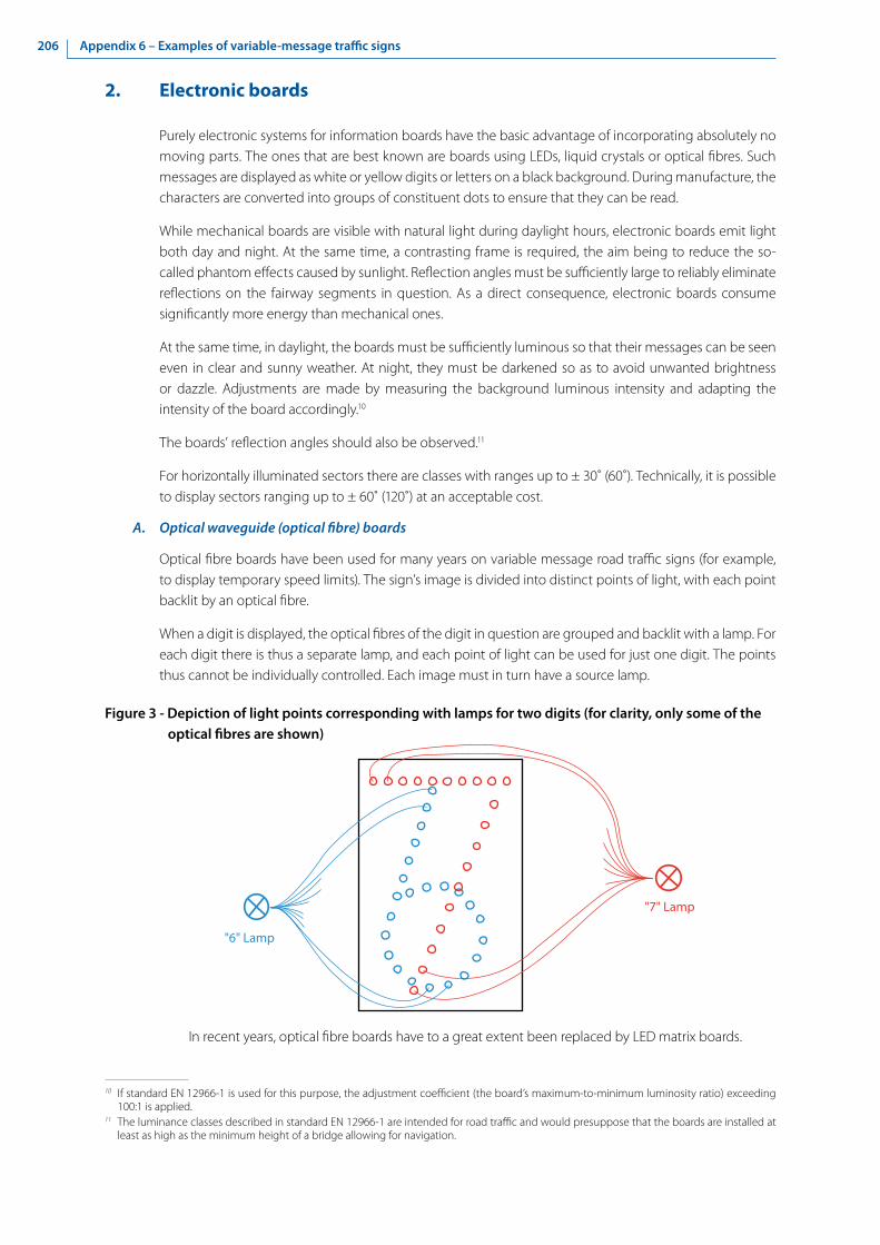
206 Appendix 6 – Examples of variable-message traffic signs
2. Electronic boards
Purely electronic systems for information boards have the basic advantage of incorporating absolutely no moving parts. The ones that are best known are boards using LEDs, liquid crystals or optical fibres. Such messages are displayed as white or yellow digits or letters on a black background. During manufacture, the characters are converted into groups of constituent dots to ensure that they can be read.
While mechanical boards are visible with natural light during daylight hours, electronic boards emit light both day and night. At the same time, a contrasting frame is required, the aim being to reduce the so-called phantom effects caused by sunlight. Reflection angles must be sufficiently large to reliably eliminate reflections on the fairway segments in question. As a direct consequence, electronic boards consume significantly more energy than mechanical ones.
At the same time, in daylight, the boards must be sufficiently luminous so that their messages can be seen even in clear and sunny weather. At night, they must be darkened so as to avoid unwanted brightness or dazzle. Adjustments are made by measuring the background luminous intensity and adapting the intensity of the board accordingly.10
The boards’ reflection angles should also be observed.11
For horizontally illuminated sectors there are classes with ranges up to ± 30˚ (60˚). Technically, it is possible to display sectors ranging up to ± 60˚ (120˚) at an acceptable cost.
A. Optical waveguide (optical fibre) boards
Optical fibre boards have been used for many years on variable message road traffic signs (for example, to display temporary speed limits). The sign’s image is divided into distinct points of light, with each point backlit by an optical fibre.
When a digit is displayed, the optical fibres of the digit in question are grouped and backlit with a lamp. For each digit there is thus a separate lamp, and each point of light can be used for just one digit. The points thus cannot be individually controlled. Each image must in turn have a source lamp.
Figure 3 - Depiction of light points corresponding with lamps for two digits (for clarity, only some of the optical fibres are shown)
In recent years, optical fibre boards have to a great extent been replaced by LED matrix boards.
10 If standard EN 12966-1 is used for this purpose, the adjustment coefficient (the board’s maximum-to-minimum luminosity ratio) exceeding 100:1 is applied.
11 The luminance classes described in standard EN 12966-1 are intended for road traffic and would presuppose that the boards are installed at least as high as the minimum height of a bridge allowing for navigation.
"6" Lamp
"7" Lamp

207Appendix 6 – Examples of variable-message traffic signs
B. Light-emitting diode (LED) matrix boards
In the case of a LED matrix, each separate point of the image is displayed by a diode that can be independently turned on and off. In principle, such boards can be freely programmed (using a complete matrix), thus making it possible to display any message.
Figure 4 - Board with individually controlled light emitting diodes displaying digits
Often, though, only seven segments required to display digits are connected. As fewer diodes are used, the electronic control is simplified, which results in savings. To reduce costs, it is possible to pre-programme groups of LEDs to display only the messages that are required.
Figure 5 - Board composed of seven segments with separate light emitting diodes
C. Liquid crystal displays (LCDs)
Boards using liquid crystal displays (LCDs) are composed of a regularly illuminated surface placed behind a film of liquid crystals, which blocks areas of the image, thus creating the desired figure. For large boards, monochrome images are preferred, although colour images are possible as well. Diodes have recently been employed to backlight the surface, while fluorescent lamps were previously used.
The advantage of this kind of board is that it produces a very sharp, detailed image, with such high luminosity and contrast that the boards can be used in daylight.
There is a technical disadvantage, though, as the optical characteristics of the liquid crystal film are such that only a small part (less than 25 per cent) of the generated light is displayed. For the same luminosity, boards of this kind require significantly more power than those using LED matrices.
In addition, liquid crystal displays shall be protected against temperature changes and humidity, which involves high costs.

Notes

ISBN 978-92-1-117179-2
The European Code for Signs and Signals on Inland Waterways (SIGNI) provides recommendations for the competent authorities for the installation and application of buoyage and marking on European inland waterways contained in the fifth revision of CEVNI (TRANS/SC.3/115/Rev.5). This new edition of SIGNI is based on revision 2 of Resolution No. 22 and the Guidelines for Waterways Signs and Marking (Resolution No. 59, revision 2).
This edition has been prepared with the participation of River Commissions and the CEVNI Expert Group as well as contributions from the Chairs of the Joint International VTT and Inland ECDIS Expert Group and the International Association of Marine Aids to Navigation and Lighthouse Authorities (IALA).
SIG
NI
Euro
pean
Cod
e fo
r Sig
ns a
nd S
igna
ls
on In
land
Wat
erw
ays
UN
ITED N
ATION
S
Palais des NationsCH - 1211 Geneva 10, SwitzerlandTelephone: +41(0)22 917 12 34E-mail: [email protected]: http://www.unece.org
United Nations Economic Commission for Europe
Design and Printing at United Nations, Geneva – 1833203 (E) – March 2019 – 500 – ECE/TRANS/SC.3/208
SIGN
I European Code for Signs and Signals on Inland Waterw
aysU
NECE