UNDERWATER WALL CLIMBING ROBOT FOR NUCLEAR...
8
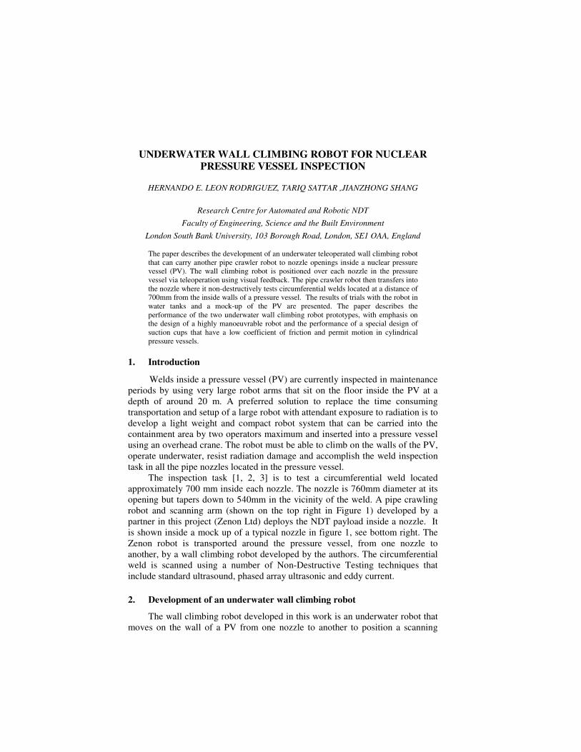
UNDERWATER WALL CLIMBING ROBOT FOR NUCLEAR PRESSURE VESSEL INSPECTION HERNANDO E. LEON RODRIGUEZ, TARIQ SATTAR ,JIANZHONG SHANG Research Centre for Automated and Robotic NDT Faculty of Engineering, Science and the Built Environment London South Bank University, 103 Borough Road, London, SE1 OAA, England The paper describes the development of an underwater teleoperated wall climbing robot that can carry another pipe crawler robot to nozzle openings inside a nuclear pressure vessel (PV). The wall climbing robot is positioned over each nozzle in the pressure vessel via teleoperation using visual feedback. The pipe crawler robot then transfers into the nozzle where it non-destructively tests circumferential welds located at a distance of 700mm from the inside walls of a pressure vessel. The results of trials with the robot in water tanks and a mock-up of the PV are presented. The paper describes the performance of the two underwater wall climbing robot prototypes, with emphasis on the design of a highly manoeuvrable robot and the performance of a special design of suction cups that have a low coefficient of friction and permit motion in cylindrical pressure vessels. 1. Introduction Welds inside a pressure vessel (PV) are currently inspected in maintenance periods by using very large robot arms that sit on the floor inside the PV at a depth of around 20 m. A preferred solution to replace the time consuming transportation and setup of a large robot with attendant exposure to radiation is to develop a light weight and compact robot system that can be carried into the containment area by two operators maximum and inserted into a pressure vessel using an overhead crane. The robot must be able to climb on the walls of the PV, operate underwater, resist radiation damage and accomplish the weld inspection task in all the pipe nozzles located in the pressure vessel. The inspection task [1, 2, 3] is to test a circumferential weld located approximately 700 mm inside each nozzle. The nozzle is 760mm diameter at its opening but tapers down to 540mm in the vicinity of the weld. A pipe crawling robot and scanning arm (shown on the top right in Figure 1) developed by a partner in this project (Zenon Ltd) deploys the NDT payload inside a nozzle. It is shown inside a mock up of a typical nozzle in figure 1, see bottom right. The Zenon robot is transported around the pressure vessel, from one nozzle to another, by a wall climbing robot developed by the authors. The circumferential weld is scanned using a number of Non-Destructive Testing techniques that include standard ultrasound, phased array ultrasonic and eddy current. 2. Development of an underwater wall climbing robot The wall climbing robot developed in this work is an underwater robot that moves on the wall of a PV from one nozzle to another to position a scanning
Transcript of UNDERWATER WALL CLIMBING ROBOT FOR NUCLEAR...
UNDERWATER WALL CLIMBING ROBOT FOR NUCLEAR
PRESSURE VESSEL INSPECTION
HERNANDO E. LEON RODRIGUEZ, TARIQ SATTAR ,JIANZHONG SHANG
Research Centre for Automated and Robotic NDT
Faculty of Engineering, Science and the Built Environment
London South Bank University, 103 Borough Road, London, SE1 OAA, England
The paper describes the development of an underwater teleoperated wall climbing robot
that can carry another pipe crawler robot to nozzle openings inside a nuclear pressure
vessel (PV). The wall climbing robot is positioned over each nozzle in the pressure
vessel via teleoperation using visual feedback. The pipe crawler robot then transfers into
the nozzle where it non-destructively tests circumferential welds located at a distance of
700mm from the inside walls of a pressure vessel. The results of trials with the robot in
water tanks and a mock-up of the PV are presented. The paper describes the
performance of the two underwater wall climbing robot prototypes, with emphasis on
the design of a highly manoeuvrable robot and the performance of a special design of
suction cups that have a low coefficient of friction and permit motion in cylindrical
pressure vessels.
1. Introduction Welds inside a pressure vessel (PV) are currently inspected in maintenance
periods by using very large robot arms that sit on the floor inside the PV at a
depth of around 20 m. A preferred solution to replace the time consuming
transportation and setup of a large robot with attendant exposure to radiation is to
develop a light weight and compact robot system that can be carried into the
containment area by two operators maximum and inserted into a pressure vessel
using an overhead crane. The robot must be able to climb on the walls of the PV,
operate underwater, resist radiation damage and accomplish the weld inspection
task in all the pipe nozzles located in the pressure vessel.
The inspection task [1, 2, 3] is to test a circumferential weld located
approximately 700 mm inside each nozzle. The nozzle is 760mm diameter at its
opening but tapers down to 540mm in the vicinity of the weld. A pipe crawling
robot and scanning arm (shown on the top right in Figure 1) developed by a
partner in this project (Zenon Ltd) deploys the NDT payload inside a nozzle. It
is shown inside a mock up of a typical nozzle in figure 1, see bottom right. The
Zenon robot is transported around the pressure vessel, from one nozzle to
another, by a wall climbing robot developed by the authors. The circumferential
weld is scanned using a number of Non-Destructive Testing techniques that
include standard ultrasound, phased array ultrasonic and eddy current.
2. Development of an underwater wall climbing robot
The wall climbing robot developed in this work is an underwater robot that
moves on the wall of a PV from one nozzle to another to position a scanning
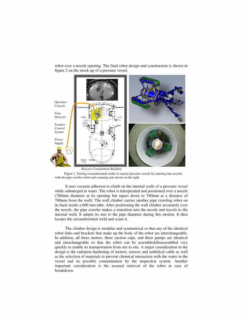
robot over a nozzle opening. The final robot design and construction is shown in
figure 2 on the mock-up of a pressure vessel.
Figure 1. Testing circumferential welds in reactor pressure vessels by entering into nozzles
with the pipe crawler robot and scanning arm shown on the right.
It uses vacuum adhesion to climb on the internal walls of a pressure vessel
while submerged in water. The robot is teleoperated and positioned over a nozzle
(760mm diameter at its opening but tapers down to 540mm at a distance of
700mm from the wall). The wall climber carries another pipe crawling robot on
its back inside a 600 mm tube. After positioning the wall climber accurately over
the nozzle, the pipe crawler makes a transition into the nozzle and travels to the
internal weld. It adapts its size to the pipe diameter during this motion. It then
locates the circumferential weld and scans it.
The climber design is modular and symmetrical so that any of the identical
robot links and brackets that make up the body of the robot are interchangeable.
In addition, all three motors, three suction cups, and three pumps are identical
and interchangeable so that the robot can be assembled/disassembled very
quickly to enable its transportation from site to site. A major consideration in the
design is the radiation hardening of motors, sensors and umbilical cable as well
as the selection of materials to prevent chemical interaction with the water in the
vessel and its possible contamination by the inspection system. Another
important consideration is the assured retrieval of the robot in case of
breakdown.
Reactor Containment Building
Operator
Console
Flaw
Detector
Scanner
Control System
Power
Supply
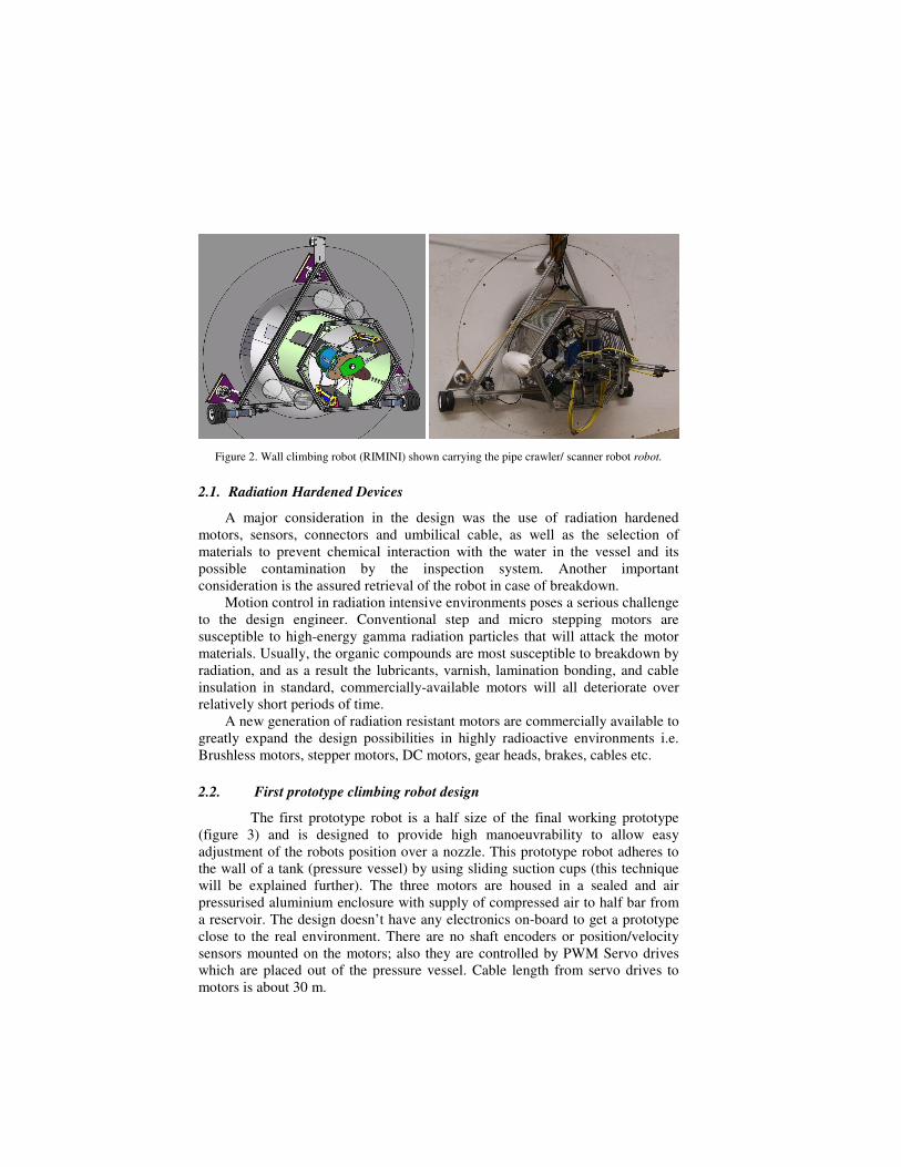
Figure 2. Wall climbing robot (RIMINI) shown carrying the pipe crawler/ scanner robot robot.
2.1. Radiation Hardened Devices
A major consideration in the design was the use of radiation hardened
motors, sensors, connectors and umbilical cable, as well as the selection of
materials to prevent chemical interaction with the water in the vessel and its
possible contamination by the inspection system. Another important
consideration is the assured retrieval of the robot in case of breakdown.
Motion control in radiation intensive environments poses a serious challenge
to the design engineer. Conventional step and micro stepping motors are
susceptible to high-energy gamma radiation particles that will attack the motor
materials. Usually, the organic compounds are most susceptible to breakdown by
radiation, and as a result the lubricants, varnish, lamination bonding, and cable
insulation in standard, commercially-available motors will all deteriorate over
relatively short periods of time.
A new generation of radiation resistant motors are commercially available to
greatly expand the design possibilities in highly radioactive environments i.e.
Brushless motors, stepper motors, DC motors, gear heads, brakes, cables etc.
2.2. First prototype climbing robot design
The first prototype robot is a half size of the final working prototype
(figure 3) and is designed to provide high manoeuvrability to allow easy
adjustment of the robots position over a nozzle. This prototype robot adheres to
the wall of a tank (pressure vessel) by using sliding suction cups (this technique
will be explained further). The three motors are housed in a sealed and air
pressurised aluminium enclosure with supply of compressed air to half bar from
a reservoir. The design doesn’t have any electronics on-board to get a prototype
close to the real environment. There are no shaft encoders or position/velocity
sensors mounted on the motors; also they are controlled by PWM Servo drives
which are placed out of the pressure vessel. Cable length from servo drives to
motors is about 30 m.
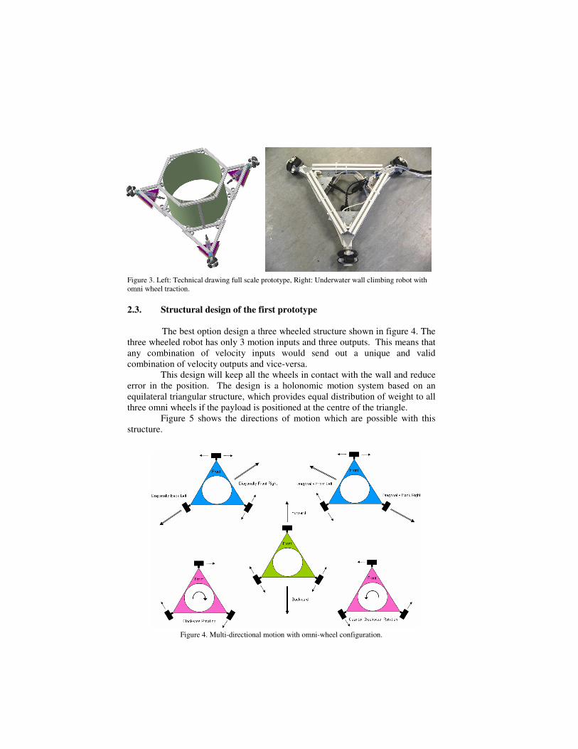
Figure 3. Left: Technical drawing full scale prototype, Right: Underwater wall climbing robot with
omni wheel traction.
2.3. Structural design of the first prototype
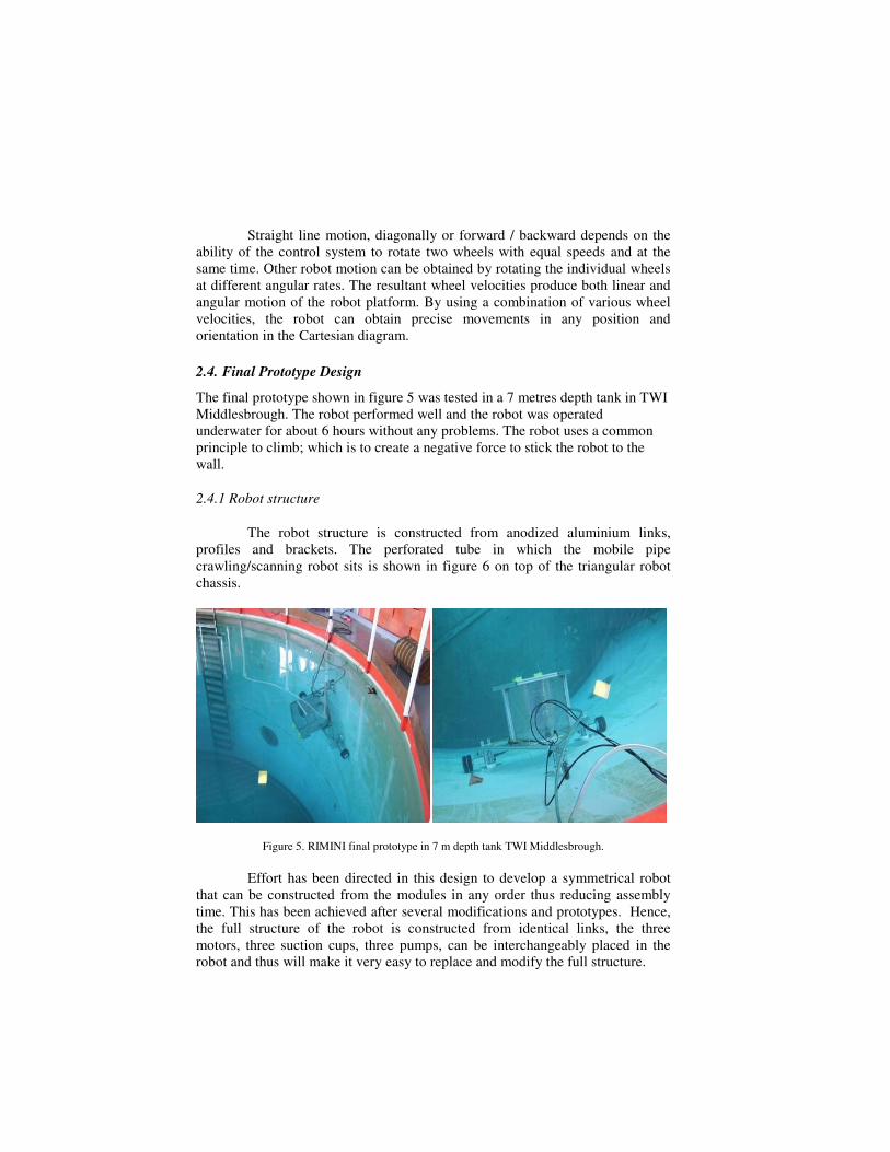
The best option design a three wheeled structure shown in figure 4. The
three wheeled robot has only 3 motion inputs and three outputs. This means that
any combination of velocity inputs would send out a unique and valid
combination of velocity outputs and vice-versa.
This design will keep all the wheels in contact with the wall and reduce
error in the position. The design is a holonomic motion system based on an
equilateral triangular structure, which provides equal distribution of weight to all
three omni wheels if the payload is positioned at the centre of the triangle.
Figure 5 shows the directions of motion which are possible with this
structure.
Figure 4. Multi-directional motion with omni-wheel configuration.
Straight line motion, diagonally or forward / backward depends on the
ability of the control system to rotate two wheels with equal speeds and at the
same time. Other robot motion can be obtained by rotating the individual wheels
at different angular rates. The resultant wheel velocities produce both linear and
angular motion of the robot platform. By using a combination of various wheel
velocities, the robot can obtain precise movements in any position and
orientation in the Cartesian diagram.
2.4. Final Prototype Design
The final prototype shown in figure 5 was tested in a 7 metres depth tank in TWI
Middlesbrough. The robot performed well and the robot was operated
underwater for about 6 hours without any problems. The robot uses a common
principle to climb; which is to create a negative force to stick the robot to the
wall.
2.4.1 Robot structure
The robot structure is constructed from anodized aluminium links,
profiles and brackets. The perforated tube in which the mobile pipe
crawling/scanning robot sits is shown in figure 6 on top of the triangular robot
chassis.
Figure 5. RIMINI final prototype in 7 m depth tank TWI Middlesbrough.
Effort has been directed in this design to develop a symmetrical robot
that can be constructed from the modules in any order thus reducing assembly
time. This has been achieved after several modifications and prototypes. Hence,
the full structure of the robot is constructed from identical links, the three
motors, three suction cups, three pumps, can be interchangeably placed in the
robot and thus will make it very easy to replace and modify the full structure.
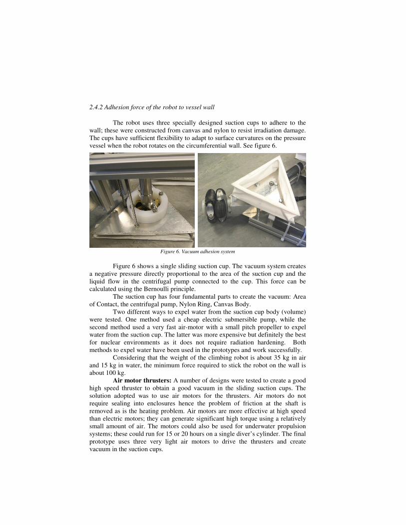
2.4.2 Adhesion force of the robot to vessel wall
The robot uses three specially designed suction cups to adhere to the
wall; these were constructed from canvas and nylon to resist irradiation damage.
The cups have sufficient flexibility to adapt to surface curvatures on the pressure
vessel when the robot rotates on the circumferential wall. See figure 6.
Figure 6. Vacuum adhesion system
Figure 6 shows a single sliding suction cup. The vacuum system creates
a negative pressure directly proportional to the area of the suction cup and the
liquid flow in the centrifugal pump connected to the cup. This force can be
calculated using the Bernoulli principle.
The suction cup has four fundamental parts to create the vacuum: Area
of Contact, the centrifugal pump, Nylon Ring, Canvas Body.
Two different ways to expel water from the suction cup body (volume)
were tested. One method used a cheap electric submersible pump, while the
second method used a very fast air-motor with a small pitch propeller to expel
water from the suction cup. The latter was more expensive but definitely the best
for nuclear environments as it does not require radiation hardening. Both
methods to expel water have been used in the prototypes and work successfully.
Considering that the weight of the climbing robot is about 35 kg in air
and 15 kg in water, the minimum force required to stick the robot on the wall is
about 100 kg.
Air motor thrusters: A number of designs were tested to create a good
high speed thruster to obtain a good vacuum in the sliding suction cups. The
solution adopted was to use air motors for the thrusters. Air motors do not
require sealing into enclosures hence the problem of friction at the shaft is
removed as is the heating problem. Air motors are more effective at high speed
than electric motors; they can generate significant high torque using a relatively
small amount of air. The motors could also be used for underwater propulsion
systems; these could run for 15 or 20 hours on a single diver’s cylinder. The final
prototype uses three very light air motors to drive the thrusters and create
vacuum in the suction cups.
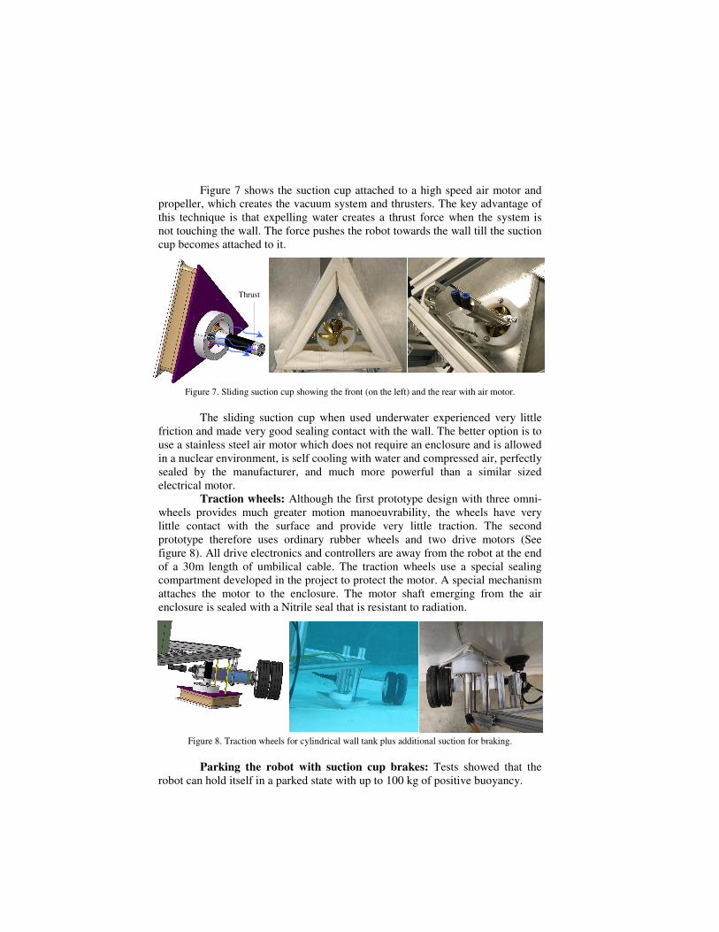
Figure 7 shows the suction cup attached to a high speed air motor and
propeller, which creates the vacuum system and thrusters. The key advantage of
this technique is that expelling water creates a thrust force when the system is
not touching the wall. The force pushes the robot towards the wall till the suction
cup becomes attached to it.
Figure 7. Sliding suction cup showing the front (on the left) and the rear with air motor.
The sliding suction cup when used underwater experienced very little
friction and made very good sealing contact with the wall. The better option is to
use a stainless steel air motor which does not require an enclosure and is allowed
in a nuclear environment, is self cooling with water and compressed air, perfectly
sealed by the manufacturer, and much more powerful than a similar sized
electrical motor.
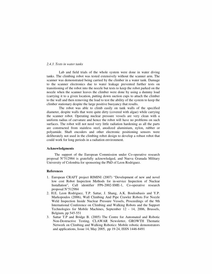
Traction wheels: Although the first prototype design with three omni-
wheels provides much greater motion manoeuvrability, the wheels have very
little contact with the surface and provide very little traction. The second
prototype therefore uses ordinary rubber wheels and two drive motors (See
figure 8). All drive electronics and controllers are away from the robot at the end
of a 30m length of umbilical cable. The traction wheels use a special sealing
compartment developed in the project to protect the motor. A special mechanism
attaches the motor to the enclosure. The motor shaft emerging from the air
enclosure is sealed with a Nitrile seal that is resistant to radiation.
Figure 8. Traction wheels for cylindrical wall tank plus additional suction for braking.
Parking the robot with suction cup brakes: Tests showed that the
robot can hold itself in a parked state with up to 100 kg of positive buoyancy.
Thrust
2.4.3. Tests in water tanks
Lab and field trials of the whole system were done in water diving
tanks. The climbing robot was tested extensively without the scanner arm. The
scanner was demonstrated being carried by the climber in a water tank. Damage
to the scanner electronics due to water leakage prevented further tests on
transitioning of the robot into the nozzle but tests to keep the robot parked on the
nozzle when the scanner leaves the climber were done by using a dummy load
(carrying it to a given location, putting down suction cups to attach the climber
to the wall and then removing the load to test the ability of the system to keep the
climber stationary despite the large positive buoyancy that results.
The robot was able to climb easily on tank walls of the specified
diameter, despite walls that were quite dirty (covered with algae) while carrying
the scanner robot. Operating nuclear pressure vessels are very clean with a
uniform radius of curvature and hence the robot will have no problems on such
surfaces. The robot will not need very little radiation hardening as all the parts
are constructed from stainless steel, anodized aluminium, nylon, rubber or
polyamide. Shaft encoders and other electronic positioning sensors were
deliberately not used in the climbing robot design to develop a robust robot that
could work for long periods in a radiation environment.
Acknowledgments
The support of the European Commission under Co-operative research
proposal N°512984 is gratefully acknowledged, and Nueva Granada Military
University of Colombia for sponsoring the PhD of Leon Rodriguez.
References
1. European CRAFT project RIMINI (2007) “Development of new and novel
low cost Robot Inspection Methods for in-service Inspection of Nuclear
Installation”, Call identifier FP6-2002-SME-1, Co-operative research
proposal N°512984
2. H.E. Leon Rodriguez, T.P. Sattar, J. Shang, A.K. Bouloubasis and Y.P.
Markopoulos (2006), Wall Climbing And Pipe Crawler Robots For Nozzle
Weld Inspection Inside Nuclear Pressure Vessels, Proceedings of the 9th
International Conference on Climbing and Walking Robots and the Support
Technologies for Mobile Machines, September 12 - 14, 2006, Brussels,
Belgium, pp 545-551
3. Sattar T.P and Bridge B. (2005) The Centre for Automated and Robotic
Non-Destructive Testing, CLAWAR Newsletter, GROWTH Thematic
Network on Climbing and Walking Robotics: Mobile robotic demonstrators
and applications, Issue 14, May 2005, pp 19-24, ISSN 1446-8491