UNDERSTANDING TRADITION, MASTERING INNOVATION · UNDERSTANDING TRADITION, MASTERING INNOVATION. 2...
16
Surgical Technique Sports Med Joint Spine UNDERSTANDING TRADITION, MASTERING INNOVATION
Transcript of UNDERSTANDING TRADITION, MASTERING INNOVATION · UNDERSTANDING TRADITION, MASTERING INNOVATION. 2...
Surgical Technique
Sports MedJoint Spine
UNDERSTANDING TRADITION, MASTERING INNOVATION
2
MasterLoc Surgical Technique Sports MedJoint Spine
INTRODUCTION
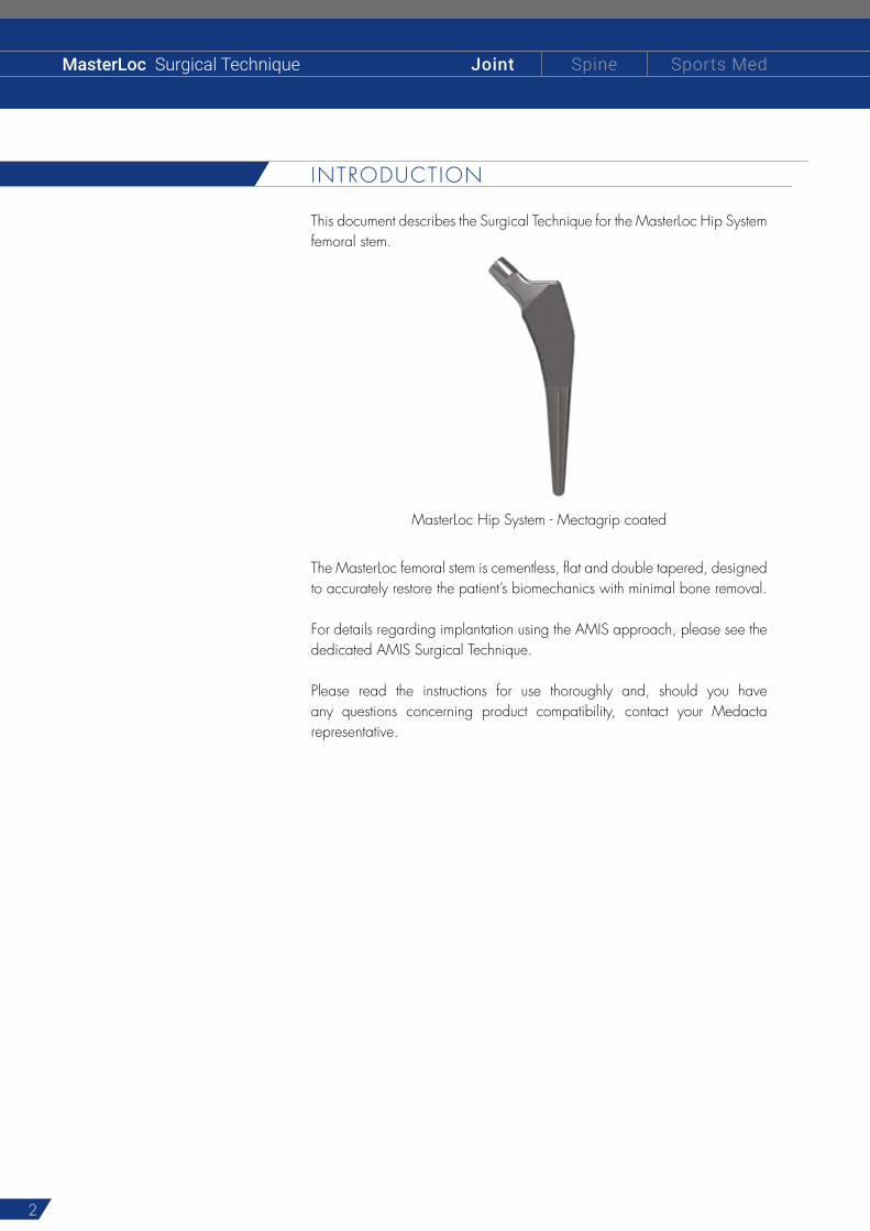
This document describes the Surgical Technique for the MasterLoc Hip System femoral stem.
The MasterLoc femoral stem is cementless, flat and double tapered, designed to accurately restore the patient’s biomechanics with minimal bone removal.
For details regarding implantation using the AMIS approach, please see the dedicated AMIS Surgical Technique.
Please read the instructions for use thoroughly and, should you have any questions concerning product compatibility, contact your Medacta representative.
MasterLoc Hip System - Mectagrip coated
3
1 INDICATIONS OF USE 4
2 CONTRAINDICATIONS 4
3 PREOPERATIVE PLANNING 4
4 SURGICAL APPROACH 5
5 FEMORAL NECK OSTEOTOMY 5
6 FEMORAL PREPARATION 6
7 TRIALING 7
8 FINAL IMPLANTS 9
9 INSTRUMENT DETAILS 11
9.1 Broach assembly 11
9.2 Broach disassembly 12
9.3 Broach handle adjustment (ONLY WHEN STRICTLY NECESSARY) 12
10 IMPLANT NOMENCLATURE 13
11 IMPLANT COMBINATIONS 15
INDEX

4
MasterLoc Surgical Technique Sports MedJoint Spine
PREOPERATIVE PLANNING
Careful preoperative planning is essential. It will help the surgeon to plan for the appropriate implant size in order to recreate as closely as possible the patient’s joint biomechanics. In addition, using the set of X-ray templates to the scale of 1.15:1 (with an X-ray of the same magnification), it will be possible to determine:
The implant size
Appropriate femoral head centre
The level of the neck resection
The MasterLoc Hip System was designed with the goal of maximizing implant fit in the proximal femur. Additionally, the distal geometry of the implant has been reduced compared to traditional flat, tapered wedge implants, enhancing the fit of the implant in the metaphysis while also accommodating those patients who present with Dorr Type A femoral canals.
WARNINGThe final implant will be selected intra-operatively, because of possible discrepancies between actual conditions and templating.
3
1 INDICATIONS OF USE
The MasterLoc stem is designed for use in total or partial hip arthroplasty to provide increased patient mobility and reduce pain by replacing the damaged hip joint, in primary or revision surgery.Total hip arthroplasty is indicated in the following cases:
Severely painful and/or disabled joint as a result of arthrosis, traumatic arthritis, rheumatoid polyarthritis or congenital hip dysplasia
Avascular necrosis of the femoral head
Acute traumatic fracture of the femoral head or neck
Failure of previous hip surgery: joint reconstruction, internal fixation, arthrodesis, partial hip arthroplasty, hip resurfacing replacement or total hip arthroplasty
Partial hip arthroplasty is indicated in the following cases:
Acute traumatic fracture of the femoral head or neck
Non-union of femoral neck fracture
Avascular necrosis of the femoral head
Primary pathology involving the femoral head but with a non deformed acetabulum
2 CONTRAINDICATIONS
Total or partial hip arthroplasty is contraindicated in the following cases:
Acute, systemic or chronic infection
Skeletal immaturity
Severe muscular, neurological, or vascular deficiency, or other pathologies of the affected limb that may compromise the functionality of the implant
Bone condition that may compromise the stability of the implant
Mental or neuromuscular disorders may create an unacceptable risk to the patient and can be a source of postoperative complications.It is the surgeon’s responsibility to ensure that the patient has no known allergy to the materials used.

5
4 SURGICAL APPROACH
5 FEMORAL NECK OSTEOTOMY
The choice of surgical approach is up to the surgeon. The instrumentation has been developed for a conventional approach. Specific instrumentation for the anterior approach is available upon request (for further information see the AMIS dedicated surgical technique).
The level of the neck cut is determined during preoperative planning using the X-ray templates.
The femoral neck osteotomy should be planned in accordance with the anatomy of the patient. The suggested resection angle for this implant is 45° to the diaphyseal axis of the femur. The resection is performed with an oscillating saw, taking care to maintain the planned neck resection.
The femoral head is removed using an extractor.
45°
1.
6
MasterLoc Surgical Technique Sports MedJoint Spine
6 FEMORAL PREPARATIONTo gain access to the medullary canal, the thigh is held in the position that provides the best exposure of the diaphyseal axis, depending on the selected approach.
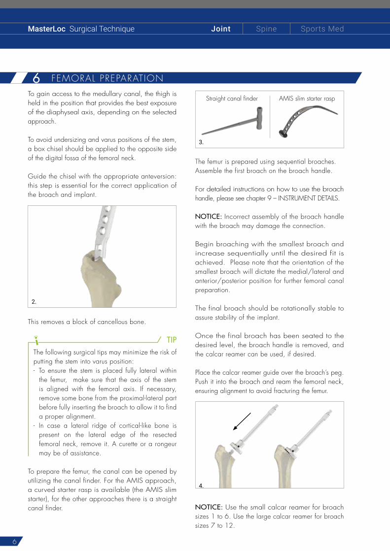
To avoid undersizing and varus positions of the stem, a box chisel should be applied to the opposite side of the digital fossa of the femoral neck.
Guide the chisel with the appropriate anteversion: this step is essential for the correct application of the broach and implant.
2.
This removes a block of cancellous bone.
TIPThe following surgical tips may minimize the risk ofputting the stem into varus position:- To ensure the stem is placed fully lateral within
the femur, make sure that the axis of the stem is aligned with the femoral axis. If necessary, remove some bone from the proximal-lateral part before fully inserting the broach to allow it to find a proper alignment.
- In case a lateral ridge of cortical-like bone is present on the lateral edge of the resected femoral neck, remove it. A curette or a rongeur may be of assistance.
To prepare the femur, the canal can be opened by utilizing the canal finder. For the AMIS approach, a curved starter rasp is available (the AMIS slim starter), for the other approaches there is a straight canal finder.
Straight canal finder AMIS slim starter rasp
3.
The femur is prepared using sequential broaches.Assemble the first broach on the broach handle.
For detailed instructions on how to use the broach handle, please see chapter 9 – INSTRUMENT DETAILS.
NOTICE: Incorrect assembly of the broach handle with the broach may damage the connection.
Begin broaching with the smallest broach and increase sequentially until the desired fit is achieved. Please note that the orientation of the smallest broach will dictate the medial/lateral and anterior/posterior position for further femoral canal preparation.
The final broach should be rotationally stable to assure stability of the implant.
Once the final broach has been seated to the desired level, the broach handle is removed, and the calcar reamer can be used, if desired.
Place the calcar reamer guide over the broach’s peg. Push it into the broach and ream the femoral neck, ensuring alignment to avoid fracturing the femur.
4.
NOTICE: Use the small calcar reamer for broach sizes 1 to 6. Use the large calcar reamer for broach sizes 7 to 12.
7
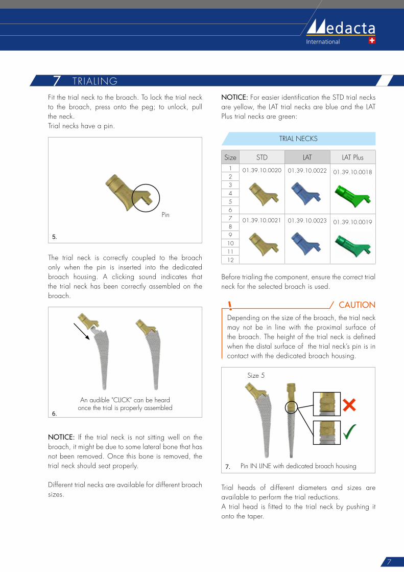
7 TR IAL INGFit the trial neck to the broach. To lock the trial neck to the broach, press onto the peg; to unlock, pull the neck.Trial necks have a pin.
Pin
5.
The trial neck is correctly coupled to the broach only when the pin is inserted into the dedicated broach housing. A clicking sound indicates that the trial neck has been correctly assembled on the broach.
An audible "CLICK" can be heard once the trial is properly assembled
6.
NOTICE: If the trial neck is not sitting well on the broach, it might be due to some lateral bone that has not been removed. Once this bone is removed, the trial neck should seat properly.
Different trial necks are available for different broach sizes.
NOTICE: For easier identification the STD trial necks are yellow, the LAT trial necks are blue and the LAT Plus trial necks are green:
TRIAL NECKS
Size STD LAT LAT Plus1 01.39.10.0020 01.39.10.0022 01.39.10.0018234567 01.39.10.0021 01.39.10.0023 01.39.10.001989
101112
Before trialing the component, ensure the correct trial neck for the selected broach is used.
CAUTIONDepending on the size of the broach, the trial neck may not be in line with the proximal surface of the broach. The height of the trial neck is defined when the distal surface of the trial neck’s pin is in contact with the dedicated broach housing.
Pin IN LINE with dedicated broach housing
Size 5
7.
Trial heads of different diameters and sizes are available to perform the trial reductions.A trial head is fitted to the trial neck by pushing it onto the taper.
8
MasterLoc Surgical Technique Sports MedJoint Spine
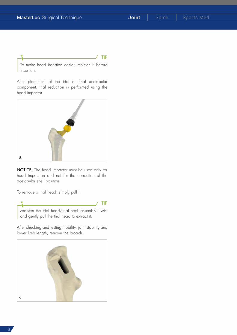
TIPTo make head insertion easier, moisten it before insertion.
After placement of the trial or final acetabular component, trial reduction is performed using the head impactor.
8.
NOTICE: The head impactor must be used only for head impaction and not for the correction of the acetabular shell position.
To remove a trial head, simply pull it.
TIPMoisten the trial head/trial neck assembly. Twist and gently pull the trial head to extract it.
After checking and testing mobility, joint stability and lower limb length, remove the broach.
9.
9
8 F INAL IMPLANTSInsert the final prosthesis into place. The final prosthesis size corresponds to the size of the last broach.
WARNINGTake care not to damage the taper’s micro-thread when positioning the final implant.
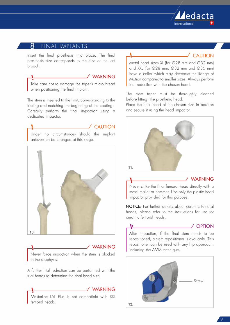
The stem is inserted to the limit, corresponding to the trialing and matching the beginning of the coating.Carefully perform the final impaction using a dedicated impactor.
CAUTIONUnder no circumstances should the implant anteversion be changed at this stage.
10.
WARNINGNever force impaction when the stem is blocked in the diaphysis.
A further trial reduction can be performed with the trial heads to determine the final head size.
WARNINGMasterLoc LAT Plus is not compatible with XXL femoral heads.
CAUTIONMetal head sizes XL (for Ø28 mm and Ø32 mm) and XXL (for Ø28 mm, Ø32 mm and Ø36 mm) have a collar which may decrease the Range of Motion compared to smaller sizes. Always perform trial reduction with the chosen head.
The stem taper must be thoroughly cleaned before fitting the prosthetic head. Place the final head of the chosen size in position and secure it using the head impactor.
11.
WARNINGNever strike the final femoral head directly with a metal mallet or hammer. Use only the plastic head impactor provided for this purpose.
NOTICE: For further details about ceramic femoral heads, please refer to the instructions for use for ceramic femoral heads.
OPTIONAfter impaction, if the final stem needs to be repositioned, a stem repositioner is available. This repositioner can be used with any hip approach, including the AMIS technique.
Screw
12.

10
MasterLoc Surgical Technique Sports MedJoint Spine
Assemble the stem repositioner by unscrewing the screw with the 3.5mm screwdriver to open the plastic clamps. Then, assemble it to the implanted stem until this is firmly seated between the plastic clamps and re-tighten the screw. The metal body should be positioned on the medial side of the stem.
13.
Depending on the selected approach, screw the threaded stem extractor M8 onto the stem repositioner (30° hole is suggested for the AMIS approach). Pull out the stem.
30°
0°
14.
11
9 INSTRUMENT DETAILS
Reference Description
01.36.10.0070 AMIS Pincer broach handle
01.36.10.0073 Pincer broach handle
01.39.10.0024 Straight pincer broach handle
01.10.10.198 Offset 30° pincer broach handle RIGHT
01.10.10.199 Offset 30° pincer broach handle LEFT
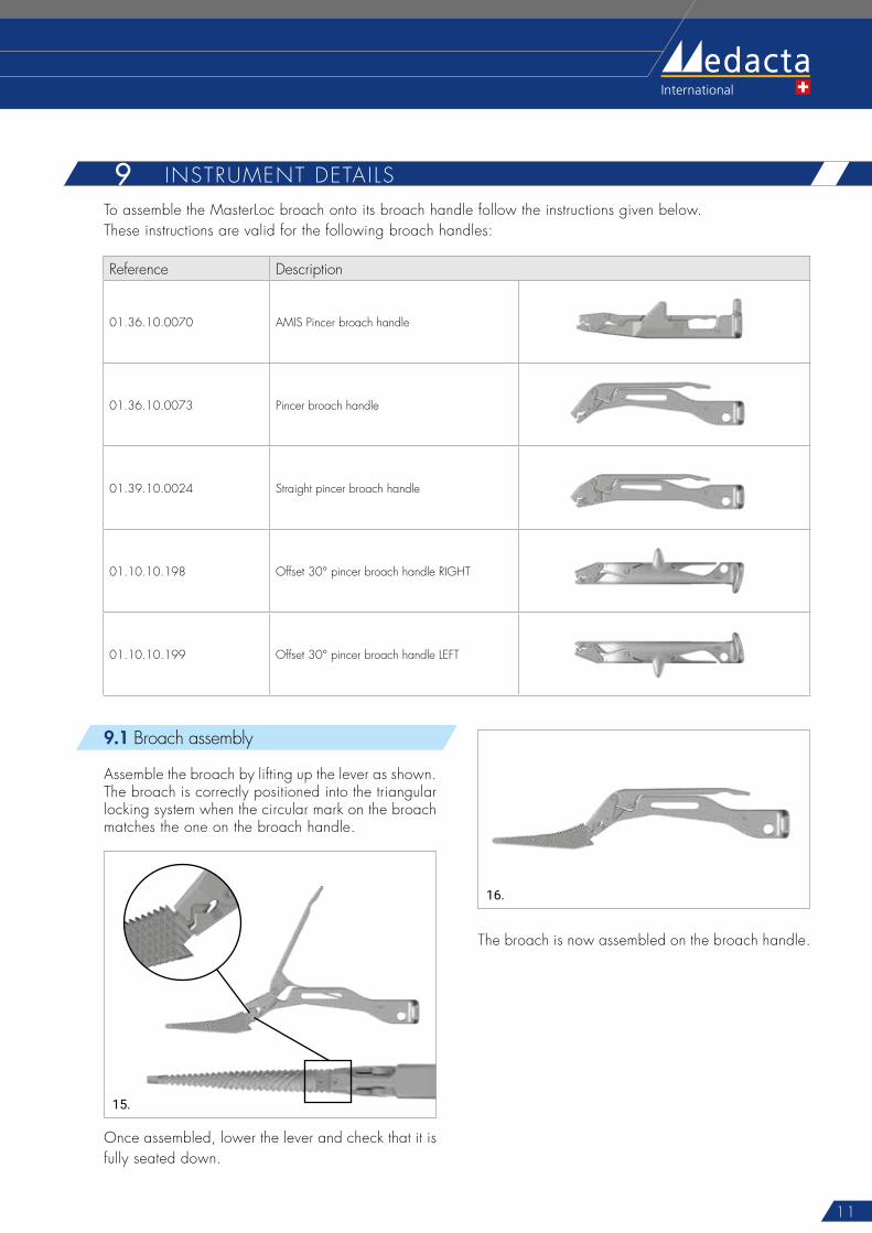
To assemble the MasterLoc broach onto its broach handle follow the instructions given below.These instructions are valid for the following broach handles:
9.1 Broach assembly
Assemble the broach by lifting up the lever as shown. The broach is correctly positioned into the triangular locking system when the circular mark on the broach matches the one on the broach handle.
15.
Once assembled, lower the lever and check that it is fully seated down.
16.
The broach is now assembled on the broach handle.
12
MasterLoc Surgical Technique Sports MedJoint Spine
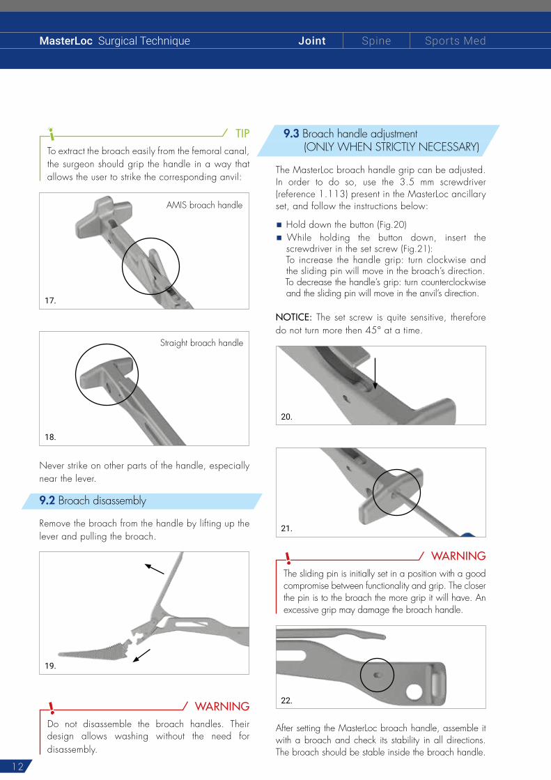
TIPTo extract the broach easily from the femoral canal, the surgeon should grip the handle in a way that allows the user to strike the corresponding anvil:
AMIS broach handle
17.
Straight broach handle
18.
Never strike on other parts of the handle, especially near the lever.
9.2 Broach disassembly
Remove the broach from the handle by lifting up the lever and pulling the broach.
19.
WARNINGDo not disassemble the broach handles. Their design allows washing without the need for disassembly.
9.3 Broach handle adjustment (ONLY WHEN STRICTLY NECESSARY)
The MasterLoc broach handle grip can be adjusted.In order to do so, use the 3.5 mm screwdriver (reference 1.113) present in the MasterLoc ancillary set, and follow the instructions below:
Hold down the button (Fig.20)
While holding the button down, insert the screwdriver in the set screw (Fig.21):
To increase the handle grip: turn clockwise and the sliding pin will move in the broach’s direction.
To decrease the handle’s grip: turn counterclockwise and the sliding pin will move in the anvil’s direction.
NOTICE: The set screw is quite sensitive, therefore do not turn more then 45° at a time.
20.
21.
WARNINGThe sliding pin is initially set in a position with a good compromise between functionality and grip. The closer the pin is to the broach the more grip it will have. An excessive grip may damage the broach handle.
22.
After setting the MasterLoc broach handle, assemble it with a broach and check its stability in all directions. The broach should be stable inside the broach handle.
13
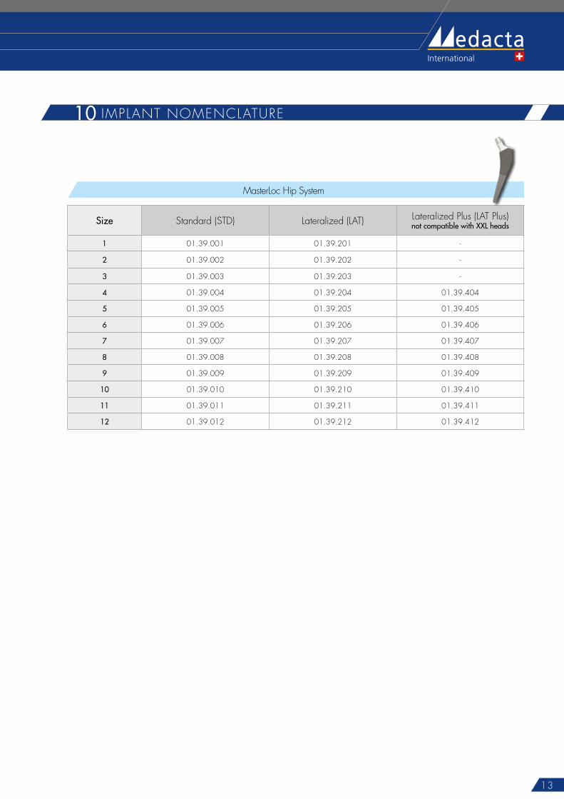
10 IMPLANT NOMENCLATURE
MasterLoc Hip System
Size Standard (STD) Lateralized (LAT) Lateralized Plus (LAT Plus)not compatible with XXL heads
1 01.39.001 01.39.201 -
2 01.39.002 01.39.202 -
3 01.39.003 01.39.203 -
4 01.39.004 01.39.204 01.39.404
5 01.39.005 01.39.205 01.39.405
6 01.39.006 01.39.206 01.39.406
7 01.39.007 01.39.207 01.39.407
8 01.39.008 01.39.208 01.39.408
9 01.39.009 01.39.209 01.39.409
10 01.39.010 01.39.210 01.39.410
11 01.39.011 01.39.211 01.39.411
12 01.39.012 01.39.212 01.39.412
14
MasterLoc Surgical Technique Sports MedJoint Spine
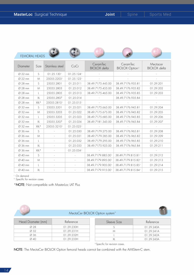
FEMORAL HEADS
Diameter Size Stainless steel CoCr CeramTecBIOLOX delta
CeramTec BIOLOX Option II
Mectacer BIOLOX delta
Ø 22 mm S 01.25.130 I 01.25.124 I - - -
Ø 22 mm M 25055.2203 I 01.25.123 I - - -
Ø 28 mm S 25055.2801 01.25.011 38.49.7175.445.00 38.49.7176.935.81 01.29.201
Ø 28 mm M 25055.2803 01.25.012 38.49.7175.455.00 38.49.7176.935.82 01.29.202
Ø 28 mm L 25055.2805 01.25.013 38.49.7175.465.00 38.49.7176.935.85 01.29.203
Ø 28 mm XL 25055.2807 01.25.014 - 38.49.7176.935.84 -
Ø 28 mm XXL* 25055.2810 I 01.25.015 I - - -
Ø 32 mm S 25055.3201 01.25.021 38.49.7175.665.00 38.49.7176.945.81 01.29.204
Ø 32 mm M 25055.3203 01.25.022 38.49.7175.675.00 38.49.7176.945.82 01.29.205
Ø 32 mm L 25055.3205 01.25.023 38.49.7175.685.00 38.49.7176.945.85 01.29.206
Ø 32 mm XL 25055.3207 01.25.024 38.49.7181.345.00 38.49.7176.945.84 01.29.207
Ø 32 mm XXL* 25055.3210 I 01.25.025 I - - -
Ø 36 mm S - 01.25.030 38.49.7179.275.00 38.49.7176.965.81 01.29.208
Ø 36 mm M - 01.25.031 38.49.7179.285.00 38.49.7176.965.82 01.29.209
Ø 36 mm L - 01.25.032 38.49.7179.295.00 38.49.7176.965.85 01.29.210
Ø 36 mm XL - 01.25.033 38.49.7175.925.00 38.49.7176.965.84 01.29.211
Ø 36 mm XXL* - 01.25.034 I - - -
Ø 40 mm S - - 38.49.7179.885.00 I 38.49.7179.815.81 I 01.29.212
Ø 40 mm M - - 38.49.7179.895.00 I 38.49.7179.815.82 I 01.29.213
Ø 40 mm L - - 38.49.7179.905.00 I 38.49.7179.815.85 I 01.29.214
Ø 40 mm XL - - 38.49.7179.915.00 I 38.49.7179.815.84 I 01.29.215
I On demandII Specific for revision cases
Head Diameter (mm) ReferenceØ 28 01.29.230HØ 32 01.29.231HØ 36 01.29.232HØ 40 01.29.233H
Sleeve Size ReferenceS 01.29.240AM 01.29.241AL 01.29.242AXL 01.29.243A
MectaCer BIOLOX Option system''
II Specific for revision cases.
NOTE: The MectaCer BIOLOX Option femoral heads cannot be combined with the AMIStem-C stem.
*NOTE: Not compatible with MasterLoc LAT Plus
15
The instrumentation is not sterile upon delivery. It must be cleaned before use and sterilised in an autoclave in accordance with the regulations of the country, EU directives where applicable and following the instructions for use of the autoclave manufacturer. For detailed instructions please refer to the document “Recommendations for cleaning decontamination and sterilisation of Medacta International orthopaedic devices” available at www.medacta.com.
N O T E F O R S T E R I L I S A T I O N
Part numbers subject to change.
All Medacta implant combinations are represented in the table "Medacta Hip product compatibility" (réf. 99.99.COM) available at www.medacta.com.
NOTICE: in the case of a Ceramic-on-Ceramic bearing it is compulsory to use compatible ceramic femoral heads and liners.
11 IMPLANT COMBINATIONS

MasterLocSurgical Technique
ref: 99.73.12rev. 06
Last update: February 2018 0476
Medacta International SAStrada Regina - 6874 Castel San Pietro - SwitzerlandPhone +41 91 696 60 60 - Fax +41 91 696 60 [email protected]
Find your local dealer at: medacta.com/locations
All trademarks and registered trademarks are the property of their respective owners.