Analytical Modeling of Surface and Subsurface Initiated Fretting Wear

Understanding the fretting wear of Ti3SiC2
Debasish Sarkar, B.V. Manoj Kumar, Bikramjit Basu∗
Laboratory for Advanced Ceramics, Department of Materials and Metallurgical Engineering,Indian Institute of Technology, Kanpur 208016, India
Abstract
The objective of the present research is to understand the tribological properties of Ti3SiC2. The fretting wear experiments were conducted onhot pressed Ti3SiC2 against bearing steel under varying load (1–10 N). Under selected fretting conditions, Ti3SiC2/steel couple exhibits higherCOF of 0.5–0.6. Based on the detailed AFM analysis of the worn surface, the roughness parameters and bearing area of the worn surfaces arealso evaluated. SEM–EDS analysis indicates the mutual material transfer between the counterfaces at the fretted contacts. Raman spectroscopyreveals that the fretting wear is accompanied by triboxidation with the formation of TiO2, SiO2 and Fe2O3. An important observation is that‘metal-like plasticity’ behavior is observed on worn TiSiC at higher load (>6 N). A probable explanation for the transition in friction andw
K
1
brBolTbbwITaTt
r
lowm
ace
alongringr coor-
arycon-the
Ti
ittle-lndi--cally
3 2
ear with load is proposed.
eyword: Friction; Wear resistance; Electron microscopy; Spectroscopy; Plasticity
. Introduction
Since the discovery of a vast number of ternary car-ides and nitrides by Jeitschko and Nowotny,1 Ti3SiC2 haseceived attention in the materials community.2–12Recently,arsoum2 identified that these phases represent a new classf solids that can be described as thermodynamically stable
aminates. These exhibit both metallic and ceramic features.2
his class of materials was lately named as MAX phases,ecause of their chemistry: ternary layered hexagonal car-ides and nitrides, with the general formula Mn+ 1AXn,heren= 1–3, M is an early transition metal, A belonging to
II–VIA group of periodic table and X is either C and/or N.he physical properties (thermal and electrical conductivity)nd mechanical behavior of ternary carbides, in particulari3SiC2 have been investigated with a focus to understand
he structure–property correlation.Some of the key properties of Ti3SiC2 include excellent
esistance to oxidation up to 1400◦C, high thermal shock
∗ Corresponding author. Tel.: +91 512 2597771; fax: +91 512 2597505.
resistance, high Young’s modulus (325 GPa), relativelyhardness (4–5 GPa), high fracture toughness (7–9 MPa1/2)and good machinability with conventional tools.6,7 Likegraphite, Ti3SiC2 has a hexagonal structure with a spgroup ofP63/mmc. The crystal structure of Ti3SiC2, as shownin Fig. 1, can be described as a planar stacking sequencethec-axis, consisting of double layers of Ti–C edge-shaoctahedra, sandwiched between sheets of square-planadinated Si atoms.1 The electrical ((2–15)× 106 �−1 m−1)and thermal (20–50 W/m K) conductivities of these terncarbides exceed those of Ti metal. The high electricalductivity is attributed to the metallic bonding parallel tobasal plane.5 Being readily machinable, Ti3SiC2 is elasti-cally quite stiff (∼320 GPa), i.e. three times stiffer thanmetal, however, with the same density as Ti, i.e.∼4.5 gm/cc.8
Ti3SiC2 is also a damage-tolerant material and has a brto-ductile transition at 1200◦C. At 1300◦C, the materiaexhibits “yield” points at 100 and 500 MPa in flexure acompression loading, respectively.9 The large-grained, orented, polycrystalline form of Ti3SiC2, loaded in compression at room temperature, was reported to deform plasti
E-mail address:[email protected] (B. Basu). by a combination of shear and kink-band formation.3,4

Fig. 1. Unit cell of Ti3SiC2.1
From the perspective of engineering applications, the fric-tional and the sliding wear resistance of Ti3SiC2 was eval-uated to a limited extent. Myhra et al.,10 using lateral forcemicroscopy, measured a low kinetic friction coefficient (µ)of 0.002–0.005 at 1000–20000 nN normal force for the basalplanes of Ti3SiC2. They also reported thatµ for a poly-crystalline Ti3SiC2, against a lightly peened stainless steelsheet, under a load of 0.15–0.9 N is∼0.12. Barsoum andco-workers reported a high coefficient of friction (COF) of0.8 for a Ti3SiC2/steel tribocouple at 5 N load.11 In theirstudy, the frictional characteristics, as measured using pin-on-disc, were found to be independent of the microstructureof Ti3SiC2 (grain size varied between 5 and 100�m). Zhanget al.12 investigated the friction and wear behavior of self-mated Ti3SiC2 tribocouple and Ti3SiC2/diamond pairs usingpin-on-flat tribometer. The friction coefficient of the formeris 1.16–1.43, but that of the latter is below 0.1 for vary-ing loads of 0.49–9.8 N load. The low friction coefficientof Ti3SiC2 against diamond was attributed to the formationof a lubricating film on the Ti3SiC2 tribosurface. In a recentreport, Tang et al.13 reported that laser melted ternary metalsilicide, Cr13Ni5Si2 alloy could exhibit excellent wear resis-tance compared to hardened 0.45% C steel and 1.0% C–1.5%Cr containing tool steel under sliding wear conditions at98–196 N load, measured on a ball-on-wheel tribometer.
Although the above research findings briefly report thef -i rriedo m ofT toi the
dominant wear mechanisms involved during small amplitudeof vibration (fretting) with varying load. This was the majormotivation for the present work.
2. Experimental
2.1. Materials
The flat materials for tribological testing were Ti3SiC2,which were obtained as hot pressed discs. The green com-pacts containing appropriate stoichiometric amounts of com-mercial TiC0.67and Si (−325 mesh, 99.99%) are hot pressedin graphite die at 1420◦C for 90 min under Ar atmosphereat 25 MPa pressure to obtain the final density of 98–99%ρth. The larger disk specimens were machined to disks of15 mm in diameter and 3 mm in thickness. The test surface ofthe disks was smoothly polished down to∼0.15�m surfacefinish by wet abrasive polishing with finishing polish by dia-mond paste. Based on the Archimedes principle, the densityof the sintered specimens was measured using water. Univer-sal hardness tester was used to evaluate the Vickers hardness(Hv10) of the composite with 10 kg load. The reported valueis the average of data obtained from five indentation tests. Thefracture toughness (KIC) was determined by single-edged pre-c ach.T lumeH lec-t
likee( st)i oint-c ted
Fs lla
rictional properties of Ti3SiC2, no detailed work, accordng to the best of the author’s knowledge, has been caut to comprehensively understand the wear mechanisi3SiC2. Against the above backdrop, it will be interesting
nvestigate the friction and wear behavior and to identify
racked beam (SEPB) method using the V-notch approhe polished samples were etched using a 1:1:1 by voF:HNO3:H2O solution and observed under scanning e
ron microscopy.The Ti3SiC2 microstructure is characterized by plate
longated grain (∼50–200�m) with an aspect ratio of∼8seeFig. 2). The unreacted fraction of TiC (bright contras dispersed throughout the matrix. Based on the pount method, the volume fraction of TiC in the investiga
ig. 2. SEM image of Ti3SiC2, etched in a 1:1:1 by volume HF:HNO3:H2Oolution. Note the presence of large elongated Ti3SiC2 grains and the smamount of TiC (bright contrast).

3
Table 1The density and mechanical properties of the tribocouple used in our experiment
Specimen Material Density,ρ (gm/cc) Hardness (GPa) E (GPa) Fracture toughness,KIC (MPa m1/2)
Flat Ti3SiC2 (T1) 4.5 4.7± 0.3 316 8.9± 0.1Ball (counterbody) Steel (SAE 52100 Grade) 7.8 ∼7.0 210 –
Ti3SiC2 is measured to be 13.6. X-ray diffraction analysisalso confirmed the predominant presence of Ti3SiC2 witha small amount of TiC. The density of the Ti3SiC2 flatsample was found to be 4.5 gm/cc, while that of steel ballwas 7.8 gm/cc (seeTable 1). The investigated polycrystallineTi3SiC2 has a combination of moderate hardness (∼5 GPa),lower than hardened steel (∼7 GPa), and good fracture tough-ness (∼9 MPa m1/2), better than many structural ceramics(2–5 MPa m1/2).
2.2. Wear tests and characterization of the surface
Based on our conceptual design and requirements, a ball-on-disk type fretting tribometer has recently been fabricatedand installed in our laboratory (seeFig. 3a). Fretting is definedas small amplitude linear relative tangential sliding at con-stant normal load.14,15 The computerized fretting tester hastwo transducers: an inductive displacement transducer sens-ing the movement of the flat sample and a piezoelectric trans-ducer attached to the loading arm, monitors friction force.The friction coefficient is obtained from the on-line measuredtangential force. Ti3SiC2 was used as a flat sample, whichoscillates over the desired displacement. The commercialbearing SAE 52100 grade steel balls (hardness 63–65 HRc,data from supplier) of 8 mm in diameter were used as coun-terbody (stationary). This detail of the fretting set up can bef ornm c-i Thef ads
(1–10 N) with constant testing duration, at constant frequency(8 Hz) and constant displacement stroke (100�m). All testswere done in air at room temperature (28± 2◦C) with rela-tive humidity (RH) 50± 5%. The schematic of the frettingcontact is shown inFig. 3b. The combination of mode I fret-ting parameters results in gross slip sliding between matingsurfaces across the whole contact area under the selectedexperimental conditions.
After each test, the worn surfaces of both the flat andthe ball were ultrasonically cleaned with acetone. The wearscar profiles on each Ti3SiC2 sample were obtained usinga computer-controlled laser surface profilometer (Mahr-Perthometer PGK 120). IR light (780 nm) is focused onto thewear scar and the reflected light from the surface is directed toa detector. With the help of a transducer, the moving positionof the light is converted to an electrical signal, which is furtherprocessed to generate the 3D profile of the worn surface. Thewear volume is calculated by integrating the surface area ofeach 2D profile (extracted from different locations on 3D pro-file) over distance. From the estimated wear volume, the spe-cific wear rates [wear volume/(load× total fretted distance)]are calculated. Further detailed characterization of the wornsurfaces was performed using a scanning electron micro-scope (FEI QUANTA 2000 HV SEM) equipped with energydispersive X-ray analysis (EDX). The Raman spectrometer(Spectra Physics, 1877E Triplemate, USA), equipped witha rgoni tudyt rdedi 0 s.
F tigationl les—n
ound elsewhere.16 The mechanical properties of the unwaterials are presented inTable 1. Before each test, the spe
men and ball were ultrasonically cleaned with acetone.retting wear experiments were carried out with varying lo
ig. 3. A newly designed fretting set-up (a) used in the present invesength, 100�m; oscillation frequency, 8 Hz and cycles 100,000. Variab
nitrogen cooled charge coupled device (CCD) and aon laser with a wavelength of 514.52 nm, was used to she chemistry of the tribolayer. Raman spectra were recon the extended scan mode with acquisition time of 30
. Schematic of the fretting contact (b). The testing conditions: constants—Strokeormal load (P: 2–10 N).

The major structural phases were identified using the litera-ture reports.17–18The worn surface was also studied with anatomic force microscope (AFM, Molecular Imaging, Pico-SPM I, USA) using ‘contact mode’. A Si3N4 cantilever witha three-sided pyramidal single crystal Si3N4 tip with apexangle of 20◦, a tip radius of curvature of 10 nm and a normalstiffness of∼0.6 N/m were employed. To obtain the surfacetopography, typically an area of 1�m× 1�m of the wornsurfaces after testing at 6 and 8 N were scanned with a fre-quency of 55 Hz and a speed of 2.2�m/s. This technique isparticularly useful to determine the surface topography andthe roughness parameters of the worn surfaces.
3. Results
3.1. Friction behavior
Fig. 4shows the plot for the frictional behavior of Ti3SiC2fretted against steel with varying load. FromFig. 4, it is clearthat the evolution of frictional behavior is strongly depen-dent on normal load as well as fretting cycles. During therunning-in-period, the initial surface asperities of flat andball get continuously knocked off and coefficient of fric-tion (COF) increases to a high value during the first 6000,1500 and 1000 cycles under 1, 6 and 8 N load, respectively.T stateC . Ath e as∼ sm t 5 Nl se, isp pin-o tingp the
Fc
Fig. 5. The measured wear rate and coefficient of friction (µ), obtained whenTi3SiC2 is fretted against steel under varying loads for 100,000 cycles.
investigated tribocouple will be discussed in more details inSection4.
3.2. Wear behavior
3.2.1. Wear dataThe wear volume, measured using laser surface profilome-
ter, is normalized with respect to normal load and total slid-ing distance (number of cycles× displacement stroke× 2)to obtain the specific wear rate of Ti3SiC2, which is plot-ted against load inFig. 5. Observing the data inFig. 5, itis clear that wear rate varies over the same order of mag-nitude, i.e. 10−5 mm3/N m. At the lowest load regime (1 N),the specific wear rate is low and around 10× 10−5 mm3/N m.The wear rate is observed to increase with load from 1 to2 N, but does not vary much ((20–25)× 10−5 mm3/N m) forfretting load of 2–6 N. However, a significant increase inwear rate is observed at 8 and 10 N load with a maximumof ∼37× 10−5 mm3/N m recorded at 8 N load. It is interest-ing to note that the wear rate of hard ceramics like Al2O3,SiC and Si3N4 is measured in the order of 10−6 mm3/N m(lowest up to 10−9 mm3/N m).19–21The higher wear rate ofTi3SiC2 is presumably due to lower hardness (∼4–5 GPa).Furthermore, it can be noted that even much higher wear rateof 10−3 mm3/N m is recorded for Ti3SiC2 against steel usingpin-on-disk tribometer.11
3orn
si ity off singl ledi dica-t age.T SEMi
hen, the coefficient of friction decreased to a steadyOF of∼0.55 and 0.62 at load 1 and 6 N, respectivelyigh load (8 N), the steady state COF is observed to b0.5. It can be noted here that the COF of Ti3SiC2/steel, aeasured by pin-on-disk tribometer, lies around 0.83 a
oad.11 The lower COF, as measured in the present caresumably due to difference in contact configuration (n-disk sliding versus ball-on-flat fretting) and operaarameters (sliding velocity). The frictional behavior of
ig. 4. Friction characteristics under different load for Ti3SiC2/steel frettingouple.
.2.2. SEM observationsSEM images revealing the overall topography of the w
urfaces, both on flat and ball are presented inFig. 6. Look-ng at the fretted area on flats, it is evident that the severretting induced material damage increases with increaoad, with maximum wear at 8 N load. This is also reveaf one compares the transverse wear scar diameter, an inive parameter to characterize the intensity of wear damhe transverse wear scar diameter, as measured from
mages, is∼200�m at 1 N load and increases to∼330�m at

Fig. 6. SEM images revealing the overall topography of fretted zone on Ti3SiC2 flat (a–d) as well as steel counterbody (e and f), after fretting tests for 100,000cycles at varying loads, as mentioned in individual figure. The pointed arrow indicates the sliding direction.

Fig. 7. SEM images showing deeper abrasive scratches of groove width around 2–3�m (a), spalling of non-protective tribochemical layer due to propagation ofcracks (b and c) on Ti3SiC2 worn surface after fretting against bearing steel for 100,000 cycles under varying loads, as mentioned against individual micrograph.EDS analysis indicating a small amount of Fe transfer from steel ball (d). The difference in contrast of debris particle or transfer layer with the wornbasematerial indicates the difference in chemistry. The pointed arrow indicates the sliding direction.
6 N load. At higher loads of 8 and 10 N, the transverse wearscar diameter is maximum and around 500–510�m.
Before we discuss the mechanisms of material removalfrom tribosurfaces, it is imperative to define abrasion andtribochemical wear. When the surface asperities (irregularperturbances of surface profile) from harder mating solid slideon a softer surface, the deformation or ploughing induceddamage experienced by softer material is known as abrasion.When the contact is established between two mating solids,it is known as two-body abrasion. Alternatively, if the weardebris particles, generated during initial sliding, abrade thesofter of the mating solids, then it is known as three-bodyabrasion. Tribochemical wear is usually defined as materialremoval process due to the chemical reactions either betweena sliding body with the surrounding environment or betweentwo moving solids, which lead to the formation of a distincttribolayer. The chemical reactions are triggered at tribologi-cal contacts due to frictional energy. The friction and wear,in the presence of tribochemical layer largely depends on thestability or properties of the layer itself.
In the present investigation, macroscopically, it isobserved that abrasion largely contributes to wear of Ti3SiC2surfaces at lower loads (≤6 N). At higher loads (≥8 N), theformation of tribochemical layer and severe spalling of tribo-layer is critically observed (Fig. 6c and d). While observingthe fretted zone on steel counterbody, it is noted that the trans-verse wear scar diameter is around 150�m at 1 N load andremains same at 6 N load (Fig. 6e and f). Also at the low-est load, the damage of steel ball appears to be more at thecentral region of the fretting scar, while other areas of scardo not exhibit any noticeable damage. At 6 N load, the tribo-chemical layer adheres on steel ball on a larger area of wearscar, compared to that at 1 N load. From the above observa-tion, it is evident that the wear of steel ball is less compared toTi3SiC2 flat, which can be expected from the hardness values(seeTable 1).
Detailed topographical features of the worn surfaces afterfretting at low load regime (1–6 N) are presented inFig. 7.It is important to note that the deeper abrasive scratches ofgroove width around 2–3�m are observed even at the lowest

Fig. 8. SEM images showing extensive plastic deformation (a and d), EDS analysis revealing significant transfer of steel debris (b), cracks propagatingalong the edges of elongated grains (c) on the fretted surface of Ti3SiC2 after fretting against steel, for 100,000 cycles at high loads of 8 and 10 N, indi-cated in individual SEM image. The details of the deformed tribolayer are also shown in the inset of (a and d). The pointed arrow indicates the slidingdirection.
load of 1 N. The presence of transfer layer and wear debrisparticles (brighter contrast) are found to adhere on the abra-sive scratches (Fig. 7a). The formation of tribochemical layeris significant at 4 N load, as revealed inFig. 7b. However, thetribochemical layer is non-protective and spalls off due topropagation of cracks, primarily in the direction perpendicu-lar to the fretting motion. Observing the difference in electroncontrast between base worn material and the tribochemicallayer, it is clear that the chemistry of the later is much differ-ent from the former. Also, at 6 N load, plastically deformedlayer can be observed which also contributes to the materialremoval (Fig. 7c). EDS analysis (Fig. 7d) reveals a smalleramount of transferred Fe from steel ball.
A clear change in worn surface topography is noted athigher loads of 8 and 10 N (seeFig. 8). The evidence ofextensive plastic deformation is clear at 8 N load (Fig. 8a)and the topographical features are more like that of wornsurface, commonly observed with metallic materials. The
fracture of elongated Ti3SiC2 grains on the fretted surfaceis also observed and the cracks are found to propagate alongthe edges of elongated grains. A closer observation ofFig. 8creveals that the fracture process aids in generation of coarserdebris particles with size in the range of 5–30�m. EDS anal-ysis (Fig. 8b) reveals an increased transfer of steel debris at8 N load and the transfer of steel debris particle appeared inbright contrast, as seen inFig. 8c. At the highest load of 10 N,the contribution of plastic deformation is equally significantand the presence of cracks is also observed (Fig. 8d).
Extensive wear of steel ball is also observed, as shownin Fig. 9. At 1 N load, the severity of abrasion as well asthe transfer layer with difference in compositional contrastis noted in back scattered electron (BSE) image, as shownin Fig. 9a. At the highest load of 10 N, the wear of steel ballis dominated by abrasion as well as formation of transferlayer (Fig. 9b). The compositional analysis of the worn sur-face using EDS reveals some interesting information. Mutual
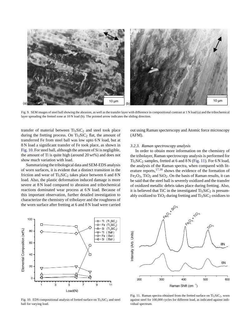
Fig. 9. SEM images of steel ball showing the abrasion, as well as the transfer layer with difference in compositional contrast at 1 N load (a) and the tribochemicallayer spreading the fretted zone at 10 N load (b). The pointed arrow indicates the sliding direction.
transfer of material between Ti3SiC2 and steel took placeduring the fretting process. On Ti3SiC2 flat, the amount oftransferred Fe from steel ball was low upto 6 N load, but at8 N load a significant transfer of Fe took place, as shown inFig. 10. For steel ball, although the amount of Si is negligible,the amount of Ti is quite high (around 20 wt%) and does notshow much variation with load.
Summarizing the tribological data and SEM-EDS analysisof worn surfaces, it is evident that a distinct transition in thefriction and wear of Ti3SiC2 takes place between 6 and 8 Nload. Also, the plastic deformation induced damage is moresevere at 8 N load compared to abrasion and tribochemicalreactions dominated wear process at 6 N load. Because ofthis important observation, further detailed investigation tocharacterize the chemistry of tribolayer and the roughness ofthe worn surface after fretting at 6 and 8 N load were carried
F lb
out using Raman specterscopy and Atomic force microscopy(AFM).
3.2.3. Raman spectroscopy analysisIn order to obtain more information on the chemistry of
the tribolayer, Raman spectroscopy analysis is performed forTi3SiC2 samples, fretted at 6 and 8 N (Fig. 11). For 6 N load,the analysis of the Raman spectra, when compared with lit-erature reports,17,18 shows the evidence of the formation ofFe2O3, TiO2 and SiO2. On the basis of Raman results, it canbe said that the steel ball is severely oxidized and the transferof oxidized metallic debris takes place during fretting. Also,it is believed that TiC in the investigated Ti3SiC2 is presum-ably oxidized to TiO2 during fretting and Ti3SiC2 oxidizes to
Fa t indi-v
ig. 10. EDS compositional analysis of fretted surface on Ti3SiC2 and steeall for varying load.
ig. 11. Raman spectra obtained from the fretted surface on Ti3SiC2, worngainst steel for 100,000 cycles for different load, as indicated againsidual spectrum.

form TiO2 and SiO2. Therefore, the tribochemical oxidationtaking place during fretting can be understood by followingreactions:
2Fe + (3/2)O2 = Fe2O3 (1)
TiC + O2 = TiO2 + CO2(g) (2)
Ti3SiC2 + 6O2 = 3TiO2 + SiO2 + 2CO2(g) (3)
The literature report22 confirms that the above reaction(3)initiates at 900◦C and the parabolic oxidation behavior in airbetween 900 and 1400◦C leads to the formation of distinctrutile and silica layers. The activation energy of such reactionunder static conditions (e.g. free oxidation in atmosphere) is370± 20 kJ/mol. However, under the dynamic fretting con-ditions, the driving force for the oxidation reaction(3)will bereduced due to the additional contribution from the frictionalenergy at the tribocontact.
3.2.4. AFM analysisDetailed surface topographical analysis of the worn sur-
faces is carried out by measuring and characterizing thebearing area curve obtained using AFM. While discussingthe AFM results, the concept of bearing area and variousimportant associated parameters will be defined. The bearingarea curve is formed by establishing the amount of materiala ctiono low-e gr gtha rve,m -sT facesa aram-e e arep datap ticrw boutfi 8 Nl r-a
Fig. 12. Bearing area of unworn and worn Ti3SiC2 surface, as analyzed byAFM.
increase with load and that the peak height distribution of thesurface asperities are negatively skewed with a considerablefraction of asperities having higher peak height. SinceSku isless than 3, the shape of the peak in amplitude density function(ADF) is flatter compared to a normal Gaussian height distri-bution. The average peak-to-peak distance (Sy) also increaseswith normal load, indicating that severity of wear increasesand this leads to deformation or removal of more asperities onthe tribosurface. Additionally, mean summit curvature (Ssc)for surface asperities is observed to decrease with load. Asfar as other bearing area curve parameters are concerned, thecore roughness data (Sk), an alternative measure of surfaceroughness used forSa andSku, is observed to increase by fiveand six times as load increases from 1 to 6 and 8 N, respec-tively. The reduced peak height (Spk), corresponding to top25% material ratio of the worn surface increases to five andeight times with similar variation in fretting load. Larger peakroughness implies that the wear has been more at 8 N loadand also the contact stress will be more at 8 N load, whichwould cause enhanced material removal on further frettingat the interface. The reduced valley height (Svk) correspond-ing to bottom 25% material ratio also increases with loadunder the present fretting conditions indicates a larger valley
TT d worn surfaces after fretting at 6 and 8 N
S Ratiourface
R 4.96R 5.19S 5.30S 5.00P 5.10M .20R 4.86C 5.10R 5.14
plane would rest on relative to the complete cross sef the surface for each height from the highest to thest point of the surface.25 It gives the material or bearinatio, which is material-filled length to the evaluation lent the given profile section level. The bearing area cueasured using AFM is plotted inFig. 12 and the corre
ponding roughness parameters are mentioned inTable 2. Inable 2, the various roughness parameters of unworn surre mentioned and the ratios of respective roughness pter measured on worn surface to that of unworn surfacrovided for comparison purpose. Observing roughnessresented inTable 2, it is evident that all the characterisoughness parameters:Sa, Sq, Sy, Spk, Sk andSvk exceptSschen compared with those of unworn surface increase ave times and five to eight times after fretting at 6 andoad, respectively. Also fromTable 2, it is clear that the avege and root mean square roughness parameters (Sa andSq)
able 2he roughness parameters, as measured using an AFM of unworn an
pecimen Unworn surfaces
oughness average,Sa 28 nmoot mean square,Sq 32 nmurface skewness,Ssk −0.0169urface kurtosis,Sku 0.446eak–peak,Sy 153 nmean summit curvature,Ssc 18.94× 10⁵ nm 0educed peak height,Spk 16.74 nmore roughness depth,Sk 98 nmeduced valley height,Svk 21 nm
of values measured (wornat 6 N: unworn surface)
Ratio of values measured (wornsurface at 8 N: unworn surface)
6.867.315.605.347.590.058.606.549.43
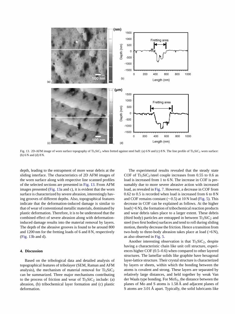
Fig. 13. 2D-AFM image of worn surface topography of Ti3SiC2 when fretted against steel ball: (a) 6 N and (c) 8 N. The line profile of Ti3SiC2 worn surface:(b) 6 N and (d) 8 N.
depth, leading to the entrapment of more wear debris at thesliding interface. The characteristics of 2D AFM images ofthe worn surface along with respective line scanned profilesof the selected sections are presented inFig. 13. From AFMimages presented (Fig. 13a and c), it is evident that the wornsurface is characterized by severe abrasion, interestingly hav-ing grooves of different depths. Also, topographical featuresindicate that the deformation-induced damage is similar tothat of wear of conventional metallic materials, dominated byplastic deformation. Therefore, it is to be understood that thecombined effect of severe abrasion along with deformation-induced damage results into the material removal by layers.The depth of the abrasive grooves is found to be around 800and 1200 nm for the fretting loads of 6 and 8 N, respectively(Fig. 13b and d).
4. Discussion
Based on the tribological data and detailed analysis oftopographical features of tribolayer (SEM, Raman and AFManalysis), the mechanism of material removal for Ti3SiC2can be summarized. Three major mechanisms contributingto the process of friction and wear of Ti3SiC2 include: (a)abrasion, (b) tribochemical layer formation and (c) plasticdeformation.
The experimental results revealed that the steady stateCOF of Ti3SiC2/steel couple increases from 0.55 to 0.6 asload is increased from 1 to 6 N. The increase in COF is pre-sumably due to more severe abrasive action with increasedload, as revealed inFig. 7. However, a decrease in COF from0.62 to 0.5 is recorded when load is increased from 6 to 8 Nand COF remains constant (∼0.5) at 10 N load (Fig. 5). Thisdecrease in COF can be explained as follows. At the higherload (>6 N), the formation of tribochemical reaction productsand wear debris takes place to a larger extent. These debris(third body) particles are entrapped in between Ti3SiC2 andsteel (two first bodies) surfaces and tend to roll during slidingmotion, thereby decrease the friction. Hence a transition fromtwo-body to three-body abrasion takes place at load (>6 N),as also observed inFig. 5.
Another interesting observation is that Ti3SiC2, despitehaving a characteristic chain like unit cell structure, experi-ences higher COF (0.5–0.6) when compared to other layeredstructures. The lamellar solids like graphite have hexagonallayer-lattice structure. Their crystal structure is characterizedby layers or sheets, within which the bonding between theatoms is covalent and strong. These layers are separated byrelatively large distances, and held together by weak Vander Waals type bonding. For MoS2, the distance between theplanes of Mo and S atoms is 1.58A and adjacent planes ofS atoms are 3.01A apart. Typically, the solid lubricants like

aphite, MoS2 are strongly anisotropic in their mechanicaland physical properties. In particular, they are observed to bemuch less resistant to shear deformation in the basal planesthan in other directions. Under the action of a relatively smallforce, displacement of the layers by easy slippage occursleading to low COF under ambient humidity (∼40–50%RH)and temperature (23–25◦C). For example, graphite and MoS2exhibit low COF of∼0.2 at RT and COF increases to 0.8between 400 and 600◦C.23 It is also reported that h-BN hassimilarly low COF of 0.2, which is maintained even at highertemperature of 850◦C. The fact that Ti3SiC2 has higher COFindicates that similar lubrication mechanism does not oper-ate. This is primarily because of the inherent bond structure,as shown inFig. 1. It has been reported in literature24 thatthe interatomic bond length in Ti (1)–Si is around 2.69A,which is lower than the interplanar van der Waals bond lengthin graphite (3.40A). Because of the smaller bond length,the bond strength is expected to be higher in Ti3SiC2 thanother lamellar solids (MoS2, graphite), and this explains thedifficulty of the slippage of Ti C Ti C Ti Si network. Itis believed that this contributes to reasonably higher COF(0.5–0.6) of Ti3SiC2. It should also be mentioned here thatmica, having a characteristic lamellar structure, does notdeform easily under shear force and Ti3SiC2 also exhibitshigher COF than other solid lubricants (WS2, WSe2, CdI2,(CF ) , Graphite, MoS, PTFE).25
abra-s vedf bra-s uet aces.T .A tri-b thetclF ech-a uldb ainsa efor-m t 8 Nl se inw t thed r ofc for-m ationou wearo inso theT lay-e arged a-t be
expected from metallic like bond nature. Also, the interactionbetween Ti planes is mediated by hexagonal layers of C andSi atoms. Previous investigations report that the Ti (1,2)–Cinteraction has a stronger covalent p–d nature when comparedwith the Ti (1)–Si interaction. But, a rigid interaction existsbetween Si–Si atoms inside Si monolayers.5,24 Additionally,polar character of the directional bonding reveal the pres-ence of ionic bonding in TiC and Ti Si interactions. Thisanisotropy of metallic-covalent-ionic bonding was thoughtto be responsible for the Ti3SiC2 plasticity. It is worth tonote here that though the Young’s modulus (E) of the inves-tigated polycrystalline Ti3SiC2 is quite high (316 GPa), theratio of modulus to hardness (∼63) lies in ductile materialsregime.26 According to Barsoum and co-workers4,9 plasticdeformation of Ti3SiC2 was attributed to delamination andkink band formation at above 1200◦C temperature and atroom temperature if grains are oriented. Also, our observationthat the plastic deformation occurs only at higher load of 8 Nindicates that the plasticity of the chain like structure underfretting motion requires a critical contact pressure. The calcu-lated Hertzian contact pressure at 8 N load is around 800 MPaunder investigated fretting conditions. Also, the consider-able fraction of frictional energy is dissipated as heat energy,which is partitioned at the fretting contact between two mat-ing solids. This evidently increases the contact temperature,depending on the sliding speed as well as thermal proper-t thech sur-f ingc
lb nsi-t eda ter-p icalr
5
loadtingF
red
( s a
-curvehigh
ttingda-
x n 2As far as the wear behavior is concerned, severe
ion as well as tribolayer formation is commonly obseror low load regime (1–6 N). The observation of severe aion on Ti3SiC2, even at lowest load 1 N, is primarily do the difference in hardness between mating counterfhe cracking is not observed on worn Ti3SiC2 at 1 N loadt intermediate load of 4 and 6 N, the cracking of theolayer is significant and the non-protective nature of
ribolayer increases the wear rate of Ti3SiC2. The tribo-hemical layer at 6 N load is rich in SiO2 and TiO2 withittle amount of Fe2O3. The formation of TiO2, SiO2 ande2O3 is also recorded at 8 N load. A change in wear mnism is critically observed at high load (8–10 N). It shoe noted here that although the tribochemical wear remn active wear mechanism at load >6 N, the plastic dation appears to be a significant wear mechanism. A
oad, severe plastic deformation contributes to increaear rate. Also, the topographical features indicate thaeformation-induced damage is similar to that of weaonventional metallic materials. The severity of plastic deation is observed to increase at 10 N load. The deformf Ti3SiC2, as explained in existing literature,4,5,9,24can besed to elucidate the observed deformation inducedf Ti3SiC2. In Ti3SiC2, two adjacent covalent bond chaf Ti C Ti C Ti Si form a chain couple with the lengqual to the cell dimension in thec-direction (seeFig. 1).he chains are bonded together with strong metallic Tirs which were found to be inhomogeneous in the free chensity distributions alongc-axis.5 Therefore, the deform
ion behavior of Ti3SiC2 at the worn surfaces can also
ies of two solids in contact. Therefore, it is believed thatombined effect of high contact pressure (at load≥8 N) andigh temperature result in observed plasticity on the worn
aces of Ti3SiC2 under the investigated experimental frettonditions.
In summary, Ti3SiC2 exhibit interesting tribologicaehavior at varying loads under fretting contacts. A tra
ion in friction and fretting wear rate is critically observt 6 N load. The observed transition is a result of the inlay among abrasion (two- versus three-body), tribochemeactions and deformation wear.
. Conclusions
(a) A transition in COF and wear rate is recorded whenincreased from 6 to 8 N. Under the investigated fretconditions, Ti3SiC2/steel tribocouple exhibits high CO(0.5–0.6) and high wear rate (order of 10−5 mm3/N m).At higher load (≥6 N), a decrease in COF is measualong with increase in wear rate.
b) AFM analysis of the worn surface clearly indicateconsiderable increase in roughness parameters (Sa, Sq,Sy,Spk,Sk andSvk) after fretting at 6 N load, when compared to unworn surface. The recorded bearing areaalso correlates well with the increased wear rate atload (6 and 8 N).
(c) Raman spectroscopy analysis reveals that the frewear of investigated tribocouple involves the triboxition of Ti3SiC2 leading to the formation of TiO2 and
hemical wear, i.e. formation and spallingof layer and severe abrasion of Ti3SiC2 are observed asthe dominant wear mechanisms at load≤6 N.
(d) At higher load (8 and 10 N), a transition in wear mecha-nism is noted. Although the tribochemical wear remainsactive, the plastic deformation induced damage signifi-cantly contributes to increased wear rate of Ti3SiC2. Thedeformation at the fretting contact appears to be due toinherent chain structure and metallic bond, characteristicof Ti3SiC2.
Acknowledgment
The authors gratefully acknowledge Dr. S.J. Cho, KRISS,Korea for providing the Ti3SiC2 test samples.
References
1. Jeitschko, W. and Nowotny, H., Die Kristallstructur von Ti3SiC2
– Ein NeuerKomplxcarbid-Typ.Monatsh. Chem., 1967, 98, 329–337.
2. Barsoum, M. W., The MN+1AXN phases: a new class of solids ther-modynamically stable nanolaminates.Solid State Chem., 2000,28(1),201–281.
3. Murugaiah, A., Souchet, A., El-Raghy, T., Radovic, M., Sundberg, M.grain
ides.
es in
ation
H.,.
8. Raghy, T. E., Zavaliangos, A., Barsoum, M. W. and Kalidindi, S.,Damage mechanisms around hardness indentations in Ti3SiC2. J. Am.Ceram. Soc., 1997,80, 513.
9. Raghy, T. E., Barsoum, M. W., Zavaliangos, A. and Kalidindi, S.,Processing and mechanical properties of Ti3SiC2. Part II: Mechanicalproperties.J. Am. Ceram. Soc., 1999,82, 2855–2859.
10. Myhra, S., Summers JWB and Kisi, E. H., Ti3SiC2 – a layeredceramic exhibiting ultra-low friction.Mater. Lett., 1999,39, 6–11.
11. Raghy, T. E., Blau, P. and Barsoum, M. W., Effect of grain size onfriction and wear behavior of Ti3SiC2. Wear, 2000,238, 125–130.
12. Zhang Yi, Ding, G. P., Zhou, Y. C. and Cai, B. C., Ti3SiC2 – aself-lubricating ceramic.Mater. Lett., 2002,55, 285–289.
13. Tang, H. B., Fang, Y. L. and Wang, H. M., Microstructure and drysliding wear resistance of a Cr13Ni5Si2 ternary metal silicide alloy.Acta Mater., 2004,52(7), 1773.
14. Waterhouse, R. B., Fretting wear.ASM Handbook, Vol. 18. ASMInternational, 1992, p. 242.
15. Brown, S. R., ASTM special Technical Publication 780. Warminster,PA, 1982, p. 1.
16. Sarkar, D., Ahn, S., Kang, S. and Basu, B., Fretting wear of TiCN–Nicermet – influence of secondary carbide content.P/M Sci. Technol.Briefs, 2003,5(3), 5–11.
17. Serincan, U., Kartopu, G., Guennes, A., Finstad, T. G., Turan, R.,Ekinci, Y. et al., Characterization of Ge nanocrystals embedded inSiO2 by Raman spectroscopy.Semicond. Sci. Technol., 2004, 19,247–251.
18. Tjong, S. C.,Mater. Character., 1991,26, 29.19. Chen, M., Kato, K. and Adachi, K., Friction and wear of selfmated
SiC and Si3N4 sliding in water.Wear, 2001,250, 246–255.20. Jeng, M. C. and Yan, L. Y., Environmental effects on wear behavior
of Al O . Wear, 1993,161, 11–16.2
2
2
2 M.
2
2 om-
and Barsoum, M. W., Tape casting, pressureless sintering, andgrowth in Ti3SiC2 compacts.J. Am. Ceram. Soc., 2004,87(4), 550.
4. Barsoum, M. W. and Raghy, T. E., Room temperature ductile carbMet. Mat. Trans., 1999,30A, 363–369.
5. Zhou, Y. and Sun, Z., Electronic structure and bonding propertilayered ternary carbide Ti3SiC2. J. Phys.: Condens. Matter., 2000,12(28), L457–L462.
6. Barsoum, M. W. and Raghy, T. E., Synthesis and characterizof a remarkable ceramic: Ti3SiC2. J. Am. Ceram. Soc., 1996,79(7),1953–1956.
7. Barsoum, M. W., Raghy, T. E., Rawn, C., Porter, W., Wang,Payzant, A.et al., Thermal properties of Ti3SiC2. J. Phys. ChemSolids, 1999,60, 429–439.
2 3
1. Hsu, S. M. and Shen, M. C., Ceram. Wear Maps.Wear, 1996,200,154–175.
2. Barsoum, M. W., Raghy, T. E. and Ogbuji, L., Oxidation of Ti3SiC2
in air. J. Electrochem. Soc., 1997,144, 2508–2516.3. Deacon, R., Lubrication by lamellar solids.Proc. Roy. Soc., 1957,
243A, 464.4. Medvedeva, N. I., Novikov, D. L., Ivanovsky, A. L., Kuznetsov,
V. and Freeman, A. J., Electronic properties of Ti3SiC2-based solidsolutions.Phys. Rev. B, 1998,58, 16042–16050.
5. Bhushan, B.,Principles and Applications of Tribology. John Wiley& Sons, 1999, p. 413.
6. Pampuch, R., Lis, J., Stobierski, L. and Tymkiewicz, M., Solid cbustion synthesis of Ti3SiC2. J. Eur. Ceram. Soc., 1989,5, 283.


![JJC Jordan Journal of Chemistry Vol. 3 No.3, 2008, pp. 281 ......friction an wear [21]. Fretting Wear The fretting wear results of the 480-nm thick Ag 49 Ni 51 and the 510-nm thick](https://static.fdocuments.us/doc/165x107/60cd188c19d835726f16989c/jjc-jordan-journal-of-chemistry-vol-3-no3-2008-pp-281-friction-an-wear.jpg)