Understanding RF Fundamentals and thed2zmdbbm9feqrf.cloudfront.net/2013/usa/pdf/BRKEWN-2017.pdf ·...
149
Transcript of Understanding RF Fundamentals and thed2zmdbbm9feqrf.cloudfront.net/2013/usa/pdf/BRKEWN-2017.pdf ·...


Understanding RF Fundamentals and the Radio Design of Wireless Networks Session BRKEWN-2017
Fred Niehaus N8CPI – Technical Marketing Engineer
Wireless Networking Group –
Email [email protected]

© 2013 Cisco and/or its affiliates. All rights reserved. BRKEWN-2017 Cisco Public
Session Abstract
This session focuses on understanding the often overlooked Radio Frequency part of designing and deploying a Wireless LAN Network.
It discusses 802.11 radio, MIMO, APs and antennas placements, antenna patterns...
It covers the main environments such as carpeted offices, campuses and conference centers, and it provides feedback based on lessons learned from challenging deployments such as outdoor/stadium/rail deployments and manufacturing areas.
3

© 2013 Cisco and/or its affiliates. All rights reserved. BRKEWN-2017 Cisco Public
Session Agenda – Objectives
• What is radio and how did we get here? • Basic 802.11 Radio Hardware & Terminology • Antenna Basics – Single, Dual Band and MIMO Antennas • Interpreting antenna patterns – Cisco/Aironet Richfield Ohio Facilities • Understanding fundamentals of, Beamforming and Cisco ClientLink • Basic understanding of 802.11n and 802.11ac fundamentals including
MIMO, Channel bonding, Multi-path, Spatial Streams and Multiplexing…
• Installation challenges, when to use different APs – avoiding potential problems
4

© 2013 Cisco and/or its affiliates. All rights reserved. BRKEWN-2017 Cisco Public
What We Won’t Be Covering • Wireless Security (dedicated sessions for that) • Clean Air (separate sessions for that) • wIDS/wIPS (Wireless Intrusion Prevention Systems) • High density deployments (separate session for that) • LBS (Location Based Services) or Context Aware • Walled garden, captive portals • SP Wi-Fi, 3G offload and HotSpot 2.0 • WLAN management • 802.11n going beyond RF characteristics
5

What is Radio? How did we end up on these Frequencies?
© 2013 Cisco and/or its affiliates. All rights reserved. BRKEWN-2017 Cisco Public
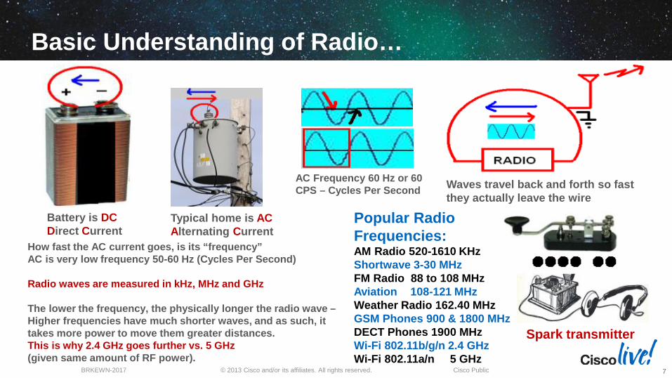
Basic Understanding of Radio…
Battery is DC Direct Current
Typical home is AC Alternating Current
AC Frequency 60 Hz or 60 CPS – Cycles Per Second Waves travel back and forth so fast
they actually leave the wire
Popular Radio Frequencies: AM Radio 520-1610 KHz Shortwave 3-30 MHz FM Radio 88 to 108 MHz Aviation 108-121 MHz Weather Radio 162.40 MHz GSM Phones 900 & 1800 MHz DECT Phones 1900 MHz Wi-Fi 802.11b/g/n 2.4 GHz Wi-Fi 802.11a/n 5 GHz
How fast the AC current goes, is its “frequency” AC is very low frequency 50-60 Hz (Cycles Per Second) Radio waves are measured in kHz, MHz and GHz The lower the frequency, the physically longer the radio wave – Higher frequencies have much shorter waves, and as such, it takes more power to move them greater distances. This is why 2.4 GHz goes further vs. 5 GHz (given same amount of RF power).
7
Spark transmitter

© 2013 Cisco and/or its affiliates. All rights reserved. BRKEWN-2017 Cisco Public
The Radio Spectrum in the US
Source US Department of Commerce http://www.ntia.doc.gov/osmhome/allochrt.pdf
8
© 2013 Cisco and/or its affiliates. All rights reserved. BRKEWN-2017 Cisco Public
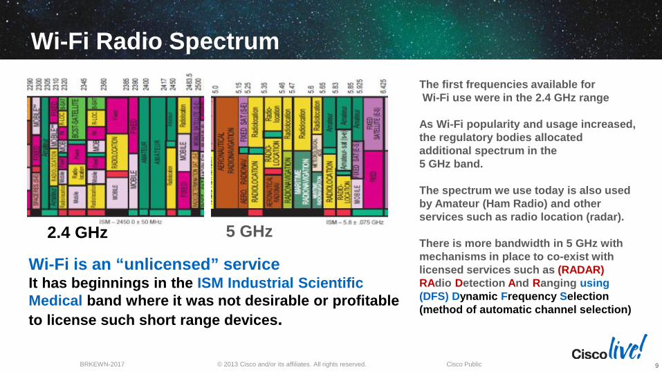
Wi-Fi Radio Spectrum
Wi-Fi is an “unlicensed” service It has beginnings in the ISM Industrial Scientific Medical band where it was not desirable or profitable to license such short range devices.
The first frequencies available for Wi-Fi use were in the 2.4 GHz range As Wi-Fi popularity and usage increased, the regulatory bodies allocated additional spectrum in the 5 GHz band. The spectrum we use today is also used by Amateur (Ham Radio) and other services such as radio location (radar). There is more bandwidth in 5 GHz with mechanisms in place to co-exist with licensed services such as (RADAR) RAdio Detection And Ranging using (DFS) Dynamic Frequency Selection (method of automatic channel selection)
2.4 GHz 5 GHz
9

© 2013 Cisco and/or its affiliates. All rights reserved. BRKEWN-2017 Cisco Public
Wi-Fi Radio Spectrum 2.4 GHz
Even today, many portable devices in use are limited to 2.4 GHz only, including newer devices, but this is changing as newer 802.11ac (5-GHz) devices emerge 802.11b/g is 2.4 GHz 802.11a is 5 GHz 802.11n (can be either band) 2.4 or 5 GHz
The 2.4 GHz spectrum in the US has 3 non-overlapping channels 1, 6 and 11. There are plenty of channels in the 5 GHz spectrum and they do not overlap 2.4 GHz and 5 GHz are different portions of the radio band and usually require separate antennas Most, if not all, 5 GHz devices also have support for 2.4 GHz - however there are still many 2.4 GHz only devices.
10

© 2013 Cisco and/or its affiliates. All rights reserved. BRKEWN-2017 Cisco Public
Wi-Fi Radio Spectrum 2.4 GHz
11

© 2013 Cisco and/or its affiliates. All rights reserved. BRKEWN-2017 Cisco Public
Wi-Fi Radio Spectrum 5 GHz Channels
Note: 5 GHz channels do not have the severe overlap that 2.4 GHz channels have but they use DFS to enable sharing of the band
12

© 2013 Cisco and/or its affiliates. All rights reserved. BRKEWN-2017 Cisco Public
Dynamic Frequency Selection (DFS) 5 GHz When Radar Signal is Present
Access Points detect radar activity and change channels so as not to cause interference with licensed services who have priority This can result in lower available channels and loss of some UNI-2 and UNI-2 extended bands. UNI-1 and UNI-3 bands are outside of the weather radar and do not change. Radar signals may be present near airports, military bases or large cities
UNI 1 UN 3
13

© 2013 Cisco and/or its affiliates. All rights reserved. BRKEWN-2017 Cisco Public
A Radio Needs a Proper Antenna
Antennas are identified by color Blue indicates 5 GHz Black indicates 2.4 GHz Orange indicates Both
As the frequency goes up, the radiating element gets smaller
Antennas are custom made for the frequency to be used. Some antennas have two radiating elements to allow for both frequency bands (2.4 and 5 GHz) in one antenna enclosure.
Omni-Directional antennas like the one on the left, radiate much like a raw light bulb would everywhere in all directions
Directional antennas like this “Patch” antenna radiate forward like placing tin foil behind the light bulb or tilting and directing the lamp shade Note: Same RF energy is used but results in greater range as it is focused towards one direction, at the cost of other coverage areas
14

© 2013 Cisco and/or its affiliates. All rights reserved. BRKEWN-2017 Cisco Public
Complex Modulation Schemes
Radio technology has a lot in common with that old twisted pair phone line that started out at 300 baud and then quickly increased In order to get faster data rates, (throughput) into the radio signal, complex modulation schemes as QPSK or 64 bit QAM is used. Generally speaking, the faster the data rate the more powerful the signal needs to be at the receiver end to be properly decoded. Take-away here is: 802.11n is a method of using special modulation techniques and is *not* specific to a frequency like 2.4 or 5 GHz 802.11n can be used in either band
High-density modulation schemes such as 64-QAM “Quadrature Amplitude Modulation” is used by 802.11n to get additional throughput higher than what is found in 802.11a/b/g. This is one of the advantages of 802.11n Note: Newer 802.11ac modes can use up to 256-QAM
Example of 802.11n Modulation Coding Schemes
15

Basic 802.11 RF Terminology Hardware identification

© 2013 Cisco and/or its affiliates. All rights reserved. BRKEWN-2017 Cisco Public
Common RF Terms Attenuation – a loss in force or intensity – As radio waves travel in media such as coaxial cable attenuation occurs.
BER – Bit Error Rate - the fraction of bits transmitted that are received incorrectly.
Channel Bonding – act of combining more than one channel for additional bandwidth
dBd – abbreviation for the gain of an antenna system relative to a dipole
dBi – abbreviation for the gain of an antenna system relative to an isotropic antenna
dBm – decibels milliwatt -- abbreviation for the power ratio in decibels (dB) of the measured power referenced to one milliwatt of transmitted RF power.
Multipath – refers to a reflected signal that combines with a true signal resulting in a weaker or some cases a stronger signal.
mW – milliwatt a unit of power equal to one thousandth of a watt (usually converted to dBm)
Noise Floor – The measure of the signal created from the sum of all the noise sources and unwanted signals appearing at the receiver. This can be adjacent signals, weak signals in the background that don’t go away, electrical noise from electromechanical devices etc.
Receiver Sensitivity – The minimum received power needed to successfully decode a radio signal with an acceptable BER. This is usually expressed in a negative number depending on the data rate. For example the AP-1140 Access Point requires an RF strength of at least negative -91 dBm at 1 MB and an even higher strength higher RF power -79 dBm to decode 54 MB
Receiver Noise Figure – The internal noise present in the receiver with no antenna present (thermal noise).
SNR – Signal to Noise Ratio – The ratio of the transmitted power from the AP to the ambient (noise floor) energy present.
For Your Reference
17

© 2013 Cisco and/or its affiliates. All rights reserved. BRKEWN-2017 Cisco Public
Identifying RF Connectors
RP-TNC Connector Used on most Cisco Access Points
“N” Connector Used on the 15xx Mesh and outdoor APs
“SMA” Connector “Pig tail” type cable assemblies
“RP-SMA” Connector Used on some Linksys Products
18
For Your Reference

© 2013 Cisco and/or its affiliates. All rights reserved. BRKEWN-2017 Cisco Public
Antenna Cables – LMR Series This is a chart depicting different types of Microwave LMR Series coaxial cable. Cisco uses Times Microwave cable and has standardized on two types: Cisco Low Loss (LMR-400) Ultra Low Loss (LMR-600). LMR-600 is recommended when longer cable distances are required Larger cables can be used but connectors are difficult to find and larger cable is harder to install
Trivia: LMR Stands for “Land Mobile Radio” 19
For Your Reference

© 2013 Cisco and/or its affiliates. All rights reserved. BRKEWN-2017 Cisco Public
Some Antenna Cables Characteristics
Foil shield and braid LMR-400 3/8 inch LMR-600 ½ inch
LMR type cable has a Cisco P/N like this… AIR-CAB-050-LL-R AIR - Aironet CAB – Cable 050 - Length LL - Low Loss (LMR-400) R - RP-TNC connector
20
For Your Reference

Antenna Basics

© 2013 Cisco and/or its affiliates. All rights reserved. BRKEWN-2017 Cisco Public
Antenna Basics Antenna - a device which radiates and/or receives radio signals Antennas are usually designed to operate at a specific frequency Some antennas have more than one radiating element (example Dual Band) Antenna Gain is characterized using dBd or dBi
– Antenna gain can be measured in decibels against a reference antenna called a dipole and the unit of measure is dBd (d for dipole)
– Antenna gain can be measured in decibels against a computer modeled antenna called an “isotropic” dipole <ideal antenna> and the unit of measure is
dBi the “i” is for isotropic dipole which is a computer modeled “perfect” antenna WiFi antennas are typically rated in dBi.
– dBi is a HIGHER value (marketing folks like higher numbers) – Conventional radio (Public safety) tend to use a dBd rating. – To convert dBd to dBi simply add 2.14 so a 3 dBd = 5.14 dBi
22

© 2013 Cisco and/or its affiliates. All rights reserved. BRKEWN-2017 Cisco Public
How Does a Omni-Directional Dipole Radiate? The radio signal leaves the center wire using the ground wire
(shield) as a counterpoise to radiate in a 360 degree pattern
Low gain Omni radiates much like a light bulb “360” degrees
23

© 2013 Cisco and/or its affiliates. All rights reserved. BRKEWN-2017 Cisco Public
Dipole
A dipole does not require a ground plane as the bottom half is the ground (counterpoise).
Monopole
A Monopole requires a ground plane – (conductive surface)
808 Ft Broadcast Monopole WSM 650 AM (erected in 1932)
Antenna Theory (Dipole & Monopole)
24

© 2013 Cisco and/or its affiliates. All rights reserved. BRKEWN-2017 Cisco Public
Monopoles were added to our antenna line primarily for aesthetics Monopoles are smaller and require a metal surface to properly radiate
Antenna Theory (Dipole & Monopole)
25

© 2013 Cisco and/or its affiliates. All rights reserved. BRKEWN-2017 Cisco Public
How Does a Directional Antenna Radiate? Although you don’t get additional RF power with a directional antenna, it does
concentrate the available energy into a given direction resulting in greater range.
Also a receive benefit - by listening in a given direction, this can limit the reception of unwanted signals (interference) from other directions for better performance
A dipole called the “driven element” is placed in front of other elements. This motivates the signal to go forward in a given direction for gain. (Inside view of the Cisco AIR-ANT1949 - 13.5 dBi Yagi)
26

© 2013 Cisco and/or its affiliates. All rights reserved. BRKEWN-2017 Cisco Public
Patch Antenna: a Look Inside
The 9.5 dBi Patch called AIR-ANT5195-R
Patch antennas can have multiple radiating elements that combine for gain. Sometimes, a metal plate is used behind the antenna as a reflector for more gain.
Cisco Public 27
Patch and Yagi antennas favor the direction the antenna is pointed – like a flashlight

© 2013 Cisco and/or its affiliates. All rights reserved. BRKEWN-2017 Cisco Public
Antennas Identified by Color
Cisco Antenna Color Coding Black indicates 2.4 GHz Blue indicates 5 GHz Orange indicates 2.4 & 5 GHz (used on AP-1600, 2600 @ 3600)
Cisco antennas & cables are color coded – Black or no markings indicate 2.4 GHz
28
For Your Reference

© 2013 Cisco and/or its affiliates. All rights reserved. BRKEWN-2017 Cisco Public
Most Common discrete 2.4 GHz Antennas
© 2011 Cisco and/or its affiliates. All rights reserved. Cisco Public
Single element antennas have one cable Diversity antennas have two cables MIMO (802.11n) can have three or more cables
29
For Your Reference

© 2013 Cisco and/or its affiliates. All rights reserved. BRKEWN-2017 Cisco Public
Most Common discrete 5 GHz Antennas
Single element antennas have one cable Diversity antennas have two cables MIMO (802.11n) can have three or more cables
30
For Your Reference

© 2013 Cisco and/or its affiliates. All rights reserved. BRKEWN-2017 Cisco Public
Guide to Antenna Part Numbers
31
For Your Reference

© 2013 Cisco and/or its affiliates. All rights reserved. BRKEWN-2017 Cisco Public 32
For Your Reference Most Common 802.11n Antennas
Indoor Access Points (1262 and 3502e) <First Generation AP’s>
These are Single Radiating Element antennas designed for Access Points that have single band 2.4 or 5 GHz connectors (black or blue color)
Note: do *NOT* use on units with ORANGE label (1600, 2600 & 3600)
© 2013 Cisco and/or its affiliates. All rights reserved. BRKEWN-2017 Cisco Public 33
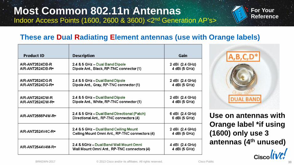
For Your Reference Most Common 802.11n Antennas
Indoor Access Points (1600, 2600 & 3600) <2nd Generation AP’s>
Use on antennas with Orange label *if using (1600) only use 3 antennas (4th unused)
These are Dual Radiating Element antennas (use with Orange labels)

Understanding and Interpreting Antenna Patterns

© 2013 Cisco and/or its affiliates. All rights reserved. BRKEWN-2017 Cisco Public
Low gain dipoles radiate everywhere think “light bulb”
Understanding Antenna Patterns Dipole (Omni-Directional)
35

© 2013 Cisco and/or its affiliates. All rights reserved. BRKEWN-2017 Cisco Public
When three monopoles are next to each other – the radiating elements interact slightly with each other – The higher gain 4 dBi also changes elevation more compared to the lower gain 2.2 dBi Dipole
Understanding Antenna Patterns Monopole (Omni-Directional) MIMO
36

© 2013 Cisco and/or its affiliates. All rights reserved. BRKEWN-2017 Cisco Public
A low gain Patch Antenna
Understanding Antenna Patterns Patch (Directional)
37

© 2013 Cisco and/or its affiliates. All rights reserved. BRKEWN-2017 Cisco Public
A High Gain Four element Patch Array
Understanding Antenna Patterns Patch (Higher Gain Directional)
38

© 2013 Cisco and/or its affiliates. All rights reserved. BRKEWN-2017 Cisco Public
Four element Patch Array
Understanding Antenna Patterns Patch (Higher Gain Directional)
39

© 2013 Cisco and/or its affiliates. All rights reserved. BRKEWN-2017 Cisco Public
Elevation plane has nulls due to high gain 14 dBi
AIR-ANT2414S-R 14 dBi Sector 2.4 GHz
Understanding Antenna Patterns Sector (Higher Gain Directional)
40

© 2013 Cisco and/or its affiliates. All rights reserved. BRKEWN-2017 Cisco Public
AIR-ANT2414S-R 14 dBi Sector 2.4 GHz
Elevation plane has nulls due to high gain 14 dBi but this antenna was designed with “Null-Fill” meaning we scaled back the overall antenna gain so as to have less nulls or low signal spots on the ground.
Understanding Antenna Patterns Sector (Higher Gain Directional)
41

© 2013 Cisco and/or its affiliates. All rights reserved. BRKEWN-2017 Cisco Public
The Richfield Ohio (Aironet) Facility A Quick Peek Where Antennas Are Designed...
42

© 2013 Cisco and/or its affiliates. All rights reserved. BRKEWN-2017 Cisco Public
The Richfield Ohio (Aironet) Facility Qualifying Cisco and 3rd Party Antennas
Satimo software compatible with Stargate-64 System. Basic measurement tool is 8753ES Network Analyzer.
Cisco Anechoic chamber using an 45 cm absorber all the way, around 1-6 GHz Anechoic means “without echo”
43

© 2013 Cisco and/or its affiliates. All rights reserved. BRKEWN-2017 Cisco Public
The Richfield Ohio (Aironet) Facility Regulatory Compliance Testing is Performed in this Chamber
Cisco Public 44

© 2013 Cisco and/or its affiliates. All rights reserved. BRKEWN-2017 Cisco Public
Yes We Have Just a Few Access Points Running…
45

© 2013 Cisco and/or its affiliates. All rights reserved. BRKEWN-2017 Cisco Public
RF Screen Rooms Everywhere Copper Shielding (Faraday Cage)
46

© 2013 Cisco and/or its affiliates. All rights reserved. BRKEWN-2017 Cisco Public
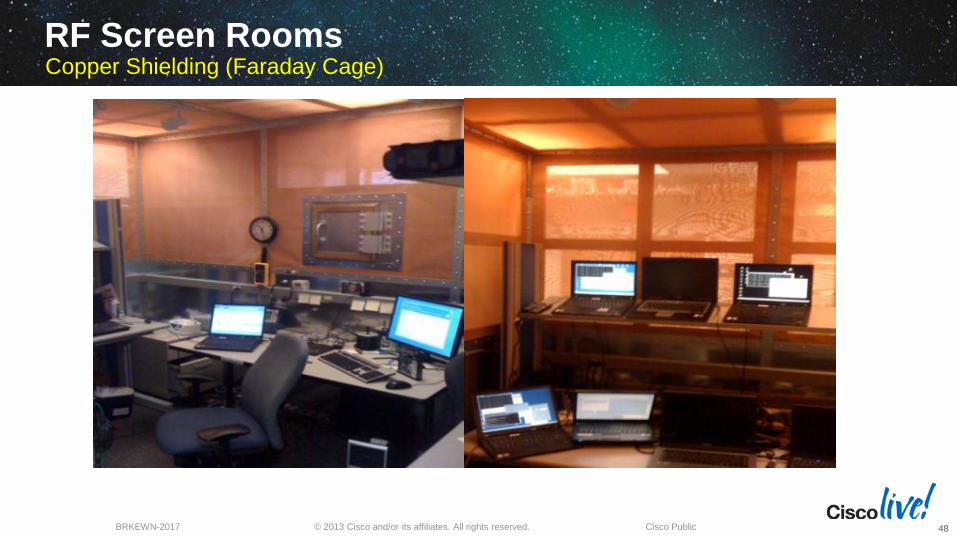
Cables are typically fiber and exit through well shielded holes
Doors have copper fingers and latch tight forming an RF seal
RF Screen Rooms Copper Shielding on Top Metal on Bottom
47
© 2013 Cisco and/or its affiliates. All rights reserved. BRKEWN-2017 Cisco Public
RF Screen Rooms Copper Shielding (Faraday Cage)
48

© 2013 Cisco and/or its affiliates. All rights reserved. BRKEWN-2017 Cisco Public
Cisco Richfield Facility
49

Understanding Multipath Diversity and Beamforming

© 2013 Cisco and/or its affiliates. All rights reserved. BRKEWN-2017 Cisco Public
As radio signals bounce off metal objects they often combine at the receiver This often results in either an improvement “constructive” or a “destructive” type of interference
Note: Bluetooth type radios that “hop” across the entire band can reduce multipath interference by constantly changing the angles of multipath as the radio wave increases and decreases in size (as the frequency constantly changes). The downside is that throughput using these “hopping” methods are very limited but multipath is less of a problem
Understanding Multipath Multipath can change Signal Strength
51

© 2013 Cisco and/or its affiliates. All rights reserved. BRKEWN-2017 Cisco Public
As the radio waves bounce, they can arrive at slightly different times and angles causing signal distortion and potential signal strength fading Different modulation schemes fair better – 802.11a/g uses a type of modulation based on symbols and is an improvement over the older modulation types used with 802.11b clients
802.11n with more receivers can use destructive interference (multipath) as a benefit but it is best to reduce multipath conditions
Understanding Multipath Multipath Reflections Can Cause Distortion
52

© 2013 Cisco and/or its affiliates. All rights reserved. BRKEWN-2017 Cisco Public
Understanding Diversity (SISO) 802.11a/b/g had just one radio per band diversity was limited
Non-802.11n diversity Access Points use two antennas sampling each antenna choosing the one with the least multi-path distortion
Cisco 802.11a/b/g Access Points start off favoring the right (primary antenna port) then if multi-path or packet retries occur it will sample the left port and switch to that antenna port if the signal is better. Note: Diversity Antennas should always cover the same cell area
53

© 2013 Cisco and/or its affiliates. All rights reserved. BRKEWN-2017 Cisco Public
Understanding Diversity (MIMO) MRC Maximal Ratio Combining (Three Radios)
Receiver benefit as each antenna has a radio section MRC is done at Baseband using DSP techniques Multiple antennas and multiple RF sections are used in parallel The multiple copies of the received signal are corrected and combined at Baseband for
maximum SNR (Signal to Noise) benefit This is a significant benefit over traditional 802.11a/b/g diversity where only one radio is used
54

© 2013 Cisco and/or its affiliates. All rights reserved. BRKEWN-2017 Cisco Public
3 Antennas Rx Signals
Combined Effect (Adding all Rx Paths)
MRC Effect on Received Signal Maximal Ratio Combining
55

© 2013 Cisco and/or its affiliates. All rights reserved. BRKEWN-2017 Cisco Public
Beam-forming allows the signal to be best directed towards the client. This results in a strong signal to the client reducing need for retries Note antennas were moved in the picture for illustration purposes – Never place antennas like this
Understanding Client Link 1.0 & 2.0 Why You Want to direct (Beam-form) the signal to the client)
56

© 2013 Cisco and/or its affiliates. All rights reserved. BRKEWN-2017 Cisco Public
Client Link doesn’t only help at the edge of the network, but by pushing the signal directly at the client - it permits easier decoding maintaining higher data rate connectivity (rate over range) on the downlink side
Simple Example of Beamforming
57

© 2013 Cisco and/or its affiliates. All rights reserved. BRKEWN-2017 Cisco Public
Beamforming: ClientLink 1.0 (Introduced in AP-1140)
The AP-1140/1260/3500 has dual band radio support using single band antennas. Each radio band (2.4 & 5 GHz) has separate independent radios Two transceivers (Tx/Rx) per band This two transceiver design allows for beam-forming to legacy clients 802.11a/g - this is called Client Link.
AP1140, 1260 and 3500 can beamform to legacy 802.11a/g clients. This is called Client Link 1.0 and supports up to 15 clients per radio Note: Client Link 1 & 2 works on the DOWNLINK (AP to CLIENT) so the client can better decode packets
58

© 2013 Cisco and/or its affiliates. All rights reserved. BRKEWN-2017 Cisco Public
2nd Generation Series AP’s with ClientLink 2.0 Client Link 2.0 is Client Link with Enhanced .11n Beam-forming
2600 & 3600 Series APs have four transceivers per band and all the antennas are used in the Client Link 2.0 beam-forming process More radios, less antennas, all 8 radios (4 per band) are Transmit/Receive “Tx/Rx”
59
Cisco 2600 & 3600 Access Points fully support Cisco Client Link 2.0 (beam-forming) to 802.11a/g/n clients as well as 802.11n clients @ 1, 2 & 3 Spatial Streams Take away – CLIENT LINK 2.0 beam-forms to all clients today improving the overall user experience and performance
© 2013 Cisco and/or its affiliates. All rights reserved. BRKEWN-2017 Cisco Public
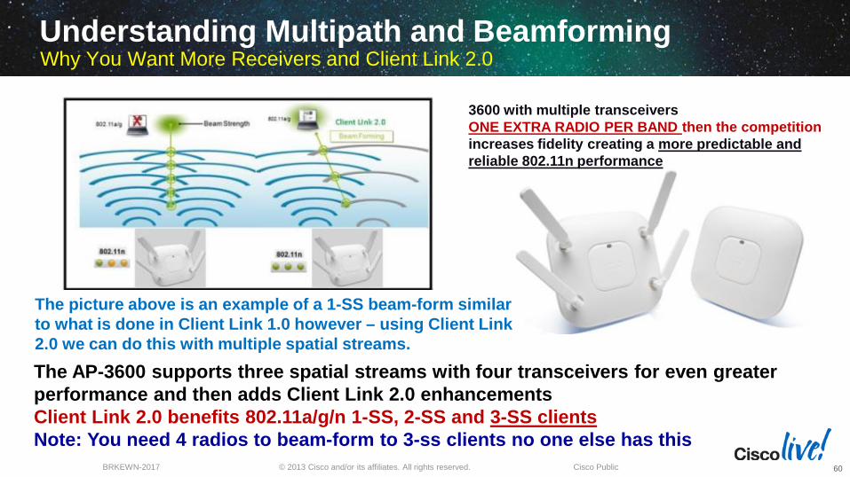
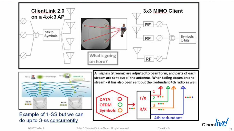
The picture above is an example of a 1-SS beam-form similar to what is done in Client Link 1.0 however – using Client Link 2.0 we can do this with multiple spatial streams.
3600 with multiple transceivers ONE EXTRA RADIO PER BAND then the competition increases fidelity creating a more predictable and reliable 802.11n performance
The AP-3600 supports three spatial streams with four transceivers for even greater performance and then adds Client Link 2.0 enhancements Client Link 2.0 benefits 802.11a/g/n 1-SS, 2-SS and 3-SS clients Note: You need 4 radios to beam-form to 3-ss clients no one else has this
Understanding Multipath and Beamforming Why You Want More Receivers and Client Link 2.0
60
© 2013 Cisco and/or its affiliates. All rights reserved. BRKEWN-2017 Cisco Public 61

Understanding 802.11n

© 2013 Cisco and/or its affiliates. All rights reserved. BRKEWN-2017 Cisco Public
Review of 802.11a and 802.11b/g
1 Transmitter & 1 Receiver (per band) – up to 54 Mbps
Early diversity Access Points use two antennas with one radio per band sampling each antenna - choosing the one with the least multi-path distortion and then transmitting back on the same antenna
Since speeds were only 54 Mbps 10/100 ports were fine
Since PoE was 15.4W the radios had plenty of power the higher gain antennas above 6 dBi were permitted
Both Indoor/Outdoor was permitted without frequency restrictions 802.11n introduced restrictions for outdoors creating the 3502P
63

© 2013 Cisco and/or its affiliates. All rights reserved. BRKEWN-2017 Cisco Public
Review – 802.11n “G1” first generation APs
Up to 3 radios per band – speeds up to 300 Mbps
2.4 GHz (802.11b/g/n) and 5 GHz (802.11a/n) – Support for 2-spatial streams
Lots of antennas (typically 6) three for each band
Antennas are single band single radiating elements identified by black and blue (5-GHz) colors
Introduction of ClientLink (beam-forming)
Modularity is a GOOD THING
Remember me? I’m a 1250 Built like a tank October 2007
64

© 2013 Cisco and/or its affiliates. All rights reserved. BRKEWN-2017 Cisco Public
Review – 802.11n “G2” second generation AP-3600 Up to 4 radios per band – speeds up to 450 Mbps
Support for 3 Spatial Streams 2.4 GHz (802.11b/g/n) and 5 GHz (802.11a/n)
Antennas are dual band - dual radiating elements identified by an orange stripe resulting in the need for less physical antennas
Introduction of ClientLink 2.0 better Beam-forming
Introduction of upgrade option modules
Security Module & 802.11ac Module
Note: New .11ac module brings increased performance to the AP-3600 Access Point up to 1.3 Gbps
65

© 2013 Cisco and/or its affiliates. All rights reserved. BRKEWN-2017 Cisco Public
802.11n MIMO terminology Understanding .11n components (Multiple Input Multiple Output)
“abcdef” “def”
“abc” MIMO AP
Sending side: send more symbols, in parallel (spatial multiplexing)
“abc” “abc”
“abc”
MIMO AP
Receiving side: synchronize signals for better signal (Maximal Ratio Combining, MRC)
Spatial Multiplexing – A method for boosting wireless bandwidth by taking advantage of multiplexing which is the ability within the radio to send out information over two or more transmitters concurrently (in parallel) known as “spatial streams”.
MRC – Maximal Ratio Combining a method that combines signals from multiple antennas taking into account factors such as signal to noise ratio to decode the signal with the best possible Bit Error Rate.
66

© 2013 Cisco and/or its affiliates. All rights reserved. BRKEWN-2017 Cisco Public
802.11n MIMO terminology Understanding .11n components (Multiple Input Multiple Output)
TxBF – Transmit Beam-Forming – Signals are sent on separate antennas that are coordinated to combine constructively at the receive antenna (.11n Enhanced Beam Forming) and Cisco ClientLink
EBF didn’t happen in .11n so Cisco addressed with ClientLink
67

© 2013 Cisco and/or its affiliates. All rights reserved. BRKEWN-2017 Cisco Public
802.11n MIMO terminology Understanding .11n/ac components (Multiple Input Multiple Output)
Channel Bonding – Use of more than one frequency or channel for more bandwidth. (Like going from a 2 lane highway to a 4 lane)
40 MHz = two aggregated 20 MHz channels plus gained space – (+2x speed)
Packet aggregation – Permits more efficient use of the RF spectrum Reducing ACK times for more faster throughput
68

© 2013 Cisco and/or its affiliates. All rights reserved. BRKEWN-2017 Cisco Public
Channel Bonding – Subcarriers
When using the 40-MHz bonded channel, 802.11n takes advantage of the fact that each 20-MHz channel has a small amount of the channel that is reserved at the top and bottom, to reduce interference in those adjacent channels. When using 40-MHz channels, the top of the lower channel and the bottom of the upper channel don't have to be reserved to avoid interference. These small parts of the channel can now be used to carry information. By using the two 20-MHz channels more efficiently in this way, 802.11n achieves slightly more than doubling the data rate when moving from 20-MHz to 40-MHz channels
802.11n can use both 20-MHz and 40-MHz channels. The 40-MHz channels in 802.11n are two adjacent 20-MHz channels, bonded together.
69

© 2013 Cisco and/or its affiliates. All rights reserved. BRKEWN-2017 Cisco Public
2.4 GHz Channel Bandwidths 40 MHz Not Permitted or Supported (Enterprise WLAN)
Cisco Public 70

© 2013 Cisco and/or its affiliates. All rights reserved. BRKEWN-2017 Cisco Public
Example: ETSI Lower Band 5-GHz Channel Bonding
In 40-MHz you define the control channel this is the channel that is used for communication by Legacy .11a clients. The Extension channel is the bonded channel that “HT” High Throughput “802.11n clients use in addition to the control channel for higher throughput as they send data on BOTH channels
71

© 2013 Cisco and/or its affiliates. All rights reserved. BRKEWN-2017 Cisco Public
Suggested Guidelines on Channel Bonding
20 MHz mode is suggested if… – you have lots of voice clients. – you have lots of non-11n capable 5 GHz clients – you will be deploying a transition of mixed 11a & 11n infrastructure: 40 MHz (Bonded channel) mode is suggested if… – You have few voice clients (less than 10 per AP) – You expect to have predominantly 11n clients that support 40 MHz operation. – You are doing bandwidth-intensive file transfers such as video downloads, wireless backups, etc.
72

© 2013 Cisco and/or its affiliates. All rights reserved. BRKEWN-2017 Cisco Public
Understanding Guard Interval
Guard Interval (GI) – Period of time between each a OFDM symbol that is used to minimize inter-symbol interference. This type of interference is caused in multipath environments when the beginning of a new symbol arrives at the receiver before the end of the last symbol is done.
Default GI mode for 802.11n is 800 nanoseconds If you set a shorter interval it will go back to the long guard interval in the event retries happen to occur
Cisco Public 73

© 2013 Cisco and/or its affiliates. All rights reserved. BRKEWN-2017 Cisco Public
802.11n Data Rates
AP-1040,1140, 1250,1260,3500 New AP-700 & 1600 can support Up to 2-Streams 300 Mbps (MCS15)
AP-2600, AP3600 can support Up to 3-Streams 450 Mbps (MCS23) w/o .11ac module
74

© 2013 Cisco and/or its affiliates. All rights reserved. BRKEWN-2017 Cisco Public
So to Recap: 802.11n Operation Throughput Improves When All Things Come Together
Cisco Public 75

© 2013 Cisco and/or its affiliates. All rights reserved. BRKEWN-2017 Cisco Public
802.11n “Things that never really got much traction” Greenfield header (pure 802.11n, for networks with no 802.11a/b/g stations)
by the way this is a bad idea as you want to be a good RF neighbor. FYI - Greenfield will not be supported in 802.11ac. 4 Spatial streams for up to 600 Mbps (assuming bonded 40 MHz and short
400ns GI) just too many issues (lack of clients, PoE considerations etc.) FYI .11ac 3-SS Wave-1 Channel bonding in 2.4 GHz for enterprise (just not enough channels) as
you can only do so much on 2.4 GHz as there isn’t that much spectrum. FYI- 802.11ac is 5 GHz only Explicit beam-forming (clients really didn’t support this) FYI- Supported with
.11ac Dual CTS protection (AP send to CTS when using Space Time Block Coding,
STBC, which extends the range of the cell: one CTS for non-STBC stations (short range), and one CTS for STBC stations (longer range) FYI – New protections added with .11ac 76

Understanding 802.11ac

© 2013 Cisco and/or its affiliates. All rights reserved. BRKEWN-2017 Cisco Public
Why is 802.11ac important? This section will guide you in understanding 802.11ac Wave-1 and Wave-2
802.11ac devices are started to emerge especially mobile devices so there is a customer need for improved performance
Cisco AP-3600 with .11ac module
New .11ac clients starting to emerge
78

© 2013 Cisco and/or its affiliates. All rights reserved. BRKEWN-2017 Cisco Public
So let’s talk about 802.11ac – Wave1 The Wi-Fi Alliance (WFA) is looking at Wave 1 today with the main features implemented being:
• Channel Bonding 80 MHz (mandatory)
• Faster modulation 256-QAM (optional)
• Ability to receive 1,2 & 3 Spatial Streams tested
- 2SS is mandatory for non-battery-powered APs
- Only 1SS is mandatory for battery powered AP’s and clients
• WFA’s focus is on 80 MHz, 1-3SS and 256-QAM with WFA compliant products likely sporting a new Wi-Fi Certified logo
802.11ac is happening in stages Referred to as “Wave-1 and Wave-2
Wi-Fi Alliance logo should look something like this
79

© 2013 Cisco and/or its affiliates. All rights reserved. BRKEWN-2017 Cisco Public
So let’s talk about 802.11ac - How is it like .11n? 802.11ac (Wave-1) introduces 256-QAM Faster throughput happens when you can use more complex Modulation Coding Schemes (MCS) rates
802.11n 1-ss MCS up to 64-QAM 64-QAM uses 6 bits per symbol
802.11ac 1-ss MCS supports 256-QAM 256-QAM uses 8 bits per symbol (up to 4x faster)
80

© 2013 Cisco and/or its affiliates. All rights reserved. BRKEWN-2017 Cisco Public
How about Multi-User MIMO (MU-MIMO) Does it work? Any caveats?
802.11ac MU MIMO is like 802.11n MIMO, except instead of one client, there are up to four clients
• AP does pre-coding for all the clients within the Multi-User group simultaneously • In MU pre-coding, when AP beam-forms space-time streams to one client, it simultaneously
null-steers those space-time streams to the rest. • All users’ MPDUs are padded to the same number of OFDM symbols
MU-MIMO is technically risky and challenging: • Needs precise channel estimation (CSI) to maintain deep nulls • Precise channel estimation adds overhead • Rate adaptation is more difficult • Throughput benefits are sensitive to MU grouping
WFA Wave 2 certification: • MU-MIMO
Null-steering:To send data to user 1, the AP forms a strong beam toward user 1, shown as the top-right lobe of the blue curve. At the same time the AP minimizes the energy for user 1 in the direction of user 2 and user 3. This is called "null steering" and is shown as the blue notches. Same logic applies to red and yellow beams.
81

© 2013 Cisco and/or its affiliates. All rights reserved. BRKEWN-2017 Cisco Public
Beamforming – What did and didn’t happen Review – Beamforming 802.11n and now 802.11ac
EBF Enhanced Beam-forming didn’t make it in 802.11n but it’s now in 802.11ac Lots of channel sounding mechanisms and the industry could not decide at the time which one to use so everything was proprietary This got a lot better with 802.11ac after a single sounding method was agreed upon. Note: EBF changed to ECBF Explicit Compressed Beam Forming 82

© 2013 Cisco and/or its affiliates. All rights reserved. BRKEWN-2017 Cisco Public
Beamforming Efficiency Mechanisms Single User and Multi-user MIMO Channel sounding for SU & MU
• To make efficient use of a channel (and beam-form), stations need to know the channel characteristics – they can send test frames [sounding frames] of known structure, which allows the receiver to understand the channel specs, and beam-form or optimize back to the sender (AP or client).
• But for MU-MIMO, a unique sounding mechanism is important, and 11ac community agreed on a single sounding mechanism - Same mechanism is applicable for SU-MIMO –
– (This is the method the AC module uses to beam-form back to clients)
ACK for MU • AP polls each client for ACK. This adds overhead, but is more robust
RTS/CTS for MU • No new RTS/CTS mechanism is added for MU but the spec allows AP for proprietary
mechanisms using conventional RTS/CTS – Note: This still doesn’t benefit legacy and 802.11n clients so ClientLink 2.0 is still important. – AP-3600’s 11ac module uses IEEE channel sounding on AC clients – AP-3600 uses the integrated 11n radio and ClientLink 2.0 on N and legacy clients
83

© 2013 Cisco and/or its affiliates. All rights reserved. BRKEWN-2017 Cisco Public
So let’s talk about 802.11ac - How is it like .11n?
What about channel bonding? Wave-1 allows up to 80 MHz channel bonding
802.11n can bond up to 40 MHz Now we are on an 8 lane highway
802.11ac can bond up to 80 MHz (Wave-1) *up to 160 MHz (Wave-2)
84

© 2013 Cisco and/or its affiliates. All rights reserved. BRKEWN-2017 Cisco Public
So why is channel bonding so important? MCS rates @ 1 Spatial Stream in Mbps
New Phones such as the HTC One & Samsung S 4 have support for 802.11ac Wave-1
More than 1-SS requires that the client have more radios which draw more power. The goal is to enable devices to have more throughput with less battery draw Most mobile devices will use 1-SS Tablets & laptops can use 2-SS or more
For Your Reference
85

© 2013 Cisco and/or its affiliates. All rights reserved. BRKEWN-2017 Cisco Public
Channel Bonding Wave-1 and Wave-2 .11ac MCS Rates @ 1-spatial stream -- (Wave1) typically supports up to 3-ss
For Your Reference
86

© 2013 Cisco and/or its affiliates. All rights reserved. BRKEWN-2017 Cisco Public
Just one more EYECHART 802.11ac (Wave-2) Up to 8 spatial streams. .11ac MCS rates (unlike 802.11n) don’t exceed 0-9 -- but rather it is 0-9 and then you call out how many Spatial Streams so a chart like this is quite extensive. Depicted to the right are only streams 2 & 3 out of the 8 possible spatial streams. 1 stream (80MHz) is 433 Mbps 2 stream (80MHz) is 866 Mbps 3 stream (80MHz) is 1300 Mbps
For Your Reference
87

© 2013 Cisco and/or its affiliates. All rights reserved. BRKEWN-2017 Cisco Public
Expected 802.11ac Client Throughput (take-away)
Smartphones from 210 Mbps*
Tablets from 460 Mbps*
High End Laptops from +680 Mbps*
802.11ac Performance Table
* Assumes 70% MAC efficiency
1 stream (80MHz) is 433 Mbps 2 stream (80MHz) is 866 Mbps 3 stream (80MHz) is 1300 Mbps (Now let’s drop it to ~70% MAC efficiency)
What’s the real expected throughput?*
88

© 2013 Cisco and/or its affiliates. All rights reserved. BRKEWN-2017 Cisco Public
Let’s talk about 802.11ac - How is it like .11n? US- Theater – FCC channel allocation plan
The 80 MHz channel uses two adjacent, non-overlapping 40 MHz channels. The 160 MHz (Wave-2) may be formed by adjacent or non-contiguous channels. TDWR channels not available today. Note: Channel 144 (in red) is new and likely more channels will be allocated in 5 GHz to hopefully allow for more than two channels @ 160 MHz (Wave-2) depending on the frequencies they may not be adjacent
89

© 2013 Cisco and/or its affiliates. All rights reserved. BRKEWN-2017 Cisco Public
Let’s talk about 802.11ac - How is it like .11n? ETSI and Japan channel allocation plan
80 MHz bonding (Wave-1) 160 MHz (Wave-2) Note: Efforts are underway globally to expand the number of channels in the 5 GHz band. China probably is progressing a bit quicker then others but everyone sees the need.
90

© 2013 Cisco and/or its affiliates. All rights reserved. BRKEWN-2017 Cisco Public
What’s the plan to get more channels (future)
In the US there are currently 22/10/5/1 channels with bandwidth 20/40/80/160MHz channels
With opening up of 5.35-5.47GHz & 5.85-5.925GHz, the number of channels increases to 34/16/8/3
If the industry manages to take back the TDWR channels, the number of increases to 37/18/9/4
91

© 2013 Cisco and/or its affiliates. All rights reserved. BRKEWN-2017 Cisco Public
Since we are talking about the future (Wave-2) What are likely to be the minimum requirements?
A single GbE cable is fine for (Wave-1)
Wave-2 will exceed GbE speeds so for now, it is recommended for new installs requiring Wave-2 that you pull two CAT6a cables until this standard is better defined.
A pair of CAT6a cables allows you to fall back to using 2 GbE ports for some iterations of (Wave-2) if required. If the second cable isn’t needed it can be used to bring the console port back.
CAT5e cables may be used or one of each for cost savings but not for 10GbE.
Future proofing new installations (cabling considerations)
(Wave-2) Minimum requirements for enterprise will likely include: 256-QAM, 3-SS and 160 MHz
• For Wave 2, initially it is expected that 160 MHz devices will appear with 1-3SS (typical) with perhaps 4-SS supported with likely data rates of 867-2600 Mbps.
• Likely data rates up to 3.5 Gbps PHY and over 2 Gbps MAC (IEEE approval late 2013)?
• Will require faster than GigE speeds requiring either 10GbE or perhaps two GbE cables / hybrid
92

Choosing the right Access Point Model Integrated or External antennas?

© 2013 Cisco and/or its affiliates. All rights reserved. BRKEWN-2017 Cisco Public
Access Point Portfolio Cisco – Aironet 802.11n + 802.11ac
94

© 2013 Cisco and/or its affiliates. All rights reserved. BRKEWN-2017 Cisco Public
Access Point Portfolio Cisco – Aironet Second Generation Access Points
95

© 2013 Cisco and/or its affiliates. All rights reserved. BRKEWN-2017 Cisco Public
AP-3600 with 802.11ac module Cisco – Aironet 3600 + AC module
96
© 2013 Cisco and/or its affiliates. All rights reserved. BRKEWN-2017 Cisco Public
Integrated Antenna? – External Antenna?
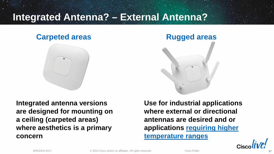
Integrated antenna versions are designed for mounting on a ceiling (carpeted areas) where aesthetics is a primary concern
Use for industrial applications where external or directional antennas are desired and or applications requiring higher temperature ranges
Carpeted areas Rugged areas
97

© 2013 Cisco and/or its affiliates. All rights reserved. BRKEWN-2017 Cisco Public
When to Use Integrated Antennas
When there is no requirement for directional antennas and the unit will ceiling mounted
Areas such as enterprise carpeted office environments where aesthetics are important
When the temperature range will not exceed 0 to +40C
98

© 2013 Cisco and/or its affiliates. All rights reserved. BRKEWN-2017 Cisco Public
When to Use External Antennas Reasons to consider deploying a rugged AP When Omni-directional coverage is not desired or
greater range is needed
The environment requires a more industrial strength AP with a higher temperature rating of -20 to +55 C (carpeted is 0 to +40 C)
The device is going to be placed in a NEMA enclosure and the antennas need to be extended
You have a desire to extend coverage in two different areas with each radio servicing an independent area - for example 2.4 GHz in the parking lot and 5 GHz indoors
Requirement for outdoor or greater range Bridging application (aIOS version)
Requirement for WGB or mobility application where the device is in the vehicle but antennas need to be mounted external Rugged AP in ceiling enclosure
99

© 2013 Cisco and/or its affiliates. All rights reserved. BRKEWN-2017 Cisco Public
Outdoor–rated APs Used for Indoor Applications Harsh environmental conditions (e.g. refrigerated rooms, condensing humidity…)
12V DC powered or 100-480V AC
ATEX Class I Division 2 (potentially explosive areas)
1552i (Integrated Ant) Dual Band Omni AIR-ANT2547V-N=
1552e 100

Installation and Deployment Considerations

© 2013 Cisco and/or its affiliates. All rights reserved. BRKEWN-2017 Cisco Public
Site Survey Prepares for 802.11n
102

© 2013 Cisco and/or its affiliates. All rights reserved. BRKEWN-2017 Cisco Public
Access Point Placement (Legacy a/b/g)
103

© 2013 Cisco and/or its affiliates. All rights reserved. BRKEWN-2017 Cisco Public
Access Point Placement (802.11n)
104

© 2013 Cisco and/or its affiliates. All rights reserved. BRKEWN-2017 Cisco Public
802.11n Support, Backward Compatibility and Co-existence
105
© 2013 Cisco and/or its affiliates. All rights reserved. BRKEWN-2017 Cisco Public
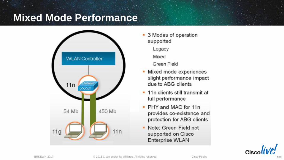
Mixed Mode Performance
106
© 2013 Cisco and/or its affiliates. All rights reserved. BRKEWN-2017 Cisco Public
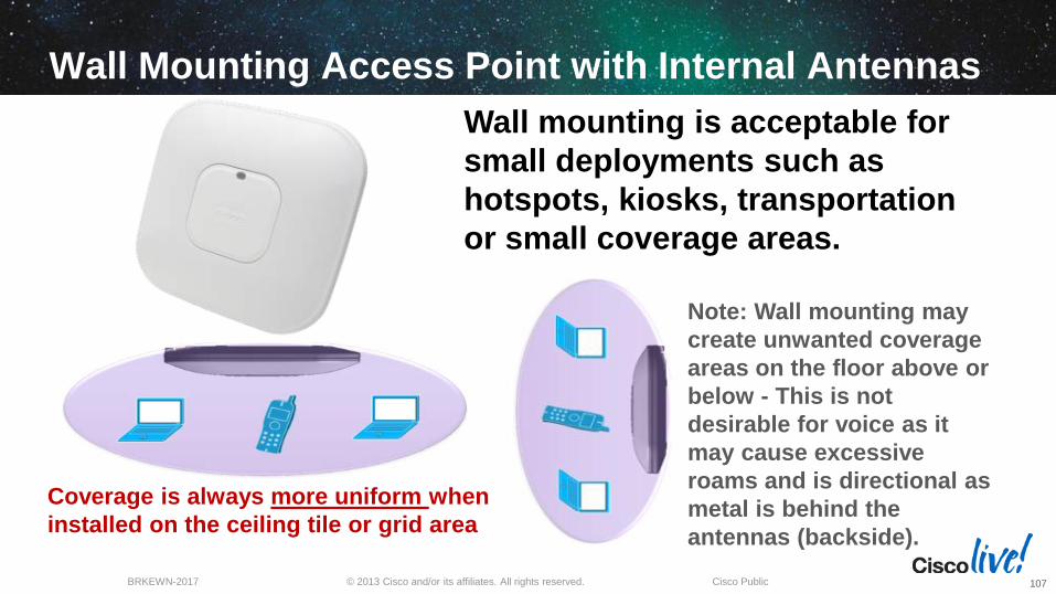
Wall Mounting Access Point with Internal Antennas
Coverage is always more uniform when installed on the ceiling tile or grid area
Note: Wall mounting may create unwanted coverage areas on the floor above or below - This is not desirable for voice as it may cause excessive roams and is directional as metal is behind the antennas (backside).
Wall mounting is acceptable for small deployments such as hotspots, kiosks, transportation or small coverage areas.
107

© 2013 Cisco and/or its affiliates. All rights reserved. BRKEWN-2017 Cisco Public
Access Points 3500i Designed Primarily for Ceiling (Carpeted) Installations
AP-3500 Access Point has six integrated 802.11n MIMO antennas 4 dBi @ 2.4 GHz 3 dBi @ 5 GHz
Note: Metal chassis and antennas were designed to benefit ceiling installations as the signal propagates downward in a 360 degree pattern for best performance
108

© 2013 Cisco and/or its affiliates. All rights reserved. BRKEWN-2017 Cisco Public
Antenna Patterns – Internal Access Points Azimuth and Elevation Patterns for 2.4 GHz & 5 GHz
109
© 2013 Cisco and/or its affiliates. All rights reserved. BRKEWN-2017 Cisco Public
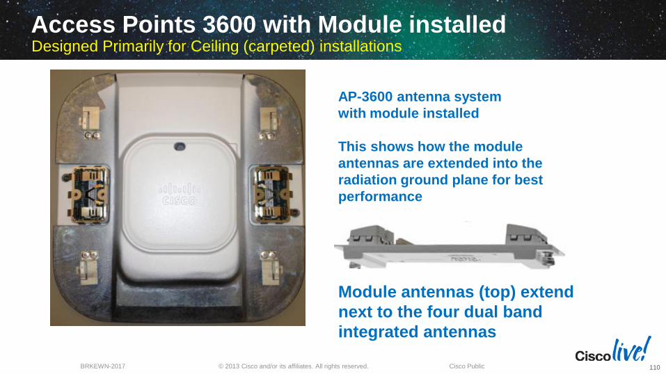
AP-3600 antenna system with module installed This shows how the module antennas are extended into the radiation ground plane for best performance
Module antennas (top) extend next to the four dual band integrated antennas
Access Points 3600 with Module installed Designed Primarily for Ceiling (carpeted) installations
110

© 2013 Cisco and/or its affiliates. All rights reserved. BRKEWN-2017 Cisco Public
Wall mounting AP-1260, 3500e & 3600e Orientation of the Dipoles if Wall Mounting
If using advanced features like location or voice try to locate the AP on the ceiling, or when mounting the AP on a wall orient the dipoles in this configuration. Because dipoles on a wall can easily get orientated wrong as people touch and move them. Better still might be to use a Patch antenna or use the Oberon wall bracket. Be aware walls can add directional properties to the signal as they can have wiring, metal 2x4 construction and the wall attenuates the signal behind the AP limiting a nice 360 degree coverage.
Note: The ceiling is usually higher and a better location for RF.
111

© 2013 Cisco and/or its affiliates. All rights reserved. BRKEWN-2017 Cisco Public
Aironet 802.11n Wall Mount (Style Case) Third Party Wall Mount Option is Available
Oberon model 1029-00 is a right angle mount works with “I” and “e” models http://www.oberonwireless.com/WebDocs/Model1029-00_Spec_Sheet.pdf
This optional wall mount best positions the Access Point dipoles for optimum performance – Recommended for Voice applications If you MUST mount the Access Point on a wall. Ceiling is a better location as the AP will not be disturbed or consider using patch antennas on wall installations
112
© 2013 Cisco and/or its affiliates. All rights reserved. BRKEWN-2017 Cisco Public
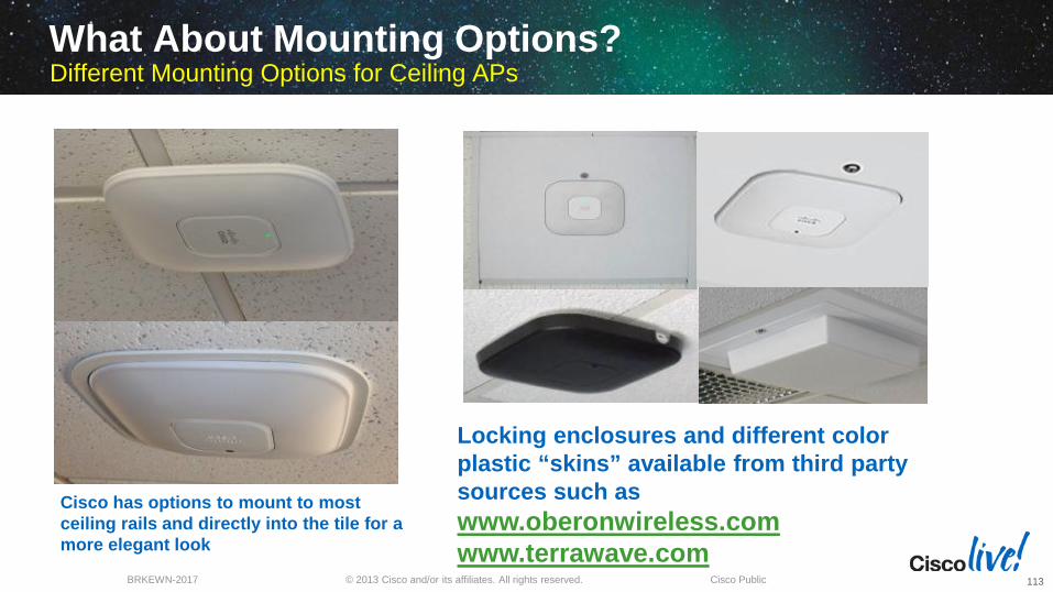
What About Mounting Options? Different Mounting Options for Ceiling APs
Cisco has options to mount to most ceiling rails and directly into the tile for a more elegant look
Locking enclosures and different color plastic “skins” available from third party sources such as www.oberonwireless.com www.terrawave.com
113

© 2013 Cisco and/or its affiliates. All rights reserved. BRKEWN-2017 Cisco Public
Access Point Coverage Comparison 5-GHz up to MCS15
114

© 2013 Cisco and/or its affiliates. All rights reserved. BRKEWN-2017 Cisco Public
Clips Adapt Rail to “T” Bracket. Attaching to Fine Line Ceiling Rails
If the ceiling rail is not wide enough or too recessed for the “T” rail this can be addressed using the optional clips
Part Number for ceiling clips is AIR-ACC-CLIP-20= This item is packaged in 20 pieces for 10 Access Points
115
© 2013 Cisco and/or its affiliates. All rights reserved. BRKEWN-2017 Cisco Public
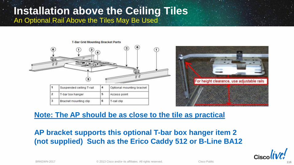
Installation above the Ceiling Tiles An Optional Rail Above the Tiles May Be Used
Note: The AP should be as close to the tile as practical AP bracket supports this optional T-bar box hanger item 2 (not supplied) Such as the Erico Caddy 512 or B-Line BA12
116

© 2013 Cisco and/or its affiliates. All rights reserved. BRKEWN-2017 Cisco Public
AP Placement Above False Ceiling Tiles Areas
When placing the Access Point above the ceiling tiles (Plenum area) Cisco recommends using rugged Access Points with antennas mounted below the Plenum area whenever possible
Cisco antenna have cables that are plenum rated so the antenna can be placed below the Plenum with cable extending into the plenum
If there is a hard requirement to mount carpeted or rugged Access Points using dipoles above the ceiling – This can be done however uniform RF coverage becomes more challenging, especially if there are metal obstructions in the ceiling
Tip: Try to use rugged Access Points and locate the antennas below the ceiling whenever possible
117

© 2013 Cisco and/or its affiliates. All rights reserved. BRKEWN-2017 Cisco Public
Integrated Ceiling Mount – Public Areas
Flush mount bracket part number is AIR-AP-BRACKET-3 This is a Cisco factory bracket that can be specified at time of order Full strut on right provides support across two ceiling rails Making it ideal for safety in (earthquake prone areas)
118

© 2013 Cisco and/or its affiliates. All rights reserved. BRKEWN-2017 Cisco Public
Antenna Placement Considerations
Never mount antennas near metal objects as it causes increased
multipath and directionality
AP antennas need placements that are away from reflective surfaces for best performance
Avoid metal support beams, lighting and other obstructions.
When possible or practical to do so, always mount the Access Point (or remote antennas) as close to the actual users as you reasonably can
Avoid the temptation to hide the Access Point in crawl spaces or areas that compromise the ability to radiate well
Think of the Access Point as you would a light or sound source, would you really put a light there or a speaker there?
119

© 2013 Cisco and/or its affiliates. All rights reserved. BRKEWN-2017 Cisco Public
Wall Mounting AP-1260e, 3500e & 3600e Orientation of the Dipoles if Wall Mounting
120

© 2013 Cisco and/or its affiliates. All rights reserved. BRKEWN-2017 Cisco Public
Wall Mounting AP-1260e, 3500e & 3600e Orientation of the Dipoles if Wall Mounting
Dipoles pointing UP or Down are in vertical polarity This is ideal for uniform coverage.
Dipoles pointing sideways are in horizontal polarity Note: Cisco recommends transmitting antennas use vertical polarity
121

A look at some installations that went wrong

© 2013 Cisco and/or its affiliates. All rights reserved. BRKEWN-2017 Cisco Public
NEVER EVER MIX ANTENNA TYPES Antennas should always cover the same RF cell watch polarity
Installations that Went Wrong
123

© 2013 Cisco and/or its affiliates. All rights reserved. BRKEWN-2017 Cisco Public
When a dipole is mounted against a metal object you lose all Omni-directional properties. It is now essentially a directional patch suffering from acute multipath distortion problems. Add to that the metal pipes and it is a wonder it works at all
Dipole antennas up against a metal box and large metal pipes. This creates unwanted directionality and multipath distortion – This also creates nulls (dead areas) and creates packet retries
Tip: Access Points like light sources should be in the clear and near the users
Above ceiling installs that went wrong Yes it Happens and When it Does it is Expensive to Fix and No One is Happy
124

© 2013 Cisco and/or its affiliates. All rights reserved. BRKEWN-2017 Cisco Public
Above Ceiling Installs that Went Wrong Huh?? You Mean it Gets Worse?
125

© 2013 Cisco and/or its affiliates. All rights reserved. BRKEWN-2017 Cisco Public
Ceiling mount AP mounted on the wall up against metal pipe (poor coverage)
Outdoor NEMA box not weatherized (just keeping the packets on ice)
Other Installations that Went Wrong
126

© 2013 Cisco and/or its affiliates. All rights reserved. BRKEWN-2017 Cisco Public
Mount the box horizontal and extend the antennas down and not right up against the metal enclosure
Patch antenna shooting across a metal fence Multipath distortion causing severe retries
Installations that Went Wrong
127

© 2013 Cisco and/or its affiliates. All rights reserved. BRKEWN-2017 Cisco Public
Sure is a comfy nest – Glad this model runs pretty warm
Installations that Went Wrong
128

© 2013 Cisco and/or its affiliates. All rights reserved. BRKEWN-2017 Cisco Public
GOOD INSTALL
Installations that Went Wrong - Mesh
129
BAD INSTALL

© 2013 Cisco and/or its affiliates. All rights reserved. BRKEWN-2017 Cisco Public
Installations that Went Wrong - Mesh
130

© 2013 Cisco and/or its affiliates. All rights reserved. BRKEWN-2017 Cisco Public
Building aesthetics matters – Antennas obstructed
Installations that Went Wrong - Mesh
131

© 2013 Cisco and/or its affiliates. All rights reserved. BRKEWN-2017 Cisco Public
Outdoor Weatherproofing Coax-Seal can be used with or without electrical tape. Taping first with a quality electrical tape like Scotch 33+ vinyl allows the connection to be taken apart easier. Many people tape then use Coax-Seal then tape again this allows easy removal with a razor blade. Note: Always tape from the bottom up so water runs over the folds in the tape. Avoid using RTV silicone or other caustic material. www.coaxseal.com
132

© 2013 Cisco and/or its affiliates. All rights reserved. BRKEWN-2017 Cisco Public
Summary
“RF Matters”
133
© 2013 Cisco and/or its affiliates. All rights reserved. BRKEWN-2017 Cisco Public
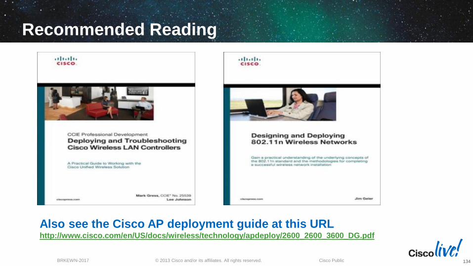
Recommended Reading
“RF Matters” Also see the Cisco AP deployment guide at this URL http://www.cisco.com/en/US/docs/wireless/technology/apdeploy/2600_2600_3600_DG.pdf
134

© 2013 Cisco and/or its affiliates. All rights reserved. BRKEWN-2017 Cisco Public
Maximize your Cisco Live experience with your free Cisco Live 365 account. Download session PDFs, view sessions on-demand and participate in live activities throughout the year. Click the Enter Cisco Live 365 button in your Cisco Live portal to log in.
Complete Your Online Session Evaluation
Give us your feedback and you could win fabulous prizes. Winners announced daily. Receive 20 Cisco Daily Challenge
points for each session evaluation you complete. Complete your session evaluation
online now through either the mobile app or internet kiosk stations.
135


Reference slides… time permitting.
© 2013 Cisco and/or its affiliates. All rights reserved. BRKEWN-2017 Cisco Public
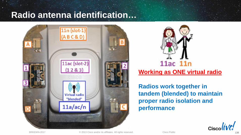
Radio antenna identification…
Working as ONE virtual radio Radios work together in tandem (blended) to maintain proper radio isolation and performance
138

© 2013 Cisco and/or its affiliates. All rights reserved. BRKEWN-2017 Cisco Public
Three separate and discrete radios…
The two 5-GHz radios (integrated and module) work in TANDEM and use same SSIDs so they do not compete with each other. They work in concert to support same channels (with internal radio taking lead on frequency selection) and the module performing the AC “overlay” AP has a dual-core uP with the radio module on one core supporting up to 50 .11ac clients
139
© 2013 Cisco and/or its affiliates. All rights reserved. BRKEWN-2017 Cisco Public
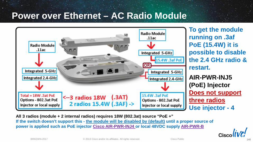
Power over Ethernet – AC Radio Module
All 3 radios (module + 2 internal radios) requires 18W (802.3at) source “PoE +” If the switch doesn’t support this - the module will be disabled by (default) until a proper source of power is applied such as PoE injector Cisco AIR-PWR-INJ4 or local 48VDC supply AIR-PWR-B
To get the module running on .3af PoE (15.4W) it is possible to disable the 2.4 GHz radio & restart. AIR-PWR-INJ5 (PoE) Injector Does not support three radios Use injector - 4
140

© 2013 Cisco and/or its affiliates. All rights reserved. BRKEWN-2017 Cisco Public
You can suspend an AP from the ceiling or use patch or Yagi on walls
Warehouse Design As Stock Levels Change so Does Coverage
141

© 2013 Cisco and/or its affiliates. All rights reserved. BRKEWN-2017 Cisco Public
Warehouse Design As Stock Levels Change so Does Coverage
142
Maximum Tx power Easy power Patch or Yagi antennas Easy Ethernet drop Null spots have to be corrected

© 2013 Cisco and/or its affiliates. All rights reserved. BRKEWN-2017 Cisco Public
Warehouse Design As Stock Levels Change so Does Coverage
143
Reduced Tx power (RRM) More APs (+ power drops) Omni directional antennas AP wire distance to nearest switch
Can difficult to deploy - Placement of APs can be cumbersome

© 2013 Cisco and/or its affiliates. All rights reserved. BRKEWN-2017 Cisco Public
Stadium and Sporting Venues AIR-CAP3502P-x-K9 and AIR-ANT25137-R=
Program to release a new 3500e “style” of AP that is certified for use with a higher gain antenna
Program includes design and development of a new high gain antenna to go with the AP • Aesthetically pleasing • Single radome for both 2.4 and 5 GHz elements
AIR-ANT25137-R= AIR-CAP3502P-x-K9
144
© 2013 Cisco and/or its affiliates. All rights reserved. BRKEWN-2017 Cisco Public
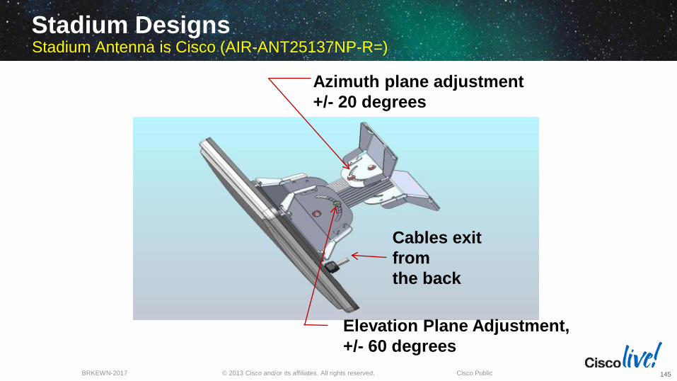
Stadium Designs Stadium Antenna is Cisco (AIR-ANT25137NP-R=)
Azimuth plane adjustment +/- 20 degrees
Elevation Plane Adjustment, +/- 60 degrees
Cables exit from the back
145

© 2013 Cisco and/or its affiliates. All rights reserved. BRKEWN-2017 Cisco Public
Was there a Need for this Antenna?
Discrete antennas for 2.4 GHz and 5 GHz were unsightly and was labor intensive to mount and align.
Yes, part of the problem was the 3500 Series was limited to antenna gains of 6 dBi so we needed a special model AP that could use higher gain antennas (AP-3502P)
Similar performance designed into one housing that supports both 2.4 and 5 GHz MIMO antennas
146

© 2013 Cisco and/or its affiliates. All rights reserved. BRKEWN-2017 Cisco Public
High-Density Design - Bowl
Coverage area divided into cells to support anticipated number of users
Directional antennas create WLAN cells within seating areas
• Lower power, interference
Down-tilt to control the vertical RF beam width
• Lower interference Design and install 2.4 GHz
and 5 GHz
147

© 2013 Cisco and/or its affiliates. All rights reserved. BRKEWN-2017 Cisco Public
Bowl Seating RF Cell Footprint
Overlapping cells should use non-overlapping channels (3 non-overlapping channels in the 2.4 GHz domain)
Radio Resource Management (RRM) automatically sets the AP channel and power
Limitations on where APs can be mounted and pointed influences cell coverage
148


![Wireless USB Adapter User Guide - ALFA1] WiFi USB adapter... · The ALFA WiFi indoor USB adapter provides users to launch IEEE 802.11n/b/g or IEEE 802.11a/an/ac wireless network (depends](https://static.fdocuments.us/doc/165x107/608a1bcd6dac481beb7a6823/wireless-usb-adapter-user-guide-alfa-1-wifi-usb-adapter-the-alfa-wifi-indoor.jpg)