UNDERSTANDING ARCHITECTURAL - … · First In Architecture Contents INTRODUCTION 4 FOUNDATIONS &...
23
UNDERSTANDING ARCHITECTURAL DETAILS - 3 CONCRETE & STEEL CONSTRUCTION Emma Walshaw SAMPLE
Transcript of UNDERSTANDING ARCHITECTURAL - … · First In Architecture Contents INTRODUCTION 4 FOUNDATIONS &...

UNDERSTANDING ARCHITECTURAL DETAILS - 3CONCRETE & STEEL CONSTRUCTION
Emma Walshaw
SAMPLE

The information contained in this ebook is for educational purposes only. All rights reserved. No part of this publication may be reproduced, distributed, or transmitted in any form or by any means, including photocopying, recording, or other electronic or mechanical methods, without the prior written permission from the author.
Users of this guide are advised to use their own due diligence when it comes to working up construction details, and should be verified by qualified professionals.
Under no circumstances should any of the contents of this book be used as construction drawings. Drawings must always be checked and verified by a fully qualified architect or associated professional. The entire contents of this book and associated digital files are for educational purposes only.
Copyright © 2015 by Emma WalshawFirst In Architecture
ContentsINTRODUCTION 4FOUNDATIONS & FLOORS 7BASEMENT DESIGN 55FRAMES 69WALLS 79ROOFS 157INSULATED CONCRETE FORMWORK 201BIBLIOGRAPHY / FURTHER READING 217INDEX 219
SAMPLE

FOUNDATIONS & FLOORS
SECTION 1
SAMPLE

8 SECTION 1 - FOUNDATIONS AND FLOORS
The four main types of foundations in steel and concrete construction are:Strip foundationsPad foundationsRaft foundationsPile foundations
STRIP FOUNDATIONSThe strip foundation consists of a single strip of concrete, which provides a firm and level base for the construction of the walls above. Strip foundations spread the load from walls of brick, masonry or concrete to the subsoil. The foundation depth depends on strength of material, foundation loads and breading capacity of the subsoil.
PRINCIPLES OF FOUNDATION DESIGN
Figure 1.1 - Strip foundation
Detail G01 - Strip foundation
SAMPLE

9
If the subsoil is weak or susceptible to movement the foundation can be taken to a suitable depth where the strata is stronger and able to bear the loads of the proposed structure.
The width of the strip foundation must be adequate that there is room to lay walling material, and also able to spread the loads to a suitable area of subsoil. As a general rule, the projection of the strip each side of the wall should be no greater than the thickness of the concrete.
In other cases, a wide strip foundation may be used to spread the load of the foundation or the strip can be reinforced.
Strip foundations are more commonly used in domestic and residential construction, or more low rise construction.
Figure 1.1 - Strip foundation
Figure 1.2 - Deep strip foundation
Detail G02 - Deep strip foundation
SAMPLE

10 SECTION 1 - FOUNDATIONS AND FLOORS
PAD FOUNDATIONSA pad foundation is generally a square of reinforced concrete, that takes the loading from the column above and transfers it to the ground. The column is positioned centrally on the foundation pad, which requires the pad to be sufficiently reinforced to avoid the point loading of the column punching through the foundation.
The column or pier that sits on the pad foundation can be brick, masonry, concrete or steel. Once again the area of the pad is dependent on strength of subsoil, and loading on the foundation material.
Ground beams are often used to span between the pads and transfer the load of the infill wall to the pads.
Pads can sometimes be linked with concrete strip when they are particularly close together, resulting from a frame that has close spacing.
Detail G03 G04- Simple pad foundation with and without reinforcement
Figure 1.3- Example of a pad foundation with ground beam
SAMPLE

26 SECTION 1 - FOUNDATIONS AND FLOORS
Detail G18 B - Raft foundation with toe - concrete frame - alternative detail
SAMPLE

27
3D Detail G18 B - Raft foundation with toe - concrete frame - alternative detail
SAMPLE

42 SECTION 1 - FOUNDATIONS AND FLOORS
Detail G28 - Beam and block floor - beams parallel to wall, cast in situ concrete downstand
SAMPLE
43
3D Detail G28 - Beam and block floor - beams parallel to wall, cast in situ concrete downstand
SAMPLE
52 SECTION 1 - FOUNDATIONS AND FLOORS
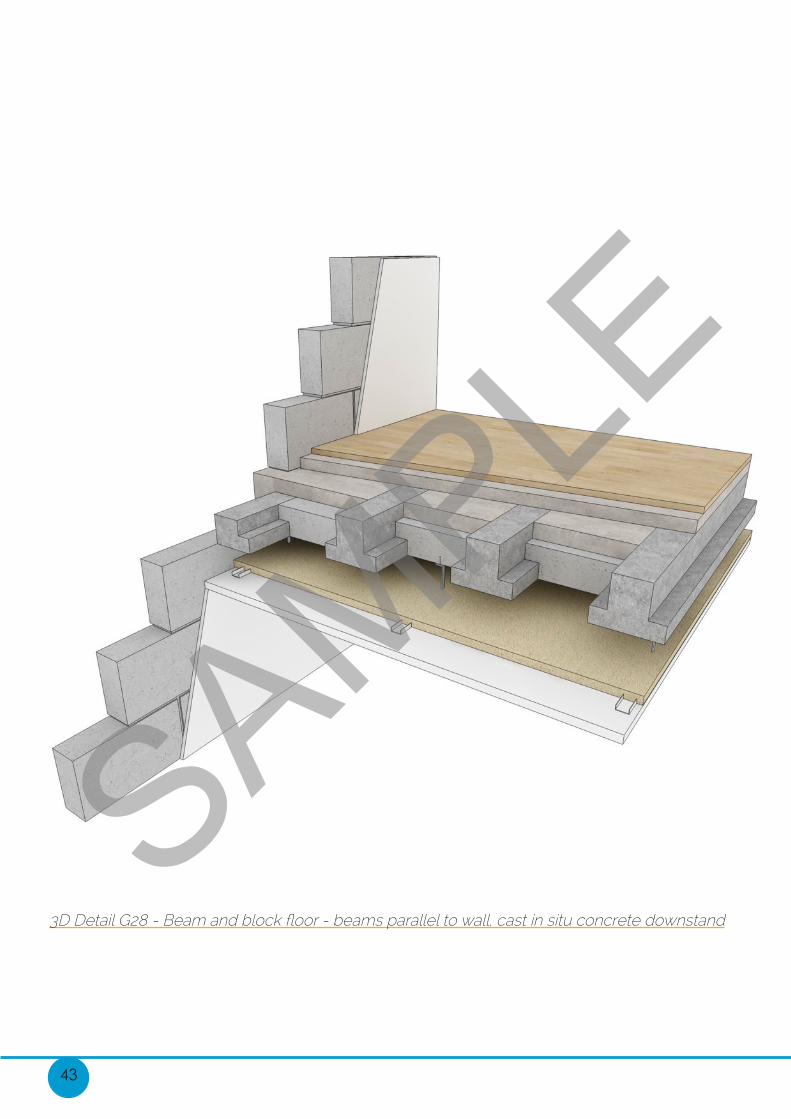
Detail G36 - Solid concrete ground floor - insulation above slab, screed finish underfloor heating
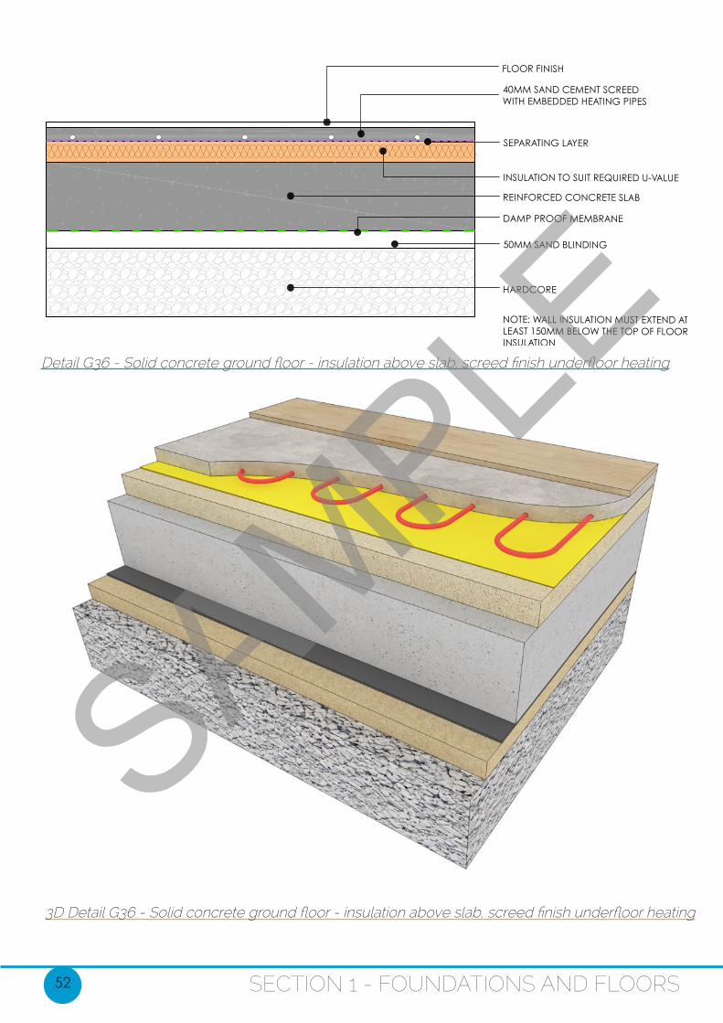
3D Detail G36 - Solid concrete ground floor - insulation above slab, screed finish underfloor heating
SAMPLE

75
TYPES OF FRAMESkeleton Frame:Conventional steel frames are constructed using hot rolled section beams and columns known as a skeleton frame. The skeleton frame supports the whole load of the building - floors, walling, wind pressure and so on. The most economic form of this frame is a standard grid pattern, with a 3m to 4m spacing between columns and floor beams spanning up to 7.5m.
Parallel beam structural steel frame:This type of frame uses spine beams which are fixed on each side of the columns to support secondary beams that support the floor. This also is most economic when designed in a rectangular grid, and main advantages are the ability to integrate services in both directions within the structure.
Figure 3.8 - Example of structural steel skeleton frameSAMPLE
85
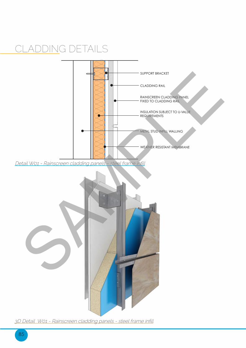
CLADDING DETAILS
Detail W01 - Rainscreen cladding panels - steel frame infill
3D Detail W01 - Rainscreen cladding panels - steel frame infill
SAMPLE
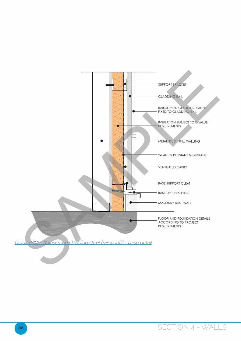
86 SECTION 4 - WALLS
Detail W02 - Rainscreen cladding steel frame infill - base detailSAMPLE
95
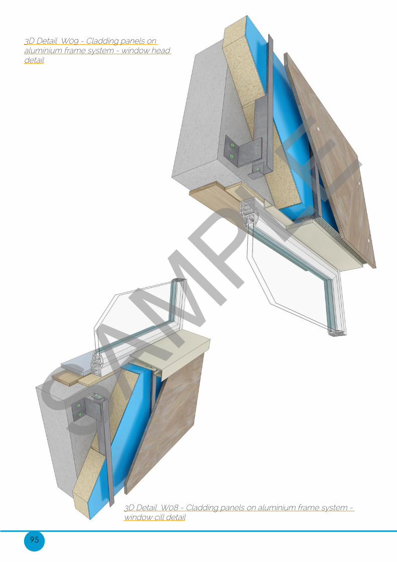
3D Detail W08 - Cladding panels on aluminium frame system - window cill detail
3D Detail W09 - Cladding panels on aluminium frame system - window head detail
SAMPLE
105
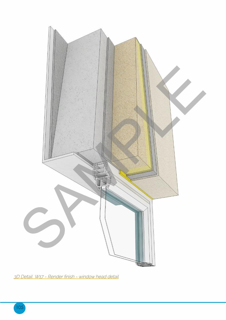
3D Detail W17 - Render finish - window head detail
SAMPLE
161
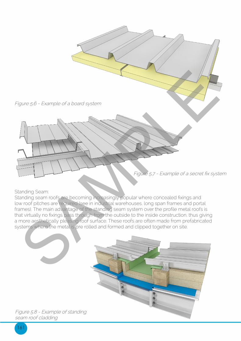
Standing Seam:Standing seam roofs are becoming increasingly popular where concealed fixings and low roof pitches are required (see in industrial warehouses, long span frames and portal frames). The main advantage of the standing seam system over the profile metal roofs is that virtually no fixings pass through from the outside to the inside construction, thus giving a more aesthetically pleasing roof surface. These roofs are often made from prefabricated systems where the metal is pre rolled and formed and clipped together on site.
Figure 5.8 - Example of standing seam roof cladding
Figure 5.6 - Example of a board system
Figure 5.7 - Example of a secret fix system
SAMPLE
188 SECTION 5 - ROOFS
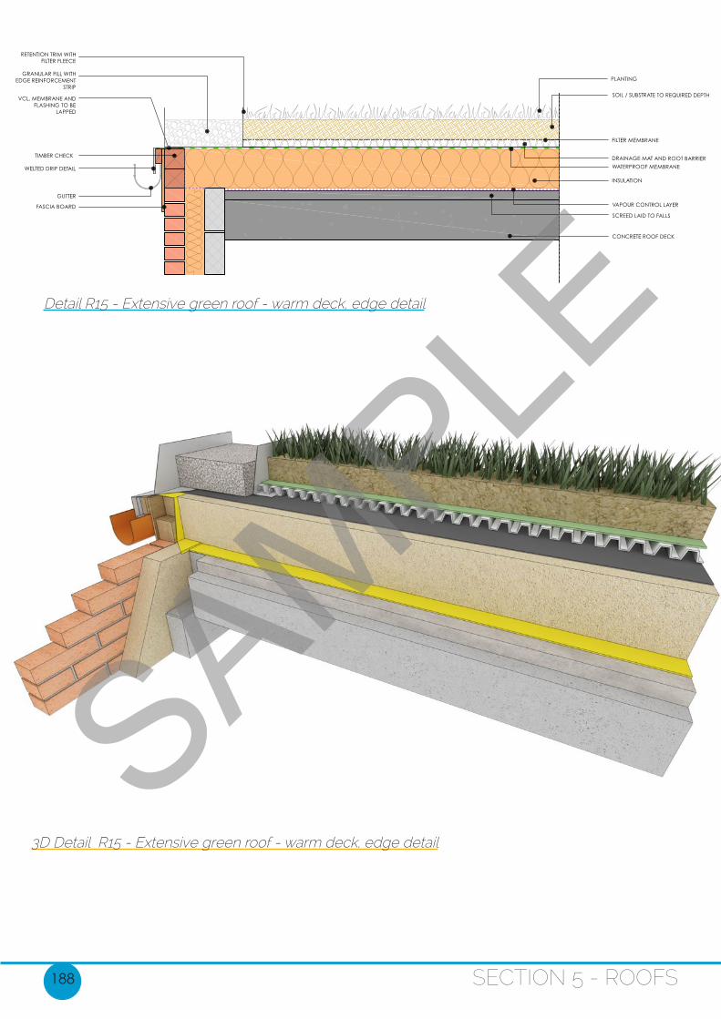
Detail R15 - Extensive green roof - warm deck, edge detail
3D Detail R15 - Extensive green roof - warm deck, edge detail
SAMPLE

206 SECTION 6 - ICF
Detail ICF02 - Strip foundation with ground bearing slab
SAMPLE
207
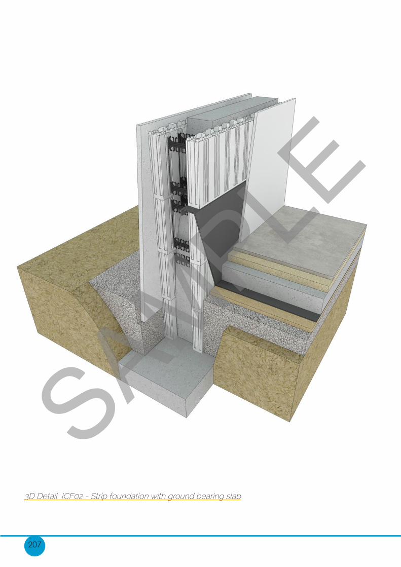
3D Detail ICF02 - Strip foundation with ground bearing slab
SAMPLE
220
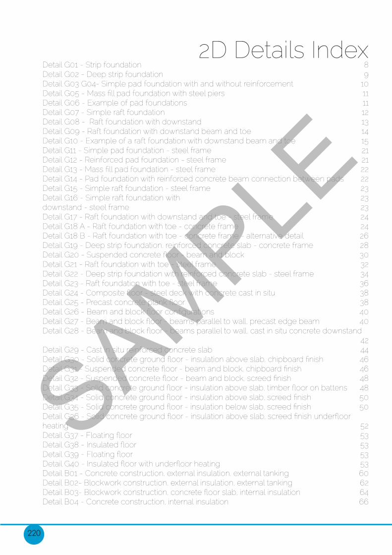
2D Details IndexDetail G01 - Strip foundation 8Detail G02 - Deep strip foundation 9Detail G03 G04- Simple pad foundation with and without reinforcement 10Detail G05 - Mass fill pad foundation with steel piers 11Detail G06 - Example of pad foundations 11Detail G07 - Simple raft foundation 12Detail G08 - Raft foundation with downstand 13Detail G09 - Raft foundation with downstand beam and toe 14Detail G10 - Example of a raft foundation with downstand beam and toe 15Detail G11 - Simple pad foundation - steel frame 21Detail G12 - Reinforced pad foundation - steel frame 21Detail G13 - Mass fill pad foundation - steel frame 22Detail G14 - Pad foundation with reinforced concrete beam connection between pads 22Detail G15 - Simple raft foundation - steel frame 23Detail G16 - Simple raft foundation with 23downstand - steel frame 23Detail G17 - Raft foundation with downstand and toe - steel frame 24Detail G18 A - Raft foundation with toe - concrete frame 24Detail G18 B - Raft foundation with toe - concrete frame - alternative detail 26Detail G19 - Deep strip foundation, reinforced concrete slab - concrete frame 28Detail G20 - Suspended concrete floor - beam and block 30Detail G21 - Raft foundation with toe - steel frame 32Detail G22 - Deep strip foundation with reinforced concrete slab - steel frame 34Detail G23 - Raft foundation with toe - steel frame 36Detail G24 - Composite floor - steel deck with concrete cast in situ 38Detail G25 - Precast concrete plank floor 38Detail G26 - Beam and block floor configurations 40Detail G27 - Beam and block floor - beams parallel to wall, precast edge beam 40Detail G28 - Beam and block floor - beams parallel to wall, cast in situ concrete downstand 42Detail G29 - Cast in situ reinforced concrete slab 44Detail G30 - Solid concrete ground floor - insulation above slab, chipboard finish 46Detail G31 - Suspended concrete floor - beam and block, chipboard finish 46Detail G32 - Suspended concrete floor - beam and block, screed finish 48Detail G33 - Solid concrete ground floor - insulation above slab, timber floor on battens 48Detail G34 - Solid concrete ground floor - insulation above slab, screed finish 50Detail G35 - Solid concrete ground floor - insulation below slab, screed finish 50Detail G36 - Solid concrete ground floor - insulation above slab, screed finish underfloor heating 52Detail G37 - Floating floor 53Detail G38 - Insulated floor 53Detail G39 - Floating floor 53Detail G40 - Insulated floor with underfloor heating 53Detail B01 - Concrete construction, external insulation, external tanking 60Detail B02- Blockwork construction, external insulation, external tanking 62Detail B03- Blockwork construction, concrete floor slab, internal insulation 64Detail B04 - Concrete construction, internal insulation 66
SAMPLE

222
Detail F01 - Long span/portal frame - eaves gutter 145Detail F02 - Long span/portal frame - mono ridge 147Detail F03 - Long span/portal frame - parapet gutter 148Detail F04 - Long span/portal frame - ridge detail 149Detail F05 - Long span/portal frame - door jamb (in plan) 150Detail F06 - Long span/portal frame - external corner (in plan) 151Detail F07 - Long span/portal frame - floor detail 152Detail F08 - Long span/portal frame - window cill 153Detail F09 - Long span/portal frame - window head 154Detail F10- Long span/portal frame - window jamb (in plan) 155Detail R01 - Profiled metal deck 165Detail R02 -Profiled metal deck with concrete topping 166Detail R03- Reinforced concrete warm deck 167Detail R04 -Profiled metal deck parapet junction 168Detail R05 - Concrete deck parapet junction 170Detail R06- Profiled metal deck parapet junction option 172Detail R07- Concealed and protected membrane 174Detail R08 - Exposed single ply membrane 176Detail R09 -Profiled metal deck parapet junction with steel frame wall and structure 178Detail R10 - Steel frame concrete plank floor 180Detail R11 - Standing seam metal roof - ridge detail 182Detail R12 - Standing seam metal roof - mono ridge detail 183Detail R13 - Standing seam metal roof - parapet detail 185Detail R14 - Standing seam metal roof - gutter detail 187Detail R15 - Extensive green roof - warm deck, edge detail 188Detail R16 - Extensive green roof - parapet connection 189Detail R17 - Extensive green roof - parapet detail option 190Detail R18 - Extensive green roof - wall connection 192Detail R19 - Extensive green roof, concrete deck typical build up 194Detail R20- Extensive green roof, metal deck typical build up 196Detail R21 - Extensive green roof - low parapet 198Detail ICF01 - Strip and block foundation with ground bearing slab 204Detail ICF02 - Strip foundation with ground bearing slab 206Detail ICF03 - Precast concrete floor detail 208Detail ICF04 - Window detail 210Detail ICF05 A - Flat roof detail 212Detail ICF05 B - Pitched roof detail 214SAMPLE

www.understandingarchitecturaldetails.co.uk
www.firstinarchitecture.co.uk
All images copyright to ‘Understanding Architectural Details’
End
Note all insulation thicknesses should be calculated in order to achieve required u-values.All structural members should be calculated and assessed by a structural engineer. These drawings MUST NOT be used as construction drawings, and are purely an educational resource. These drawings are not finished or complete construction drawings and should not be used as such. This does not cover CDM regs, and these should always be consulted/considered when drawing up construction documents. SAMPLE