Understanding API SIRE Reading-1 Part 1 of 2
316
Charlie Chong/ Fion Zhang Understandings APIICP-SIRE Reading 1 Part 1 of 2 My Pre-exam self study note for APISIRE-ICP 4 th March 2016
-
Upload
charlie-chong -
Category
Documents
-
view
76 -
download
11
description
Understanding API SIRE Reading-1 Part 1 of 2
Transcript of Understanding API SIRE Reading-1 Part 1 of 2

Charlie Chong/ Fion Zhang
Understandings APIICP-SIRE Reading 1 Part 1 of 2My Pre-exam self study note for APISIRE-ICP 4th March 2016

Charlie Chong/ Fion Zhang
Rotating Equipments

Charlie Chong/ Fion Zhang
Rotating Equipments

Charlie Chong/ Fion Zhang
Rotating Equipments

Charlie Chong/ Fion Zhang
Rotating Equipments

Charlie Chong/ Fion Zhang
Rotating Equipments

Charlie Chong/ Fion Zhang
Rotating Equipments

Charlie Chong/ Fion Zhang
Rotating Equipments

Charlie Chong/ Fion Zhang

Adobe Acrobat Reader HotkeysCtrl + G = find againCtrl + L = full screenCtrl + M = zoom toCtrl + N = go to page (insert number in box)Ctrl + Q = quit programCtrl + + = zoom inCtrl + - = zoom outCtrl + 0 = fit in windowCtrl + 1 = actual sizeCtrl + 2 = fit widthCtrl + 3 = fit visibleCtrl + 4 = reflowCtrl + Shift + A = deselect allCtrl + Shift + F = search queryCtrl + Shift + G = search resultsCtrl + Shift + J = cascade windowsCtrl + Shift + K = tile windows horizontallyCtrl + Shift + L = tile windows vertically
Charlie Chong/ Fion Zhang http://allhotkeys.com/adobe_acrobat_reader_hotkeys.html

Ctrl + Shift + S = save a copyCtrl + Shift + P = page setupCtrl + Shift + W = search word assistantCtrl + Shift + X = search select indexesCtrl + Shift + Page Up = first pageCtrl + Shift + Page Down = last pageCtrl + Shift + + = rotate clockwiseCtrl + Shift + - = rotate counterclockwiseCtrl + Alt + W = close allAlt + Left Arrow = go to previous viewAlt + Right Arrow = go to next viewAlt + Shift + Left Arrow = go to previous documentAlt + Shift + Right Arrow = go to next documentF4 = thumbnailsF5 = bookmarksF8 = hide toolbarsF9 = hide menu bar
http://en.wikipedia.org/wiki/Table_of_keyboard_shortcutshttp://help.adobe.com/en_US/acrobat/using/WS58a04a822e3e50102bd615109794195ff-7aed.w.htmlCharlie Chong/ Fion Zhang

Charlie Chong/ Fion Zhang

Fion Zhang at Xitang4th March 2016
Charlie Chong/ Fion Zhang

Charlie Chong/ Fion Zhang
SME- Subject Matter Expert我们的大学,其实应该聘请这些能干的退休教授. 或许在职的砖头怕被排斥.http://cn.bing.com/videos/search?q=Walter+Lewin&FORM=HDRSC3https://www.youtube.com/channel/UCiEHVhv0SBMpP75JbzJShqw

API SIRE Exam Administration -- Publications Effectivity Sheet -2016Listed below are the effective editions of the publications required for this
exam for the date(s) shown above. Please consult the Guide for Source Inspection and Quality Surveillance of Rotating Equipment for further guidance on specific sections.
Charlie Chong/ Fion Zhang http://www.api.org/Certification-Programs/IndividualCertificationPrograms/Programs

Charlie Chong/ Fion Zhang
API Guide for Source Inspection and Quality Surveillance of Rotating Equipment, October 2015
API Recommended Practice 578, Material Verification Program for New and Existing Alloy Piping Systems, 2nd Edition, March 2010
API Standard 610, Centrifugal Pumps for Petroleum, Petrochemical and Natural Gas Industries, 11th edition, September 2010
API Standard 611, General-Purpose Steam Turbines for Petroleum, Chemical, and Gas Industry Services, 5th edition, September 2008, reaffirmed February 2014
API Standard 614, Lubrication, Shaft-Sealing and Control-Oil Systems and Auxiliaries for Petroleum, Chemical and Gas Industry Services, 5th edition, April 2008
API Standard 617, Axial and Centrifugal Compressors and Expander-compressors for Petroleum, Chemical and Gas Industry Services, 8th edition, September 2014
API Standard 618, Reciprocating Compressors for Petroleum, Chemical, and Gas Industry Services, 5th Edition, December 2007
API Standard 619, Rotary Type Positive Displacement Compressors for Petroleum, Petrochemical and Natural Gas Industries, 5th Edition, December 2010
API Standard 677, General-Purpose Gear Units for Petroleum, Chemical and Gas Industry Services, April 2006, reaffirmed November 2010
API Standard 682, Pumps-Shaft Sealing Systems for Centrifugal and Rotary Pumps, 4th edition, May 2014
http://www.api.org/Certification-Programs/IndividualCertificationPrograms/Programs

Charlie Chong/ Fion Zhang
American National Standards Institute (ANSI)/Hydraulic Institute (HI) HI 14.6, Rotodynamic Pumps for Hydraulic Performance Acceptance Tests, 2011 American Society of Mechanical Engineers (ASME), Boiler and Pressure Vessel Code,
2013 Edition i. Section II Materials, Part A, B, C, D
ii. Section V Nondestructive Examination Definitions in Subsection A, Article 1, Appendix I and Subsection B, Article 30, SE-1316 Articles 1, 2, 4, 5, 6, 7, 9, 10, 23 (section 797 only)
iii. Section VIII Rules for Construction of Pressure Vessels, Division 1 Acceptance Criteria USC 56-57Appendix 7- Examination of Steel Casting iv. Section IX Welding and Brazing Qualifications, Welding only:QW 100-190; QW 200-290. QW 300-380; QW 400-490; QW500-540
American Society of Nondestructive Testing (ASNT) SNT-TC-1A Personnel Qualification and Certification in Nondestructive Testing, 2011
http://www.api.org/Certification-Programs/IndividualCertificationPrograms/Programs

Charlie Chong/ Fion Zhang
American Standard for Testing Materials (ASTM)ASTM A703 Standard Specifications for Steel Castings, General Requirements, for Pressure-Containing Parts, 2015ASTM A182 Standard Specification for Forged or Rolled Alloy and Stainless Steel Pipe Flanges, Forged Fittings, and Valves and Parts for High-Temperature Service, 2015
MSS- Manufacturer Standardization SocietyMSS-SP-55 Quality Standard for Steel Castings for Valves, Flanges, Fittings and Other Piping Components, 2011
SSPC Society for Protective CoatingsSSPC – PA 2 Coating Applications Standard No. 2, Procedure for Determining Conformance to Dry Coating Thickness Requirements, May 2012
SSPC Surface Preparation Guide, the following sections only: SSPC‐SP1 Solvent Cleaning, 2015 SSPC‐SP3 Power Tool Cleaning, 2004 SSPC‐SP5 or NACE 1 White Metal Blast Cleaning, 2006 SSPC‐SP6 or NACE 3 Commercial Blast Cleaning,2006 SSPC‐SP7 or NACE 4 Brush-Off Blast Cleaning, 2006 SSPC‐SP10 or NACE 2 Near-White Blast Cleaning, 2006 SSPC‐SP11 Power Tool Cleaning to Bare Metal, 2012
http://www.api.org/Certification-Programs/IndividualCertificationPrograms/Programs

Charlie Chong/ Fion Zhang

http://www.yumpu.com/zh/browse/user/charliechonghttp://issuu.com/charlieccchong
Charlie Chong/ Fion Zhang

http://greekhouseoffonts.com/Charlie Chong/ Fion Zhang

Charlie Chong/ Fion Zhang
The Magical Book of Tank Inspection ICP

Charlie Chong/ Fion Zhang

Charlie Chong/ Fion Zhang
闭门练功

Charlie Chong/ Fion Zhang
Guide for Source Inspection and Quality Surveillance of Rotating Equipment

Charlie Chong/ Fion Zhang
1.0 Scope/Purpose This study guide covers the process of providing quality surveillance of materials, equipment and fabrications being supplied for use in the oil, petrochemical and gas Industry, including upstream, midstream and downstream segments. This guide may be used as the basis for providing a systematic approach to risk-based source inspection in order to provide confidence that mechanical rotating equipment being purchased meet the minimum requirements as specified in the project documents and contractual agreements. The activities outlined in this study guide do not intend to replace the manufacturer’s own quality system, but rather are meant to guide source inspectors acting on behalf of purchasers to determine whether manufacturers own quality systems have functioned appropriately, such that the purchased equipment will meet contractual agreements.
Charlie Chong/ Fion Zhang
This study guide focuses primarily on Mechanical Rotating Equipment including but not limited to: pumps, gears, compressors, turbines, etc. and associated appurtenances. This document assumes that suppliers/vendors (S/V) have been pre-qualified by a systematic quality review process of their facilities and quality process to determine if the facility has the ability to meet the requirements of the contractual agreements. That process generally leads to a list of pre-approved S/V’s deemed acceptable to the supply chain management of the purchaser and capable of meeting the requirements of the contract prior to it being placed. S/V’s on such a list will normally have an acceptable quality process already in place that meets the requirements of the contract. The purpose of source inspection in such a case is simply to verify that the S/V quality process is working as it should and to verify that certain vital steps in the inspection and test plan (ITP) have been satisfactorily accomplished prior to manufacturing completion and/or shipping.

Charlie Chong/ Fion Zhang
The primary purpose of this study guide is to assist candidates intending to take the API source inspection examination to become certified source inspectors for mechanical rotating equipment. The study guide outlines the fundamentals of source inspection and may be useful to all personnel conducting such activities to perform their jobs in a competent and ethical manner. For more information on how to apply for Source Inspection Certification, please visit API website at http://www.api.org/certification-programs/icp/programs and follow the links as shown in chart below.

Charlie Chong/ Fion Zhang
The Source Inspector Examination contains 100 multiple-choice questions targeting core knowledge necessary to perform source inspection of mechanical rotating equipment. The focus of the exam is on source inspection issues and activities rather than design or engineering knowledge contained in the reference standards. The exam is closed book and administered via computer based testing (CBT). The bulk of the questions address mechanical rotating equipment inspection/ surveillance which are typically known by persons who have experience working as sourceinspectors or persons intending to work as source inspectors who have studied the material in this study guide and the associated reference materials.

Charlie Chong/ Fion Zhang
Pass!

Charlie Chong/ Fion Zhang
2.0 Introduction Like most business processes, the Source Inspection work process follows the Plan–Do–Check–Act (PDCA) circular process first popularized in the 1950’s by Edward Deming. The “Planning” part of source inspection is covered in Sections 6 and 7 of this study guide and involves the source inspection management systems, source inspection project plan and the Inspection and Test Plan (ITP). The “Doing” part is covered in Sections 8 and 9 and involves implementing the ITP, participating in scheduled source inspection work process events, filing nonconformance reports and source inspection report writing. The “Checking” part, covered in Section 8.7, involves looking back at all the source inspection activities that occurred in the Planning and Doing segments to see what went well and what should be improved based on the results of that look-back. And finally the “Act” part (sometimes called the “Adjust” part) covered in Section 8.8 involves implementing all the needed improvements in the “Planning and Doing”process before they are implemented on the next source inspection project.

Charlie Chong/ Fion Zhang
Edward Deming’s PDCA
https://en.wikipedia.org/wiki/W._Edwards_Deming
Charlie Chong/ Fion Zhang
■ The “Planning” involves the source inspection management systems, source inspection project plan and the Inspection and Test Plan (ITP).
■ The “Doing” involves implementing the ITP, participating in scheduled source inspection work process events, filing nonconformance reports and source inspection report writing.
■ The “Checking” involves looking back at all the source inspection activities that occurred in the
Planning and Doing segments to see what went well and what should be improved based on the results of that look-back.
■The “Act” part involves implementing all the needed improvements in the “Planning and Doing”
process before they are implemented on the next source inspection project.

Charlie Chong/ Fion Zhang
3.0 References The following standards or other recommended practices are referenced in this study guide and are the documents from which the SI exam has been developed. API - American Petroleum Institute

Charlie Chong/ Fion Zhang
ASME (ASME International; formerly known as American Society of Mechanical Engineers) Boiler and Pressure Vessel Code (BPVC) Section II—Materials, Parts A, B, C, and D. Section V—Non-destructive Examination (Methods). Section VIII—Division 1 Appendices (Acceptance Criteria). Section IX-Qualification Standard for Welding and Brazing Procedures,
Welders, Brazers, and Welding & Brazing Operators.
Note:• BPVC Section II-Materials-Part A-Ferrous Materials Specifications • BPVC Section II-Materials-Part B-Nonferrous Material Specifications • BPVC Section II-Materials Part C-Specifications for Welding Rods
Electrodes and Filler Metals • BPVC Section II-Materials Part D- Properties (Metric/Customary)

Charlie Chong/ Fion Zhang

Charlie Chong/ Fion Zhang
ASTM 703- CastingASTM 182- ForgingMSSP-SP-55 – Quality for Casting

Charlie Chong/ Fion Zhang
4.0 Definitions, Abbreviations and Acronyms For the purposes of this study guide, the following definitions, abbreviations and acronyms apply.
4.1 AARH Arithmetic Average Roughness Height (a measure of surface roughness).
4,2 Alarm PointPreset value of a parameter at which an alarm warns of a condition requiring corrective action.
4.3 Allowable Operating RegionPortion of a pump's hydraulic coverage over which the pump is allowed to operate, based on vibration within the upper limit of this International Standard or temperature rise or other limitation, specified by the manufacturer.
4.4 Amplitude The magnitude of vibration. Displacement is measured in peak-to-peak. Velocity and acceleration are measured in zero-to-peak or root mean square (rms).

Charlie Chong/ Fion Zhang
Arithmetic Average Roughness Height

Charlie Chong/ Fion Zhang
4.5 Anchor BoltsBolts used to attach the mounting plate to the support structure (concrete foundation or steel structure).
4.6 Annealing Heat TreatmentHeating an object to and then holding it at a specified temperature and then cooling at a suitable rate for such purposes as: reducing hardness, improving machinability, facilitating cold working, producing a desired micro-structure, or obtaining desired mechanical properties.
4.7 ANSI American National Standards Institute.
4.8 API American Petroleum Institute.
4.9 ASMEASME International (formerly known as the American Society of Mechanical Engineers).
4.10 ASNTAmerican Society of Nondestructive Testing.

Charlie Chong/ Fion Zhang
4.11 ASTMASTM International (formerly known as the American Society for Testing and Materials).
4.12 Axially (horizontal) Split Split with the principal joint parallel to the shaft centerline.
4.13 Barrel PumpHorizontal pump of the double-casing type.
4.14 BaseplateA fabricated (or cast) metal structure used to mount, support, and align, machinery and its auxiliary components. Baseplates may be directly grouted to concrete foundations (after proper leveling) or bolted to pre-grouted chockplates.
4.15 Bellows SealType of mechanical seal that uses a flexible metal bellows to provide secondary sealing and spring loading.

Charlie Chong/ Fion Zhang
4.16 BEPFlowrate at which a pump achieves its highest efficiency at rated impeller diameter. Note: Best Efficiency Pointhttp://www.engineeringtoolbox.com/best-efficiency-point-bep-d_311.html
4.17 BHPBrake Horsepower. The actual amount of horsepower being consumed by the rotating equipment.
4.18 BladesRotating air foils for both compressors and turbines unless modified by an adjective.

Charlie Chong/ Fion Zhang
BEP

Charlie Chong/ Fion Zhang
4.19 BOKBody of Knowledge (in this case the BOK for the Source Inspectorexamination).
4.20 Booster Pump Oil pump that takes suction from the discharge of another pump to provide oil at a higher pressure.
4.21 BPVC Boiler and Pressure Vessel Code (published by ASME).
4.22 Buffer FluidExternally supplied fluid, at a pressure lower than the pump seal chamber pressure, used as a lubricant and/or to provide a diluents in an Arrangement 2 seal.
Charlie Chong/ Fion Zhang
4.23 Certification Documented and signed testimony of qualification. Certification generally refers to the confirmation of certain, specified characteristics of a product or confirmation of a person meeting requirements for a specific qualification.
4.24 Calibration A comparison between measurements—one of known magnitude or correctness (the standard) compared to the measuring device under test in order to establish the accuracy of a measuring device.
4.25 Cartridge Seal Completely self-contained unit (including seal/rings, mating ring/s, flexible elements, secondary seal, seal gland plate, and sleeve) that is preassembled and preset before installation.
4.26 Circulating Oil System A system which withdraws oil from the housing of bearings equipped with oil rings and cools it in an external oil cooler before it is returned to the bearing housing.

Charlie Chong/ Fion Zhang
4.27 Cladding A metal integrally bonded onto another metal (e.g. plate), under high pressure and temperature whose properties are better suited to resist damage from the process fluids than the underlying base metal.
4.28 Cold WorkingPlastic deformation (forming, rolling, forging, etc.) of metals below the recrystallization temperature of the metal.
4.29 Coast Down Time Period required after the driver is tripped for the equipment to come to rest.
4.30 Compressor Rated Point The intersection on the 100% speed curve corresponding to the highest capacity of any specified operating point.
4.31 ConsoleTotal system whose components and controls are packaged as a single unit on a continuous or joined baseplate.

Charlie Chong/ Fion Zhang
Compressor Rated Point

Charlie Chong/ Fion Zhang
4.32 CrThe chemical symbol for chromium which may appear on an MTR.
4.33 Critical Equipment Equipment that has been risk assessed and determined that if it were to fail in service, it would have an unacceptable impact on process safety,environment, or business needs and therefore deserves a higher level of source inspection attention to make sure the equipment being delivered is exactly as specified.
4.34 Critical ServiceCritical service is typically defined as those applications that are unspared/single-train installations whereby loss of operation would result in significant loss of production, loss of primary process containment, or threat to personnel safety.
4.35 Critical SpeedShaft rotational speed at which the rotor-bearing-support system is in a state of resonance.
4.36 CuThe chemical symbol for copper which may appear on a MTR.

Charlie Chong/ Fion Zhang
4.37 Datum Elevation Elevation to which values of NPSH are referred.
4.38 Destructive Testing Various tests that are performed on metals for the purposes of determining mechanical properties and which involve testing (usually breaking) of sample coupons. Examples of such tests include tensile testing, bend testing and Charpy impact testing. A destructive testing work process involves extracting samples /coupons from components and testing for characteristics that cannot otherwise be determined by nondestructive testing. The work process involves breaking and/or testing coupons/ samples to failure, thus usually rendering the component from which the samples were extracted unfit for continued service.
4.39 Deviation A departure from requirements in the contractual agreements or its referenced PO, engineering design, specified codes, standards or procedures.
4.40 DFT Dry Film Thickness (of paint and coatings) which is measured by a DFT gauge.

Charlie Chong/ Fion Zhang
4.41 Displacement A vibration measurement that quantifies the amplitude in engineering units of mils (1 mil = 0.001 in.) or micrometers.
4.42 Double Casing Type of pump construction in which the pressure casing is separate from the pumping elements contained in the casing.
4.43 Drive-Train Component Item of the equipment used in series to drive the pump.
4.44 Dwell TimeThe total time that the penetrant or emulsifier is in contact with the test surface, including the time required for application and the drain time.
4.45 Electrical RunoutA source of error on the output signal from a non-contacting probe system resulting from non-uniform electrical conductivity properties of the observed material or from the presence of a local magnetic field at a point on the shaft surface.

Charlie Chong/ Fion Zhang
Double Casing

Charlie Chong/ Fion Zhang
Mechanical RunoutRun-out or runout is an inaccuracy of rotating mechanical systems, specifically that the tool or shaft does not rotate exactly in line with the main axis. For example; when drilling, run-out will result in a larger hole than the drill's nominal diameter due to the drill being rotated eccentrically (off axis instead of in line). In the case of bearings, run-out will cause vibration of the machine and increased loads on the bearings.[1]
Run-out is dynamic and cannot be compensated. If a rotating component, such as a drill chuck, does not hold the drill centrally, then as it rotates the rotating drill will turn about a secondary axis.
Run-out has two main forms:Radial run-out is caused by the tool or component being rotated off centre, i.e. the tool or component axis does not correspond with the main axis. Radial run-out will measure the same all along the main axis.Axial run-out is caused by the tool or component being at an angle to the axis. Axial run-out causes the tip of the tool (or shaft) to rotate off centre relative to the base. Axial run-out will vary according to how far from the base it is measured.

Charlie Chong/ Fion Zhang
In addition, irregular run-out is the result of worn or rough bearings which can manifest itself as either axial or radial run-out.
Runout will be present in any rotating system and, depending on the system, the different forms may either combine increasing total runout, or cancel reducing total runout. At any point along a tool or shaft it is not possible to determine whether runout is axial or radial; only by measuring along the axis can they be differentiated.
Absolute alignment is not possible; a degree of error will always be present.

Charlie Chong/ Fion Zhang
Electrical RunoutElectrical runout ( ERO) reflects the heterogeneity of electromagnetic characteristics on surface of shaft. On-site measurement can inspect whether the ERO satisfies the processing and the machine operating requirements. It is very important for controlling the product quality and ensuring the working property. An on-site measurement technology of ERO on shaft based on eddy current was presented. Firstly, the working principle of eddy current sensor and the distribution of eddy were introduced. Then, a finite element analytical model for measuring ERO was developed. Finally, an onsite measurement system was set up to measure the ERO of air compressor main shaft. The results verify the validity of measurement system.
http://www.runout.us/

Charlie Chong/ Fion Zhang
Measurement of Runout:Vibration measurement of rotating components is well known and largely understood due to online vibration monitoring systems such as Prosig’sPROTOR system. One major component of such systems is the ability to measure shaft vibration using non-contact probes such as eddy-current shaft proximity probes. These probes measure the distance between the probe tip and the shaft surface. One important aspect to be aware of when using this type of probe is a phenomenon known as Runout. The DATS Rotor RunoutMeasurement option allows easy measurement of runout.
Runout is the combination of the inherent vibration measurement of a rotating object together with any error caused by the measurement system. Runoutmay consist of two components:
■ Mechanical Runout – An error in measuring the position of the shaft centerline with a displacement probe that is caused by out-of-roundness and surface imperfections.
■ Electrical Runout – An error signal that occurs in eddy current displacement measurements when shaft surface conductivity varies.
http://prosig.com/portfolio/dats-rotor-runout-measurement/

Charlie Chong/ Fion Zhang
Measurement of Runout:
http://prosig.com/portfolio/dats-rotor-runout-measurement/

Charlie Chong/ Fion Zhang
Measuring Shaft Runout on Electric MotorsShaft Runout Tolerances & StandardsWhat is meant by mechanical runout? It is the measure of a shaft's deviation from an absolute uniform radius as the circumference of the shaft is traversed.
Mechanical runout is frequently the result of machining processes such as lobing, tool chatter, and/or improper feed rate and speed of the cutting tools; dents from handling; patches of rust; bowed rotor; and defective or worn bearings in the supports of the machine or lathe.
A proximity probe will measure both (1) mechanical and (2) electrical runoutin which case the whole measurement is known as TIR or “Total Indicated Runout”. In order to bring TIR within acceptable tolerances, mechanicalrunout must be mitigated prior to addressing electrical runout. One must make a precise measurement of the physical profile of the shaft in order to ascertain mechanical runout. Mechanical runout should be measured with an electronic dial indicator with digital readout or a LVDT (Linear Variable Differential Transformer) 线性可变差动变压器 for accuracy. Either of these tools is capable of resolving increments as small or smaller than 0.1mil, rendering the more commonly owned mechanical dial indicator impractical.
http://www.tigertek.com/servo-motor-resources/shaft-runout-on-electric-motors.html

Charlie Chong/ Fion Zhang
LVDT (Linear Variable Differential Transformer)线性可变差动变压器
http://www.composelec.com/linear_variable_differential_transformer.php

Charlie Chong/ Fion Zhang
It is common practice when performing machinery diagnostics is to subtract a known runout signal from the overall vibration waveform to obtain a "runout-free" waveform. Known as compensation, it is a way of dealing with both mechanical and electrical runout. Compensation can be valuable as the runout signal can generally be validated and updated as needed as part of the diagnostic process but is not recommended as part of a permanent monitoring system since runout signals can change over time and skew true results. These changes are most often due to surface scratches incurred during operation or maintenance, and/or changes in the amount and distribution of shaft magnetism. Therefore, compensation could be used for diagnostics only and not for ongoing machinery protection.
http://www.tigertek.com/servo-motor-resources/shaft-runout-on-electric-motors.html

Charlie Chong/ Fion Zhang
Standards for new and refurbished motors are set by the American Petroleum Institute (API) and are frequently cited. Generally, API specifications require that the shaft be supported in v-blocks; the probe be perpendicular to one face of the v-block; and that runout be measured in terms of peak-to-peak probe output. For example, API Standard 687 (Repair of Special Purpose Rotors) provides a very detailed description of how to measure runout.
Standard 612 (Petroleum, Petrochemical and Natural Gas Industries - Steam Turbines - Special-purpose Applications) deals with TIR requirements of mechanical drive steam turbines, requiring the TIR to be 0.25 mil pp or 25% of allowable vibration, whichever is greater. API 617 (Axial and Centrifugal Compressors and Expander-compressors for Petroleum, Chemical and Gas Industry Services) has identical runout requirements dealing specifically with process centrifugal and axial compressors as well as turbo-expanders while API Standard 670 (Machinery Protection Systems) deals with the subject of using compensation in permanent monitoring systems.
http://www.tigertek.com/servo-motor-resources/shaft-runout-on-electric-motors.html

Charlie Chong/ Fion Zhang
Mechanical Runout : An error in measuring the position of the shaft centerline with a displacement probe that is caused by out-of-roundness and surface imperfections.
Electrical Runout : An error signal that occurs in eddy current displacement measurements when shaft surface conductivity varies.

Charlie Chong/ Fion Zhang
4.46 Elevation The height of any point on a vessel, structure, or assembly as shown on a drawing e.g. nozzle, manway, or longitudinal weld as measured from a base plate or other reference line.
4.47 Employer The corporate, public or private entity which employs personnel for wages, salaries, fees or other considerations e.g. the employer of the source inspector.
4.48 Engineered Equipment Equipment that is custom designed and engineered by the client and/or EPC to perform a project-specific function. Engineered equipment will typically require more source inspection than non-engineered equipment.
4.105 Non-engineered Equipment Equipment that is designed and fabricated by S/V’s, which includes off-the-shelf items such as valves, fittings, as well as some skid units, instruments, pumps and electrical gear. Such equipment is usually purchased by catalog model numbers, etc. Non-engineered equipment will typically require less source inspection than engineered equipment.

Charlie Chong/ Fion Zhang
4.49 EPCEngineering/Procurement/Construction contract company.
4.50 Equipment Train Two or more rotating equipment machinery elements consisting of at least (1) one driver and (2) one driven element joined together by a coupling.

Charlie Chong/ Fion Zhang
Equipment Train

Charlie Chong/ Fion Zhang
4.51 Examiner A person who performs specified nondestructive examination (NDE) on components and evaluates the results to the applicable acceptance criteria to assess the quality of the component. Typically NDE examiners (sometimes called NDE technicians) are qualified to ASNT NDE personnel qualification practices e.g. SNT-TC-IA or CP-189.
4.52 FeThe chemical symbol for iron which may appear on an MTR.
4.53 Ferrous MaterialsAlloys that are iron based, including stainless steels.
4.54 FlushFluid that is introduced into the seal chamber on the process fluid side in close proximity to the seal faces and typically used for cooling and lubricating the seal faces and/or to keep them clean.
4.55 GearRefers to either the pinion or gear wheel.

Charlie Chong/ Fion Zhang
Pinion Or Gear Wheel

Charlie Chong/ Fion Zhang
4.56 Gear Rated Power The maximum power specified by the purchaser on the data sheets and stamped on the nameplate.
4.57 Gear-Service Factor (sf)The factor that is applied to the tooth pitting index and the bending stress number, depending upon the characteristics of the driver and the driven equipment, to account for differences in potential overload, shock load, and/or continuous oscillatory torque characteristics.

Charlie Chong/ Fion Zhang
Gear Rated Power

Charlie Chong/ Fion Zhang
4.588 Gear WheelThe lowest speed rotor in a gearbox.
4.59 Gearing The pinion(s) and gear wheel combination(s). A gear mesh is a pinion and gear wheel that operates together. A gear wheel may mesh with more than one pinion, and therefore be part of more than one gear mesh.
4.60 General Purpose Usually spared or in non-critical service.
4.61 HAZHeat Affected Zone, the area of base metal directly adjacent to the weld that has had its metal structure affected by the heat of welding.
4.62 Hot WorkingPlastic deformation (forming, rolling, forging, etc.) of metals at a temperature above the metal recrystallization temperature.
4.63 Hunting Tooth Combination Exists for mating gears when a tooth on the pinion does not repeat contact with a tooth on the gear until it has contacted all the other gear teeth.

Charlie Chong/ Fion Zhang
Pinion & Gear Ring

Charlie Chong/ Fion Zhang
4.64 Hydrodynamic BearingsBearings that use the principles of hydrodynamic lubrication.
4.65 ICPIndividual Certification Program (of the API) under which this source inspector certification program is administered.
4.66 Inlet Volume Flow Flow rate expressed in volume flow units at the conditions of pressure, temperature, compressibility and gas composition, including moisture content, at the compressor inlet flange.
4.67 Inspection The evaluation of a component or equipment for compliance with a specific product specification, code, drawing and/or standard specified in the contractual requirements, which may include the measuring, testing or gauging of one or more characteristics specified for the product to determine conformity.

Charlie Chong/ Fion Zhang
4.68 Inspection Coordinator Individual who is responsible for the development of the source inspection strategy, coordination of the source inspection visits, and implementation of the source inspection activities on a project.
4.69 Inspection Waiver Permission to proceed with production/shipment without having a purchaser source inspection representative present for a specific activity.
4.70 ITPInspection and Test Plan—A detailed plan (checklist) for the source inspection activities which will guide the source inspector in his/her quality assurance activities (QA) at the S/V site with reference to applicable technical information, acceptance criteria and reporting information. The supplier/vendor should also have their own ITP to guide their fabrication personnel and quality assurance personnel (QA) in the necessary quality steps and procedures.

Charlie Chong/ Fion Zhang
4.71 LaminationA type of discontinuity with separation or weakness generally aligned parallel to the worked surface of a plate material. In a forging it can rise to the surface or occur internally; it is generally associated with forging at too low of a temperature or in plate material may be caused by the tramp elements that have congregated in the center of the plate during rolling.
4.72 Leakage rateVolume or mass of fluid passing through a seal in a given length of time.
4.73 Levelness The position of a surface of a component or structure that is horizontal (within tolerances) with the base plate and at 90 degrees to the vertical plumb line. Nozzle and attachment levelness tolerances are not addressed in ASME BPVC Section VIII, Division 1; however, in the pressure vessel hand-book, a ½ tolerance is permissible. For levelness checking of a nozzle on a vessel, a level gauge is used. If the bubble is in the middle of the designated lines, the nozzle is level. A level gauge would be used for verification and measurement that the angle of a hill-side (tangential) nozzle is properly installed relative to the vessel centerline.
Charlie Chong/ Fion Zhang
4.74 MAWP Maximum Allowable Working Pressure; maximum continuous pressure for which the manufacturer has designed the rotating equipment (or any part to which the term is referred) when operating on the specified liquid or gas at the specified maximum operating temperature (does not include mechanical seal).
4.75 ManufacturerThe organization responsible for the design and manufacture of the equipment.
4.76 Maximum Allowable Continuous Rod LoadThe highest combined rod load at which none of the forces in the running gear (piston, piston rod, crosshead assembly, connecting rod, crankshaft, bearings etc.) and the compressor frame exceed the values in anycomponent for which the manufacturer’s design permits continuous operation.

Charlie Chong/ Fion Zhang
4.77 Maximum Allowable Speed Highest speed at which the manufacturer's design permits continuous operation.
4.78 Maximum Allowable Temperature Maximum continuous temperature for which the manufacturer has designed the pump (or any part to which the term is referred) when pumping the specified liquid at the specified maximum operating pressure.
4.79 Maximum Continuous SpeedThe speed at least equal to 105% of the highest speed required by any of the specified operating conditions.
4.80 Maximum Discharge pressureMaximum specified suction pressure plus the maximum differential pressure the pump with the furnished impeller is able to develop when operating at rated speed with liquid of the specified normal relative density (specific gravity).

Charlie Chong/ Fion Zhang
Maximum Continuous Speed The speed at least equal to 105% of the highest speed required by any of the specified operating conditions.

Charlie Chong/ Fion Zhang
Maximum Discharge pressureMaximum specified suction pressure + the maximum differential pressure the pump with the furnished impeller is able to develop.
suction pressure
differential pressure
suction
Discharge

Charlie Chong/ Fion Zhang
4.81 Maximum Exhaust Casing Pressure The highest exhaust steam pressure that the purchaser requires the casing to contain, with steam supplied at maximum inlet conditions.
4.82 MgThe chemical symbol for magnesium which may appear on an MTR.
4.83 MnThe chemical symbol for manganese which may appear on an MTR.
4.84 MoThe chemical symbol for molybdenum which may appear on an MTR.
4.85 Mechanical Runout (see electrical runout)A source of error in the output signal of a proximity probe system resulting from surface irregularities, out-of-round shafts, and such.

Charlie Chong/ Fion Zhang
4.86 Minimum Allowable Speed Lowest speed at which the manufacturer's design permits continuous operation.
4.87 Minimum Allowable Suction Pressure The lowest pressure (measured at the inlet flange of the cylinder) below which the combined rod load, gas load, discharge temperature, or crankshaft torque load (whichever is governing) exceeds the maximum allowable value during operation at the set pressure of the discharge relief valve and other specified inlet gas conditions for the stage.
4.88 Minimum Continuous Stable Flow Lowest flow at which the pump can operate without exceeding the vibration limits imposed by this International Standard.
4.89 Minimum Exhaust PressureThe lowest exhaust steam pressure at which the turbine is required to operate continuously.

Charlie Chong/ Fion Zhang
4.90 Minimum Inlet PressureThe lowest inlet steam pressure and temperature conditions at which the turbine is required to operate continuously.
4.91 Misalignment The degree to which the axes of machine components are non-collinear, either in (1) offset or (2) angularity.
4.92 Mounting Plates A structure (baseplate or a mounting plate), with machined surfaces, to allow the mounting and accurate alignment of items of equipment, which may or may not operate.
4.93 MSSManufacturers Standardization Society.
4.94 Maximum Static Sealing Pressure Highest pressure, excluding pressures encountered during hydrostatic testing, to which the seals can be subjected while the pump is shut down.

Charlie Chong/ Fion Zhang
4.95 MT Magnetic Particle Testing (Examination).
4.96 MTR Material Test Report or Mill Test Report—A document that certifies that a metal/material product is in conformance with the requirements (e.g. chemical and mechanical properties) of a specified industry standard—such as ASTM, ASME, etc.
4.97 Multistage PumpPump with three or more stages.
4.98Nb The chemical symbol for niobium which may appear on an MTR.
4.99 NCRNonconformance Report—A report filled out by the SI detailing an issue that has been discovered to be not in accordance with project contractual agreements such as the (1) PO, (2) engineering design, (3) specified codes, (4) standards or (5) procedures.

Charlie Chong/ Fion Zhang
4.100 NDE MapA drawing which identifies specific locations where NDE has been conducted on a product/component.
4.101 NDE/NDTNondestructive Examination (the preferred terminology)/Non-destructive Testing (the outdated terminology). A quality process that involves the examination, testing and evaluation of materials, components or assemblies without affecting its functionality e.g. VT, PT, MT, UT, and RT.
4.102 NDTNondestructive Testing—Means the same as NDE, which is now the preferred terminology.
4.103 NiThe chemical symbol for nickel which may appear on an MTR.

Charlie Chong/ Fion Zhang
4.104 Nonconformance A departure/deviation from project contractual agreements such as the PO, engineering design, specified codes, standards or procedures.
4.105 Non-engineered EquipmentEquipment that is designed and fabricated by S/V’s, which includes off-the-shelf items such as valves, fittings, as well as some skid units, instruments, pumps and electrical gear. Such equipment is usually purchased by catalog model numbers, etc. Non-engineered equipment will typically require less source inspection than engineered equipment.
4.48 Engineered Equipment Equipment that is custom designed and engineered by the client and/or EPC to perform a project-specific function. Engineered equipment will typically require more source inspection than non-engineered equipment.
4.106 Non-ferrous Materials Alloys that are not iron based e.g. nickel and copper based alloys.

Charlie Chong/ Fion Zhang
4.107 Normalizing Heat TreatmentA heat treating process in which a ferrous material or alloy is heated to a specified temperature above the transformation range of the metal and subsequently cooled in still air at room temperature. Typically normalizing heat treatments will refine the grain size and improve the impact properties of steels.
4.108 NPS Nominal Pipe Size—A standard for designating pipe sizes (inches) and associated wall thickness (schedule) e.g. the nominal pipe size for a four inch pipe is normally shown as NPS 4.
4.109 NPSHaNPSH determined by the purchaser for the pumping system with the liquid at (1) the rated flow and (2) normal pumping temperature.
4.110 NPSHrNPSH that results in a 3% loss of head (first-stage head in a multistage pump) determined by the vendor by testing with water.

Charlie Chong/ Fion Zhang
4.111 Normal Operating ConditionThe condition at which usual operation is expected and optimum efficiency is desired. This condition is usually the point at which the vendor certifies that performance is within the tolerances stated in this standard.
4.112 Normal Operating Point Point at which usual operation is expected and optimum efficiency is desired. This point is usually the point at which the vendor certifies the heat rate is within the tolerances stated in this standard.
4.113 Normal Transmitted PowerThe power at which usual operation is expected and optimum efficiency is desired. The normal transmitted power may be equal to or less than the gear-rated power.
4.114 Nozzles Turbine stationary (non-rotating) airfoils.(?)

Charlie Chong/ Fion Zhang
Turbine Foils

Charlie Chong/ Fion Zhang
4.115 Oil Mist Lubrication Lubrication provided by oil mist produced by atomization and transported to the bearing housing, or housings, by compressed air.
4.116 Observed Inspection (Observed test) (non-hold point?)Inspection or test where the purchaser is notified of the timing of the inspection or test and the inspection or test is performed as scheduled, regardless of whether the purchaser or his representative is present.
4.117 Open Cycle One which the working medium enters the gas turbine from the atmosphere and discharges to the atmosphere directly or indirectly through exhaust heat recovery equipment.
4.118 Operating RegionPortion of a pump's hydraulic coverage over which the pump operates.
4.119 Overhung Pump Pump whose impeller is supported by a cantilever shaft from its bearing assembly.

Charlie Chong/ Fion Zhang
Oil Mist Lubrication

Charlie Chong/ Fion Zhang
Oil Mist Lubrication

Charlie Chong/ Fion Zhang
Overhung PumpThe impeller(s) is mounted on the end of a shaft which is cantilevered or “overhung”from its bearing supports.

Charlie Chong/ Fion Zhang
Multistage Overhung Pump

Charlie Chong/ Fion Zhang
4.120 P The chemical symbol for phosphorus which may appear on an MTR.
4.121 Peak to Peak Value The difference between positive and negative extreme values of an electronic signal or dynamic motion.
4.122 Pinion The high-speed rotor(s) in a gearbox/gearset.

Charlie Chong/ Fion Zhang
4.123 Piston Rod Drop A measurement of the position of the piston rod relative to the measurement probe mounting location(s) (typically oriented vertically at the pressure packing on horizontal cylinders).

Charlie Chong/ Fion Zhang
Rod DropThe vast majority of Reciprocating Compressors are designed with horizontal Cylinders and
Pistons. This is primarily due to foundation requirements and the popularity of opposed-balanced machine designs.
The force of gravity causes the Piston to "RIDE" more in the bottom of the Cylinder than in the top. In turn, this causes the Piston to wear more in the "DOWN" direction. Machine manufactures provide wear or rider rings to provide a replaceable wearing surface. For lubricated Cylinders, glass embedded Teflon may be used. For non-lubricated Cylinders, Teflon may be used.
The wear or rider rings are allowed to wear sacrificially. They are rotated or replaced before damage to the Cylinder lining occurs. There are several methods used to determine when to replace or rotate the rings. One method is to operate a new machine for a given number of hours or days. Then a valve is removed, and the wear is measured by using a feeler gauge. A calculation is then performed with this information. The results determine the length of time the machine can be safely operated with periodic inspections of the rings. Obviously, this is a very frustrating method of performing preventative maintenance.
Currently, one popular safety device for detecting Rod Drop is a unit mounted under the rod at a gap determined by the allowable wear of the wear ring. When the rod contacts the safety unit white metal is worn through allowing instrument air to escape. This in turn causes a pneumatic flag on the control panel to change status.
http://www.stiweb.com/appnotes/Reciprocating-Compressors.html

Charlie Chong/ Fion Zhang
There are several disadvantages to the above-mentioned methods of Rod Drop detection:1. A real trend of ring wear cannot be established with a short amount of operating
time. 2. Since the machine must be shut down, halting production, periodic inspections for
ring wear are expensive. 3. A change in processed gas, load changes, and foreign matter can cause an
extreme change in ring wear rate.
For several years, Eddy Probe systems have been utilized to measure Rod Drop. This method of Rod Drop measurement has been gaining positive recognition with Reciprocating Machine users. This is especially true on larger machines, or when the customer has become frustrated with the previously mentioned methods.
http://www.stiweb.com/appnotes/Reciprocating-Compressors.html

Charlie Chong/ Fion Zhang
To measure Rod Drop with an Eddy Probe system, the probe is installed in the vertical direction viewing the rod. The preferred installation would have a probe bracket adapted to the packing gland plate, mounted internal to the distance piece. As an alternate solution, some users have used the CMCP801 Eddy Probe Housing, providing an external adjustment (through the distance piece) of the probe gap. As the Eddy Current field emitted from the probe tip will penetrate the rod surface 15 mils, it is important that the observed rod be homogenous in nature and free of any surface irregularities. The Eddy Probe system is interfaced to a CMCP545 Position Transmitter to measure the probes DC output (Probe Gap). The CMCP545 will provide a 4-20 mA output that is proportional to the DC Gap Voltage. If a CMCP545A Monitor is used, two levels of alarms with corresponding Alert and Danger relays are provided. By trending the DC Gap voltages from the eddy probe, it is possible to measure the average horizontal running position of the piston rod. This method of Rod Drop measurement offers advantages over the previously described methods: 1. An immediate trend of ring wear can be established. 2. The periodic inspections that require a machine shutdown and disassembly are eliminated. 3. Wear rate changes can be observed. 4. Both Warning and Shutdown alarms can be provided.
Monitoring the Rod Drop of a Reciprocating Machine using an Eddy Probe offers the following benefits: 1. Prevents Cylinder and Piston damage caused by the Piston contacting the liner. 2. Stops unnecessary periodic inspections that require a machine shutdown with the associated
lost process time. 1. Scheduling down time to replace or rotate wear rings within the limitations of a plant's
schedule.
http://www.stiweb.com/appnotes/Reciprocating-Compressors.html

Charlie Chong/ Fion Zhang
4.124 Piston Rod RunoutThe change in position of the piston rod in either the vertical or horizontal direction as measured at a single point (typically at or near the pressure packing case) while the piston rod is moved through the outbound portion of its stroke.
Piston Rod Runout

Charlie Chong/ Fion Zhang
Rod Run OutWhereas Rod Drop is a measurement of rod position, Rod Run Out is a measurement of the rod's actual dynamic motion as it travels back and forth on its stroke. Another term for this measurement is Rod Deflection. One method to make this measurement is to mount a dial indicator in the distance piece riding on the piston rod. The machine is then barred through a complete cycle. Indicator readings are taken in both the vertical and horizontal directions during the machine's cycle. The amount of Rod Run Out is highly dependent on the cylinder alignment with the Crosshead. Due to inherent looseness in the Crosshead and thermal growth of the machine, higher readings of Rod Run Out are allowed in the vertical direction. The horizontal direction allowances are much less and high readings are attributed to misalignment. Typical Rod Run Out allowances are 3.5 to 6.0 mils Pk-Pk in the vertical direction and 1.5 to 2.0 mils Pk-Pk in the horizontal direction.
Comments:Angular misalignment?
http://www.stiweb.com/appnotes/Reciprocating-Compressors.html

Charlie Chong/ Fion Zhang
An alternative to dial indicators to make this measurement is again an Eddy Probe System. Since dial indicators can only be used while the machine is being barred, they do not provide an accurate measurement of Rod Run Out. On the other hand, Eddy Probes can make this measurement while the machine is operating. This provides a highly accurate measurement of the actual dynamic motion of the rod under full load conditions. Eddy Probes for Rod Run Out measurement are typically used on "Hyper Compressors". These are reciprocating compressors used for very high compression ratios up to 60,000 PSI discharge pressure. To withstand the high pressures, the gland seals on these machines are quite complex and small amounts of Rod Run Out will cause these gland seals to fail with severe consequences. Hyper Compressor Piston Rods are manufactured of Tungsten Carbide. Tungsten Carbide is a very hard material (Rockwell C values of approximately 84): will handle enormous compressive loads, but is much weaker when subjected to tension of flexing. Either a gland seal or Piston Rod failure in a Hyper Compressor will have harsh consequences. Utilizing the AC component (dynamic motion) of an Eddy Probe signal, one eddy probe is mounted in the vertical (x) axis and one is mounted in the horizontal (Y) axis in relation to the Piston Rod. Each Eddy Probe is interfaced to a CMCP540A Vibration (Displacement) Monitor for signal conditioning, alarming and interface to a PLC or DCS.
http://www.stiweb.com/appnotes/Reciprocating-Compressors.html

Charlie Chong/ Fion Zhang
The vertical Eddy Probe can also be used as for Rod Drop measurements. Therefore, the installation of X and Y Eddy Probes can be used for both Rod Run Out and Rod Drop measurements.
This method of Rod Run Out measurement offers advantages over the dial indicator method: 1. The measurement is taken all the time. 2. The measurement is taken while the machine is operating under load and
at temperature. 3. Alarms are provided for early indication of problems and machine
shutdown if desired.
Monitoring the Rod Run Out of a Reciprocating Machine using X, Y Eddy Probes offers the following benefits: 1. An assurance that Rod Run Out is within tolerable limits after the machine
is at operating speed and temperature. 2. An early warning of gland seal failure caused by excessive Rod Run Out. 3. Machine shutdowns for repairs can be scheduled 4. To reduce effects on plant production.
http://www.stiweb.com/appnotes/Reciprocating-Compressors.html

Charlie Chong/ Fion Zhang
4.125 Potential Maximum PowerExpected power capability when the gas turbine is operated at maximum allowable firing temperature, rated speed or under other limiting conditions as defined by the manufacturer and within the range of specified site values.
4.126 PQRProcedure Qualification Record per ASME BPVC Section IX, QW 200.2.
4.127 Predicted Capacity Limit The maximum volume flow capacity at the end of curve line which defines the manufacturer’s capability to reasonably predict performance. This may or may not be an actual choke limit.
4.128 Preferred Operating RegionPortion of a pump's hydraulic coverage over which the pump's vibration is within the base limit of this International Standard.

Charlie Chong/ Fion Zhang
4.129 Pressure CasingComposite of all stationary pressure-containing parts of the pump, including all nozzles, seal glands, seal chambers and auxiliary connections but excluding the stationary and rotating members of mechanical seals.
4.130 ProcedureA document detailing how a work process is to be performed e.g. a welding procedure.
4.131 ProjectionA nozzle or attachment projection is the length from the nozzle or the attachment face to the vessel shell centerline.
4.132 ProtractorAn instrument for measuring angles, typically in the form of a flat semicircle marked with degrees along the curved edge.

Charlie Chong/ Fion Zhang
Protractor

Charlie Chong/ Fion Zhang
4.133 Proximity Probe A non-contacting sensor that consists of a tip, a probe body, an integral coaxial or triaxial cable, and a connector and is used to translate distance (gap) to voltage when used in conjunction with an oscillator-demodulator.
4.134 RV/PRD/PSV Pressure Relief Valve/Pressure Relief Device/Pressure Safety Valve.
4.135 PTPenetrant Testing (Examination).
4.136 QAQuality Assurance—A proactive quality process that aims to prevent defects and refers to a program of planned, systematic and preventative activities implemented in a quality system that is intended to provide a degree of confidence that a product will consistently meet specifications. It includes the systematic measurement, comparison with a standard, monitoring of processes and an associated feedback loop that is intended to avoid deviations from specification.

Charlie Chong/ Fion Zhang
Proximity Probe

Charlie Chong/ Fion Zhang
Proximity Probe
http://www.slideshare.net/thejoker26/transducers-17413816

Charlie Chong/ Fion Zhang
4.139 QCQuality Control— The specific steps in a QA process that aim to find potential defects in a product before it is released for delivery e.g. VT, PT, RT, UT, dimensional verification, etc. The QA process will specify the particular QC steps necessary during manufacture/fabrication of a product.
4.140 QualificationDemonstrated skill, demonstrated knowledge, documented training, and documented experience required for personnel to perform the duties of a specific job e.g. a certified source inspector.
4.141 Quality SurveillanceThe process of monitoring or observing the inspection activities associated with materials, equipment and/or components for adherence to the specific procedure, product specification, code or standard specified in the contractual requirements. For the purposes of this guide, quality surveillance and source inspection mean the same thing (see definition for source inspection).
4.142 QuenchingRapid cooling of a heated metal for the purpose of affecting mechanical and/or physical properties.

Charlie Chong/ Fion Zhang
4.143 Radially SplitSplit with the principal joint perpendicular to the shaft center-line.
4.144 Rated Input Speed of Gear Unit The specified (or nominal) rated speed of its driver, as designated by the purchaser on the data sheets.
4.145 Rated Output Speed of Gear Unit The specified (or nominal) rated speed of its driven equipment, as designated by the purchaser on the data sheets.
4.146 Rated Operating Point Point at which the vendor certifies that pump performance is within the tolerances stated in this International Standard.
4.147 Rated PowerThe greatest turbine power specified and the corresponding speed.

Charlie Chong/ Fion Zhang
4.148 Rated Speed/ 100% Speed Highest speed (revolutions per minute) of the gas turbine out-put shaft required of any of the operating conditions for the driven equipment and at which site rated power is developed.
4.149 RMS Root Mean Square—A measure of surface finish on flanges.
4.150 RotorAssembly of all the rotating parts of a centrifugal pump.
4.151 RTRadiographic Testing (Examination).
4.152 Rust BloomThe term used to describe surface discoloration that occurs on the surface of steel that has been previously blasted e.g. near-white or white metal in preparation for coating. When rust bloom is found, the surface should generally be re-cleaned before coating using the same blast cleaning process.

Charlie Chong/ Fion Zhang
4.153 SThe chemical symbol for sulfur which may appear on an MTR.
4.154 SDOStandards Development Organization e.g. API, ASME, ASTM, NACE, MSS, TEMA, etc. 4.155 Seal Buffer gas Clean gas supplied to the high-pressure side of a seal.
4.156 Seal ChamberComponent, either integral with or separate from the pump case (housing), which forms the region between the shaft and casing into which the seal is installed.
4.157 Seal Gas Dry, filtered gas supplied to the high-pressure side of a self-acting gas seal.

Charlie Chong/ Fion Zhang
4.158 Seal Gas Leakage Gas that flows from the high-pressure side of the seal to the low-pressure side of the seal.
4.159 Shutdown Set PointPreset value of a measured parameter at which automatic or manual shutdown of the system or equipment is required.
4.160 SI Source Inspector or Source Inspection.
4.161 SME Subject Matter Expert.
4.162 Sole PlatesGrouted plates installed under motors, bearing pedestals, gear-boxes, turbine feet, cylinder supports, crosshead pedestals and compressor frames.

Charlie Chong/ Fion Zhang
SME - Subject Matter Expert.

Charlie Chong/ Fion Zhang
Sole Plate

Charlie Chong/ Fion Zhang
4.163 Solution Anneal Heat Treatment Heating an alloy to a specified temperature, holding at the temperature long enough for one or more elements to reenter into solid solution and then cooling rapidly (?) enough to hold those elements in solid solution.
Comment: Stainless steel only
4.164 SOR Supplier Observation Reports—Documents filled out by the SI indicating concerns or other factual descriptions of what was noticed during the course of product surveillance, but not necessarily issues that may be considered defects or requiring NCR’s.

Charlie Chong/ Fion Zhang
Solution Annealing Heat Treatment ProcessMany stainless steel castings require either solution annealing or homogenizing after the casting process.
Homogenization is commonly used on precipitation hardening stainless steels like 17-4 and 15-5 to resolve alloy segregation and dendritic structures and homogenize the chemical composition and microstructure. The temperature ranges for this process are often in excess of 2000F.
Solution Annealing stainless steel castings is a process which takes the carbides that have precipitated in the grain boundaries and dissolves then into the surrounding matrix. The austenitic stainless steel castings are typically solution annealed at temperatures between 1900F to 2100F and rapidly cooled to prevent a repeat of carbide precipitation in the grain boundaries. Some alloys due to their low carbon content do not need a solution anneal due to carbide formation, but benefit from a solution anneal to achieve maximum corrosion resistance.
http://www.thermtech.net/castings/solution-annealing

Charlie Chong/ Fion Zhang
Stainless Steel - Heat TreatmentIntroductionStainless steels are generally heat-treated based on the stainless steel type and reasons for carrying out the treatment. Heat treatment methods, such as stress relieving, hardening and annealing, strengthen the ductility and corrosion resistance properties of the metal that is modified during fabrication, or generate hard structures capable of tolerating abrasion and high mechanical stresses.
Heat treatment of stainless steels is mostly carried out under controlled conditions to avoid carburization, decarburization and scaling on the metal surface.
AnnealingAnnealing, or solution treatment, is employed for recrystallizing the work-hardened austenitic stainless steels and drawing chromium carbides, precipitated around the work-hardened stainless steels, into the solution. In addition, this treatment removes stresses occurred during sold-working, and homogenizes dendritic stainless steel welds.
Annealing of stainless steels is carried out at temperatures greater than 1040°C, but certain types of steel can be annealed at very controlled temperatures of below 1010°C while considering fine grain size. The process is maintained for a short interval, in order to prevent surface scaling and control grain growth.
http://www.azom.com/article.aspx?ArticleID=1141

Charlie Chong/ Fion Zhang
Quench AnnealingQuench annealing of austenitic stainless steel is a process of rapidly cooling the metal by water quenching to overcome sensitization.Stabilizing AnnealA stabilizing anneal is often carried out following conventional annealing of grades 321 and 347. Carbon present in the composition of these grades is allowed to combine with titanium in grade 321, and niobium in grade 347, during annealing. Precipitation of carbon, in the form of niobium or titanium carbide, occurs by further annealing at temperatures of 870 to 900°C for 2 to 4 h, followed by rapid-cooling, thereby preventing precipitation of chromium carbide.This treatment can be performed under rigorously corrosive operating conditions or conditions that involve temperatures ranging from 400 to 870°C.CleaningThe surface of austenitic stainless steels must be thoroughly cleaned, to eliminate carbonaceous residues, grease and oil, prior to heat treatment or annealing because the presence of residues results in carburization that, in turn, reduces corrosion resistance properties.Process AnnealingAll Ferritic and martensitic stainless steels can be process annealed by heating in the ferrite temperature range, or fully annealed by heating above the critical temperature in the austenite range. Sub-critical annealing can be carried out, usually in temperatures from 760 to 830°C. Soft structure of spheroidised and ferrite carbides can be produced by cooling the material at 25°C from full annealing temperature for an hour, or holding the material for an hour at subcritical annealing temperature. Products that have been cold-worked following full annealing can be annealed at subcritical temperatures in less than 30 min. The Ferritic steel grades retaining single-phase structures throughout the operating temperature range require nothing more than short recrystallization annealing at temperatures of 760 to 955°C.
http://www.azom.com/article.aspx?ArticleID=1141

Charlie Chong/ Fion Zhang
4.165 Source Inspector Individual responsible for performing the actual source inspection activities at the S/V facilities in accordance with the applicable inspection and test plan (ITP).
4.166 SpecificationA document that contains the requirements for the M&F of specific types of equipment and components.
4.167 Special Purpose Application Application for which the equipment is designed for uninterrupted, continuous operation in critical service and for which there is usually no spare equipment.
4.168 SSPC Society for Protective Coatings (formerly-Steel Structures Painting Council).
4.169 Stall The volume flow capacity below which an axial compressor becomesaerodynamically unstable. This is caused by blade drag due to non-optimum incidence angles.
Charlie Chong/ Fion Zhang
4.170 Standby Service Normally idle piece of equipment that is capable of immediate automatic or manual start-up and continuous operation.
4.171 StageOne impeller and associated diffuser or volute and return channel, if required.
4.172 SubplateA plate usually embedded in a concrete foundation and used to accurately locate and align a baseplate or mounting plate.
4.173 SurgeThe volume flow capacity below (?) which a centrifugal compressor becomes aerodynamically unstable.
4.174 S/V Supplier/Vendor—The entity which is responsible for the actual manufacturing and fabrication (M&F) of the material, equipment or components and which is responsible for meeting the contractual requirements.

Charlie Chong/ Fion Zhang
S/V - Supplier/Vendor
Charlie Chong/ Fion Zhang
4.175 TEMATubular Exchanger Manufacturers
4.175a Tempering Reheating a hardened metal to a temperature below the transformation range to improve toughness.
4.176 Thermocouple A temperature sensor consisting of two dissimilar metals so joined to produce different voltages when their junction is at different temperatures.
4.177 TiThe chemical symbol for titanium which may appear on an MTR.
4.178 TIR (Total Indicator Reading)Difference between the maximum and minimum readings of a dial indicator or similar device, monitoring a face or cylindrical surface, during one complete revolution of the monitored surface.
4.179 ToleranceEngineering tolerances refer to the limit (or limits) of specified dimensions, physical properties or other measured values of a component.

Charlie Chong/ Fion Zhang
4.180 Training An organized program developed to impart the skills and knowledge necessary for qualification as a source inspector.
4.181 Trip Speed The speed at which the independent emergency overspeed device operates to shut down the turbine.
4.182 TurndownThe percentage of change in capacity (referred to rated capacity) between the rated capacity and the surge point capacity at the rated head when the unit is operating at rated suction temperature and gas composition.
4.183 UnbalanceA rotor condition where the mass centerline (principal axis of inertia) does not coincide with the geometric centerline, expressed in units of gram-inches, gram-centimeters, or ounce-inches.
Charlie Chong/ Fion Zhang
4.184 UTUltrasonic Testing (Examination), generally for finding component flaws or measuring thicknesses.
4.185 Vanes Compressor stationary (nonrotating) airfoils.
4.186 VelocityThe time rate of change of displacement. Units for velocity are inches per second or millimeters per second.
4.187 Verticle Inline PumpVertical-axis, single-stage overhung pump whose suction and discharge connections have a common centerline that intersects the shaft axis.
4.188 Vertical Suspended PumpVertical-axis pump whose liquid end is suspended from a column and mounting plate.

Charlie Chong/ Fion Zhang
Vertical Suspended PumpVertical-axis pump whose liquid end is suspended from a column and mounting plate.

Charlie Chong/ Fion Zhang
4.189 VTVisual Testing (Examination). Witnessed Test Inspection or test for which the purchaser is notified of the timing of the inspection or test and a hold is placed on the inspection or test until (?) (Hold point?) the purchaser or his representative is in attendance.
4.190 WPQWelding Performance Qualification Record per ASME BPVC Section IX, QW 301.4.
4.191 WPSWelding Procedure Specification per ASME BPVC Section IX, QW 200.1.

Charlie Chong/ Fion Zhang
WPQ- Welding Performance Qualification Record per ASME BPVC Section IX, QW 301.4. WPS - Welding Procedure Specification per ASME BPVC Section IX, QW 200.1.

Charlie Chong/ Fion Zhang
WPQ- Welding Performance Qualification Record per ASME BPVC Section IX, QW 301.4. / WPS - Welding Procedure Specification per ASME BPVC Section IX, QW 200.1.

Charlie Chong/ Fion Zhang
WPQ- Welding Performance Qualification Record per ASME BPVC Section IX, QW 301.4. / WPS - Welding Procedure Specification per ASME BPVC Section IX, QW 200.1.

Charlie Chong/ Fion Zhang
Websites Useful to the Source Inspector
http://www.steeluniversity.orgWorldsteel Association Worldsteel
http://www.sspc.org/ The Society for Protective Coatings SSPC
http://www.nfpa.orgNational Electric Code NEC
http://www.nfpa.orgNational Electric Code NFPA
http://www.ndt-ed.orgNondestructive Testing Resource Center NDT Resource Center
http://mss-hq.org/Store/index.cfmManufacturers Standardization Society MSS
http://www.iso.org/iso/home.htmlInternational Organization for Standardization ISO
http://www.isa.orgInstrument Society of America ISA
http://www.aws.orgAmerican Welding Society AWS
http://www.astm.orgFormerly known as American Society for Testing and Materials
ASTM International
http://www.asnt.orgAmerican Society for Nondestructive Testing ASNT
http://www.asme.orgFormerly known as American Society for Mechanical Engineers
ASME International
http://www.asminternational.org/portal/site/www American Society for Metals ASM
http://www.api.orgAmerican Petroleum Institute API

Charlie Chong/ Fion Zhang
5.0 Training 5.1 General Training and Certification for vendor/source inspection is unique to each organization. This study guide and supporting examination is designed to provide a minimum competency for a Mechanical Rotating EquipmentInspector.
Charlie Chong/ Fion Zhang
6.0 Source Inspection Management Program 6.1 Employers or Inspection Agencies Employers or inspection agencies tasked with the responsibility of performing source inspection coordination and/or source inspection activities should develop a management program in order to provide the individualsperforming the specific source inspection functions the necessary information to accomplish their duties. These source inspection management programs are generic in nature in that they provide requirements and guidance of source inspection activities on all types of projects that will require source inspection. See Section 7 for the types of source inspection plans that are needed for each specific project.

Charlie Chong/ Fion Zhang
6.2 Source Inspection Management Programs Source inspection management programs should cover most of the generic activities identified in this study guide but also include company specific information like: What activities need to be accomplished. Who is responsible for accomplishing each of the activities, i.e. personnel
titles. (?) The training and competencies required for source inspectors. Schedule and/or frequency for each of the activities to be accomplished. How each of the activities will be accomplished i.e. specific work
procedures. Application of acceptance criteria and industry standards.

Charlie Chong/ Fion Zhang
6.3 These Management Programs May Reference These management programs may reference many other company specific source inspection procedures, practices and policies with more details needed for specific types of source inspection activities, for example: How to prepare an overall Source Inspection Plan for an entire project and
an Inspection and Test Plan (ITP) for each equipment item. How to conduct an equipment risk assessment in order to determine the
level of source inspection activities that will be required. Guidance on the criteria to use for selecting source inspectors to match
their skills and training with different types of equipment with different risk levels.
Guidance on scheduling and conducting significant source inspection events like the pre-inspection (fabrication kick-off) meeting, the S/V quality coordination meeting, final acceptance testing, etc.

Charlie Chong/ Fion Zhang
Guidance on SI safety and professional conduct at S/V shops. How to review welding procedures and welder qualification documents. How to review inspection/examination records of the S/V. What inspections should be repeated (attended?) by the source inspector
to verify the results of S/V examinations and tests. How to handle change requests. How to handle deviations and nonconformances. How to write source inspection reports with specific forms to be filled out. What specific steps to take before approving product acceptance, etc. Interfacing with the jurisdictional authorized inspector.

Charlie Chong/ Fion Zhang
7.0 Project Specific Source Inspection Planning Activities 7.1 General From the Source Inspection Management Program documents, a Project Specific Inspection Plan should be developed by the inspection coordinator addressing the following activities.
7.2 Equipment Risk Assessment 7.2.1 Effective source inspection for each project begins with a risk-based assessment of the materials and/or equipment to be procured for the project. These risk based assessments are performed to identify the level of effort for source inspection activities during the M&F phase of a project at the S/V facility. Equipment identified as critical equipment will receive more intensive source inspection; while equipment identified as less critical will receive less intensive source inspection and thereby rely more on the S/V quality program.

Charlie Chong/ Fion Zhang
7.2.2 Typically these risk based assessments occur early in the design stages of a project and identify the equipment risks into the following types of categories.
Safety or environmental issues that could occur because of equipment failure to meet specification or failure while in service.
Equipment complexity; the more complex the equipment, the higher level of source inspection may be required.
Knowledge of S/V history and capabilities to deliver equipment meeting specifications on time i.e. newer S/V with relatively unknown history or capabilities may need closer scrutiny.
Potential schedule impact from delivery delays or project construction impact from issues discovered after delivery i.e. long delivery items may require higher level of source inspection.
Equipment design maturity level i.e. prototype, unusual or one-of-a-kind type equipment may require higher level of source inspection.
Lessons learned from previous projects i.e. has the S/V had problems in the past meeting specifications on time?
Potential economic impact on the project of S/V failure to deliver equipment meeting specifications on time.

Charlie Chong/ Fion Zhang
7.2.2 Typically these risk based assessments occur early in the design stages of a project and identify the equipment risks into the following types of categories.
Safety or environmental issues that could occur because of equipment failure to meet specification or failure while in service. (process hazard)
Equipment complexity; the more complex the equipment, the higher level of source inspection may be required. (procurement hazard)
Knowledge of S/V history and capabilities to deliver equipment meeting specifications on time i.e. newer S/V with relatively unknown history or capabilities may need closer scrutiny. (procurement hazard)
Potential schedule impact from delivery delays or project construction impact from issues discovered after delivery i.e. long delivery items may require higher level of source inspection. (procurement hazard)
Equipment design maturity level i.e. prototype, unusual or one-of-a-kind type equipment may require higher level of source inspection. (process/procurement hazard)
Lessons learned from previous projects i.e. has the S/V had problems in the past meeting specifications on time? (procurement hazard)
Potential economic impact on the project of S/V failure to deliver equipment meeting specifications on time. (procurement hazard)

Charlie Chong/ Fion Zhang
Risk Assessment

Charlie C
hong/ Fion Zhang
Environmental Risk Assessment

Charlie C
hong/ Fion Zhang
Software Risk Assessment

Charlie Chong/ Fion Zhang
7.2.3 The risked based assessment team typically consists of individuals from various company groups including: quality, engineering, procurement, construction, project management and source inspection. Input from those who will own and operate the equipment i.e. the client is also beneficial. This collaboration provides input from all parties that may be affected if material or equipment is delivered and installed with unacceptable levels of quality. 7.2.4 The risk assessment process takes into account the probability of failure (POF) of equipment to perform as specified, as well as the potential consequences of failure (COF) to perform in service e.g. safety,environmental and business impact. The ultimate risk associated for each equipment item is then a combination of the POF and COF assessments.

Charlie Chong/ Fion Zhang
The probability of failure (POF) of equipment to perform as specified, the types of failure considerations are:
Mechanical integrity failures; Safety & plant integrity Environmental impacts Statutory impacts
Procurement/Project impacts; Schedules Reworks Claims & litigations Long delivery items
Financial impacts S/V competency
Note:Failures = negative impacts

Charlie Chong/ Fion Zhang
7.2.5 The risk assessment provides the information necessary for the inspection coordinator to specify a level of effort for source inspection of each S/V facilities commensurate with the agreed upon risk level. Typical levels of source inspection effort at the S/V facility commensurate with risk levels may include:
• No Source Inspection (lowest risk for equipment failure to meet specifications; rely solely on S/V quality).
• Final Source Inspection (final acceptance) only just prior to shipment (lower to medium risk material or equipment; rely primarily on S/V quality with minimum source inspection).
• Intermediate Source Inspection level (medium to medium high risk equipment; mixture of reliance on S/V quality with some source inspection activities at the more critical hold points). The number of shop visits may go up or down based on the performance level of the S/V.
• Advanced Source Inspection level (higher risk equipment; significant amount of source inspection e.g. weekly to provide higher level of quality assurance). The number of shop visits may go up or down based on the performance level of the S/V.
• Resident Source Inspection level (highest risk equipment; full time shop inspector(s) assigned, possibly even on all shifts).

Charlie Chong/ Fion Zhang
7.3 Development of a Source Inspection Project Plan 7.3.1 A source inspection plan should be developed for projects that have materials or equipment which will be inspected for compliance to the contractual agreements, project specifications, drawings, codes and standards. 7.3.2 The project plan should consist of the project details, list of equipment to be inspected and the project specific details on how the inspection activities will be performed to meet the expected level of quality performance from the S/V and/or the equipment. 7.3.3 The plan should also be based upon the level of risk determined from the risk based assessment performed in the design stage of the project and the appropriate level of effort needed for the surveillance of the S/V that is commensurate with the risk level.
Keywords:risk determined from the risk based assessment performed in the design stage of the project

Charlie Chong/ Fion Zhang
Keywords:risk determined from the risk based assessment performed in the design stage of the project

Charlie Chong/ Fion Zhang
Keywords:risk determined from the risk based assessment performed in the design stage of the project
http://rules.dnvgl.com/servicedocuments/dnv
http://rules.dnvgl.com/docs/pdf/DNV/codes/docs/2012-04/Oss-300.pdf

Charlie Chong/ Fion Zhang
7.4 Development of Inspection and Test Plans 7.4.1 A detailed inspection and test plan (ITP) for each type of equipment to be inspected should be provided. This ITP should be specific to the type of equipment to be inspected, the associated risk level for each piece of equipment and should identify all the inspection activities necessary to be performed by the assigned source inspector. It should also include the appropriate acceptance criteria or reference theretofore. 7.4.2 The source inspector should follow the ITP and ensure that the fabrication and S/V quality activities performed meet the requirements specified in the contractual agreement, referenced project specifications, drawings, applicable codes and/or standards.

Charlie Chong/ Fion Zhang
7.5 Selection of an Inspector 7.5.1 The source inspection coordinator should review the details of the project plan, location of the S/V and duration of the work and select the appropriate source inspector(s) for the assignment. 7.5.2 The source inspector(s) selected should have the necessary experience, training and qualifications to perform the inspection or surveillance activities referenced in the ITP.
7.6 Coordination of Inspection Events Dates for source inspection scheduled work process events such as the pre-inspection meeting (manufacturing kickoff), key inspection events (factory acceptance, performance testing and final inspection) and anticipated shipping date should be identified in advance to allow coordination with other project members involved in the activity.
7.7 Report Review Source inspection reports are important deliverables from the SI to the project team or client. The amount and type should be specified in the ITP. Each inspection report should be reviewed for content, completeness and technical clarity prior to distribution.

Charlie Chong/ Fion Zhang
8.0 Source Inspection Performance 8.1 Inspector Conduct and Safety 8.1.1 Individuals tasked with the responsibility of performing source inspection activities should conduct themselves professionally while visiting an S/V facility as a representative of their employer and/or purchaser. If any conflict should arise during the inspection activity, the source inspector should notify their supervisor for resolution as soon as possible. It is important that the SI not be confrontational or argumentative regardless of the importance of the issue at hand; but rather simply indicate in objective terms how the S/V intends to proceed to resolve the issue.

Charlie Chong/ Fion Zhang
Confrontational Or ArgumentativeSI not be confrontational or argumentative regardless of the importance of the issue at hand

Charlie Chong/ Fion Zhang
Confrontational Or ArgumentativeSI not be confrontational or argumentative regardless of the importance of the issue at hand

Charlie Chong/ Fion Zhang
Confrontational Or ArgumentativeSI not be confrontational or argumentative regardless of the importance of the issue at hand

Charlie Chong/ Fion Zhang
Confrontational Or ArgumentativeSI not be confrontational or argumentative regardless of the importance of the
issue at hand

Charlie Chong/ Fion Zhang
8.1.2 Safety of the individual performing the source inspection activity is one of the most important aspects of their work. A safety program should be established which identifies specific safety hazards associated with the job. Source Inspectors should be adequately trained and knowledgeable in these safety program in order to minimize the possibility of injury. The safety program should include: Potential travel safety issues specific to the job. Potential shop safety issues and hazard recognition. How to handle the observation of unsafe acts in the shop.
8.1.3 The SI should observe the safety procedures and policies of the S/V while on their premises or if more stringent, their own company safety requirements.

Charlie Chong/ Fion Zhang
Safety of the individual performing the source inspection activity is one of the most important aspects of their work.

Charlie Chong/ Fion Zhang
8.2 Review of Project Documents General 8.2.1 Typical project documents include but are not limited to;1. contractual agreements (purchase orders and/or subcontracts), 2. source ITP, 3. project specifications, 4. engineering or fabrication drawings, 5. data sheets, 6. applicable codes, 7. references or standards.

Charlie Chong/ Fion Zhang
8.2.1.1 The source inspectors should familiarize themselves with all project documents applicable to the assigned scope of work and ensure that they have access to the specific edition/version of those documents specified in the contractual agreement at all times during their inspection visits. Prior to commencing the quality surveillance specified in the ITP, the source inspector should confirm that the S/V has the most current documents, drawings, etc. specified in the engineering design. Later editions of industry codes and standards do not apply if the engineering design has specified an earlier edition of a specific standard. Additionally, the source inspector should confirm that that all project documents have been reviewed/approved by the purchaser.
Keywords:■ most current editions as specified in the engineering design
(not the latest edition)■ All project documents have been reviewed/approved by the purchaser

Charlie Chong/ Fion Zhang
8.2.2 Contractual Agreements The contractual agreements including the purchase order, all specified engineering design documents, specified company standards, and specified industry standards form the basis for the requirements for source inspection of the purchased products. 8.2.3 Engineering Design Documents For engineered equipment, the SI needs to be familiar with the engineering design documents and drawings that are vital to quality of the purchased products.

Charlie Chong/ Fion Zhang
SI needs to be familiar with the engineering design documents and drawings that are vital to quality of the purchased products.

Charlie C
hong/ Fion Zhang

Charlie Chong/ Fion Zhang
SI needs to be familiar with the engineering design documents and drawings that are vital to quality of the purchased products.
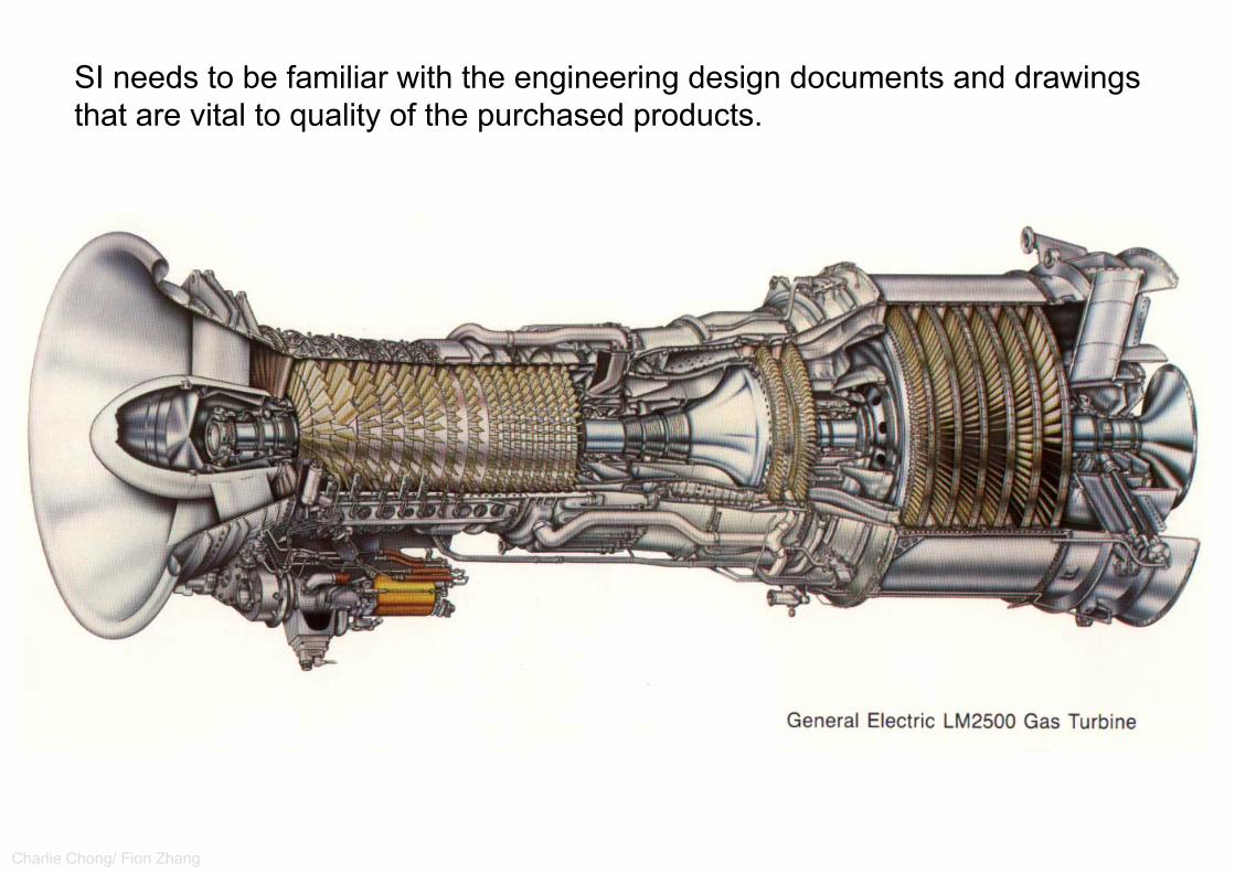
Charlie Chong/ Fion Zhang
SI needs to be familiar with the engineering design documents and drawings that are vital to quality of the purchased products.

Charlie Chong/ Fion Zhang
SI needs to be familiar with the engineering design documents and drawings that are vital to quality of the purchased products.
http://www.nasa.gov/images/content/2658main_COL_orbiter_wing_hi1.jpg

Charlie Chong/ Fion Zhang

Charlie Chong/ Fion Zhang

Charlie Chong/ Fion Zhang
8.2.4 Company and Client Standards The SI needs to be familiar with all company and client standards that are specified in the contractual agreements. These standards typically augment or supplement industry standards for issues not sufficiently well covered in industry standards. All mandatory requirements i.e. “shall/must” statements, included in the company specifications must be met or become an issue for an NCR and handled in accordance with standard purchaser management NCR systems requirements. Other issues contained in the specified standards such as those suggested or recommended i.e. “should” statements which are expectations of the S/V, but not necessarily requirements may become an issue to be reported in Supplier Observation Reports (SOR’s) and handled in accordance with standard purchaser management systems. Company and client standards may cover engineered and non-engineered equipment.
Comments:■ Shall/must - NCR■ Should - SOR
Charlie Chong/ Fion Zhang
8.2.5 Industry Codes and Standards 8.2.5.1 General The SI needs to be familiar with all industry codes and standards that are specified in the contractual agreements to the extent that requirements and expectations in those codes and standards are part of the contractual agreements and therefore part of the source inspector duties. Those industry codes and standards are typically published by recognized industry standards development organizations (SDO’s), such as those in the following subsections.

Charlie Chong/ Fion Zhang
8.2.5.2 API Standards There are a wide variety of API Standards that may be included in the contractual agreements to specify and control the quality of products for the petroleum, gas, petrochemical, chemical process and energy industries. A few of those that the SI should be familiar with and apply when specified are shown in the following subsections; but this list is not all inclusive. Others that are specified in the contractual agreements may be equally important to the quality of the delivered product. The information contained in the following industry standards is generic to a wide variety of products and therefore should be general knowledge to the experienced SI.

Charlie Chong/ Fion Zhang
API Std 610 Centrifugal Pumps for Petroleum, Petrochemical and Natural Gas Industries API 610 specifies requirements for centrifugal pumps, including pumps running in reverse as hydraulic power recovery turbines, for use in petroleum, petrochemical, and gas industry process services. This Standard is applicable to overhung pumps, between bearing pumps, and vertically suspended pumps. Clause 9 provides requirements applicable to specific types of pumps. All other clauses of this International Standard apply to all pump types. Illustrations are provided of the various specific pump types and the designations assigned to each specific pump type. It does not cover sealless pumps. This edition of API 610 is the adoption of ISO 13709:2009, Centrifugal Pumps for Petroleum, Petrochemical and Natural Gas Industries. NOTE: For sealless pumps, reference can be made to API Std 685. For heavy duty pumpapplications in industries other than petroleum, petrochemical and gas processing, reference can be made to ISO 9905. Relevant industry experience suggests pumps produced to this lnternationalStandard are cost effective when pumping liquids at conditions exceeding any one of the following:

Charlie Chong/ Fion Zhang
Relevant industry experience suggests pumps produced to this lnternationalStandard are cost effective when pumping liquids at conditions exceeding any one of the following:

API Std 610 Centrifugal Pumps for Petroleum, Petrochemical and Natural Gas Industries
Charlie Chong/ Fion Zhang

Charlie Chong/ Fion Zhang
Sealless PumpWhat is a sealless pump, exactly? What differentiates them from traditional sealed pumps? We've put together this informative resource to help you understand these advanced fluid handling technologies...
A sealless pump is essentially a conventional centrifugal pump without packed glands or mechanical seals. The dynamic seal that would normally be used to seal the impeller shaft is instead replaced by a static containment shell -- or shroud -- to form a completely sealed liquid end or pressure boundary.
Prime mover energy is transmitted to the sealed liquid end by a bank of external magnets, which pass force through the containment shell to the impeller shaft.
http://www.sundyne.com/Products/Pumps/Legacy-Brands/HMD-Kontro/Sealless-Magnetic-Drive-Pump-Facts

Charlie Chong/ Fion Zhang
Mechanical seals are designed to maintain their sealing capability by leaking small amounts of fluid as a means to keep the seal faces lubricated. This leakage then reaches the environment as either a liquid or vapor via a process referred to as fugitive emission. This represents the primary operational advantage of sealless pumps over sealed designs: sealless pumps dont leak, meaning that they can help reduce process inefficiencies,maximize output and minimize the risks posed to your process environment by hazardous and volatile materials.
Furthermore, seals, like bearings, must wear. As they wear, the seal faces lose their effectiveness and liquid loss through the seal increases. These fugitive emissions can get costly, resulting in lost time and money, as well as decreased worksite safety.
Without these seals -- which will ultimately fail, requiring expensive maintenance -- our Sundyne HMD Kontro sealless magnetic drive pumps represent a cost-effective and highly reliable alternative to traditional sealed pump designs.
http://www.sundyne.com/Products/Pumps/Legacy-Brands/HMD-Kontro/Sealless-Magnetic-Drive-Pump-Facts

Charlie Chong/ Fion Zhang
Environmental controls, occupational safety and product liability are now of paramount important to process plant operators. To this end, most companies will probably have a seal maintenance or support program in place to decrease their continuous leak problems. This involves large amounts of time and expense, as well as an extensive spares inventory. However, the most significant cost associated with the use of traditional sealed pumps is the downtime required when it comes time to replace failed seals.
By eliminating leakage and removing unreliable seals from the design, Sundyne HMD Kontrol sealless magnetic drive pumps provide immediate cost, safety and reliability advantages over traditional sealed designs.
http://www.sundyne.com/Products/Pumps/Legacy-Brands/HMD-Kontro/Sealless-Magnetic-Drive-Pump-Facts

Charlie Chong/ Fion Zhang http://news.thomasnet.com/fullstory/Sealless-Pump-suits-crucial-liquid-containment-applications-546887
Magnetic Driven Sealless Pumps
External Magnetic
Internal Magnetic

Charlie Chong/ Fion Zhang
API Std 611 General-Purpose Steam Turbines for Petroleum, Chemical, and Gas Industry Services API Std 611 specifies the minimum requirements for general-purpose steam turbines, including basic design, materials, related lubrication systems, controls, auxiliary systems and accessories. General-purpose turbines are horizontal or vertical turbines used to drive equipment that is usually spared, is relative small is size (power), or is in non-critical service. They are generally used where steam conditions will not exceed a pressure of 700 psig (48 bar) and a temperature of 750⁰F (400⁰C) or where speed will not exceed 6,000 rpm.
Specifications:< 700 psig (48 bar) < 750⁰F (400⁰C)

Charlie Chong/ Fion Zhang
API Std 611 General-Purpose Steam Turbines for Petroleum, Chemical, and Gas Industry Services
http://www.elliott-turbo.com/Files/Admin/Literature/GS%20Literature%20Uploaded%203-2015/svs.4022.1214---remanufactured-elliott-yr-steam-turbines.pdf

Charlie Chong/ Fion Zhang
API Std 611 General-Purpose Steam Turbines for Petroleum, Chemical, and Gas Industry Services
http://www.elliott-turbo.com/Files/Admin/Literature/GS%20Literature%20Uploaded%203-2015/svs.4022.1214---remanufactured-elliott-yr-steam-turbines.pdf

Charlie Chong/ Fion Zhang
API Std 611 General-Purpose Steam Turbines for Petroleum, Chemical, and Gas Industry Services
http://kesselsturbine.blogspot.com/

Charlie Chong/ Fion Zhang
API Std 611 General-Purpose Steam Turbines for Petroleum, Chemical, and Gas Industry Services
http://turbofluid.co.za/images/PDF/new/YR%20Turbines.pdf

Charlie Chong/ Fion Zhang http://turbofluid.co.za/images/PDF/new/YR%20Turbines.pdf

Charlie Chong/ Fion Zhang
API Std 614 Lubrication, Shaft-Sealing and Oil-Control Systems and Auxiliaries for Petroleum, Chemical and Gas Industry Services API Std 614 specifies the general requirements for lubrication systems, oil type shaft-sealing systems, dry-gas face-type shaft-sealing systems and control-oil systems for general-or special-purpose applications for equipment such as compressors, gears pumps and drivers. General purpose applications are limited to lubrication systems. This edition of API 614 is the adaptation of ISO 10438:2007, Petroleum, petro-chemical and natural gas industries – Lubrication, shaft-sealing and oil-control systems and auxiliaries.

Charlie Chong/ Fion Zhang
API Std 617 Axial and Centrifugal Compressors and Expander-Compressors for Petroleum, Chemical and Gas Industry Services API Std 617 specifies the minimum requirements for axial compressors, single-shaft and integrally geared process centrifugal compressors and expander-compressors. This standard does not apply to fans or blowers that develop less than 5 psi rise above atmospheric pressure. This standard also does not apply to packaged, integrally-geared centrifugal plant and instrument air compressors. Hot gas expanders over 500oF are not covered in this standard. Equipment covered by this standard are designed and constructed for a minimum service life of 20 years and at least 5 years uninterrupted operation.

Charlie Chong/ Fion Zhang
Axial and Centrifugal Compressors and Expander-Compressors for Petroleum, Chemical and Gas Industry Services

Charlie Chong/ Fion Zhang
Axial and Centrifugal Compressors and Expander-Compressors for Petroleum, Chemical and Gas Industry Services

Charlie Chong/ Fion Zhang
API Std 618 Reciprocating Compressors for Petroleum, Chemical, and Gas Industry Services API Std 618 specifies the minimum requirements for reciprocatingcompressors and their drivers for handling process air or gas with either lubricated or non-lubricated cylinders. Compressors covered by this standard are low to moderate speed machines. Also included in this standard are related lubrication systems, controls, instrumentation, intercoolers, aftercoolers, pulsation suppression devices and other auxiliary systems. This standard does not cover integral gas engines, compressors with single acting trunk-type pistons that also serve as crossheads, and plant or instrument-air compressors that discharge at or below 125 psig.

Charlie Chong/ Fion Zhang
API Std 618 Reciprocating Compressors for Petroleum, Chemical, and Gas Industry Services

Charlie Chong/ Fion Zhang
API Std 618 Reciprocating Compressors for Petroleum, Chemical, and Gas Industry Services
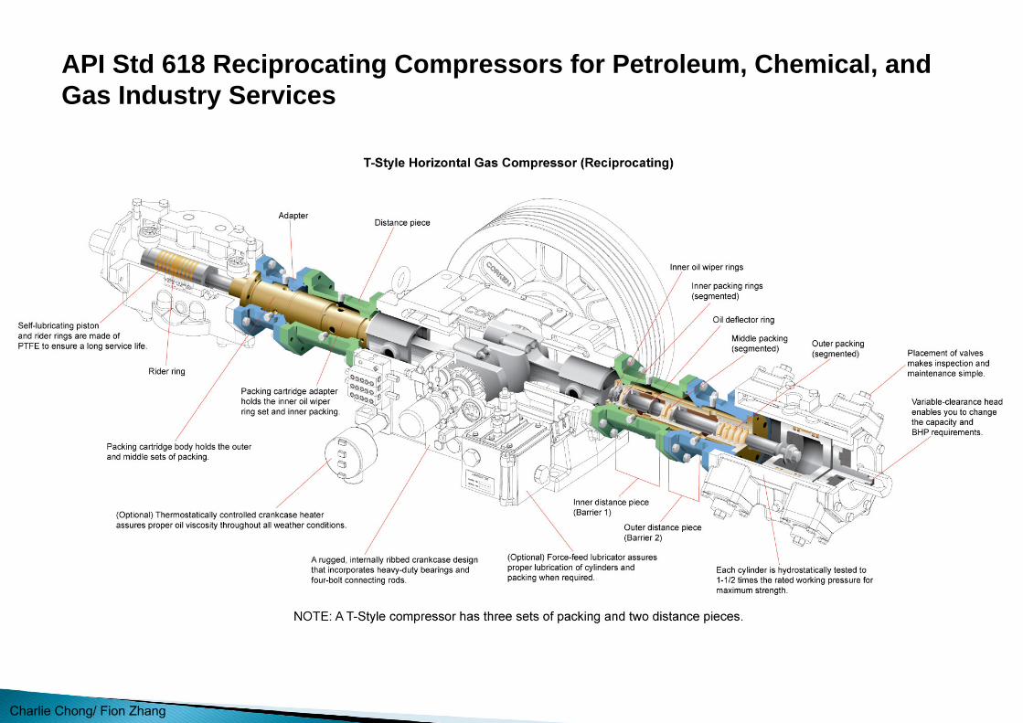
Charlie Chong/ Fion Zhang
API Std 618 Reciprocating Compressors for Petroleum, Chemical, and Gas Industry Services

Charlie Chong/ Fion Zhang

Charlie Chong/ Fion Zhang
API Std 677 General-Purpose Gear Units for Petroleum, Chemical and Gas Industry Services This standard covers the minimum requirements for general-purpose, enclosed single and multistage gear units incorporating parallel shaft helical and right angle spiral bevel gears for the petroleum, chemical, and gas industries. Gears manufactured according to this standard shall be limited to the following pitchline velocities. Helical gears should not exceed 60 m/s(12,000 ft/min), and spiral bevels shall not exceed 40 m/s (8,000 ft/min). Spiral bevel gearsets shall be considered matched sets. This standard is not intended to apply to gears in special-purpose service, which are covered in API Std 613; to gears integral with other equipment; to epicyclic gear assemblies; or gears with non-involute tooth forms.

Charlie Chong/ Fion Zhang
API Std 682 Pumps-Shaft Sealing Systems for Centrifugal and Rotary Pumps This Standard specifies requirements and gives recommendations for sealing systems for centrifugal and rotary pumps used in the petroleum, natural gas and chemical industries. It is applicable mainly for hazardous, flammable and/or toxic services where a greater degree of reliability is required for the improvement of equipment availability and the reduction of both emissions to the atmosphere and life-cycle sealing costs. It covers seals for pump shaft diameters from 20 mm (0,75 in) to 110 mm (4,3 in).

Charlie Chong/ Fion Zhang
API Std 682 Shaft Sealing Systems for Centrifugal and Rotary Pumps API Std 682 specifies requirements and gives recommendations for sealing systems for centrifugal and rotary pumps used in the petroleum, natural gas and chemical industries. It is applicable mainly for hazardous, flammable and/or toxic services where a greater degree of reliability is required for the improvement of equipment availability and the reduction of both emissions to the atmosphere and life-cycle sealing costs. It covers seals for pump shaft diameters from 20 mm (0,75 in) to 110 mm (4,3 in).

Charlie Chong/ Fion Zhang
Rotary Pumps

Charlie Chong/ Fion Zhang
Rotary Pumps

Charlie Chong/ Fion Zhang
Rotary Pumps

Charlie Chong/ Fion Zhang
Hydraulic Institute StandardsHI 14.6 Rotodynamic Pumps for Hydraulic Performance Acceptance Tests This Standard is for centrifugal, sealless centrifugal and regenerative turbine pumps of all industrial types except vertical multistage diffuser type. It includes detailed procedures on the setup and conduct of hydrostatic and performance tests of such pumps.

Charlie Chong/ Fion Zhang
HMD Sealless Pumps are magnetically driven, they have no mechanical seals, and only a single, fully trapped gasket that ensures system integrity, even at high temperatures and pressures.

Charlie Chong/ Fion Zhang
Sealless Pump
http://ansimag.com/Products/Model-Locator/GSA-GSI-Frame-1

Charlie Chong/ Fion Zhang
Sealless Pump
http://ansimag.com/Products/Model-Locator/GSA-GSI-Frame-1
External Magnetic
Internal Magnetic

Charlie Chong/ Fion Zhang http://ansimag.com/Products/Model-Locator/GSA-GSI-Frame-1

Charlie Chong/ Fion Zhang
Sealless Pump
http://www.process-controls.com/Vissers_Sales/Magnatex_Mag_Drive_Pumps_MAXP.htm

Charlie Chong/ Fion Zhang
8.2.5.3 ASME Codes and Standards There are a wide variety of ASME Codes and Standards that may be included in the contractual agreements to specify equipment fabrication methods and control the quality of products for the energy industry. A few of those that the SI should be familiar with and apply when specified are shown in the following subsections; but this list is not all inclusive. Occasionally there may be other sections of the ASME BPVC that will be specified on different projects in which the SI will be involved.

Charlie Chong/ Fion Zhang
ASME BPVC Section II—Materials This section of the BPVC is divided into four parts covering materials for the construction of piping and pressure vessels.

Charlie Chong/ Fion Zhang
Part A —Ferrous Material Specifications This part contains the individual specifications for ferrous materials that are allowed in the construction of pressure vessels and piping designed to the ASME BPVC. Part A covers all forms of ferrous material products like wrought, castings, forgings, plates, piping valves, bolting, etc. The criteria addressed by each ferrous material specification vary based on the characteristics of the material and final use for which it is intended. Some examples of issues covered include: ordering information, heat treatment, chemical composition, mechanical properties, tests and examinations, dimensions and tolerances and the steel making practice. The source inspector should be familiar with the contents of whichever materials are specified in the contractual agreements. The specification covered in ASME BPVC Section II, Part A that the SI needs to be familiar with for purposes of the examination is:
■ SA-370, Test Methods and Definitions of Mechanical Testing Steel Products.

Charlie Chong/ Fion Zhang
SA-370Test Methods and Definitions of Mechanical Testing Steel Products.

Charlie Chong/ Fion Zhang
Part B —Nonferrous Material Specifications This part contains the individual specifications for nonferrous materials that are allowed in the construction of pressure vessels and piping designed to the ASME BPVC. Part B covers all forms of nonferrous material products like wrought, castings, forgings, plates, piping valves, bolting, etc. allowed for in the construction of ASME BPVC equipment. The types of nonferrous material alloys included in Part B are: aluminum, copper, nickel, titanium, and zirconium. The criteria addressed by each nonferrous material specification vary based on the characteristics of the material and final use for which it is intended. Some examples of issues covered include: ordering information, heat treatment, chemical composition, mechanical properties, tests and examinations, dimensions and tolerances and the melting practice. The source inspector should be familiar with the contents of whichever materials are specified in the contractual agreements.

Charlie Chong/ Fion Zhang
Part C —Specifications for Welding Rods, Electrodes and Filler Metals Part C covers material specifications for the manufacture, acceptability, chemical composition, mechanical usability, surfacing, testing, operating characteristics and intended uses of welding rods, electrodes and filler materials. The material specifications are designated by SFA numbers derived from AWS specifications. The source inspector would typically reference these specifications for whichever welding materials are specified in the contractual agreements to ensure that the right materials are being used in fabrication.
Part D —Materials Properties Part D provides tables for design stress values, tensile strength, yield strength, and other important chemical and physical properties for all the material specifications contained in Parts A and B. This section is primarily intended for designers of ASME BPVC equipment.

Charlie Chong/ Fion Zhang

Charlie Chong/ Fion Zhang
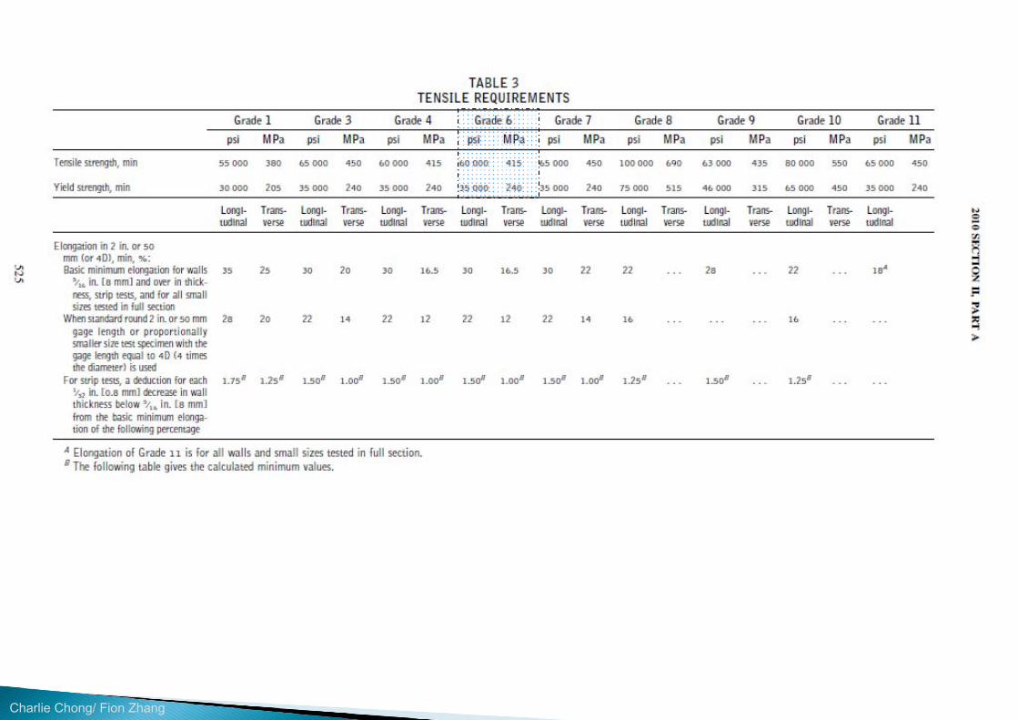
Charlie Chong/ Fion Zhang
Charlie Chong/ Fion Zhang

Charlie Chong/ Fion Zhang

Charlie Chong/ Fion Zhang

Charlie Chong/ Fion Zhang

Charlie Chong/ Fion Zhang
ASME BPVC Section V—Nondestructive Examination This section of the BPVC contains requirements and methods for NDE techniques that are specified by other sections of the ASME BPVC and/or contractual agreements. Most of the common methods of NDE are covered in Section V including RT, UT, MT, PT, VT, and LT. Appendix A of Section V presents a listing of common imperfections and damage mechanisms and the NDE methods that are generally capable of detecting them. Section V also provides guidance on methods of evaluating NDE results (?) . The source inspector should be thoroughly familiar with the contents of Section V for whichever NDE method is specified in contractual agreements and/or ITP. For the purposes of SI examination, some of the content covered in ASME BPVC Section V that applicants should focus on includes:

Charlie Chong/ Fion Zhang
All definitions in Subsection A, Article 1, Appendix I and Subsection B, Article 30, SE-1316.
Article 1 on General Requirements for NDE. Article 2 on Radiographic Examination. Article 4 on Ultrasonic Examination Methods of Welds. Article 5 on Ultrasonic Examination Methods for Materials. Article 6 on Liquid Penetrant Examination. Article 7 on Magnetic Particle Examination. Article 9 on Visual Examination. Article 10 on Leak Testing. Article 23, Section 797 on UT Thickness Testing.

Charlie Chong/ Fion Zhang
ASME Section VIII Division 1 Boiler Pressure Vessel CodeUCS-56-57 Appendix 7 - Examination of Steel Casting
ASME BPVC Section IX—Qualification Standard for Welding and Brazing Procedures, Welders, Brazers, and Welding and Brazing Operators Section IX of the ASME BPVC Part QW covers the qualifications of welders, welding operators and the procedures that will be employed during fabrication. The primary subjects covered include: welding general requirements, welding procedure specifications and qualification, and welder performance qualification. Section IX does not cover acceptance criteria for production welds. Section IX also covers fabrication by brazing (Part QB), so the SI inspector should be aware of that section, but will not need to be familiar with it until and unless assigned to a project that specifies brazed construction. The source inspector should be thoroughly familiar with the contents of Section IX Part QW with regard to the WPS, PQR and WPQ that are specified in contractual agreements and/or ITP. For the purposes of SI examination the applicants need to focus their attention on the following sections of ASME BPVC Section IX:

Charlie Chong/ Fion Zhang
Welding General Requirements QW 100 to 190. Welding Procedure Qualifications QW 200 to 290. Welding Performance Qualifications QW 300 to 380. Welding Data QW 400 to 490. Standard Welding Procedure Specifications QW 500 to 540.
Charlie Chong/ Fion Zhang
8.2.5.4 ASNT StandardsASNT SNT-TC-1A This recommended practice establishes a general framework for a qualification and certification program for NDE technicians. In addition the standard provides recommended educational requirements and training requirements for different test methods. The SI should be thoroughly familiar with this standard, including the duties and responsibilities for each of the 3 levels of NDE qualified technician.

Charlie Chong/ Fion Zhang
SSPC StandardsSSPC-PA 2 Coating Applications Standard No. 2, Procedure for Determining Conformance to Dry Coating Thickness Requirements This standard describes a procedure for determining conformance to a specified dry film thickness (DFT) range on metal substrates using NDE thickness gauges. The SI inspector should be familiar with Sections 1 to 8 of this standard.
SSPC Surface Preparation Guide This guideline briefly describes the scope of the 7 different SSPC and NACE Surface Preparation Standards with application to source inspection. The source inspector should be familiar with the scope of the 7 standards listed below that are included in this guide, but need not be familiar with the details in the specific standards for examination purposes.

Charlie Chong/ Fion Zhang
SSPC-SP1—Solvent Cleaning. SSPC-SP3—Power Tool Cleaning. SSPC-SP5 or NACE 1—White Metal Blast Cleaning. SSPC-SP6 or NACE 3—Commercial Blast Cleaning. SSPC-SP7 or NACE 4—Brush-Off Blast Cleaning. SSPC-SP10 or NACE 2—Near-White Blast Cleaning. SSPC-SP11—Power Tool Cleaning to Bare Metal.
1/3/5/6/7/10/11

Charlie Chong/ Fion Zhang
8.2.6 Welding Procedures and Qualifications Welding procedure qualifications are the responsibility of the S/V while it is the responsibility of the source inspector that they be verified as the ones approved by the purchaser. Prior to performing welding inspection, the SI should confirm that the version of the WPS in hand has been reviewed and approved by the responsible person e.g. engineer/WPS/PQR SME. ASME BPVC Section IX, is the appropriate references for knowledge andunderstanding of WPS/PQR’s.
8.2.7 NDE Procedures Development of NDE procedures are the responsibility of the S/V while it is the responsibility of the source inspector that they be verified as the ones approved for use. Prior to witnessing NDE, the SI should confirm that the version of the NDE procedure in hand has been reviewed and approved by the responsible person e.g. engineer/NDE SME. The AWS Welding Inspection Handbook, ASME BPVC Section V, AWS D1.1 and ASNT SNT-TC-1A are the appropriate references for knowledge and understanding of NDE procedures and required training and certification of NDE technicians.

Charlie Chong/ Fion Zhang
SME- Subject Matter Expert我们的大学,其实应该聘请这些能干的退休教授. 或许在职的砖头怕被排斥.http://cn.bing.com/videos/search?q=Walter+Lewin&FORM=HDRSC3https://www.youtube.com/channel/UCiEHVhv0SBMpP75JbzJShqw

Charlie Chong/ Fion Zhang
8.2.8 Project Schedules While the responsibility of establishing and monitoring the delivery is not generally in the purview of the SI and the responsibility of meeting the schedule remains with the S/V, the SI may be requested to report on fabrication status or slippage of mile-stone progress. The SI should notify the inspection coordinator if he/she believes that product quality may be compromised by schedule pressures.

Charlie Chong/ Fion Zhang
8.3 Performing the Source Inspection 8.3.1 Individuals assigned to perform the source inspection activity must follow the ITP as specified by the purchaser. Visual inspection, welding inspection, dimensional inspections, observing NDE, and all other examinations and tests must be performed in accordance with the source ITP, project specification and applicable code and standards and meet the applicable acceptance criteria. See Section 9 for Examination Methods, Tools and Equipment. 8.3.2 One important step in the source inspection work process is to verify evidence that the S/V personnel conducting the fabrication and quality control steps during fabrication are properly trained, qualified and certified, as specified in the ITP or other contractual documents. This may include verification of such credentials as: S/V quality personnel qualifications per the specified standards, checking welder log books, and NDE technician certifications per the specified standards, such as ASNT SNT TC-1A, EPRI, or API Industry Qualified Examiners.

Charlie Chong/ Fion Zhang
8.3.3 During the course of manufacturing and fabrication, the S/V may propose contract deviations that could impact cost, schedule and/or quality. In such cases, the source inspector should request that the S/V propose such changes in writing for review and approval by the purchaser and/or owner-user of the equipment.

Charlie Chong/ Fion Zhang
8.4 Source Inspection Work Process Scheduled Planning Events 8.4.1 General Typical source inspection scheduled work process events include the following: 8.4.2 Pre-purchase Meeting (Prior to Contract Placement) The source inspector may or may not participate in a pre-purchase meeting. The purpose of such a meeting is to cover some specific design, fabrication, and/or QA/QC requirements expected of the S/V to make sure that their bid does not in-advertently overlook them and result in unanticipated surprises during fabrication and source inspection activities.

Charlie Chong/ Fion Zhang
8.4.3 Pre-inspection Meeting (Prior to Start of Manufacturing) The source inspector assigned to the S/V facility should participate in the pre-inspection meeting (PIM). The purpose of this meeting is to ensure that everyone at the S/V who will be involved in manufacturing, fabrication and monitoring the quality of the equipment fully understands specific requirements and details of the job, especially those requirements that may be non-routine or different relative to normal S/V quality surveillance. Advance preparation by the source inspector is important for the pre-inspection meeting to ensure the meeting covers all necessary issues requirements as specified in the contractual agreements and source inspector’s company policy/practices. Those requirements may include review of:

Charlie Chong/ Fion Zhang
PO and contractual agreements. Engineering, technical and material requirements and status. Fabrication schedules. Critical path and long-lead equipment/materials. Quality requirements e.g. ITP, NCR, inspection frequency, etc. Sub-suppliers and their quality requirements. Special requirements e.g. performance or functional testing requirements. Painting, preservation and tagging. Communication requirements e.g. inspection point notification, report
distribution, proposed changes, hold points, schedule impacts, etc. Shipping and release plan. Final documentation requirements. Recording and reporting any observations, exceptions or deviations.
These source inspection work process events may also be observed or handled by others besides the source inspector including: project engineering,client representatives or third party inspection agency.

Charlie Chong/ Fion Zhang
8.5 Report Writing 8.5.1 A key deliverable of source inspection is the progressive inspection reports detailing the documents reviewed, inspection activity performed, observed and/or witnessed during the source inspection visits. The report is normally on a standard format, and follows a consistent approach to reporting as specified by the purchaser.
8.5.2 The source inspector should reference the following minimum information in each report: Date of visit. Appropriate contract number and key information. Purpose of visit. Action items or areas of concerns. Results of inspection/surveillance. Reference drawings/data used (including drawing numbers) to perform
inspection/surveillance. Revisions of referenced drawings/data. Reference to the applicable requirement in the ITP. Identification of nonconforming or deviating items/issues.

Charlie Chong/ Fion Zhang
8.5.3 Photographs are frequently used in the inspection reports as they assist in the description of the inspection results. The SI should request permission from the S/V prior to taking any photographs. Care should be exercised to ensure that an appropriate number of photos are attached as too many can be detrimental to report issuance due to file size. Photos should be dated and labeled with description of area of interest or product tag reference so that they can be easily understood by those reading the SI reports. 8.5.4 Reports should be submitted to the inspection coordinator for review of content and technical clarity before they are distributed to the purchaser unless otherwise instructed.

Charlie Chong/ Fion Zhang
8.6 Nonconformance/Deviations 8.6.1 When deviations to the contractual agreement or its referenced specifications, drawings, codes or standards are identified, the source inspector should identify them as nonconformances. The source inspector should notify the inspection coordinator as soon as practical once a nonconformance has been identified. 8.6.2 Nonconformance reports should reference the following minimum
information: Date of inspection. Contract number and information. Description of nonconforming item and issue. Photo of discrepancy if possible. Specifications, drawings, codes or standards involved. Impact on the product. S/V recommended disposition of the nonconformance.

Charlie Chong/ Fion Zhang
8.6.3 The source inspector should issue the nonconformance report to the inspection coordinator for review and distribution unless instructed otherwise. 8.6.4 In general, deviations from specifications must be approved by the responsible engineer/technical personnel. 8.6.5 Acceptable disposition of a nonconformance (as approved by the responsible engineer/ technicial personnel) may include: Use as is. Rework/repair per original contractual documents or approved repair
procedure. Scrap the equipment/component involved and start over.
8.6.6 Once the disposition of the nonconformance has been agreed by all appropriate parties and implemented, the source inspector is normally responsible for determining if the nonconforming item currently conforms to the original or revised requirements based on the agreed disposition. It is SI responsibility to verify that NCR disposition has been properly implemented.
Comment: NCR close-out, SI Responsibility ≠ S/V
Charlie Chong/ Fion Zhang
8.7 Source Inspection Project Continuous Improvement At the completion of the source inspection activities at an S/V, the source inspector, inspection coordinator, and all others involved in the “planning and doing” processes should review the entire planning and implementations part of the “Plan–Do–Check–Act” continuous improvement (CI) cycle to determine which activities went well and where improvements/ adjustments could/should be made. Determinations should be made if improvements are possible and necessary in the source inspection management systems; the source inspection project planning process: the creation and implementation of the ITP; and the implementation of the source inspection work process events. Any such improvements should be documented and made available to source inspection managers and coordinators to implement the improvements. This should include an evaluation of the performance of the S/V.

Charlie Chong/ Fion Zhang
8.8 Source Inspector Continuous Improvement The source inspector can/should also learn from the continuous improvement cycle how he/she can improve their performance on the job by answering such questions as: Are there some industry codes and standards that I should be more
familiar with? Are there any safety and or personal conduct improvements I can make? Can I improve the way I write the various SI reports? Do I need to improve my review of project documents before showing up
at the S/V site? Can I improve the way I conducted the pre-fabrication meeting? Can I improve the timeliness of closing out my part of the source
inspection project?

Charlie Chong/ Fion Zhang
tank erections whereby

Charlie Chong/ Fion Zhang
tank erections whereby

Charlie Chong/ Fion Zhang
9.0 Examination Methods, Tools and Equipment 9.1 General This section describes the typical examination methods, tools and equipment with which source inspectors should be familiar during the course of their surveillance at an S/V. Requirements for examinations from the purchaser or references in the contract agreement that may be more stringent than industry codes/standards or the S/V normal procedures should be included in the ITP.
Charlie Chong/ Fion Zhang
9.2 Review and Confirmation of Materials of Construction 9.2.1 Ensuring that the S/V is using the correct material during the
manufacturing of the equipment is a critical element of quality surveillance. Typical reviews should consist of the following:
1. Material Test Reports (MTRs)—The information necessary for the source inspector to know and understand about MTRs is covered in ASME BPVC Section II, SA-370, and EN10204.
2. Any reports e.g. MTRs that have been modified, corrected, or altered should be cause for further investigation as these could indicate the potential for the material or component being counterfeit material. All MTR’s must be legible.
3. Confirming that the construction materials proposed are the actual materials used during construction is a typical source inspection activity. The source inspector should:

Charlie Chong/ Fion Zhang
Confirm the correct material type and grade. Confirm the origin of the material. Check material size and/or thickness. Verify traceability of the material to a certifying document. Verify that the material complies with specific chemical and/or
mechanical properties as specified in the contractual documents. Verify compliance to NACE MR0175/ISO 15156 for equipment in sour
service. Heat treat and hardness to be verified. Maximum hardness requirements for P-Numbered alloy steels are given in NACE MR0103, Table 2. Other alloy steels shall have a maximum hardness of 22 HRC (237 HBW) (NACE MR0103, 2.1.6. Ferrous materials not covered by NACE MR 0103-2007 or NACE MR 0175-2008 shall have a maximum yield strength of 620 N/mm2 (90,000 psi) and a maximum Rockwell hardness of HRC 22.

Charlie Chong/ Fion Zhang
Check for evidence of specified heat treatment. This is typically done by verifying that material grade, type and serial
number match the material certifying document. Some S/V’s quality programs as well as purchasers’ have various methods for ensuring that the correct material is used in manufacturing with the use of positive material identification (PMI). The source inspector should be familiar with those methods and ensure compliance. API RP 578 is a good reference document for material verification and positive material identification.
Note:PMI- API578

Charlie Chong/ Fion Zhang
API578 PMI

Charlie Chong/ Fion Zhang
API578 PMI

Charlie Chong/ Fion Zhang
NACE Store - MR0103-2012, Materials Resistant to Sulfide Stress Cracking in Corrosive Petroleum Refining Environments
OverviewDefines material requirements for resistance to sulfide stress cracking (SSC) in sour refinery process environments (i.e., environments that contain wet hydrogen sulfide [H2S]). The term "wet H2S cracking" as used in the refining industry covers a range of damage mechanisms that can occur due to the effects of hydrogen charging in wet H2S refinery or gas plant process environments. One of the types of material damage that can occur as a result of hydrogen charging is sulfide stress cracking (SSC) of hard weldments and microstructures, which is addressed by this standard. This standard is intended to be utilized by refineries, equipment manufacturers, engineering contractors, and construction contractors.

Charlie Chong/ Fion Zhang
NACE Store - ANSI/NACE MR0175/ISO 15156 2015 EDITIONPetroleum and natural gas industries Materials for use in H2S-containing environments in oil and gas production
OverviewNACE MR0175/ISO 15156 gives requirements and recommendations for the selection and qualification of carbon and low-alloy steels, corrosion-resistant alloys, and other alloys for service in equipment used in oil and natural gas production and natural gas treatment plants in H2S-containing environments, whose failure could pose a risk to the health and safety of the public and personnel or to the equipment itself.

Charlie Chong/ Fion Zhang
9.2.2 The SI should be aware of the potential for counterfeit materials/ documents slipping into the supply chain. Key issues to watch for include, but are not limited to: Generic documentation which is not product specific. Material or equipment containing minimal or no documentation. Markings or logos that are questionable or obliterated 废除. Items that have inconsistent appearance. Documents that have been altered. Items that lack material traceability or product certification. ASME or ASTM stampings that may have been counterfeited.

Charlie Chong/ Fion Zhang
9.3 Dimensional Inspections 9.3.1 The SI should be proficient in understanding and performing dimensional inspections. Equipment such as tape measures, dial indicators, calipers, micro-meters, protractors, vibration gages, temperature gages, pressure gages, levels are all typical tools that are used for dimensional inspection. The SI should be familiar with proper usage and application of the these tools along with calibration requirements. Tools used for precision measurement are typically calibrated in accordance with a S/V’s written calibration procedure in accordance with NIST, ISO Guide 99 and other industry standards for calibration. Calibration is a comparison between measurements, one of a known magnitude or correctness (the standard) compared to the measuring device under test in order to establish the accuracy of a measuring device. The main objective for performing calibration, it checks or verifies the accuracy and determines the traceability of the instrument.
ISO/IEC-GUIDE 99 › International vocabulary of metrology - Basic and general concepts and associated terms (VIM)ISO/IEC-GUIDE 99 - 1ST EDITION

Charlie Chong/ Fion Zhang
The accuracy of a measuring device can become suspect for various reasons.Some of the common causes of the loss of accuracy are: Normal wear during usage. Misuse of the instrument either in application or mishandling (i.e. dropping,
incorrect storage etc.). Environmental issues such as extreme temperature changes, hazardous
or corrosive conditions.

Charlie Chong/ Fion Zhang
Total Station

Charlie Chong/ Fion Zhang
The S/V should have a calibration procedure that as a minimum addresses: the calibration intervals, ■ calibration tolerances, control of masters, ■ traceability requirements, care of the instrument, ■ records, and recalibration.
Most companies establish a calibration interval based on multiple variables, including manufacturer’s recommendations, amount and type of usage, conditions of the unit, accuracy requirements, and established history of previous calibrations. Obviously the shorter the interval or more frequent the calibration the lower the risk concerning use of a device that does not comply with the calibration requirements and potential for unacceptable material to beinadvertently accepted. However calibration can be an expensive process, with potential serious ramifications 后果 for acceptance of product later found to be non-conforming. Therefore the S/V is required to take all potential parameters in consideration when establishing a calibration interval. S/V’s that do not perform a lot of detailed precision measurement may elect to establish a calibration requirement for the measurement device to be calibrated prior to each use.

Charlie Chong/ Fion Zhang
The S/V should maintain adequate records addressing the method of controlling precision measuring devices that require calibration. The records should include, storage and handling requirements, calibration due dates, prevention of usage of devices past calibration due date, means to identify product verified using a specific measuring device, and determine optimal calibration interval based on an established history. Maintaining accurate calibration records will also provide the S/V with an indicator of a measuring device reaching the end of its lifetime in relation to ability to hold calibration or extent of re-calibration required each time it is subjected to calibration.

Charlie Chong/ Fion Zhang
9.3.2 The S/V should include in the calibration procedure a method to recall material checked with a device that was later found to not be in calibration. Finding of a device that fails calibration at the established calibration interval will normally require the issuance of a non-conformance in the S/V’s quality system. When a device is found to be out of calibration, any measurements made since the last known calibration is suspect. The S/V must determine as part of the non-conformance resolution the extent of the calibration error, the criticality of product verified with the device, and ability to identify all potentially unacceptable product either in house or shipped. Depending on the level of error and criticality of the product the S/V may be able to re-measure or rework product still in house. The S/V may also need to contact customers that have received product to issue a recall or advise of the need for service to bring the product into specification requirements.

Charlie Chong/ Fion Zhang
9.3.3 When performing dimensional inspections, the source inspector should be familiar with the dimensional requirements and the allowable tolerances. Actual dimensions should be recorded in the inspection reference drawing. Dimensions which exceed the tolerances should be reported as a nonconformance or deviation.

Charlie Chong/ Fion Zhang
9.4 Visual Inspections 9.4.1 Adequate lighting is essential when performing visual inspection. The SI must be familiar with the minimum lighting requirements defined by the applicable code, standard or specification. If there is inadequate lighting available during the visual inspection which is not uncommon in some shops, the source inspector must address these concerns with the S/V and inspection coordinator to resolve. Portable lighting such as pen lights, high power flashlights, etc. are common tools that the source inspector may need with him/her in order to perform adequate visual inspection. 9.4.2 Source Inspectors who are performing visual inspections of welding, coatings, etc. should be appropriately trained, qualified and/or certified as required to perform those activities in accordance with the applicable codes or standards including the visual acuity requirements.

Charlie Chong/ Fion Zhang
9.5 Nondestructive Examination (NDE) Techniques 9.5.1 General9.5.1.1 The primary source for the specific NDE techniques to be applied during M&F by the S/V is included in the applicable project specifications. Those documents should reference other appropriate codes/standards for NDE methods such as ASME BPVC Section V & NDE technician qualifications such as ASNT SNT TC-1A. The source inspector should be familiar with the NDE qualification/certification processes described in ASNT SNT TC-1A, especially what NDE duties/ responsibilities can be carried out by Levels I, II, and III NDE technicians.
9.5.1.2 The source inspector should be familiar with NDE terminology contained in ASME BPVC Section V, Subsection A, Article 1, Mandatory Appendix 1 and Subsection B, Article 30, SE-1316.

Charlie Chong/ Fion Zhang
9.5.2 Penetrant Testing (PT) ASME BPVC Section V, Article 6, T-620 cover most of what the source inspector needs to know about PT. Discontinuities revealed during PT are normally recorded on an NDE report.
9.5.3 Magnetic Particle Testing (MT) ASME BPVC Section V, Article 7, T-750 cover most of what the source inspector needs to know about MT. Discontinuities revealed during MT are normally recorded on an NDE report.
9.5.4 Radiographic Testing (RT) ASME BPVC Section V, Article 2, T-220 and E-94 or E1742 cover most of what the source inspector needs to know about RT. Discontinuities revealed during RT are normally recorded on an NDE report.

Charlie Chong/ Fion Zhang
9.5.5 Ultrasonic Testing (UT) ASME BPVC Section V, Article 4, and E 797 and Article 5, T-530 cover most of what the source inspector needs to know about UT. Discontinuities revealed during UT are normally recorded on an NDE report. 9.5.6 Positive Material Identification (PMI) API RP 578 covers most of what the source inspector needs to know about material verification and PMI.

Charlie Chong/ Fion Zhang
9.6 Destructive Testing 9.6.1 Destructive testing is defined as those tests that are performed on metals for the purposes of determining mechanical properties and which involve testing of sample coupons. Examples of such tests include tensile testing, bend testing and Charpy impact testing.
9.6.2 Tensile testing is performed to determine yield strength (point at which elastic deformation becomes plastic/permanent deformation) and ultimate tensile strength (fracture point) of an item.
9.6.3 Bend testing is commonly performed on weld coupons to check the (1) ductility and (2) integrity of welds.

Charlie Chong/ Fion Zhang
9.6.4 Charpy impact testing is performed to determine toughness of metals and welds. It may be specified for a variety of reasons at a variety of different temperatures to show that the vessel or piping system has the ability to deform plastically before failing i.e. avoid catastrophic brittle fracture. For many construction codes, impact testing often becomes a requirement below temperatures of –20°F (-19°C) , but the engineering specifications may require impact testing at other temperatures as well.
9.6.5 Most of the information necessary for the source inspector to know and understand about destructive testing of metals is covered in ASME Section IX.

Charlie Chong/ Fion Zhang
9.7 Pressure/Leak Testing 9.7.1 General Pressure/leak testing is normally specified by the applicable codes/standards and contractual agreements. 9.7.2 Pressure/Leak Testing 9.7.2.1 Hydrotesting is conducted with water for the integrity of the equipment and a gas test is performed as a leak test. As the name indicates, pressure testing involves testing with elevated pressures, often above that at which the component will normally operate, so safety is of utmost importance when witnessing a pressure test. Pressure tests must be conducted in accordance with the construction code or standard to which the item was built e.g. ASME BPVC Section VIII for vessels or ASME B31.3 for process piping. API standards like API 610 also address minimum requirement to hydrotest pump pressure containing parts before further testing like performance or running tests. These codes generally indicate how to witness such a test safely after the pressure has equalized and stabilized. Whether testing by hydrotest, hydro-pneumatic or pneumatic, the pressure testing equipment should have the means to prevent over pressuring the equipment under test.

Charlie Chong/ Fion Zhang
9.7.2.2 Hydrotesting is the most common method of pressure testing and involves the application of pressure using water. It’s very important that high point vents be opened during filling and before the application of pressure to ensure that there is no air left in the system. All connection welding to case should be completed prior to hydrotest. Verification that chloride content is less than 50ppm is to be conducted when hydrotesting austenitic stainless steels is a common requirement, the SI should be aware of this when austenitic stainless steel is tested. Verification of drying after hydrostatic testing is critical to prevent deposition of chlorides. S/V shop should have a safe area guarded by metal netting that would prevent pieces of metal from flying outside of the save compartment in case a tested part fails and disintegrates. The SI should verify a current lab analysis has been performed concerning the water quality in compliance with PO/Contractual requirements, including chloride content or other items as specified in these documents.

Charlie Chong/ Fion Zhang
9.7.2.3 Pneumatic Testing is generally conducted with air though sometimes it’s conducted with a combination of air and water. There are significantly greater risks involved in higher pressure pneumatic testing, so it should never be conducted without the full knowledge and consent of the responsible engineer who has been satisfied that the potential for brittle fracture during test is negligible. The danger lies in pieces of the equipment that fail under pneumatic pressure being propelled with great force for long distances and thereby doing a lot of damage and/or inflicting severe injury. API 682 has more detail around pneumatic testing. The SI should be familiar with this requirement as it’s a critical test.
Note:API682Pumps shaft sealing systems for centrifugal and rotary pumps third edition; ISO 21049 adoption

Charlie Chong/ Fion Zhang
9.7.2.4 Leak Testing is generally the term used to describe low pressuretesting with air or gas just to see if the joints in a piece of equipment e.g. flanges and threaded connections are leak tight after assembly. Leak tests are usually done at low pressures which are substantially below equipment design pressures to minimize risk of injury. Specialized leak tests with helium or other gases have to be specified by contractual documents which will detail the leak test procedure and generally reference an industry standard that must be followed.

Charlie Chong/ Fion Zhang
9.8 Performance/ Functional Testing/ Mechanical Run Test Performance and functional testing is typically required for all rotating equipment. Prior to performance or functional testing, the S/V should provide a detailed functional test procedure which has been submitted for review and comment from the purchaser. This functional/ performance test may also be attended by other interested parties in the project. Sufficient advance notice is necessary to ensure all interested parties are available and can attend this test. The SI should be very familiar with the functional/performance test procedures and a detailed report that is expected at the end. SI should also verify that all attributes of the test are accurately reported in the final test report, provided by the S/V.

Charlie Chong/ Fion Zhang
Following is an example of this functional testing, This could change based on customer requirements:Example: A performance curve is plotted to indicate the variation of pump differential head against volumetric flow (gpm) of a liquid at an indicated rotational speed or velocity, while consuming a specific quantity of horsepower (BHP). The performance curve typically consists of the following curves relating with each other on a common graph. These curves are: • The Head-Flow Curve. It is called the H-Q Curve. • The Efficiency Curve. • The Energy Curve. It records Brake Horsepower, BHP. • Net Positive Suction Head, NPSH curve.

Charlie Chong/ Fion Zhang
Difference Between Horsepower and Brake HorsepowerHorsepower vs Brake Horsepower Horsepower is a unit of measurement of power, which is the time rate of work being done. The term was coined by Scottish engineer James Watt in the late 18th century as a reference to the output of steam engines, but later expanded to include the output power of engines, as well as turbines, electric motors and other machinery.
More about HorsepowerThe unit of horsepower has many definitions and varies according to regions too; it is considered a vague unit.
The mechanical horsepower, also known as imperial horsepower is the 550 foot-pounds per second which is approximately the same as 745.7 Watts in SI units. The horsepower unit used for rating electric motors is equal to 746 watts. The horsepower unit used for rating steam boilers is known as the Boiler Horsepower and it is equivalent to equivalent to 34.5 pounds of water evaporated per hour at 212 degrees Fahrenheit, or 9,809.5 watts.
http://www.differencebetween.com/difference-between-horsepower-and-vs-brake-horsepower/

Charlie Chong/ Fion Zhang
The metric horsepower defined as 75 kgf-m per second, which is approximately the same as 735.499 watts. In the general sense, the horsepower is the amount of energy passed as the usable work output from an engine.
More about Break Horse PowerAn engine loses its generated power due to friction and other factors in gearbox, differential, alternator, water pump, and other components such as muffled exhaust system, power steering pump. Brake horsepower (bhp) is the measure of an engine’s power prior to the loss in the components noted above. The device that is used to load the engine and maintain it at a desired RPM is known as the Brake.
Upon testing the engine, the output torque and rotational speed are measured to evaluate the brake horsepower. Using the De Prony brake connected to the engine’s output shaft the performance parameters of the engine are measured. More recently, an engine dynamometer is used instead of a De Prony brake.
http://www.differencebetween.com/difference-between-horsepower-and-vs-brake-horsepower/
Charlie Chong/ Fion Zhang
Even though the output power delivered to the driving wheels is always less than the power output at the engine’s crankshaft, chassis dynamometer measurements are an indication to the engine’s actual horsepower delivered, the horsepower after the losses in the auxiliary components.
What is the difference between Horsepower and Brake Horsepower?
■ Horsepower is the usable energy / work output rating of an engine at the terminal components of the machine, such as the power at the driving wheels of a vehicle.
■ Brake horsepower refers to the energy output at the crankshaft before the losses in the subsequent components and operations.
http://www.differencebetween.com/difference-between-horsepower-and-vs-brake-horsepower/

Charlie Chong/ Fion Zhang
Brake horsepower (BHP) is the amount of power generated by a motor without taking into consideration any of the various auxiliary components that may slow down the actual speed of the motor. Sometimes referred to as pure horsepower, brake horsepower is measured within the engine's output shaft. Depending on the configuration of the engine, the point on the output shaft that is the focus of the measurement is the engine dynamometer. The reference to this type of horsepower measurement as brake horsepower has its origins in the braking systems that were used on some of the first automobiles in the early 20th century. In many instances, cars were equipped with a hand brake that would slow the forward projection of the vehicle. This same hand brake was also used in the manufacturing process to gauge the amount of torque created within the motor, making sure the output was within acceptable limits.
http://www.wisegeek.org/what-is-brake-horsepower.htm#
Charlie Chong/ Fion Zhang
In the actual calculation of brake horsepower, it is necessary to consider the total load of the electric motor. This means disregarding any drain on the power that is due to the water pump, generator, or the gearbox that work in conjunction with the motor of the vehicle. The amount of power loss that occurs due to the action of various belts and pulleys is also added back into the base figure, making it possible to determine the true amount of pure horsepower being generated by the motor.
Understanding the brake horsepower of a motor is key to ensuring the output is strong enough to drive both the motor and any auxiliary components. By measuring brake horsepower, it is possible to determine how much power must be produced to allow the motor to function at peak efficiency with the core functions. At the same time, calculating a proper brake horsepower that will supply an adequate amount of power to all complimentary devices found under the hood will ensure that many of the one-time extras available on vehicles that are now considered standard features will work properly. As a third benefit, measuring brake horsepower also helps manufacturers to produce engines that meet all current safety regulations for engine types within a given classification.
http://www.differencebetween.com/difference-between-horsepower-and-vs-brake-horsepower/

Charlie Chong/ Fion Zhang
When calculating brake horsepower, it is important to consider the entire load of the system's electric motor. Image 1 of 2
http://www.wisegeek.org/what-is-brake-horsepower.htm#
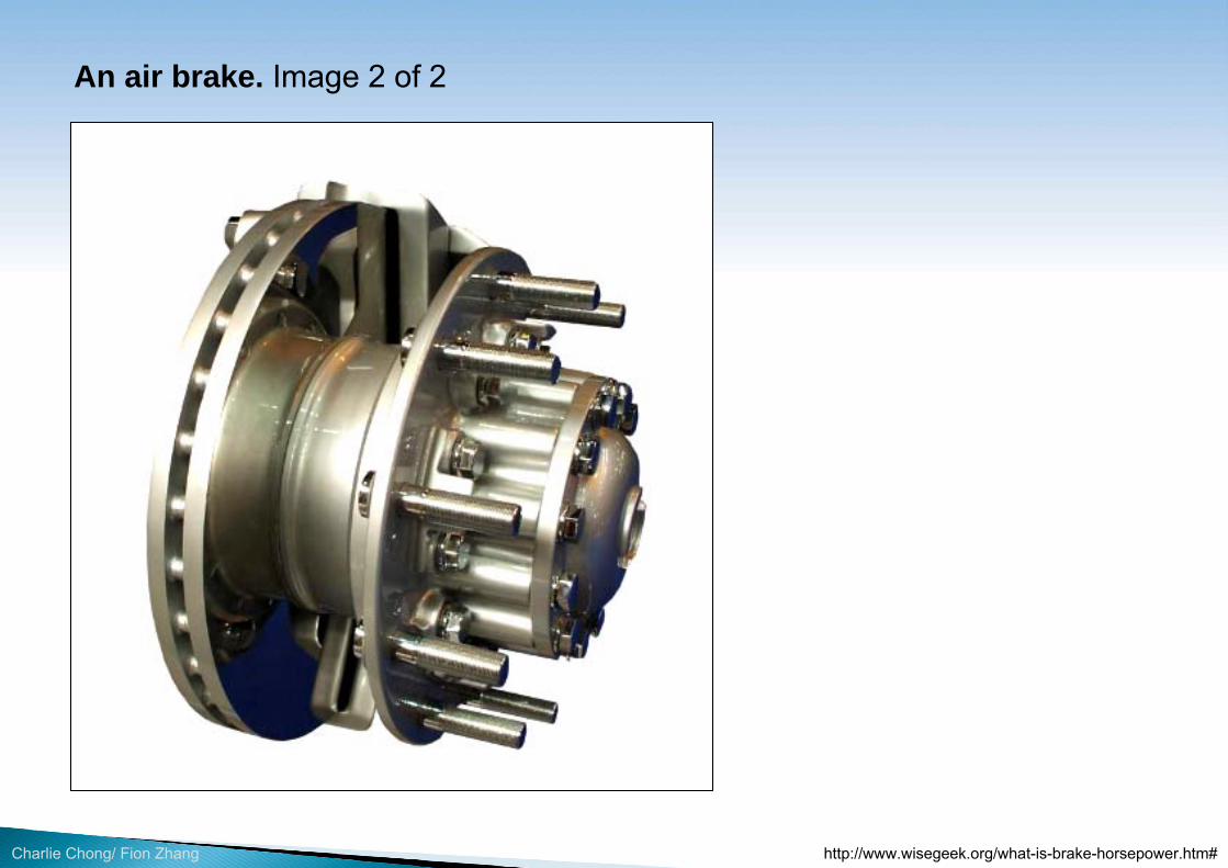
Charlie Chong/ Fion Zhang
An air brake. Image 2 of 2
http://www.wisegeek.org/what-is-brake-horsepower.htm#

Charlie Chong/ Fion Zhang
The purpose of pump performance test is to ensure that the actual performance of a pump is consistent with that set as adequate by the supplier.
Recorded test data usually consists of the following information: Test fluid temperature Test fluid specific gravity Torque (Power) reading Voltage at the driver Current to the driver
• Frequency of supply voltage • Flowrates• Discharge pressure • Suction pressure • Elevations corrections • Vibration levels. • Oil temperature

Charlie Chong/ Fion Zhang
A minimum of five points are taken to cover the flow range from 0 to 120%, depending on the test standard. For API-610 pumps these normally are: Shutoff (no vibration data required). Minimum continuous stable flow (beginning of allowable operating
region). Between 95% and 99% of rated flow. Between rated flow and 105% of rated flow. Approximately the best efficiency flow (if rated flow is not within 5% of
best efficiency flowrate). End of allowable operating region.

Charlie Chong/ Fion Zhang
The number of vibration readings taken depends also on the selected standard.
Once test is completed, all data have to be converted into suitable units, plotted on a chart and compared to the acceptance criteria.
Acceptance criteria usually cover tolerances on: Head, efficiency, flow rate, vibrations levels, brake horse power, speed
and oil temperatures in bearing housings.
If specified, the pump should be run on the test stand at the rated flow until oil temperature stabilization has been achieved. If specified, the pump should bemechanically run at the rated flow for 4 h.
Charlie Chong/ Fion Zhang
9.9 Equipment Disassembly Inspection 9.9.1 For certain kinds of rotating equipment, disassembly inspection is commonly performed to inspect the rotating equipment internals for contact during testing. Example, “disassembly due to the need to reduce impeller diameter by more than 5% to meet performance requirement requires a retest”.
9.9.2 If pump has anti-friction (ball or roller) bearings, oil should be drained from bearing housings and inspected on the subject of color change and foreign material inclusion. If pump has hydrodynamic bearings (sleeve and thrust), bearings should be removed and inspected after the test. 9.9.3 If it is necessary to disturb the mechanical seal assembly following the performance test, or if the test seal faces are replaced with the job seal faces, the final seal assembly should be air-tested.

Charlie Chong/ Fion Zhang
9.10 Surface Preparation/Coatings Inspections 9.10.1 Performance of coating systems typically depends on the how well the substrate or surface is prepared for coating applications. Typically on rotating equipment, visual inspection of surface preparation is recommended or required. Inspections typically consist of: Surface profile measurement. Visual surface comparison. Verification of blasting medium.

Charlie Chong/ Fion Zhang
9.10.2 Coating systems are usually specified in the contractual and engineering documents and likely will involve single or multi coating applications. The method of inspection of these coating systems is by the use of a dry film thickness gauge (DFT) per SSPC-PA 2, which the SI should be familiar with. 9.10.3 The SI should also be aware of specific coating requirements such as stripe coating of welds, edges, corners, etc. which are performed to insure coating performance on rough or uneven surfaces. 9.10.4 In addition to purchase order requirements and company standards, coating manufacturer’s recommendations will provide the details for correct coatings application to be followed. 9.10.5 Prior to releasing the rotating equipment for shipment, the source inspector should inspect the external coated or lined surfaces for the following items: raised areas, pinholes, soft spots, disbondment, delaminations, blisters, holidays, bubbling, fish-eyes, runs and sags, uniformity, mechanical damage, orange peel, adhesion, mud flat cracking and proper color or shade. For internal or spare coating the inspector would check for anti-fouling testing prior to babalnce (?) or testing.

Charlie Chong/ Fion Zhang
9.10.6 Any areas found in need of coating repairs should be properly identified and documented (NCR) by the source inspector as well as any testing and re-inspection performed after repairs have been made.

Charlie Chong/ Fion Zhang
10.0 Final Acceptance 10.1 Prior to Final Acceptance of Rotating Equipment Prior to final acceptance of rotating equipment, the source inspector should determine the following: All work specified in the contractual agreements is completed by the S/V. As-Built drawings, and datasheet have been completed and submitted to
purchaser. All NCRs have been closed out and resolved by the S/V QC
representative and owner’s QA representative. All punch list items have been completed. All Inspection related activities have been completed and documented. All S/V work has been deemed acceptable by the owner’s QA
representative in accordance with the requirements of codes, standards and project specifications.

Charlie Chong/ Fion Zhang
10.2 Shipping Preparations Shipping Preparations may also be specified in the contractual and engineering documents. It is important that the SI confirm that all bracing, strapping, mounting, covering, packaging, marking, and protection from the weather, etc. is effectively completed before the equipment is released for shipment. These are typically defined in the purchase agreement or attached as a requirement, which may be different project to project.
10.3 Reviewing Final S/V Data It is typical for the SI to perform a final review of the contractually required S/V data upon the completion of the manufacturing prior to shipment of the materials or equipment.

Charlie Chong/ Fion Zhang
This review is to determine that all documents are complete, with the as built item with all supporting documents as identified in the contractual agreement. Such documentation may include but is not limited to: Final drawings/data sheets MTR’s Performance Test documentation NDE results Product specific QC checks NCR close outs Certification documents Code compliance documentation as applicable

Charlie Chong/ Fion Zhang
11.0 Manufacturing and Fabrication Processes 11.1 General 11.1.1 The manufacturer/fabricator (S/V) is responsible for the quality of all their products, which includes not only good workmanship, but also compliance with all codes, standards and specifications contained in the contractual agreements. The source inspector is responsible as defined in the inspection and test plan (ITP) for performing the source quality surveillance activities at the S/V facilities in accordance with the applicable ITP.

Charlie Chong/ Fion Zhang
11.1.2 Specific processes that are commonly used include welding, heat treatment, casting, forming, forging, machining, assembly, etc. The source inspector needs to be familiar with those processes to confirm compliance with codes, standards and project document requirements. For all processes including rework and repair, the following information should be consistent and confirmed: Manufacturing and fabrication process has a documented method
describing how to perform the work. Individuals required to perform the process have proof of training and
qualifications. Individuals performing the work have immediate access to the relevant
procedures. There is acceptance criteria documented to determine if the processes
results are acceptable. The results of the processes are documented.
11.1.3 Rework and repair—should be approved by the purchaser and verified by the SI.

Charlie Chong/ Fion Zhang
11.2 Welding Processes and Welding Defects Different welding processes are susceptible to different types of welding defects. Hence it’s important for the SI to know which welding processes will be applied to the equipment during manufacturing/fabrication and to be familiar with the typical defects for each welding process that can occur. The SI should revert to the purchase agreement and S/V welding procedures as applicable.

Charlie Chong/ Fion Zhang
11.3 Casting 11.3.1 The casting process is used to create simple or complex shapes from any material that can be melted. This process consists of melting the material and heating it to a specified temperature, pouring the molten material into a mold or cavity of the desired shape, and solidification of the material to form the finished shape. An advantage of the casting process is that a single step process can be used to produce components that are characterized by one or more of the following attributes: Complex shapes e.g. fittings, flanges, valve bodies, pump cases. Hollow sections or internal cavities. Irregular curved surfaces. Very large sizes. Materials that are difficult to machine.

Charlie Chong/ Fion Zhang
11.3.2 A disadvantage of castings for pressure components is that mechanical properties such as toughness may not be adequate. Typical defects associated with the casting process that the SI should be aware of include: • Shrinkage voids. • Gas porosity. • Trapped inclusions.

Charlie Chong/ Fion Zhang
A disadvantage of castings for pressure components is that mechanical properties such as toughness may not be adequate.

Charlie Chong/ Fion Zhang
A disadvantage of castings for pressure components is that mechanical properties such as toughness may not be adequate.

Charlie Chong/ Fion Zhang
11.3.3 Castings are susceptible to the creation of voids during the casting process which could result in through wall leaks during service. ASTM grades of casting used in the petrochemical industry typically for pump casings and valve bodies are referenced in ASTM A703, Standard Specification for Steel Castings, General Requirements for Pressure Containing Parts.
This standard prohibits peening, plugging and impregnating defects in castings to stop leaks, as opposed to making more permanent welding repairs. The SI should make sure that any casting repairs needed are brought to his/her attention so that adequate repair procedures can be prepared, approved by the purchaser and implemented. ASTM 703 also provides casting grade symbols that identify the type of material in the casting.
ASTM A703

Charlie Chong/ Fion Zhang
11.3.4 Grade symbols are required on castings (e.g. WCB, WC9, CF8M, andso forth) in order to indicate the type of casting material. The SI should verify that the casting grade symbol on products e.g. valve bodies matches the specified grade in the contractual documents.
11.3.5 MSS-SP-55, Quality Standard for Steel Castings for Valves, Flanges and Fittings and Other Piping Components—Visual Method for Evaluation of Surface Irregularities is the standard that is generally used to perform visual evaluation of surface irregularities that may have occurred during the casting process. The source inspector accepting cast products should be familiar with this standard.
MSS-SP-55

Charlie Chong/ Fion Zhang
Casting

Charlie Chong/ Fion Zhang
Casting

Charlie Chong/ Fion Zhang
Casting

Charlie Chong/ Fion Zhang
11.4 Forging 11.4.1 Forging is the oldest known metal working process. It consists of a number of processes that are characterized by the use of localized compressive forces that are applied via hammers, presses, dies, or other forging equipment to induce plastic/permanent deformation. While forging may be performed in all temperature ranges, most forging is done above the recrystallization temperature of metal.
During the forging process the grain flow follows the general shape of the component and results in improved strength and toughness characteristics. Advantages of this change include: Increased wear resistance without increased hardness/loss of ductility. Stronger/tougher than an equivalent cast or machined component. Less expensive alloys can be used to produce high strength components. Components are not susceptible to common casting defects.

Charlie Chong/ Fion Zhang
11.4.2 ASTM A788, Standard Specification for Steel Forgings, General Requirements covers a group of common requirements that may be applied to steel forgings for general use. Key elements of ASTM A788 include the following: The purchaser may specify additional requirements. Tension and hardness tests must be conducted to evaluate mechanical
properties. Repair welding is not allowed unless permitted by the product specification. Supplementary general requirements may be performed by agreement
between the supplier and the purchaser; these requirements are designated by an S followed by a number (e.g. S5).
ASTM A788

Charlie Chong/ Fion Zhang
Forging
http://www.canforge.com/valves-pipeline-equipment/

Charlie Chong/ Fion Zhang
Forging
http://www.canforge.com/valves-pipeline-equipment/

Charlie Chong/ Fion Zhang
11.5 Machining 11.5.1 Machining is any of several metal working processes in which a piece of raw material is cut into a desired final shape and size by a controlled material-removal process. Typical fixed equipment components that requiremachining include: flanges, valve components, and heat exchanger tube sheets. The three principal machining processes are (1) turning, (2) drilling and (3) milling. Other machining operations include shaping, planing, boring, broaching and sawing. 11.5.1.1 Turning operations are operations that rotate the workpiece as the primary method of moving metal against the cutting tool. Lathes are the principal machine tool used in turning. 11.5.1.2 Milling operations are operations in which the cutting tool rotates to bring cutting edges to bear against the workpiece. Milling machines are the principal machine tool used in milling. 11.5.1.3 Drilling operations are operations in which holes are produced or refined by bringing a rotating cutter with cutting edges at the lower extremity into contact with the workpiece. Drilling operations are done primarily in drill presses but sometimes on lathes or mills.

Charlie Chong/ Fion Zhang
11.5.2 Machining requires attention to many details for a workpiece to meet the specifications set out in the engineering drawings or blueprints. Besides the obvious problems related to correct dimensions, there is the problem of achieving the correct finish or surface smoothness on the workpiece such a flange finish. Typically there is no in-process inspection by the SI for the machining operation; however, the SI may be required to check dimensional aspects and tolerances of machined components.
11.6 Assembly Assembly generally has more to do with machinery, instrumentation, control systems, and electrical gear. However, for mechanical equipment such as skid units and other equipment that is to be assembled e.g. flanges or other connections, the SI should be looking for tight fit up of all connectors. This can be accomplished with torque wrenches or “pinging” bolts with a small hammer (like a slag or ball peen hammer). The SI should check to make sure that bolted flanges and screwed fittings are leak free when witnessing performance tests.

Charlie Chong/ Fion Zhang
11.7 Metallurgy Issues Associated with Manufacturing and Fabrication Processes 11.7.1 The Structure and Metals Metallurgy is a complex science in which many schools have degreed programs, but a general understanding of the major principles is important to the source inspector, due to the wide variety of metals and alloys that may be used in manufacturing and fabrication processes including welding. 11.7.2 Physical Properties of Metals The physical properties of a metal or alloy are those, which are relatively insensitive to structure and can be measured without the application of force. Examples of physical properties of a metal are the melting temperature, the thermal conductivity, electrical conductivity, the coefficient of thermal expansion, and density.

Charlie Chong/ Fion Zhang
11.7.3 Mechanical Properties of Metals Engineers select materials of construction that provide adequate strength and toughness at operating temperatures and pressures. For the inspector, verification that mechanical properties meet the design requirements is essential. Inspectors should understand the underlying principles of mechanical properties and the nature of tests conducted to verify the value of those properties.
11.7.4 Hardness and Hardenability of Metals Hardenability is defined as that property of a ferrous alloy that determines the depth and distribution of hardness induced by quenching. It is important to note that there is not a close relationship between hardenability and hardness, which is the resistance to indentation. Hardness depends primarily on the carbon content of the material, whereas hardenability is strongly affected by the presence of alloying elements, such as chromium, molybdenum and vanadium, and to a lesser extent by carbon content and alloying elements such as nickel, copper and silicon.

Charlie Chong/ Fion Zhang
11.7.5 Weldability of Metals The American Welding Society defines weldability as “the capacity of a metal to be welded under the fabrication conditions imposed, into a specific, suitably designed structure, and to perform satisfactorily in the intended service.”
11.7.6 Preheating and Post Weld Heat Treatment 11.7.6.1 Preheating Preheating is defined as heating of the weld and surrounding base metal to a predetermined temperature prior to the start of welding. The primary purpose for preheating carbon and low-alloy steels is to reduce the tendency for hydrogen induced delayed cracking. It does this by slowing the cooling rate, which helps prevent the formation of martensite (a more crack prone microstructure) in the weld and base metal HAZ. According to B31.3, the pre-heat zone for welding of new process piping should extend at least one inch beyond the edge of the weld for piping.

Charlie Chong/ Fion Zhang
11.7.5 Weldability of Metals The American Welding Society defines weldability as “the capacity of a metal to be welded under the fabrication conditions imposed, into a specific, suitably designed structure, and to perform satisfactorily in the intended service.”
11.7.6 Preheating and Post Weld Heat Treatment 11.7.6.1 Preheating Preheating is defined as heating of the weld and surrounding base metal to a predetermined temperature prior to the start of welding. The primary purpose for preheating carbon and low-alloy steels is to reduce the tendency for hydrogen induced delayed cracking. It does this by slowing the cooling rate, which
helps prevent the formation of martensite (a more crack prone microstructure) in the weld and base metal HAZ. According to B31.3, the pre-heat zone for
welding of new process piping should extend at least 1 (one) inch beyond the edge of the weld for piping.

Charlie Chong/ Fion Zhang
11.7.6.2 Postweld Heat Treatment (PWHT) Postweld heat treatment (PWHT) produces both mechanical and metallurgical effects in carbon and low-alloy steels that will vary widely depending on the composition of the steel, its past thermal history, the temperature and duration of the PWHT and heating and cooling rates employed during the PWHT. The need for PWHT is dependent on manyfactors including; chemistry of the metal, thickness of the parts being joined, joint design, welding processes and service or process conditions. The temperature of PWHT is selected by considering the changes being sought in the equipment or structure. PWHT is the most common form of fabrication heat treatment applied to fixed equipment. When PWHT is required by code, typical normal holding temperatures for carbon and some alloy steels is 1,100°F for one hour per inch of thickness with 15 minute minimum. When PWHT is required for equipment due to in-service process considerations, those requirements will most likely be found in company standards and specified in the project documents.

Charlie Chong/ Fion Zhang
11.7.6.2 Postweld Heat Treatment (PWHT) Postweld heat treatment (PWHT) produces both mechanical and metallurgical effects in carbon and low-alloy steels that will vary widely depending on the composition of the steel, its past thermal history, the temperature and duration of the PWHT and heating and cooling rates employed during the PWHT. The need for PWHT is dependent on many factors including; chemistry of the metal, thickness of the parts being joined, joint design, welding processes and service or process conditions. The temperature of PWHT is selected by considering the changes being sought in the equipment or structure. PWHT is the
most common form of fabrication heat treatment applied to fixed equipment. When PWHT is required by code, typical normal holding temperatures for carbon and some alloy steels is 1,100°F for one hour per inch of thickness with 15 minute minimum. When PWHT is
required for equipment due to in-service process considerations, those requirements will most likely be found in company standards and specified in the project documents.

Charlie Chong/ Fion Zhang
Normally the appropriate PWHT for welded equipment and piping is specified in the welding procedure specification (WPS). Heating and cooling rates for PWHT may be specified in the construction code or project documents. Typically heating rates for pressure equipment and piping above 800°F must be controlled to no more than 400°F per hour with no variation permitted of more than 250°F in any 15 foot segment of the equipment. Thermocouples must be located in order to verify even distribution of temperature on components and to ensure that no component is over or under-heated during PWHT. Most of the information necessary for the source inspector to know and understand about PWHT is covered in ASME BPVC Section VIII, Division 1.
11.7.6.3 Other Heat Treatments Other heat treatments include annealing, normalizing, solution annealing, and tempering. See Section 3 for definitions of those heat treatments.

Charlie Chong/ Fion Zhang
Normally the appropriate PWHT for welded equipment and piping is specified in the welding procedure specification (WPS). Heating and cooling rates for PWHT may be specified in the
construction code or project documents. Typically heating rates for pressure equipment and piping above 800°F must be controlled to no more than 400°F per hour with no variation permitted of more than 250°F in any 15 foot segment of the equipment. Thermocouples must be located in
order to verify even distribution of temperature on components and to ensure that no component is over or under-heated during PWHT. Most of the information necessary for the source inspector to know and understand about PWHT is covered in ASME BPVC Section VIII, Division 1.
11.7.6.3 Other Heat Treatments Other heat treatments include annealing, normalizing, solution annealing, and tempering. See Section 3 for definitions of those heat treatments.

Charlie Chong/ Fion Zhang

Charlie Chong/ Fion Zhang
Learn About Compressor http://slideplayer.com/slide/1424554/

Charlie Chong/ Fion Zhang

Charlie Chong/ Fion Zhang

Charlie Chong/ Fion Zhang

Charlie Chong/ Fion Zhang

Charlie Chong/ Fion Zhang
Good Luck!