IAmLUG presentation: Domino Admin Best Practices - Hunting the Gremlins

1© 2005 Cisco Systems, Inc. All rights reserved.
SCTE Cable-Tec Expo 2005
Understanding and Troubleshooting Linear Distortions: Micro-reflections, Amplitude Ripple/Tilt and Group Delay
RON HRANAC

222© 2005 Cisco Systems, Inc. All rights reserved.
SCTE Cable-Tec Expo 2005
A Clean Upstream: Or Is It?
Graphic courtesy of Sunrise Telecom

333© 2005 Cisco Systems, Inc. All rights reserved.
SCTE Cable-Tec Expo 2005
Transmission Line Theory 101
Source LoadTransmission Medium
ZS = ZT = ZL
Source LoadTransmission Medium
ZS ? ZT ? ZL
Source LoadTransmission Medium
ZS ? ZT ? ZL

444© 2005 Cisco Systems, Inc. All rights reserved.
SCTE Cable-Tec Expo 2005
Impedance Mismatches
Source(7 dB return loss)
Load(7 dB return loss)
Transmission Medium(1 dB attenuation)
+31 dBmVat time T0
+30 dBmVat time T1
+22 dBmV
+15 dBmV
+23 dBmV
+14 dBmV(-16 dBc)at time T2
+30
+25
+20
+15
+10
+5
Am
plitu
de(d
Bm
V)
Time (T)
Incident signal (T1) Echo (T2)
+14 dBmV
+30 dBmV
234 ns
100 ft23 20

555© 2005 Cisco Systems, Inc. All rights reserved.
SCTE Cable-Tec Expo 2005
Micro-reflections—The Big Picture
Time (T)
Am
plitu
de
Peak (+31.28 dBmV)
Null (+28.5 dBmV).
.
Frequency (F)
Am
plitu
de(d
Bm
V)
~4.27 MHz+30+25
+20+15
+10+5
Am
plitu
de(d
Bm
V)
Time (T)
Incident signal (T1) Echo (T2)
+30 dBmV
+14 dBmV (-16 dBc)234 ns
Echo calculation courtesy of Holtzman, Inc.

666© 2005 Cisco Systems, Inc. All rights reserved.
SCTE Cable-Tec Expo 2005
Micro-reflections
• Damaged or missing end-of-line terminators
• Damaged or missing chassis terminators on directional coupler, splitter, or multiple-output amplifier unused ports
• Loose center conductor seizure screws
• Unused tap ports not terminated; this is especially critical on low value taps, but allunused tap ports should be terminated with 75-ohm terminations (locking terminators without resistors or stingers do not terminate the tap port)
• Poor isolation in splitters, taps and directional couplers• Unused customer premises splitter and directional coupler ports not terminated• Use of so-called self-terminating taps at feeder ends-of-line; these are the equivalent
of splitters, and do not terminate the feeder cable unless all tap ports are terminated• Kinked or damaged cable (includes cracked cable, which causes a reflection and
ingress)• Defective or damaged actives or passives (water-damaged, water-filled, cold solder
joint, corrosion, loose circuit board screws, etc.)• Cable-ready TVs and VCRs connected directly to the drop (return loss on most cable-
ready devices is poor)• Some traps and filters have been found to have poor return loss in the upstream,
especially those used for data-only service
Causes:

777© 2005 Cisco Systems, Inc. All rights reserved.
SCTE Cable-Tec Expo 2005
Amplitude Ripple/Tilt
• Amplitude ripple and tilt are known in cable industry vernacular as frequency response, and can refer to in-channel frequency response or the frequency response across a specified RF bandwidth such as 5-42 MHz
• The causes include gremlins such as improper network alignment and impedance mismatches (micro-reflections!)
Graphics courtesy of Acterna and Sunrise Telecom
Combination of amplitude ripple and tilt
Amplitude tilt, slight amount of ripple
Amplitude tilt

888© 2005 Cisco Systems, Inc. All rights reserved.
SCTE Cable-Tec Expo 2005
Amplitude Ripple/Tilt
• This 6.4 MHz bandwidth A-TDMA digitally modulated signal exhibits severe in-channel amplitude tilt at the CMTS upstream input
• Adaptive equalization (pre-equalization) in the cable modem is able to compensate for nearly all of the amplitude tilt
Adaptive equalization
999© 2005 Cisco Systems, Inc. All rights reserved.
SCTE Cable-Tec Expo 2005
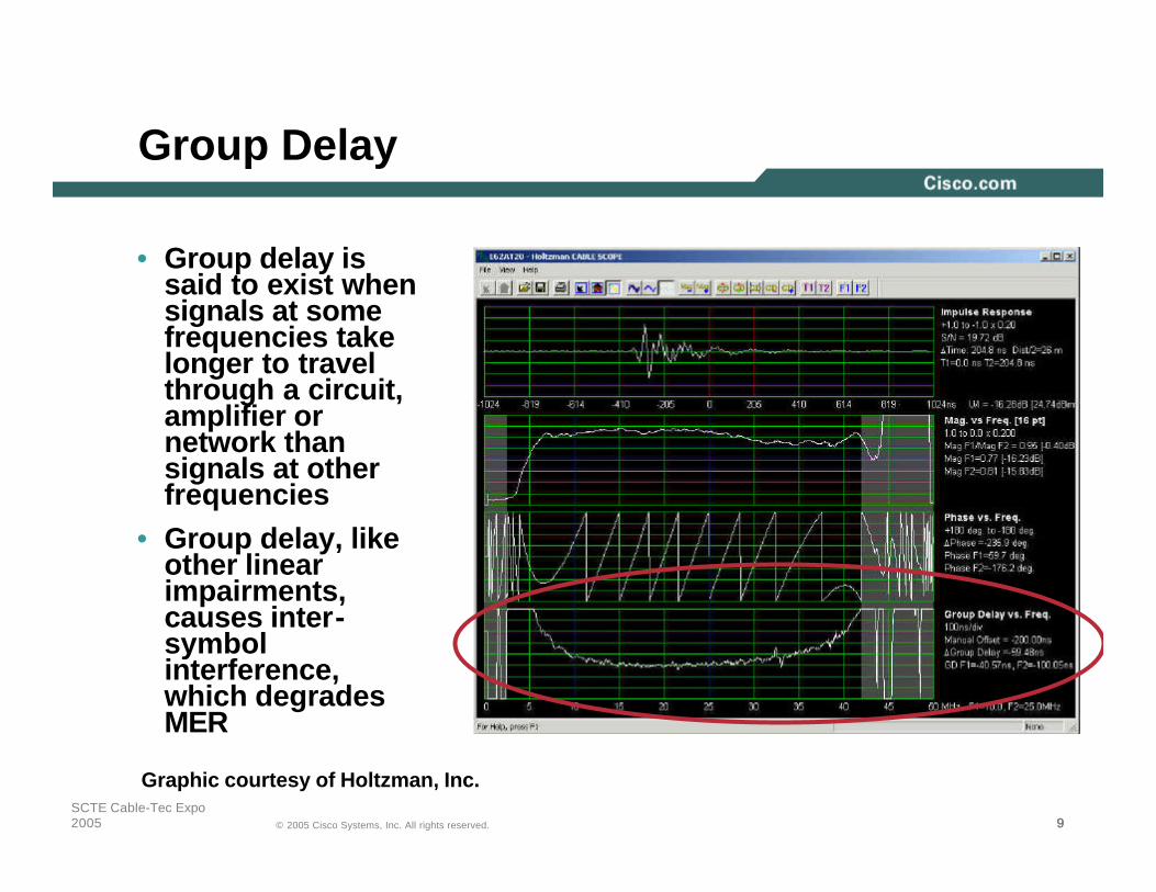
Group Delay
• Group delay is said to exist when signals at some frequencies take longer to travel through a circuit, amplifier or network than signals at other frequencies
• Group delay, like other linear impairments, causes inter-symbol interference, which degrades MER
Graphic courtesy of Holtzman, Inc.

101010© 2005 Cisco Systems, Inc. All rights reserved.
SCTE Cable-Tec Expo 2005
Linear Distortions in the Real World
• In this example, an echo at ~485 ns causes visible amplitude ripple across the 5-42 MHz spectrum
• Group delay ripple also is present
Graphic courtesy of Holtzman, Inc.
Echo
Amplitude ripple
Group delay ripple

111111© 2005 Cisco Systems, Inc. All rights reserved.
SCTE Cable-Tec Expo 2005
Linear Distortions in the Real World
• Here’s another example: An approx. -33 dBc echo at just over 1 µs
• This echo meets the DOCSIS® upstream -30 dBc at >1.0 µsecparameter
• Here, too, the echo is sufficient to cause some amplitude and group delay ripple
Graphic courtesy of Sunrise Telecom

121212© 2005 Cisco Systems, Inc. All rights reserved.
SCTE Cable-Tec Expo 2005
A Clean Upstream: Or Is It?
• Remember the upstream slide at the beginning of this presentation?
• Here’s why 16-QAM wouldn’t work
Graphic courtesy of Sunrise Telecom

131313© 2005 Cisco Systems, Inc. All rights reserved.
SCTE Cable-Tec Expo 2005
A Clean Upstream: Or Is It?
• This upstream constellation shows a not-so-good 16-QAM signal
• UnequalizedMER is 21.3 dB, close to the failure threshold for 16-QAM
Graphic courtesy of Sunrise Telecom

141414© 2005 Cisco Systems, Inc. All rights reserved.
SCTE Cable-Tec Expo 2005
A Clean Upstream
Graphics courtesy of Sunrise Telecom
From a linear distortion perspective, this is what a relatively unimpaired upstream looks like

151515© 2005 Cisco Systems, Inc. All rights reserved.
SCTE Cable-Tec Expo 2005
Wrapping Up
• Linear distortions are real problems in cable networks, and can seriously affect downstream and upstream data transmission
• Among the tools available to troubleshoot linear distortions are
Forward and reverse sweep, set to the maximum supported resolutionAdaptive equalization (DOCSIS 1.1 and 2.0 modems)CMTS tools such as per-modem SNR (MER), FEC error informationAvoid upstream frequencies above about 35 MHz to minimize diplex filter-related group delay
Use of specialized test equipment to characterize and troubleshoot micro-reflections, amplitude and group delay ripple
• An understanding of linear distortions is critical to achieving the reliability necessary for new services being deployed on today’s cable networks


![GREMLINS (1984) by Chris Columbus [1982.04.27] [2nd] [Scan]](https://static.fdocuments.us/doc/165x107/56d6be001a28ab30169033af/gremlins-1984-by-chris-columbus-19820427-2nd-scan.jpg)