Understanding and Managing Power System Harmonicswith switch-mode power supplies (SMPS), high- 22...
58
XUSACERL Technical Report FEO9 -10 April 1994 US Army Corps of Engineers Construction Engineering Research Laboratories AD-A280 627 Understanding and Managing Power System Harmonics by Franklin H. Holcomb Steve J. Briggs The application of nonlinear electrical loads has C increased dramatically in recent years. These loads include computers and other equipment E ECTE with switch-mode power supplies (SMPS), high- 22 190A efficiency fluorescent lighting systems with elec- tronic ballasts, and adjustable-speed drives with power electronic convertors. All these loads have nonlinear voltage-current characteristics, and all produce harmonic distortion on the power system. Harmonic currents in the power system can =DCI QUALMTY INSPECTED S cause unusual effects in the wiring and surround- ing power equipment. These effects include the overheating of wires, circuit breakers, transform- ers, and other equipment, the nuisance tripping of breakers, the saturation of various magnetic components in the system, and the creation of voltage distortion for all joining and connecting loads. This report offers a comprehensive overview of power system harmonics. It includes the causes, 94-19037 effects, and mitigation procedures for harmonic voltages and currents. Field engineers and designers of new facilities will find this report useful. Approved for public release; distribution is unigmited. "2JO /
Transcript of Understanding and Managing Power System Harmonicswith switch-mode power supplies (SMPS), high- 22...

XUSACERL Technical Report FEO9 -10April 1994
US Army Corpsof EngineersConstruction EngineeringResearch Laboratories AD-A280 627
Understanding and Managing PowerSystem Harmonics
by
Franklin H. HolcombSteve J. Briggs
The application of nonlinear electrical loads has Cincreased dramatically in recent years. Theseloads include computers and other equipment E ECTEwith switch-mode power supplies (SMPS), high- 22 190Aefficiency fluorescent lighting systems with elec-tronic ballasts, and adjustable-speed drives withpower electronic convertors. All these loads havenonlinear voltage-current characteristics, and allproduce harmonic distortion on the powersystem.
Harmonic currents in the power system can =DCI QUALMTY INSPECTED Scause unusual effects in the wiring and surround-ing power equipment. These effects include theoverheating of wires, circuit breakers, transform-ers, and other equipment, the nuisance trippingof breakers, the saturation of various magneticcomponents in the system, and the creation ofvoltage distortion for all joining and connectingloads.
This report offers a comprehensive overview ofpower system harmonics. It includes the causes, 94-19037effects, and mitigation procedures for harmonicvoltages and currents. Field engineers anddesigners of new facilities will find this reportuseful.
Approved for public release; distribution is unigmited. "2JO /

BestAvailable
Copy

The contents of this report are not to be used for advertising, publication,or promotional purposes. Citation of trade names does not constitute anofficial endorsement or approval of the use of such commercial products.The findings of this report are not to be construed as an officialDepartment of the Army position, unless so designated by other authorizeddocuments.
DESTROY THIS REPORT WHEN IT IS NO LONGER NEEDED
DO NOT RETURN IT TO THE ORIGINATOR

USER EVALUATION OF REPORT
REFERENCE: USACERL Technical Report FE-94/10, Understanding and Managing Power SystemHarmonics
Please take a few minutes to answer the questions below, tear out this sheet, and return it to USACERL.As user of this report, your customer comments will provide USACERL with information essential forimproving future reports.
I. Does this report satisfy a need? (Comment on purpose, related project, or other area of interest forwhich report will be used.)
2. How, specifically, is the report being used? (Information source, design data or procedure,management procedure, source of ideas, etc.)
3. Has the information in this report led to any quantitative savings as far as manhours/contract dollarssaved, operating costs avoided, efficiencies achieved, etc.? If so, please elaborate.
4. What is your evaluation of this report in the following areas?
a. Presentation:
b. Completeness:
c. Easy to Understand:
d. Easy to Implement:
e. Adequate Reference Material:_
f. Relates to Area of Interest:
g. Did thz report meet your expectations?
h. Does the report raise unanswered questions?

i. General Comments. (Indicate what you think should be changed to make this report and futurereports of this type more responsive to your needs, more usable, improve readability, etc.)
5. If you would like iu be contacted by the personnel who prepared this report to raise specific questions
or discuss the topic, please fill in. the following information.
Name:
Telephone Number:
Organization Address:
6. Please mail the completed form to:
Department of the ArmyCONSTRUCTION ENGINEERING RESEARCH LABORATORIESATTN: CECER-IMTP.O. Box 9005Champaign, IL 61826-9005

REPORT DOCUMENTATION PAGE 0 @0704.013IOMB No. 070401811
Pudi repofing burdei for Mh mledlon of nIonnaion Is umemed to mwe I hour per respons, Indldlng the Imi for rweedng Inustuctone. seewg r idng dew souraps,gOWhtng and whdealdk* the do@ needed, sand conipisun end rselW~k tn otcheoedon of wdoneridon. Send aomme niegsardni INs burden esimete or any Other upped di Oft.'le'_on of Wdomaiion. kochdl. maggeedens for redudaig this burden. to WssWnglo Headquarters Servicee. Otremorote for Intusin Operedons and Reports. 1215 JefbrsoD"1 ghwes. Stite 1204. ArIngton. VA 04, snd Io the O1110e of MaWne and mid , B Pe Redjon Pmod (0704-01SI). W ,~n. DC20
I. AGENCY USE ONLY (Leave Blank) 2. REPORT DATE 3. REPORT TYPE AND DATES COVERED
April 1994 Final4. TITLE AND SUBTITLE 5. FUNDING NUMBERS
Understanding and Managing Power System Harmonics PREP E87910442
6. AUTHOR(S)Franklin H. Holcomb and Steve J. Briggs
7. PERFORMING ORGANIZATION NAME(S) AND ADDRESS(ES) 8. PERFORMING ORGANIZATIONU.S. Army Construction Engineering Research Laboratories (USACERL) REPORT NUMBERP.O. Box 9005 TR FE-94/10Champaign, IL 61826-9005
9. SPONSORINGAMONITORING AGENCY NAME(S) AND ADDRESS(ES) 10. SPONSORINGRMONITORINGU.S. Army Center for Public Works (USACPW) AGENCY REPORT NUMBERATTN: CECPW-K7701 Telegraph RoadAlexandria, VA 22310-3862
11. SUPPLEMENTARY NOTES
Copies are available from the National Technical Information Service, 5285 Port Royal Road, Springfield, VA22161.
12a. DISTRIBUTION/AVAILABILITY STATEMENT 12b. DISTRIBUTION COOEApproved for public release; distribution is unlimited.
13. ABSTRACT (Maximum 200 words)
The application of nonlinear electrical loads has increased dramatically in recent years. These loads includecomputers and other equipment with switch-mode power supplies (SMPS), high-efficiency fluorescent lightingsystems with electronic ballasts, and adjustable-speed drives with power electronic convertors. All these loadshave nonlinear voltage-current characteristics, and all produce harmonic distortion on the power system.
Harmonic currents in the power system can cause unusual effects in the wiring and surrounding powerequipment. These effects include the overheating of wires, circuit breakers, transformers, and other equipment,the nuisance tripping of breakers, the saturation of various magnetic components in the system, and the creationof voltage distortion for all joining and connecting loads.
This report offers a comprehensive overview of power system harmonics. It includes the causes, effects, andmitigation procedures for harmonic voltages and currents. Field engineers and designers of new facilities willfind this report useful.
14. SUBJECT TERMS 15. NUMBER OF PAGES
power system harmonics 56harmonic currents
16. PRICE CODE
17. SECURITY CLASSIFICATION 18. SECURITY CLASSIFICATION 19. SECURITY CLASSIFICATION 20. LIMITATION OF ABSTRACTOF REPORT OF THIS PAGE OF ABSTRACT
Unclassified Unclassified Unclassified SAR
NSN 7540-01-260-5500 Standwd Form 296 (Rev. 2-09)presmred by ANII t M-Il2W-l0

FOREWORD
This r-csearch was performed for the U.S. Army Center for Public Works (USACPW), PowerReliability Enhancement Program (USACPW-PREP), under customer order number E87910442, "Effectsof Electrical Loads." The USACPW-PREP technical monitors were Dr. Harold Hollis and Mike Bartos,CECPW-K.
The research was performed by the Energy and Utility Systems Division (FE) of the InfrastructureLaboratory (FL), U.S Army Construction Engineering Research Laboratories (USACERL). Part of thework was performed under contract by the Institute of Gas Technology (IGT), Chicago, and by Enviro-Management Research (EMR) of Springfield, VA. Dr. David Joncich is Chief, CECER-FE. Dr. MichaelJ. O'Connor is Chief, CECER-FL.
LTC David J. Rehbein is Commander of USACERL and Dr. L.R. Shaffer is Director.
Acce2!on For
NTIS CRA&IDTIC TABUnan'no•J;ced [
jucL ifiction -................ ..............
By --.-.----.-...............-----Diýt- ib ,tio•"
AvalbilitY Codes
Dist spý o
2

CONTENTS
Page
SF298 1FOREWORD 2LIST OF FIGURES AND TABLES 5
INTRODUCTION ................................................... 7BackgroundObjectiveApproachScope
2 DEFINITIONS AND CONCEPTS ........................................ 8HarmonicsResonanceTotal Harmonic DistortionHarmonic Limits
3 SOURCES OF HARMONICS AND SYSTEM RESPONSE CHARACTERISTICS ... 12Sources of HarmonicsSystem Response Characteristics
4 EFFECTS OF HARMONICS .......................................... 15Thermal StressInsulation StressLoad DisruptionEffects of Harmonics on Power System Equipment
5 HARMONIC DISTORTION LIMITS .................................... 18Need for Harmonic Analysis StudyHarmonic Distortion Levels
6 ASSESSING POWER SYSTEM PROBLEMS ............................... 22Site InspectionFactors to Consider in Evaluating Inspection FindingsMeasurement of Power System HarmonicsInstrumentation
7 GENERIC GUIDELINES FOR TROUBLESHOOTING HARMONIC PROBLEMS.. 33Troubleshooting Harmonic ProblemsTroubleshooting Charts
8 CRITERIA FOR NEW AND EXISTING POWER SYSTEMS DESIGNS .......... 38New Power System DesignExisting Power SystemMiscellaneous
9 SAFETY PRACTICES ............................................... 41Personnel SafetyRules for Preventing Electrical Accidents
3

CONTENTS (Cont'd)Page
Testing of Electrical Circuits and/or EquipmentUse and Can of Rubber Gloves for Electuical WorkInspection of Rubber Gloves (All Classes)Use of Low-Voltage TesterEffects of Electrical ShockFirst AidProper Treatment of Shock
10 ECONOMIC ANALYSIS AND COSTS ..................................... 48Cost Versus Savings
REFERENCES S1
D ISTRIBUTION
4

FIGURES
Number Page
2-1 Sine Wave 8
2-2 Harmonic Distortion and Phase 9
2-3 Resonance Due to Power-Factor-Correcting Capacitors 10
5-1 Example of Line Notching from an ac-to-dc Convertor 20
5-2 Reactance Distribution for an ac-to-dc Convertor 21
6-1 Recommended Power Monitor Hookup Procedure for Single-Phase Application 26
6-2 Recommended Power Monitor Hookup Procedure for Single-Phase ApplicationWith Power Conditioner 27
6-3 Recommended Procedure for 3-Phase Wye Application 27
6-4 Neutral-to-Ground Voltage for a Single-Phase Electronic Load 28
6-5 Neutral-to-Ground Spectrum Analysis for a Single-Phase Electronic Load 28
6-6 Neutral-To-Ground Voltage for a 3-Phase Electronic Load 29
6-7 Neutral-To-Ground Spectrum Analysis for a 3-Phase Electronic Load 29
7-1 Troubleshooting Harmonics Problems: Overview Chart 35
TABLES
3-1 Typical Harmonic Current Magnitudes 13
5-1 Current Distortion Limits for Distribution Systems (120 V - 69,000 V) 20
5-2 Voltage Distortion Limits for Distribution Systems (120 Volts - 69000 Volts) 21
6-1 Recommended Test Instruments for Conducting a Site Survey 32
7-1 Inspecting Equipment Bonds 36
7-2 Measuring Neutral Current and Voltage 36
7-3 Measuring Power-Line Voltage 36
7-4 Inspecting and Measuring Transformer Current and Voltage 37
7-5 Inspecting and Measuring Electrical Panel Voltage and Current 37
7-6 Assessing Noise Problems 37
5
TABLES (Cont'd)
Number Page
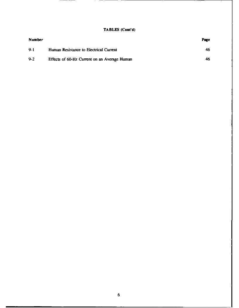
9-1 Human Resistance to Electrical Current 46
9-2 Effects of 60-Hz Current on an Average Human 46
6

UNDERSTANDING AND MANAGING POWER SYSTEM HARMONICS
I INTRODUCTION
Background
Power system harmonics are an increasingly serious problem due to their damaging effects on userloads and on the power network. Power losses due to harmonics also have an associated energy cost.Harmonics problems can be traced to two industry trends: (1) a dramatic increase in the use of nonlinearloads, such as static power converters (rectifiers), switching power supplies, and other electronic loads,and (2) a significant change in the design philosophy of all power apparatus and load equipment.Manufacturers are now designing power devices and load equipment with minimum design marginscompared to those margins used only a few years ago. In iron core devices, for example, the operatingpoints exhibit more nonlinear characteristics, resulting in a substantial increase in harmonics. Considerableattention has been paid to the higher harmonic frequencies that cause interference with communication andtelephone circuits, but very little attention has been paid to lower-frequency bands that cause heating inelectrical devices and apparatus.
Objective
This report provides information and guidance to engineers and technicians who install, operate,troubleshoot, and maintain AC power systems that supply linear and nonlinear loads.
Approach
This report contains several chapters. Chapter 2 defines harmonics, resonance, and total harmonicdistortion. Chapter 3 describes the sources of harmonics and their system-response characteristics, neededfor understanding their behavior relative to power system elements. Chapter 4 provides information onthe effects of harmonics on power system elements and equipment. Chapter 5 discusses the criteria forthe limits of harmonic distortion in the power system. Chapter 6 describes survey procedures andinstrumentation for assessing power system problems. Chapter 7 provides generic guidelines and flowcharts for troubleshooting harmonic and noise problems. Procedures are described for checking grounds(including the facility ground system) and common-mode noise. Chapter 8 provides criteria for newpower system designs and the rehabilitation of existing installations. These criteria are recommended foruse at Command, Control, Communication, and Intelligence (C31) facilities. Chapter 9 outlines safetyprecautions for personnel doing troubleshooting. Chapter 10 outlines the costs of electrical powerdistribution equipment used for mitigating harmonics, and also discusses cost benefit analysis of themitigating equipment.
Scope
This report addresses harmonics problems in existing facilities as well as those introduced in thedesign process.
7

2 DEFINITIONS AND CONCEPTS
Huge amounts of electronic equipment (e.g., computers, microprocessor-based communicationssystems, safety and security systems, and facsimile equipment) are being used in new and existing U.S.Army facilities. Most of this equipment is affected by harmonics because these power systems are notdesigned for nonlinear loads. These problems range from overloading of the phase and neutral conductorsof the power distribution system to premature failure of electrical equipment because of overheating. Anunderstanding of basic definitions and concepts is necessary to correctly identify problems and solutions.
Harmonics
Harmonics are voltages and currents present on an electrical system at some multiple of thefundamental frequency (60 Hz). such as the 2nd (120 Hz), 3rd (180 Hz), and 5th (300 Hz). To understandharmonics, it is important to understand the nature of "clean" power. Clean power implies that the currentand voltage waveforms of the power system are pure sine waves, as shown in Figure 2-1.
A sine wave is the plot over time of the sine of the angle (0) that a vector (M) rotating at auniform speed through a full revolution of 360 degrees makes from a start or zero degree position. Thiswaveform contains only one frequency component whose period is the time of on - rotation (revolution)and whose maximum amplitude is M. The positive maximum occurs when 0 is 90 degrees (sin 900=1),and the negative maximum occurs when 0 is 270 degrees (sin 2700=-1). Similarly, the amplitude is zerowhen 0 is 0 degrees at the start, at 180 degrees (at half-cycle), and at 360 degrees (at the end of onecycle). Its period is the time it takes for the vector M to complete one revolution. The frequency of thissinusokida waveform is 1/period. The frequency of power in the United States is maintained at 60 cyclesper second (60 Hz). In real power systems, however, there is always some distortion of voltage andcurrent waveforms. As such, the waveforms are not totally a sine wave. This deviation is equivalent toadding one or more sine waves of different frequency. The sine waves that distort a power system areintegral (whole-number) multiples of the fundamental power frequency. These whole-number multiplesare called "harmonics" of the fundamental. The distortion caused by superimposing or adding harmonics
I PERIOD (SEC)1 REVOLUTION
900
o %
M % -400-- - - - - 0 2oM M 1/
I I0--18-0 .. .t 1 ,360° 00, I/3 0
I / /
• / /% -
2700
Figure 2-1. Sine Wave.
8

to the fundamental sine wave is determined by their frequency and by their amplitude and timing (orphase) relationship to the fundamental. Figure 2-2 illustrates 3rd harmonic distortion. In (A), the 3rdharmonic is one-third the amplitude and in-phase with the fundamental. In (B), the 3rd harmonic is one-third the amplitude and 180 degrees out of phase with the fundamental.
The composite waveform in Figure 2-2 (A) is relatively flat (square) compared to the peakedwaveform in (B). The difference is due solely to the phase of the 3rd harmonic. Both waveforms,however, contain the same frequencies and the same amplitudes, and both have the same root mean square(rms) values. The composite waveform shown in Figure 2-2(A) is a sine wave whose peaks are clippedby the 3,d (odd) harmonic. Clipping can occur, for example, at load saturation when an increase involtage does not produce a proportional increase in current. Such nonlinear behavior distorts the currentwaveform by introducing odd harmonics. This is why the many nonlinear loads in today's power systemscause harmonics.
Resonance
To improve the load-power factor of the electrical power system, the common practice is to addshunt-connected capacitors at the main substation to correct for the inductive loads (transformers, motors,etc.). Although shunt-connected capacitors may improve the power factor, they may also create seriousproblems, particularly when harmonics are present. Any capacitance and inductance forms a circuit tuned(capacitance and inductive reactance are equal) to what is called the "resonant" frequency. If enoughharmonic energy is present and its frequency matches that of the rcsonant circuit, then a very large current(many times the original harmonic current) will flow. This current will produce extreme voltage dropsacross all circuit elements, blowing fuses, damaging components, and deflecting an excessively highharmonic level back into the power system. Resonance often occurs when shunt capacitors are locatednear a harmonic current source and, thus, create a parallel resonant circuit with the equivalent system
FUNDAMENTAL
PURESINEWAVE
IV I V I
III I I IIII 11 V I
HARMONIC V . kji'I -1/3V I
, ,
HARMONICALLY I I
DISTORTED' ' '
SINEWAVE
(A) (B)3RD HARMONIC 3RD HARMONIC "180'
"IN PHASE* OUT OF PHASE"
Figure 2-2. Hmnonic Distortion anO Phase.
9

impedance of the power system, as shown in Figure 2-3. System response characteristics under resonanceconditions are discussed in Chapter 3.
Total Harmonic Distortion
The total harmonic distortion (THD) is defined as the square root of the sum of the squares ofamplitude of all harmonic voltages or current divided by the amplitude of the fundamental voltage orcurrent, expressed in percent. It is calculated as follows:
I nI]q1THD (%) = (Vk)' X 1
V1 ^Sk-2
where:V1 = voltage at the kth harmonicV1 = fundamental frequency voltagen = order of harmonics.
The THD is used to quantify the effect of the harmonics on the power system voltage or current TheTHD is a rough measure of how distorted the waveform is compared to a pure sine waveform.
Harmonic Limits
The harmonic limits for current and voltage distortion are discussed in detail in Chapter 5. Thecriteria on which the harmonic limits are based can be classified into the following three groups:
1. Voltage distortions are limited to a maximum value. This method of harmonic limitation is usedprimarily to protect electronic loads, instrumentation, and electrical power distribution equipment againstthe harmful effects of harmonics. As discussed before, maintaining the THD factor in the range of 3 to
-444R
ACRPOWERSOURCEOrýh J
HARMONIC
CURRENT SHUNT HARMONICMAGNITUDE CAPACITORS GENERATING
c LOAD
14IGH HARMONICCURRENT FEEDBACK
INTO THE SYSTEM
Figure 2-3. Resonance Due to Power-Factor-Correcting Capacitors.
10

10 percent is a first step in protecting performance and ensuring the long lifespan of a wide range ofelectrical equipment.
2. Injected current harmonics are limited to maximum values that depend on the "stiffness" of thepower system. The usual cause of voltage distortion is the flow of nonsinusoidal currents. Currentharmonics also upset communication systems. Therefore, it is important to set limits on current harmonicsto keep the electromagnetic interference (EMI) and the active losses within tolerable limits.
3. Both voltage and injected current are limited to minimize the effects of the harmonics on loadequipment and power distribution equipment. In summary, limiting both the voltage and the currentharmonics will minimize their harmful effects. These effects are discussed in more detail in Chapter 4.
11

3 SOURCES OF HARMONICS AND SYSTEM RESPONSE CHARACTERISTICS
Power system harmonics can seriously degrade equipment performance and overall power quality.A brief discussion of sources of harmonics and system response characteristics follows.
Sources of Harmonics
Harmonics are generated by any load that draws current that is not proportional to the appliedvoltage. These include transformers during energization, motors with fractional pitch windings, andnonlinear loads. Power systems containing nonlinear circuit elements carry currents that are nonsinusoidal(not a pure sine wave), even when the applied voltage is a pure sine wave. Most loads are somewhatnonlinear, especially electronic loads that do not draw a continuous current, loads that are switched on foronly part of the cycle. Such loads create considerable harmonic distortion on the power system. Table3-I shows typical harmonic currents for several types of loads.
Power electronics, a major source of harmonics, are being used in devices ranging from smallappliances to huge convertors on the power system. The power rectifier, widely used in power electronicsfor converting AC to DC, causes switching within a cycle. These circuits are nonlinear and draw currentsof high harmonic content from the source.
System Response Characteristics
The nonlinear loads discussed in this chapter can be represented as current sources of harmonics.The harmonic voltage distortion on the power system depends on the impedance-versus-frequencycharacteristics in these harmonic current sources. The factors that affect the system frequency-responsecharacteristics are discussed below. These factors should be considered when evaluating a system.
Load Characteristics
Resistive loads provide a damping effect and reduce the magnification of harmonic levels nearparallel resonance frequencies. Inductive loads, such as motors, which contribute to the short-circuitcapacity of the system, can shift the resonance frequency. Inductive loads do not provide significantdamping.
Capacitor Banks
Capacitor banks, such as those used for power-factor improvement (reactive var compensation) andfor commutation of some static converters, affect system frequency response characteristics. Becausecapacitors can cause resonance conditions, they magnify harmonic levels. Power-factor improvementcapacitors, normally installed at the main substation, may contribute to harmonics problems on the lineside, as opposed to the load side.
Insulated Cables
The line-charging capacitance of insulated cables acts as a parallel circuit with the system inductancesimilar to that of capacitors. Therefore, insulated cables also affect system frequency-response character-istics, but not as much as shunt-connected capacitors do.
12

Table 3-1
Typical Harmonic Current Magnitudes
Transformer Inrush DC, up to several times Rated Load CurrentFundamental, up to several times Rated Load Current2nd, up to 67% Rated Load Current3rd. up to 23% Rated Load Current4th, 5th, up to 8% Rated Load Current
Transformer Magnetizing 1st, 0.5 to 2% of Rated Load Current3rd, up to 80% of Fundamental Magnetizing Current5th. up to 55% of Fundamental Magnetizing Current7th. up to 35% of Fundamental Magnetizing Current
Motors Up to 3% of Rated Load Current at the 2/5, 4/5, 8/5, 22/5 and32/5 harmonics due to rotor and pole imbalances
Arc Furnaces Order Steady Melting Boring In2 4.5% up to 50%3 4.7% up to 50%4 2.8% up to 30%5 4.5% up to 50%6 1.7%7 1.6% up to 30%8 1.1%9 1.0%10 1.0%
Fluorescent Lighting Neutral current is almost entirely 3rd harmonic, can exceedLine Current
3-Phase Converters Order Magnitude5 up to 20%7 up to 14%11 up to 9%13 up to 8%17 up to 6%19 up to 5%23 up to 4%25 up to 45%
l-Phase Converters Order Magnitude2 up to 50%3 up to 33%4 up to 25%5 up to 20%6 up to 17%7 up to 14%
Resonance Conditions
Harmonic currents generated by nonlinear load currents flow toward the lowest impedance. Usuallythe system impedance (utility) is much lower than the parallel impedance paths of the loads. However,the harmonic current will divide according to the impedance ratio of the system impedance and the parallel
13

impedance paths of the loads. When shunt capacitors ame connected in the distribution system, the systemoffers a very low impedance path to higher-frequency harmonic currents. Parallel resonance occurs whenthe system inductive reactance is equal to the capacitative reactance of the shunt-connected capacitors atone of the characteristic harmonic frequencies generated by the nonlinear load. Under these conditions,the harmonic current is magnified. This high current causes voltage distortion and telephone interferenceon nearby distribution and telephone circuits. Series resonance results when the series combination ofcapacitive reactance (capacitor banks) and inductance (line or transformer) are equal. Series resonanceoffers a low impedance path to harmonic currents and can result in high levels of voltage distortion. Anexample is a load-center transformer with capacitors connected to its secondary, which appears as a seriescircuit when viewed from the transformer primary.
Transformer
The transformer can be represented as a leakage reactance in series with an internal resistance. Athigh frequencies, the leakage reactance becomes large and can block harmonic currents from reaching theconnected load. Isolation transformers are used with this principle in mind, to isolate or protect someloads from harmonic currents.
Impact of Power System
Power system frequency-response characteristics" are controlled by the interaction between shunt-connected capacitors and system inductances. Insulated cables can also influence the system resonances.Most severe resonant conditions occur when a large, single-capacitor bank is the primary means of shuntcompensation on the system. In this case, there is one resonant point on the system. Significant voltagedistortion and magnification of harmonic currents can occur if this resonance occurs at a harmonic currentgenerated by nonlinear load.
14

4 EFFECTS OF HARMONICS
The harmful effects of harmonic currents can be divided into three categories: thermal stress dueto current flow, insulation stress due to voltage effects, and load disruption due to voltage distortion. Thischapter describes each of these categories, as well as specific effects on parts of the power system.
Thermal Stress
Harmonic currents increase copper, iron, and dielectric losses in the equipment. These lossesincrease thermal stress. In general, the resistance of a power apparatus increases with frequency.Therefore, the resistance of the apparatus at higher harmonic frequencies is greater than at the fundamentalfrequency. This variation is due to the skin effect inside the conductor of the power apparatus.
Harmonic currents cause increased copper losses in the power equipment and loads. Iron lossconsists of hysteresis and eddy current loss. The total iron loss is a nonlinear function of frequency andmagnetic flux density. In particular, the eddy current losses are proportional to the square of thefrequency. In addition, some harmonics, notably the 5th, are negative sequence (backward rotating) andcan give rise to additional losses by inducing higher frequency currents in machine rotors. Dielectriclosses occur in the insulation of the power equipment. They are functions of the square of the voltage,the loss factor, the frequency, and the capacitance.
Insulation Stress
Insulation stress depends on the instantaneous voltage, the magnitude of the voltage, and the rateof rise of voltage. The presence of voltage harmonics can cause an increase of the crest value of thevoltage, which increases insulation stress. This increase is not of concern for most power systemequipment. However, capacitor banks are sensitive to overvoltages and should be protected.
Load Disruption
Load disruption is defined as an objectionable, abnormal operation or failure caused by voltagedistortion. Electronic loads whose normal operation depends on a pure sinusoidal voltage source aresusceptible to load disruption.
Effects of Harmonics on Power System Equipment
The effects of harmonics on specific classes of power system equipment are as follows.
Transformers
The effects of harmonics on transformers are increased copper and iron losses, insulation stress, andin some cases, resonance between transformer winding and line capacitance. The transformer losses arefrequency-dependent and grow as frequency increases. Therefore, higher-frequency harmonics may bemore detrimental to transformer heating than lower-frequency harmonics. In particular, transformersserving nonlinear (electronic) loads exhibit increased winding (eddy-current) losses due to the harmonicsgenerated by these loads. Also, transformer windings connected as delta-wye, where the wye winding
15

supplies the electronic loads, can suffer from an additional heating. This is because the 3rd and oddmultiples of the 3rd harmonic current are additive in the neutral of the wye-connected secondary winding.These currents are then reflected back into the delta primary winding as a circulating current. This causesadditional heating of the transformer winding.
The Neutral
For neutrals serving linear loads, the neutral current magnitudes are generally low in 3-phase,balanced circuits. For ncutrals serving nonlinear loads, however, the neutral current magnitudes can besignificantly greater than the associated phase currents. This problem is caused by the 3rd and oddmultiples of the 3rd harmonic current (9th, 15th, 21st, etc.), because they are equal and in phase. At anypoint, the sum of the 3rd harmonic currents equals three times the value of any one of the phase currents.That is, these harmonics arithmetically add in the neutral of the 3-phase, 4-wire system. A neutral thatis not sized properly can overheat, bum insulation, and become a fire hazard. The theoretical maximumneutral current with harmonics is at least 1.73 times, if not more, the phase current.
Protective Relays
Harmonics affect relay operation in a complex manner. Electromechanical relays (with inductiondisk) are susceptible to additional torque components when harmonic currents a!!er their time-delaycharacteristics. Ground relays cannot distinguish between zero-sequence current and the 3rd harmoniccurrent. Therefore, excessive 3rd harmonic current can trip them. Relays that depend on voltage/currentcrest or voltage zeroes for their operation are also affected. Harmonic voltage and current levels of 10to 20 percent are generally considered harmful to relay operation.
Metering and Instrumentation Devices
Metering and instrumentation devices are affected by voltage and current harmonics. Induction disk-type meters and instruments are designed and calibrated only for the fundamental current and voltage.Harmonics generate additional electromagnetic torque on these devices causing errors in data andinformation processing. Solid state meters measure power based on waveshape. In general, distortion hasto be severe (greater than 20 percent) to cause significant errors in these measurements.
Electronic Equipment
Harmonic distortion can shift the zero-crossing of the voltage waveform. This can cause faultyoperation in many types of electronic equipment, such as processors, magnetic disk drives, and peripheralcontrollers, which are sensitive to high-frequency noise and to frequency changes.
Switchgear
Harmonic components in the current waveform can affect the interruption capability of theswitchgear. Harmonics affect the operation of the blowout coil that is used for pulling the arc into thearc chute of the breaker during an opening cycle. Also, the harmonic components affect the transientrecovery voltage and the maximum transient voltage. Severe harmonics can cause circuit breakers to failto interrupt currents successfully.
Capacitor Banks
Capacitor impedance decreases with frequency. Capacitor banks (usually found at the mainsubstation) act as harmonic "sinks." As a result, most harmonic problems are first manifested at shunt-
16

capacitor banks. There, depending on their severity, they can cause blown fuses and capacitor failure.Harmonics at capacitor banks can increase dielectric losses, create resonance conditions resulting in themagnification of harmonics, and cause overvoltages.
Rotating Machinery
Harmonic voltages above 5 percent increase heating in rotating machinery. This is due to copperand iron losses, machine inefficiency, and machine torsional oscillations. Torque pulsations in motors dueto harmonics can excite mechanical resonances creating excessive noise and vibration. Induction motorsmay have difficulty starting. Solid-state controllers may operate poorly due to high harmonic voltagesproduced elsewhere in the power system.
Communications and Information Processing Systems
Harmonics can cause interference with communications, telephones, and data systems due toelectromagnetic induction, capacitive coupling, and radiation or flow of ground currents. These noisesignals can cause problems at distances remote from their source.
Generator Controls
Modem generators use electronic controls to regulate the output voltage of the generator, to controlthe speed of the engine or prime mover, and to share the load proportionately among parallel units. Manyof these control devices use circuits that measure the zero-crossing point of the voltage or current wave.Harmonics can cause the zero-crossings to shift or to increase in number compared to 60 Hz. This cancause instability in speed and frequency control and can make the paralleling of generators difficult.
Lighting Devices
Incandescent lamps are highly sensitive to increased heating effects. A large distortion of thevoltage significantly shortens bulb life. The effect of harmonics on arc lamps depends on the ballast type.With inductive ballasts, moderate distortion due to harmonics does not cause a significant shift in the lampoperating point. Effects on capacitive ballasts are not clear. This is due in part due to the nonlinearityof the arc lamp bulb. The reactance of the ballast does decrease as the harmonic frequency increases,which could shorten ballast lifespan.
17

5 HARMONIC DISTORTION LIMITS
The levels of power system harmonics are rising, due mainly to the proliferation of computers andelectronic equipment. The types of equipment most affected by harmonics are those designed to operateon relatively pure sine wave power. These include electronic devices used for communications or dataprocessing. Their power supplies are designed to block harmonics to some degree, but severe distortionsare not always avoidable. When severe distortion occurs, power equipment is likely to be affected:computers exhibit data errors; controls on electronic processes operate out of sequence, lose data or fail;and computer-controlled robots or machine tools operate erratically. Telephone lines, which may belocated close to power lines, can pick up interference, even from low-level harmonics. Excessiveharmonics fed back into the power system can cause television interference.
The higher frequencies of harmonics create some basic problems for whole classes of equipment.In inductive equipment such as transformers, motor windings, and power lines, excessive harmonics causeinductive reactance that increases with frequency. This changes equipment operating characteristics andcauses heating effects. in capacitive equipment, capacitive reactance decreases with frequency, causingshunt capacitors across power lines to draw off too much current. In general, power harmonics degradepower and load-equipment performance.
To deal with harmonics problems in an electrical power system, a harmonic analysis study shouldbe conducted to ascertain and verify harmonics and their magnitudes on the system. This study shouldinvolve the development of corrective measures that are needed to limit harmonics. The criteria forconducting this study are identified in Chapter 9, "Harmonic Analysis Studies," of ANSI/IEEE-STD-399-1980, Industrial and Commercial Power System Analysis (ANSI 1980). They are summarized below. Thevalues obtained from this study should be compared against the values recommended in the ANSI/IEEE-STD-519-1981, IEEE Recommended Practices and Requirements for Harmonic Control in Electric PowerSystems (ANSI 1981).
Need for Harmonic Analysis Study
A harmonic analysis study should be performed if thermal and insulation stress are evident or loaddisruption and communication interference is experienced and if any of the following problems exists:transformers, motors, cables, and generators are overheating even when run at or below their rating;capacitor fuses are continuously blowing; there is excessive telephone interference; nuisance tripping ofcircuit breakers and ground relays is occurring; or the system neutral is overheating. The study shouldalso be performed to determine: (1) whether the capacitor banks being added to correct the power factorwill cause harmonic problems, (2) the optimum size of a filter to tune out offending harmonics, and (3)the effect of rectifiers on the performance of electronic load equipment.
Software for harmonics analysis is available commercially from Westinghouse, EDSA MicroCorporation, CYME, and others. These programs calculate and plot totalized harmonic voltages, currents,and kVA magnitudes at the buses, plot the system impedance as a function of frequency, and recommendways to reduce excessive harmonic overvoltages and overcurrents.
The values obtained from the study should be compared against the criteria discussed in Chapter6 for harmonic levels. An assessment should be made to see if any corrective measures are needed toreduce the calculated/measured levels to within acceptable limits.
18

Harmonic Distortion Levels
The current, voltage, and THD levels that are considered low enough to ensure that the equipmentwill operate satisfactorily are discussed in ANSI/IEEE-STD- 1986 (ANSI 1986) and ANSIIIEEE-STD-5 19-1992 (ANSI 1992). The recommendations described in this standard are considered to reduce theharmonic effects at any point in the entire system by establishing limits on current and voltage at the pointof common coupling (PCC). The traditional definition of the point of common coupling is the pointwhere the power from the utility is delivered to the customer. For commercial and residential customers,the PCC would typically be at the point where power was delivered to a building, ie., at the serviceentrance. Since harmonic distortion levels are typically highest inside buildings, it is recommended thatthe aforementioned guidelines be applied not only at the PCC (the PCC of an Army installation is at thedistribution substation), but also at individual buildings.
Current Distortion Limits
Harmonic current limitations are based on the size of the supply (utility) network. The relative sizeis defined as the short-circuit ratio (SCR) at the PCC. The size of the utility system is defined by thelevel of short-circuit (Isc) at the PCC. The consumer's plant size is the total fundamental frequency currentin the load (IL) including all linear and nonlinear loads. Therefore, the short-circuit ratio is given by 'sc
divided by IL (SCR = ISC/IL). The objective of current limits is to limit the maximum individual frequencyvoltage to 3 percent of the fundamental and to limit the voltage harmonic distortion to 5 percent forsystems without major parallel resonance at one of the injected harmonic frequencies. Table 5-1 lists theharmonic current limits based on the size of the load with respect to the size of the power system to whichthe load is connected. The load should be calculated as the average current of the maximum demand forthe proceeding 12 months. The limits shown in Table 5-1 should be used as system design values for theworst case for normal operation in a steady-state condition (i.e., lasting longer than I -hour). For shorterperiods, during start-ups or universal conditions, the limit may be exceeded by 50 percent.
Limits on Commutation Notches
Line notching, notch depth, and notch area are characteristics related to the operation of thyristorsand other switching semiconductor devices, such as those found in ac-to-dc convertors. "In a fullconvertor, the thyristors operate in pairs to convert ac to dc by switching the load current among thevarious thyristor pairs six times per ac cycle. During this process, known as commutation, a brief shortcircuit occurs, which produces notches in the line-to-line voltage waveform, as shown in Figure 5-1 ." (Jarcand Schieman 1985) The notch depth refers to the magnitude of the notch (volts), and can be expressedas a ratio of inductances; source/total. "The notch area is the area of the main notch in the line-to-linevoltage. It is dependent only upon the source reactance and the current being commutated." (TCI TechTips 1990) Figure 5-2 is an example of an ac-to-dc convertor, illustrating the source reactance, point ofcommon coupling (PCC), and the line reactance of the system. "The 'Source Reactance' includesdistribution transformers and lines upstream from the coupling point. The 'Line Reactance' includes lines,isolation transformers, or reactors between the coupling point and the convertor" (TCI Tech Tips 1990).
The notch depth, the THD, and the notch area of the line-to-line voltage at the PCC should belimited to the percentages and values shown in Table 5-2 for a low voltage system. Special systems arepower systems that serve C3I facilities, hospitals, airports, and other specialized facilities. General systemsare power systems that supply general commercial and industrial electrical and electronic loads. Dedicatedsystems are power systems that serve rectifier/convertor loads exclusively.
19

Table 5-1Current Distortion Limits for Distribution Systems
(120 V - 69,000 V)
MAXIMUM HARMONIC CURRENT DISTORTION IN % OF kL
INDIVIDUAL HARMONIC ORDER (ODD HARMONICS)
ISL <11 15•;h< 17 175h<23 23•h<35 355h TDD
<20* 4.0 2.0 1.5 '0.6 0.3 5.0
20-50 7.0 3.5 2.5 1.0 0.5 8.0
50-100 10.0 4.5 4.0 1.5 0.7 12.0
100-1000 12.0 5.5 5.0 2.0 1.0 15.0
>1000 15.0 7.0 6.0 2.5 1.4 20.0
Even hamonics are limited to 25 percent of the odd harmonic limits above.
Current distortimons that result in a direct current offset (e.g.. half-wave converters) are not allowed.
*All power generation equipment is limited to these values of current distortion. regardless of actual 101,-
I1" = maximum short circuit at PCC1, = maximum demand load current (fundamental frequency component)PCC = point of common coupling with utilityTDD = total demand distortion (the total harmonic current distortion as percentage of the maximum demand load current)
Source: [EEE-519-1986
Line Notch
> Line-to-Line Input Voltage
-.,'
S30 60 90 120 150 180 210 2 0 270 300 330 390
Degrees
Figure 5-1. Example of Line Notching from an ac-to-dc Convertor.(Adapted from Jarc and Schieman 1985).
20

Source LineReactance Reactance
PCC AC to DC
Convertor
Figure 5-2. Reactance Distribution for an ac-to-dc Convertor.(Adapted from TCI Tech Tips 1990).
Table 5-2Voltage Distortion Limits for Distribution Systems
(120 Volts - 69000 Volts)
Special General DedicatedSystems Systems Systems
Notch Depth 10% 20% 50%
THD (Voltage) 3% 5% 10%
Notch Area (A,)* 16,400 22.800 36.500
This value is in volt-microseconds at rated voltage and current.
The value AN for other than 480 V systems should be multip!id by V/,Ae
Saurce: IEEF-519-1986
21

6 ASSESSING POWER SYSTEM PROBLEMS
If harmonics problems are suspected, answering these basic questions will help to identify the causesand determine solutions:
"* Are harmonics present in both voltage and current waveforms?"* How large are each of the voltage and current harmonics?* Do they exceed reasonable limits?* Where are they present?"* Are they localized, or do they exist throughout the system?"* Are they present all the time or only intermittently?"* Were they always present, or did they appear recently?
These questions can be answered by taking voltage and current measurements at various points of thepower system. A full inspection of the power system should also be conducted.
On-site inspections and measurements are generally required to verify that power disturbances arethe cause of electronic equipment malfunction or failure. The specific objectives of such an inspection,listed in order of priority, are to determine:
"* The condition and adequacy of the wiring and grounding system"* The voltage quality at the point of use"* Potential sources and impacts of power disturbances on the equipment performance"• Immediate and near-term cost-effective solutions.
Site Inspection
Site inspection involves examining components of the electrical power distribution system. Thistypically begins with the inspection of the sensitive electronic load equipment, progresses through reviewof the branch circuit wiring, breaker panel, feeder wiring, main breaker panel, and switchboard, and endswith examination of the service entrance. Details of these inspections follow.
Sensitive Load Equipment
Examine the wiring for code violations, unsecured connections, bad insulation, visible damage, andmiswired connectors (e.g., phase and neutral reversed or phase sequence reversed). Also, measure thephase, neutral, and ground voltages and currents.
Load Breaker Panel
Locate the breaker panel which feeds the sensitive electronic load. Visually check for codeviolations, unsecured connections, inadequate insulation, flashovers, arcing, burnt areas or carbonizationindicating previous faults, and any other visible damage. Compare the size of incoming and outgoingconductors, especially that of the neutral and the phase conductor. The neutral should be the same sizeor larger than the phase conductor. Check the temperature of the insulated face of circuit breakers, anoloo)k for signs of overheating. Measure phase, neutral, and ground voltages and currents. Check thevoltage drop across each critical barrier.
22

Transformer
Record the nameplate data of the transformer. Check the transformer for code violations, unsecuredconnections, visible damage, and signs of neutral overheating. Listen for hissing and buzzing noises.Examine the primary and secondary conductors, including the neutral and ground. Check the transformertemperature. Measure and record primary and secondary voltages and currents (including neutral andgrounds), and the current in the neutral-to-ground bond. When the latter is more than a few hundredmilliamperes, additional neutral-to-ground bonds exist.
Main Breaker Panel and Switchboards
Look for code violations, unsecured connections, inadequate insulation and visible damage, includingburnt areas, flashovers, arcing, and other signs of previous faults. Note the size of incoming and outgoingconductors. Check for visual signs of overheating. Use an infrared camera, if available, to examine thehot spots in the main breaker panel and switchboard.
Service Entrance
Examine the incoming service, including the wiring, and note whether there are demand metersand/or power factor meters. Determine whether there are inductive loads regulated by a demandcontroller.
Earth-Grounding System
If questions exist about the state of the earth ground system, use an earth ground tester (availablefrom AVO-Biddle or AFMC Corporation) to measure the resistance of the grounding system. Examinerms voltage levels (phase-to-phase, phase-to-neutral, and phase-to-ground) and current levels (phase,neutral, and ground). Verify the proper neutral-ground bonding. Test each panel in the power distributionsystem that serves the affected equipment, examining voltages, currents, phase rotation, ground impedance,and neutral impedance. Examine the isolation of the neutral conductor, conductor sizing, tightness ofconnections, and the types of loads served.
Miscellaneous
Determine if there is a correlation between the equipment failure and the disturbance occurrences.For instance, can the disturbance be correlated with shift chaages, machine cycles, or air conditioningcycles? Check whether the disturbances are of sufficient magnitude to disrupt the sensitive electronicloads.
Factors to Consider in Evaluating Inspection Findings
All data collected through site inspection should be analyzed to determine which equipment iscausing the power system problems. To determine the cause of these problems, consider the following.
Continuity of Conduit/Enclosure Grounds
A separate equipment grounding conductor should be used to ground electronic equipment. Thisconductor can be terminated either in an isolated grounding system (insulated from the conduit ground)or in the conduit ground system. Both ground systems are ultimately connected to the facility ground
23

systems. However, the isolated ground and conduit ground must terminate at the first upstream neutral-ground bonding point. Ground impedance testers (available from ECOS, Inc., Chicago, Illinois) canmeasure the quality of both the isolated ground and conduit ground systems from the equipment to thepower source. A continuously grounded metal conduit provides a shield for radiated interference.Therefore, phase, neutral, and equipment grounding conductors should be routed through a continuouslygrounded metallic conduit.
Wiring and Grounding
Wiring and grounding measurements can detect problems in the feeders and branch circuits servingthe critical load. Test instruments should be selected carefully. Do not use commonly available 3-lightcircuit testers. These instruments have limitations, and they can falsely indicate that a circuit has noproblems. They also cannot determine the integrity of power conductors. Recommended instrumentsinclude:
"* A true rms multimeter"* A true mis multimeter clamp-on ammeter"* Ground impedance testers.
These instruments are described later in this chapter under "Instrumentation."
Load Phase anc. Neutral Currents
Load phase and neutral current measurements can determine (1) whether the load is sharing a neutralconductor with other loads and (2) whether the neutral conductor size is adequate. When sizing neutralconductors, one should remember that the current in the neutral can exceed the current in the phaseconductor. This occurs because 3-phase circuits supplying single-phase loads have nonlinear currentcharacteristics and share a common neutral. Phase and neutral conductor measurements should be madeusing a true rms reading clamp-on ammeter. To determine whether the neutral serving the sensitiveelectronic load is shared with other loads, check the neutral current with the sensitive load deactivated.If the current is not zero, the neutral is shared.
Transformer Sizing
Measurements are necessary to verify that the transformers are sized according to load. Fornonlinear loads, the recommended practices for transformer derating are discussed in Chapter 8.
Neutral-Ground Bonds
The National Electric Code (NEC) requires bonding of the neutral and equipment-groundingconductor at the main service panel (NEC-250-53) and at the secondary side of separately derived systems(NEC-250-26(a)). If not properly bonded, neutral-ground bonds can create shock hazards for operatingpersonnel and degrade the performance of sensitive electronic equipment. These bonds can be evaluatedusing a wiring and grounding tester. A voltage measurement between neutral and ground at the outletsmay indicate voltage from a millivolt to a few volts under normal operating conditions. A zero voltageindicates the presence of a nearby neutral-ground bond. Excessive current on equipment grounds indistribution panels indicates the possibility of a load-side neutral-ground bond.
24

Equipment-Grounding Conductor Impedance
A ground impedance tester (available from ECOS, Inc., Chicago) can be used to measure theimpedance of the equipment-grounding conductor. Very low impedance levels suggest properly installedand maintained equipment ground conductors. High impedance measurements indicate either poor qualityconnections in the equipment-grounding system oran improperly installed equipment-grounding conductor.An open-ground measurement reveals no equipment-grounding conductor connection. Verifying animpedance level of 0.25 ohms or less is recommended. This level helps protect personnel under faultconditions.
Neutral Conductor Impedance
A low-impedance neutral is essential to minimize neutral-ground potentials at the load and to reducecommon-mode noise. A ground impedance tester can be used to conduct measurements of neutralconductor impedance.
Grounding Electrode Resistance
The grounding electrode system provides an earth reference point for the facility and a path forlightning and static electricity. Since the electrode connects the facility grounding system and the earth,an accurate measurement can be taken only when the grounding electrode is disconnected from all othergrounds. For new construction, an earth ground tester (available from AVO-Biddle Inc. or AEMCCorporation) can measure the resistance of the grounding electrode system using the fall-of-potentialmethod. The measured resistance should be in accordance with the design values and NEC standards.
A clamp-on ammeter can be used to measure current flow in the grounding electrode conductor.In most cases, a small current flow will exist. When there is zero current flow, an open connectionprobably exists. Current flow on the order of the phase currents indicates serious problems or possiblefault conditions.
Isolated Ground and Conduit Ground Systems
The quality of both the isolated ground and conduit ground systems from the equipment to theground source needs to be measured. This ensures that sensitive electronic loads are grounded with aseparate equipment-grounding conductor and that they are ultimately connected to the facility groundingsystem. Both ground systems terminate at the first upstream neutral-ground bonding point. The phase,neutral, and equipment grounding conductors should be routed through a continuously grounded metallicconduit. If this is done, sensitive electronic equipment will perform better, and safety codes will be met.
Dedicated Feeders and Direct Path Routing
Measure phase currents with the critical loads turned off. This will determine whether sensitiveelectronic loads are being served by dedicated branch feeders with efficient conductor routing. If anycurrent flow exists, the feeder is being used to serve other loads.
Separately Derived Systems
There should be no direct electrical connection between separately derived systems and input andoutput conductors. The NEC requires that separately derived systems have a load-side, neutral-groundbond connected to the grounding electrode system. All equipment grounding conductors, any isolatedgrounding conductors, neutral conductors, and the metal enclosure of the separately derived systems are
25

required to be bonded together, and bonded to the grounding electrode conductor. The quality of theseconnections can be determined by visual inspection and by measurement with a ground impedance tester.
Measurement of Power System Harmonics
If a harmonic problem is suspected in a power system, the first step toward a solution is to checkfor harmonic currents and/or voltages at locations in the power system that are probable points ofdistortion. Oscilloscopes, waveform analyzers, and frequency analyzers are examples of general-purposemeasuring instruments that can be used for this purpose. Figures 6-1, 6-2, and 6-3 illustrate recommendedhookup procedures for power monitors in various applications. The typical waveform and spectrumanalysis data obtained from these instruments is depicted in Figures 6-4, 6-5, 6-6, and 6-7 for single-phaseand 3-phase circuits. (Information for these figures was obtained from BMI Corporation.)
Using twisted-pair cables for monitor inputs reduces the possibility of picking up radiated RFI/EMIfields. It is recommended that the monitors be connected in the same mode that the equipment isconnected (phase-to-phase or phase-to-neutral).
Input power to the monitor should come from a circuit other than the circuit to be monitored.Grounding of the power monitor should be performed carefully. Since a chassis ground is providedthrough the AC input power cord, chassis ground connections to the monitored circuit can create groundloops that add noise on the sensitive equipment feeder. To avoid this problem, make no chassis groundconnection to the monitored circuit. Contact the instrument manufacturer for guidance, as required.
LI NES . EQ UIPM ENT
NEUTRAL LV DC+T •
GROUND
~~C -J ,WZ) C
W w W 00Z Z ZZ z Z
0 C 0
POWER MONITOR
Figure 6-1. Recommended Power Monitor Hookup Procedure for Single-Phase Application.
"RFI/EMI: radio frequency interference/electromagnetic interference.
26

T LINE EQUIPMENT00z - NEUTRAL LV DC
0+0 TT -GON
0
z ~z
POWER MONITOR
Figure 6-2. Recommended Power Monitor Hookup Procedure for Single-PhaseApplication With Power Conditioner.
PHASE A EQUIPMENT
PHASE B
PHASE C
NEUTRAL LV DC
GROUND I T I
z z z 2
POWER MONITOR
Figure 6-3. Recommended Procedure for 3-Phase Wye Application.
27

+12V
-12V2.5 V/DIV VERTICAL 5.0 MS/DIV HORIZ
Figure 6-4. Neutral-to-Ground Voltage for a Single-Phase Electronic Load.
100%
SO .................................
II0%q
DC MkEz 2kil
IlIAR_0 PCT 0 HAR TFUND 100.0 00 2nd 1.1 209-3rd 85.0 1630 4th 1.7 20705th 32.2 3350 6th 6.5 3907th 27.5 130 8th 1.2 14509th 5.8 2230 10th 1.8 901 lth 8.5 2250 12th 1.2 61013th 6.7 1P 14th 1.5 26"15th 4.8 2240 16th 1.5 220017th 0.6 2200 18th 0.7 304019th 1.6 870 20th 1.1 197021st 4.6 850 22th 0.7 178023rd 4.6 380 24th 0.9 319025th 3.8 3420 26th 0.6 75027th 2.0 2450 28th 1.3 151029th 2.1 2290 30th 2.1 248031st 2.8 1100 32nd 2.8 289033rd 5.4 1770
EVEN 8.6ODD 96.4
THD: 96.8
Figure 6-5. Neutral-to-Ground Spectrum Analysis for a Single-Phase Electronic Load.
28

+12V
"I V v V v V
-12V2 ,5 VDIV VERTICAL 5.0 MS/DIV HORIZ
Figure 6-6. Neutral-To-Ground Voltage for a 3-Phase Electronic Load.
5O0%
250% -
0%iDC IKHz 2"
1IMR PC-T 0 R-AR PCT 0FUND i00.0 00 2nd 1.6 31503rd 275.7 62- 4th 0.8 1805th 52.0 830 6th 0.9 13007th 26.5 2570 8th 0.7 15109th 30.1 2920 1Oth 0.7 13401lth 13.7 1200 12th 1.5 134013th 8.4 1100 14th 0.3 272015th 3.9 220 16th 1.8 348017th 4.3 730 18th L.i 82019th 3.6 810 20th 2.0 321021st 1.1 810 22th 1.8 334023rd 1.4 2350 24th 1.1 174'25th 4.1 2300 26th 1.0 302027th 0.5 2340 28th 2.0 131029th 1.5 226° 30th 1.7 147031st 2.6 1890 32nd 0.8 54033rd 1.9 410
EVEN 5.4ODD 284.0
THD: 284.1
Figure 6-7. Neutral-To-Ground Spectrum Analysis for a 3-Phase Electronic Load.
29

Location and duration of power monitoring equipment is also important. Install the monitor at thepower panel feeding the system to obtain an overall profile of voltage, particularly at sites that serveseveral loads. The monitor can then be relocated to the circuits serving individual loads, such as centralprocessing units (CPUs), disk drives, and other equipment experiencing malfunctions or failures. Powerdisturbance sources and solutions can be found when disturbance data is compared. Recommendedpractice is to monitor for at least I day.
Instrumentation
lest instruments recommended tor various uses are summarized in Table 6-1 and discussed below.
True rms Digital Multimeter
A true rms digital multimeter measures voltage and continuity.
True rms Clamp-On Ammeter
A true rms clamp-on ammeter measures current and analyzes current waveforms, particularly whensinusoidal waveforms are involved. Several types of ammeters currently are available, including direct-reading and indirect reading ammeters.
Ground Impedance Tester
A ground impedance tester (available from ECOS Inc.) is a multifunctional instrument designed todetect wiring and ground problems in low-voltage power distribution systems. Such problems can includewiring errors, neutral ground shorts and reversals, isolated ground shorts, and neutral impedance shorts.Some testers are designed for use on 120 VAC single-phase systems, while others can be used on bothsingle and 3-phase systems up to 600 VAC.
Earth Ground Tester
An earth ground tester measures the ground electrode impedance. Ground resistance tests shouldbe conducted with a fall-of-potential method instrument. Clamp-on instruments that do not require thegrounding electrode to be isolated from the facility grounding systems for the test are generally notrecommended.
Oscilloscope
An oscilloscope can be used to detect harmonics in an electrical system. It can also be used witha line decoupler to measure noise. In this case, the input is connected to the voltage of interest with theappropriate lead. If a voltage above the range of the oscilloscope is to be examined, probes withresistance-divider networks will extend the range of the instrument.
The oscilloscope measures a voltage only as current passes through the input resistance. It cannotmeasure cu Tent directly. Current measurements can be made through use of a current transformer and/orshunt (currmnt-viewing resistor) if a differential input is provided to the oscilloscope. If only a single-ended input is available, the signal is then applied between the high input and the oscilloscope chassis,creating a ground loop. Attempts are sometimes made to break this ground loop by disconnecting the
30

equipment safety grounding conductor (green wire) of the oscilloscope. This practice, known as "floatingthe scope," is a safety risk and must be prohibited.
Power Disturbance Monitor
A power disturbance monitor detects AC and DC voltage disturbances. Some monitors can alsorecord temperature/humnidity levels and other parameters. Time-domain and limited-frequency domainmeasurements also are possible. These devices output strip charts of data such as voltage, frequency,impulses, temperature, and humidity.
Although developed to detect voltage aberrations, power disturbance monitors have other uses.Features include data output, measurement performance, channel capacity, and other features.
Spectrum Analyzer
A spectrum analyzer measures harmonics, electrical noise, and frequency deviations. It breaks downthe voltage or current waveform into its constituent frequency components and displays them as amplitudeversus frequency. This instrument allows for the quantitative measurement of each displayed frequencycomponent. The spectrum analyzer is the most convenient instrument for harmonic analysis. Itautomatically measures the amplitude and percentage of each harmonic and calculates THD. Somespectrum analyzers can measure phase relationship, power factor, total power (volt-amp) and reactivepower (vars).
Infrared Detector
An infrared detector detects overheating of transformers, circuit breakers, and other electrical
apparatus.
31

-i T
SJ.I
Sb Ti
U3

7 GENERIC GUIDELINES FOR TROUBLESHOOTING HARMONIC PROBLEMS
Nonlinear loads and their resultant harmonic currents can have an adverse impact on the operationof electrical equipment such as transformers, motors, generators, capacitors, and neutral and groundconductors. The main effect is to increase operating temperatures of the electrical equipment and theneutral conductor. This can cause serious operational and safety problems.
Troubleshooting Harmonic Problems
The troubleshooting of harmonic problems should be performed under various load conditions.Since all loads may not always be on, harmonics may not be generated continuously. Harmonics shouldbe monitored when suspected sources are on and when they are off. The harmonic content of each powercircuit feed of a suspected source should be measured. Each phase should be measured individually,including the neutral. Existing voltage and current transformers can be used for making measurements.However, it should be noted that their frequency characteristics are often not known above 60 Hz. (Inmost cases, a frequency response up to 3000 Hz, for measuring voltages and currents up to the 50thharmonic, is suitable.) Using clamp-on current transformers and voltage dividers (potential transformers)has certain advantages. These transformers can be installed close to the point of interest, and theiroperating characteristics can be well documented.
Noise on Ground Conductors
The term "noise" describes unwanted electrical signals that appear on the ground conductor. Thereare two general types of noise: common-mode noise and normal-mode noise. Common-mode noisetypically involves a ground path, while normal-mode noise does not. The noise induced by electrostaticor electromagnetic coupling is usually common-mode noise. Nonlinear loads can cause common-modenoise; potential differences between two or more ground connections produce these ground loop currents.
When checking and troubleshooting ground problems, begin with easier local inspections discussedin Chapter 6 and then expand the investigation, if required. The general procedure is: (1) check localequipment bonding to the system ground, (2) check the facility service entrance to see that the facilityground conductor is bonded to the neutral conductor and to the service entrance ground, (3) check to seethat no connections between the ground and neutral conductors exist anywhere else in the facility, (4)check the wiring to ensure that the green or base ground conductor remains separate from the current-carrying neutral conductor, (5) trace possible ground loops by checking nearby transformers, cables, andground connections, and (6) inspect the facility ground system including ground resistance and groundconnection measurements.
Ground current measurements can help identify sources of common-mode noise or unwanted bondsto the neutral conductor. They are measured with a clamp-on current transformer around the groundconductor. An oscilloscope is the best instrument for this measurement, but a true rms voltmeter is alsoacceptable. If the current in the ground conductor is measurable, then common-mode noise may bepresent. An oscilloscope will help show the nature of the noise. If the current in the ground conductorexceeds a few milliamperes. there is probably a connection between the neutral and ground somewherebeyond the utility service entrance. This endangers equipment and personnel, so the unwanted bondshould be located and removed immediately. By moving the clamp-on current transformer to variouslocations in the ground system, it is possible to zero-in on the portion of the ground system where thehighest currents are flowing.
33

Neutral Conductors
In a 3-phase, 4-wire system, neutral conductors can be severely affected by single-phase nonlinearloads. The 3rd and odd multiples of the 3rd harmonic arithmetically add in the neutral conductor. Asmore nonlinear loads are added to the power system, tue neutral current may exceed the phase current.The neutral will then become overheated and cause a higher-than-normal voltage drop. Such a conditionposes a serious safety and operational problem.
The first step in the inspection process is to conduct a visual survey of the facility, including thefacility power system drawings, to &dtermine the kind of loads present. If the facility has harmonic-generating loads, the next step is to check the transformer and neutral for overheating. Next, measure andrecord the current using a true rms meter in each phase and in the neutral of the transformer secondary.Compare the measured neutral current to the amount that can be predicted by the imbalance in the phasecurrents. Measure the frequency of the neutral current to determine the presence of 3rd harmonic currents(the 3rd harmonic frequency will read 180 Hz). Similar readings of phase and neutral conductors shouldbe made for individual circuits feeding nonlinear loads to determine whether the neutrals of these circuitsare carrying excessive currents. Measure the voltage between the neutral and ground with the loadsconnected. If the measured voltage is 2 V or less, the neutral is probably not carrying excessive harmoniccurrents. If it is between 2 and 5 V, the situation is questionable. If the voltage is greater than 5 V, aproblem of excessive neutral current exists and is probably due to 3rd and odd multiples of 3rd harmoniccurrents.
Transformers
When high-frequency currents flow in transformers, they generate heat due to losses associated witheddy currents and hysteresis in the transformer core. Such transformers run hot and can fail prematurely.Transformers feeding harmonic loads should be inspected and voltage and current measurements taken toassess harmonic problems. The following procedure is suggested:
" Inspect transformer temperature and load current against the nameplate data. Provide additionalcooling or derate the transformer to assure that the transformer is not operated beyond itsrating. (Refer to derating of transformers in Chapter 8.)
" Measure transformer phase voltages and currents, and neutral currents. If the neutral iscarrying current in excess of expected imbalance of phase currents, triplen harmonics arepresent.
" Measure the voltage between the neutral and ground. If the voltage is in excess of 5 volts,harmonics are present.
Electrical Panels
As discussed before, the primary symptom of nonlinear loads is excessive heating or damage causedfrom excessive heating. In the electrical panel, a likely hot spot is the neutral bus bar and its connection.Therefore. to assess harmonic problems in electrical panels, do the following:
" Inspect the electrical panel for signs of overheating, especially at the neutral bus bar
connections.
"* Measure the individual phase and neutral cu, rents of each of the circuits.
"* Measure the neutral to ground voltage.
"* Listen for noise (due to high frequency harmonic currents).
34

Troubleshooting Charts
Troubleshooting is the act of systematically identifying the cause or causes of a problem orsuspected problem based on a set of identified symptoms and the results of various checks and tests. Forthis process to work effectively, it must be systematic, logical, investigative, and efficient. To be aneffective troubleshooter, the maintenance technician or engineer must possess certain basic skills. Theseinclude: (1) understanding the normal operational characteristics and principles of electrical powerequipment and apparatus, (2) quickly recognizing abnormal conditions and symptoms, (3) following alogical cause-and-effect sequence, (4) asking each question to generate more and leading questions, (5)being skillful in the use of the appropriate troubleshooting aids and diagnostic tools available, (6)confirming or eliminating possible causes based on the answers to each question, and (7) being able tothink quickly and accurately to pinpoint the problem and its possible cause. Troubleshooting charts areprovided in this chapter for assessing harmonic and noise problems on the power system. Thetroubleshooting charts assume that the personnel conducting these activities have the skills discussedabove. Figure 7-I provides an overview of the troubleshooting procedures. Table 7-1 through 7-6 arecharts covering the six general tasks required for thorough assessment of harmonic problems.
INSPECTEQUIPMENT
BONDS
MEASURENEUTRAL CURRENT
AND VOLTAGE
INSPECT AND MEASUREELECTRICAL PANEL
VOLTAGES AND CURRENT
INSPECT AND MEASURE
TRANSFORMER CURRENTAND VOLTAGE
MEASUREPOWER-LINE
VOLTAGE
ASSESSNOISE
PROBLEMS
Figure 7-1. Troubleshooting Harmonics Problems: Overview Chart.
35

Table 7-1
Inspecting Equipment Bonds
I. Check that each piece of equipment is bonded to the local ground conductor.- Is it traceable to the green wire?
2. Inspect each bond.
"* Is the bond a solid connection?"* Is the bond a low inductance strap?
3. Check power-plug polarity at the outlet.
4. Measure voltage between chassis pairs with an rms voltmeter or oscilloscope.
* Is the measured voltage less than I V?- If yes, measure neutral current and voltage (Table 7-2).
- If no, decrease bond inductance by using wider or parallel straps, orby reducing the length of the bond (by removing the bends).
Table 7-2
Measuring Neutral Cui-rent and Voltage
I. Inspect the neutral for signs of overheating.
2. Using a true rms meter, measure voltages and current.
3. Measure the frequency of the neutral current to determine 3rd harmonic currents (1800Hz currents).
"* If voltage is less than 2 V, neutral is not carrying excessive current."* If voltage is between 2 and 5 V. the neutral may be carrying harmonics."* If the voltage is greater than 5 V. the neutral is probably carrying excessive harmonic current
due to 3rd and odd multiples of 3rd harmonic.
Table 7-3
Measuring Power-Line Voltage
1. Measure power-line voltages with an oscilloscope or a spectrum analyzer.
* Is the 3rd, 5th, 7th, etc., harmonic less than 5%?
If yes, inspect and measure transformer current and voltage (See Table 7-4).
If 3rd harmonic is greater than 5% isolate harmonic producing devices such as photocopiers, laser
printers, fluorescent lights, and large-scale, single-phase electronic loads on dedicated circuits.
If the problem cannot be solved by isolating the circuits, install shunt harmonic filters.
If 5th, 7th, etc.. harmonics are greater than 5%, isolate harmonic-producing loads such as 3-phase UPS,
3-phase rectifiers, motor drives, and battery chargers on dedicated circuits.
36

Table 7-4
Inspecting and Measuring Transformer Current and Voltage
1. Inspect the facility transformer.
"* Are the cooling units working properly?"• Is the transformer nameplate a delta-wye transformer?"* Verify Lhat the temperature of the transformer is within its rated limit. If not, provide additional cooling or
reduce the load.
2. Meaqurc ` e phase and neutral current of the transformer using a true rms meters.
"* Compare the neutral current against the phase imbalance expected. If it is more than expected. harmonicsproblems exist.
"* To resolve overheating of the transformer due to harmonic currents, derate the transformer according toCBEMA criteria.
Table 7-5
Inspecting and Measuring ElectricalPanel Voltage and Current
I. Inspect the electrical panel neutral for signs of discoloration due to heat near the neutral connection points.
2. Listen for noise due to higher-frequency harmonics.
3. Measure the voltage between the neutral and the ground using a true rmis meter. If the voltage is above 5 V.
harmonics are present.
Table 7-6
Assessing Noise Problems
1. Measure signal input with an oscilloscope.
"* If there is normal-mode noise, install EMI line filters.
"* If there is common-mode noise, identify the current loops that are causing the noise.
"* If there is not common-mode noise, troubleshoot the facility grour ystem to verify that all metallic
conductors in the facility bond to the ground system at the point of entrance. Look for ground falts, failedsurge suppressors, or chafing and frayed wi.r-s.
37

8 CRITERIA FOR NEW AND EXISTING POWER SYSTEMS DESIGNS
The criteria in this chapter pertain to new power system designs and to the rehabilitation of existinginstallations. It is more effective to anticipate harmonics problems in new designs than to eliminate themlater. In new designs, equipment can be ordered to ANSIIEEE-519-1986 (ANSI 1986) specifications orto other relevant industry standards that limit the generation of harmonics. Loads that are sensitive toharmonics should be isolated from those that produce harmonics by using isolating transformers, motor-generator sets, or uninterruptible power supplies (UPS). Adding filters can be expensive and may increasethe possibility of new resonances.
New Power System Design
When selecting equipment for new design, the following criteria should be used.
Transformers
Nonlinear loads can cause overheating in both liquid-filled and dry-type transformers, increasingcopper and iron losses. Use delta-wye connected, 3-phase transformers to supply nonlinear loads to block3rd and multiples of 3rd harmonics. Use 3-legged, core-construction type transformers instead of 3 singlephase transformers or an open delta arrangement type. Dry type transformers used to supply nonlinearloads must have an impedance below 6 percent, preferably in the range of 3 to 5 percent as calculated atthe nominal frequency. For supplying computer and sensitive electronic loads, use isolating transformers.Isolating transformers help break up ground loop circuits because they provide for common-modeshielding between separated primary and secondary circuits. The transformers used for supplyingelectronic and nonlinear loads will be derated using one of the following methods:
ANSI/IEEE-C57. 110-1986, Recommended Practice for Establishing Transformer Compatibility WhenSupplying NonSinusoidal Load Currents (ANSI 1986), recommends practice for derating conventionaltransformers in applications where nonsinusoidal load currents are present. This standard assumes thatthe eddy-current losses are approximately proportional to the square of the rms load current at thatharmonic and to the square of harmonic number.
The Computer and Business Equipment Manufacturers Association (CBEMA) has proposed amethod for derating transformers supplying nonlinear loads. The CBEMA method consists of 1.414 x rmsload current divided by peak load current. This formula typically provides a derating factor of 0.5 to 0.7depending on peak amperes.
Underwriters Laboratory (UL) and transformer manufacturers have established a rating method called"K-factor" for dry type transformers to indicate their suitability for nonsinusoidal load currents. The K-factor relates the transformer's ability to serve varying degrees of nonlinear loads without exceeding therated temperature rise limits. The K-factor is based on predicted losses similar to the derating criteriagiven in ANSI-C57.110-1986 (ANSI 1986). Standard K-factor ratings are 4, 9, 13, 20, 30, 40 and 50.The K-factor for a linear load is always 1. For any given nonlinear load, if the harmonic currentcomponents are known, the K-factor can be calculated and compared to the transformer's nameplate K-factor. As 19ng as the load's K-factor is equal to or less than the transformer's K-factor, the transformerneed not be derated.
38

Switchboards
Use switchboards serving nonlinear loads that are equipped with an equipment-grounding conductorbus-bar system. Termination of an equipment-grounding cnnductor without a proper bus degrades thereliability of the grounding path, especially for high-frequency currents. For 120/208 V switchboardssupplying load feeders, use oversized neutrals (between 1.73 to 2 times the phase) to allow high 3rd-harmonic current flow without overheating the neutral. Switchgear/switchboard comprise two basic typesof construction: draw-out and fixed designs. Use the draw-out type, because it is easier to inspect andmaintain.
Panelboards
Use heavy-duty panelboards to supply nonlinear loads. For these panelboards, the minimum linebus-bar ampacity should be based on a full load plus 25 percent (80 percent derated). The neutral bus-barassembly should be sized no less than 1.73 times the phase for accommodating the 3rd harmonic currents.The panelboard must be located in the area that serves nonlinear loads.
Protective Devices/Circuit Breakers
Use protective devices and circuit breakers, fuses, etc., that are designed to respond to the true rmsvalue of the current. This prevents premature tripping due to harmonic currents. Use of any devices otherthan true-rms devices on nonlinear loads can result in premature tripping or, even worse, failure to tripon overcurrent.
Feeder Neutral
Run a separate neutral to 120-V outlet receptacles on each phase. Avoid sharing a neutral conductorfor single-phase, 120-V outlet on different phases. Where a shared neutral conductor for a 120/208-Vsystem must be used for multiple phases, use a neutral conductor having at least 1.73 times the ampacityof the phase conductors.
Existing Power System
The diversity of conditions and power system designs makes it difficult to determine wLat type ofharmonics are present and causing problems. Weak power systems and communication systems in closeproximity to power systems are particularly vulnerable. Using instruments described in Chapter 6,measure the harmonics present. If they exceed the acceptable limits, several remedial measures areavailable. In some cases, it is possible to make system modifications to reduce harmonic levels. Whensuch modifications are too expensive or impractical, it may be sufficient to eliminate their harmful effects.
Power Distribution System Equipment
Harmonic considerations for power distribution system equipment (transformers, switchgear/switchboard, panels, and load feeder/circuits) were discussed in Chapter 6. A periodic inspection (at leastyearly and particularly after any change in system configuration) should be conducted to assess harmonicproblems. In critical installations, such as some computer and communications facilities, continuous on-line monitoring should be implemented. The inspection should include measurements of phase, neutral,ground currents, and voltages, transformer temperatures and of connections in the distribution system. Aportable infrared temperature detector should be used for measuring the temperatures of connections andequipment. If high temperatures (above 50 °C) are detected, measurements should be made to determineif excessive currents or loose connections are the cause.
39

Stiffen the Power System
When the probability of harmonic problems is high, the power system will be stiffened. This mayinclude increasing the main transformer's size, increasing the size of the conductors and connectors, orthe implementation of additional transformers and conductors. Existing transformers and motors can bederated or replaced with large ones. Loads can be redistributed to balance harmonics (as well as loadcurrents) in all phases of the 3-phase system.
Filtering
If the resonant frequency cannot be changed, filters will be used to reduce the most troublesomeharmonics. Adding filters must not create additional-low frequency resonances. Therefore, all harmonicsbelow the offending one also must be filtered, with each harmonic requiring a separate filter. Filters areusually most effective when added near the source of harmonics.
Miscellaneous
Harmonics increase heating of electrical equipment. This causes cooling loads to go up. Ifsufficient cooling is not provided in the original design of the facility, the harmonic effects will bemagnified, resulting in premature equipment failure and operating problems. In addition, the expansionand contraction from the heating and cooling cycle can loosen grounding bonds, the connections in thepower system, or cause harmonic problems.
40

9 SAFETY PRACTICES
Safety is an overriding goal of all electrical design and installation. Safety of electrical installationsis governed by numerous codes and standards, such as NEC, Institute of Electrical and ElectronicsEngineers (IEEE), American National Standards Institute (ANSI), and those established by localgovernments and commercial entities. The performance of electrical and electronic equipment is tied tothe method of equipment installation, especially the grounding of the equipment. Many times, variationsexist between the manufacturer's requirements and the applicable safety codes. When this occurs, safetyrequirements must take precedence. The NEC, Occupational Safety and Health Administration (OSHA),and ANSI standards describe grounding safety requirements. The following are highlights of theserequirements:
* Do not use isolated or dedicated (clean) grounds for electrical and electronic subsystems fedfrom the same facility electrical supply
0 Ensure that all ground system bonding connections should have low impedance at high frequen-
cies and adequate fault current capability
* Do not use soldered connections in the ground system
* Bond the external chassis and frame of all electronic and electrical equipment to the facilityground.
Personnel Safety
The purpose of equipment grounding is to achieve a uniform potential in all parts of the structureand to ensure that personnel also are at the same potential at all times. The following safety practicesshould always be followed at all times when working on or troubleshooting electrical equipment:
I. IF YOU DO NOT UNDERSTAND IT, DO NOT DO IT.
2. Treat all grounds as live wires.
3. When checking grounds or testing for grounds, wear safety gloves to minimize the shock hazarddue to any potential on the ground wire.
4. Install a properly sized alternate ground or ground jumper before opening any groundconnections.
5. Don't get shocked.
a. Remember that power lines cause lethal shocks and bums.
b. Keep one hand in your pocket at all times.
c. Point with your chin, not your finger.
d. Use the right safety equipment, e.g., rubber gloves, dowels, mats.
41

e. Don't defeat interlocks. Don't count on them, either.
f. Never ground yourself.
g. Touch equipment with the back of your hand.
6. Don't cause a fire or explosion.
a. Always work downstream of fuses and circuit breakers.
b. Clean up and report any safety hazards, including water, solvents, sawdust, etc.
c. Be absolutely certain of disassembly procedures. Metal parts can fall into conductors. Ifyou're not sure, get a licensed electrician.
7. Have a backup plan.
a. Know which way you're going to jump if something goes wrong.
b. Always work with a partner. Make sure your partner knows what you intend to do. Makesure your partner has safety tools and knows how to use them.
8. Assume all circuits are live.
Rules for Preventing Electrical Accidents
Some rules for preventing electrical accidents are as follows:
"* Know the work to be done and how to do it.
" Review the work area for hazards of environment or of facility design other than those directlyassociated with the assigned work objective.
" Wear flame-retardant coveralls, safety glasses, and other recommended protective gear whenworking around energized equipment.
"* Isolate (de-energize) the circuits and/or equipment to be worked on.
"* Lock out and tag open all power sources and circuits to and from the circuit/equipment to beworked on.
" Test with two pre-tested testing devices for the presence of electrical energy on circuits and/orequipment (both primary and secondary) while wearing electrical protective gloves.
" Ground all sides of the work area with protective grounds applied with "hot sticks." All groundsmust be visible at all times to those in the work area.
"* Enclose the work area with tape barrier.
42

Testing of Electrical Circuits and/or Equipment
When testing electrical circuits and/or equipment, consider the following:
"* All circuits and equipment should be considered energized until proven de-energized by testiih,with voltage detectors, and until grounding cables are connected. The voltage detectors selectedshould be for the class of voltage supplied to the circuits and equipment to be serviced.
" Personnel assigned to on-site electrical service work should be supplied with at least 2 electricalvoltage detectors. The voltage detectors provided shall be capable of safely detecting the voltagepresent in the circuits and/or equipment to be serviced. The assigned personnel shall beinstructed in the correct operation of each detector before each on-site electrical job.
" Each electrical circuit and/or piece of equipment to be serviced should be tested by an assigneddraftsman with 2 detectors and then tested by one other person who has been trained in thecorrect operation of the voltage detectors. This testing shall be performed in the assignedcraftsman's presence to ensure that the electrical circuit and/or equipment is de-energized.
"• The voltage detectors should be checked for proper operation immediately prior to andimmediately after testing the electrical circuits and/or equipment to be serviced.
"* While testing circuits and/or equipment, the craftsman performing the tests should wearlineman's safety rubber gloves designed for the class of voltage in the circuits and/or equipmentto be serviced and other protective equipment for this work.
Use and Cam of Rubber Gloves for Electrical Work
Rubber gloves with leather protectors that have been tested to at least 10,000 V must be worn whenwork is performed on or within reach of energized conductors and/or equipment.
Available rubber gloves and protectors are of two types:
" Low-voltage rubber gloves and protectors (Class 0). These gloves are tested and approved forwork on eqjuipment energized at 750 V or less. (Permission should be given by the foreman forthe use of low-voltage gloves when working on conductors and/or equipment energized below750 V)
"* High-voltage rubber gloves and protectors. The gloves are tested at 10,000 V (Class 1) for useon 5 kV or less, tested for 15,000 V for use on 10 kV or less (Class 2), and tested at 20,000 V(Class 3) for use on 25 kV or less voltage ratings.
Both high- and low-voltage rubber gloves are of the -gauntlet type and are available in various sizes. Toget the best possible protection from rubber gloves, and to keep them serviceable as long as possible,follow these rules whenever using them in electrical work:
• Always wear leather protectors over your gloves. Any direct contact of a rubber glove withsharp or pointed objects may cut, snag, or puncture the glove and rob you of the protection youare depending on.
43

" Always wear rubber gloves right side out (serial number and size to the outside). Turning
gloves inside out places a stress on the preformed rubber.
" Always keep the gauntlets up. Rolling them down sacrifices a valuable area of protection.
" Always inspect and give a field air test (described later) to your gloves before using them.Check the inside of the protectors for any bit of metal or short pieces of wire that may havefallen in them.
" Always store gloves where they cannot come into contact with sharp or pointed tools that maycut or puncture them.
" Inspect gloves before use.
Inspection of Rubber Gloves (All Classes)
Before rubber gloves are used, a visual inspection and an air test should be made at least once everyday and at any other time deemed necessary during the progress of the job.
Visual Inspection
When inspecting rubber gloves in the field, stretch a small area at a time, checking to be sure thatno defects exist. Check for embedded foreign material, deep scratches, pin holes or punctures, snags, orcuts. Look for signs of deterioration caused by oil, tar, grease, insulating compounds, or any othersubstance which may be injurious to rubber. Inspect the entire glove thoroughly, including the gauntlet.
Gloves that are found to be defective should not be mutilated in the field. Tag them with a yellowtag, and turn them in for proper disposal.
Air Test
After visually inspecting the glove, other defects may be observed by applying the air test, asfollows:
"* Hold the glove with thumbs and forefingers.
"* Twirl the glove around quickly to fill it with air.
" Trap the air by squeezing the gauntlet with one hand. Use the other hand to squeeze the palm,fingers, and thumb in looking for weaknesses and defects.
" Hold the glove to your face to detect air leakage, or hold it to your ear and listen for escapingair.
Use of Low-Voltage Tester
A low-voltage tester measures AC or DC voltage from 110 to 600 V when accuracy is not required.It can test for continuity, blown fuses, the grounded side of a circuit or a motor, and polarity. This testeroperates on the principle that the current passing through the solenoid of the instrument is proportional
44

to the voltage under test and will cause the tester solenoid plunger to move in the same proportion. Apointer attached to the plunger indicates the voltage on the tester scale. This instrument has no internalprotection; extreme caution must be used at all times. Some models have a 2-part neon bulb. Both partsglow when energized by alternating current. Only the part that is connected to the negative side of acircuit will glow when cnergized by direct current.
When the low-voltage tester is used:
"* Wear rubber gloves with protectors.
"* Check the operation of the tester by testing a known energized circuit.
"* Ensure good contact with the tester probes across the circuit being tested.
"* Read the voltage on the tester.
"* Use the tester only intermittently. Continuous operation can bum out the solenoid, especiallywith higher voltage.
Effects of Electrical Shock
Current is the killing factor in electrical shock. Voltage determines only how much current willflow through a given body resistance. The current necessary to operate a 10 W light bulb has 8 to 10times more current than would kill a human if it broke through skin and body resistance and flowed atthis amperage. A voltage of 120 V is enough to cause a current many times greater than that necessaryto kill. Currents of 100 to 200 mA cause a fatal heart condition known as ventricular fibrillation, forwhich there is no known remedy. Table 9-1 lists human resistance values to electrical current.
With 120 V and a skin resistance plus internal resistance totaling 1200 ohms, there would be a 1/10A electric current, 100 mA. If skin contact in the circuit is maintained while the current flows throughthe skin, the skin resistance gradually decreases. Table 9-2 lists the effects of current values.
First Aid
First-aid kits for the treatment of minor injuries should be available. Except for minor injuries,obtain the services of a physician. A person lualifled to administer first aid should be present on eachshift of on-site jobs.
Prior to starting on-site jobs, telephone communications to summon medical assistance, should beavailable and tested. Each on-site job should have the telephone number of the closest hospital and ofavailable medical personnel.
Proper Treatment of Shock
Shock occurs when there is any severe injury to any part of the body. Every injured person ispotentially a victim of shock and should be regarded and treated as such, whether symptoms of shock arepresent or not.
45

Table 9-1
Human Resistance to Electrical Current
TYPE OF RESISTANCE RESISTANCE VALUES
Dry skin 100,000 to 600,000 ohms
Wet skin 1,000 ohms
INTERNAL BODY
Hand-to-foot 400 to 600 ohms
Ear-to-ear About 100 ohms
Table 9-2
Effects of 60-Hz Current on an Average Human
Current Values Through EffectBody Trunk
SAFE CURRENT VALUES 1 mA or less Causes no sensation not felt. Is a threshold ofperception.
1 to 8 mA Sensation of shock. Not painful. Individual can let goat will, as muscular control is not lost. (5 mA isaccepted as maximum harmless current intensity.)
UNSAFE CURRENT VALUES 8 to 15 mA Painful shock. Individual can let go at will, as muscularcontrol is not lost.
5 to 20 mA Painful shock. Cannot let go. Muscular control ofadjacent muscles lost.
20 to 50 mA Painful. Severe muscular contractions. Breathing isdifficult.
100 to 200 mA VENTRICULAR FIBRILLATION. (A heart conditionthat results in death. No known remedy.)
200 mA or greater Severe burns. Muscular contractions so severe thatchest muscles clamp heart and stop it during duration ofshock. (This prevents ventricular fibrillation.)
46

Procedures for treatment of shock are as follows:
"* Keep the patient warm and comfortable, but not hot. In many cases, the only first-aid measurenecessary or possible is to wrap the patient underneath as well as on top to prevent loss of bodyheat.
" Keep the patient's body horizontal or, if possible, position patient so that the feet are 12 to 18
inches higher than the head. Always keep the patient's head low. The single exception to this
positioning is the case of a patient who obviously has a chest injury and has difficulty breathing.This patient should be kept horizontal with head slightly raised to make breathing easier.
" Do not let the patient sit up, except as indicated for a chest injury or where there is a nosebleed.
If there is a head injury and perhaps a skull fracture, keep the patient level and do not elevate
the feet.
"* If the patient is conscious, you may give hot tea, coffee, or broth in small quantities, since the
warmth is valuable in combating shock.
" Proper transportation practice is never more imperative than in the case of a person who may
develop shock. It is the single most important measure in the prevention and treatment of shock.
Use an ambulance, if possible. If other means must be used, follow the above points as closely
as possible.
47

10 ECONOMIC ANALYSIS AND COSTS
The cost associated with solving and reducing harmonic problems can vary significantly in thefacility. Checking for loose wiring connections and overheated neutrals are examples of inexpensivesolutions compared to purchasing and installing an uninterruptible power supply. Some specific costsshould be considered when purchasing any electrical product. These include site preparation, installation,maintenance, operating costs, parts replacement, and costs of mitigating equipment. The cost ofpurchasing and installing any mitigating equipment should be weighed against the protection required.
Cost Versus Savings
Chapter 3 addressed the effects of harmonics on various power distribution equipment includingelectronic equipment. One of these effects is energy loss due to overheating of electrical equipment.When considering the purchase of mitigating devices to solve harmonic problems, the energy savingsresulting from the use of these devices should be included in the cost-benefit analysis. The mitigatingdevices employed for solving or reducing harmonic problems are:
I. Isolating transformers
2. Power-line filters
3. Power distribution equipment specifically designed for addressing harmonics, including:
* K-rated transformers (or derated transformers)
* Switchboard with oversize neutrals and grounds
• Panelboards with oversize neutrals
• Additional wiring due to running a separate neutral conductor
* Protective devices and circuit breakers specially designed for harmonic service.
When the safety of personnel or of the facility is involved, the decision to buy mitigating devicescan be made on safety considerations alone, and no cost-benefit analysis may be needed. In situationswhere safety is not a concern but enhanced equipment performance is desired, cost-benefit analysis maybe required.
To perform a cost-benefit analysis, the costs incurred due to harmonic problems must be assessed.Costs of harmonics problems include the cost of power interruption, data loss, equipment loss, loss dueto fires, loss of working-hours, and maintenance and operating costs. The cost of mitigating devices,including design and installation, must be gathered as well. When all these costs have been gathered,calculating the payback period to justify the cost of improving the system is simple. A payback periodof 5 years or less is usually considered appropriate.
48

Cost-Benefit Analysis
The cost-benefit analysis can be made using the following formula to calculate the payback:c(a.l)+a ][Eq 2]
n = log10 [c .+] log10a
where:a = (1 + g)/(1 + i)n - payback period in yearsc = cost of harmonic mitigating devicesi= interest rateg = inflation rates = annual savings due to elimination of energy losses, power
interruptions, data loss, corruptions, equipment burnout, etc.
Cost of Harmonic Mitigating Equipment
Harmonic mitigating equipment was discussed in Chapter 8. The approximate cost of thisequipment is summarized below.
Transformers
The cost varies with the type of transformer. The costs of three types of transformers are as follows:
Derated Conventional Distribution Transformer. This standard power distribution transformer is eitherliquid-filled or dry type. For harmonic loads, this transformer has to be derated as discussed in Chapter8. The approximate costs (based on 1992 prices) of these transformers are:
Liquid Filled Dry-TypeKVA. Cost M KVA Cost (M)500 31,200 500 14,724225 22,275 225 7,245
112.5 4,16075 3,12645 2,074
"*480-208/120 V, 3-phase, 60 Hz, 150*C rise
K-rated transformers: "I cse transformers are the dry type listed by UL for serving harmonic loads. Theapproximate costs (based on 1992 prices) of these transformers are:
Cost ($)KVA" K4 K13500 23,348 ---225 12.200 16,290112.5 5,990 9,20075 3,600 4,47045 2,635 3,15030 2,280 2,68025
"480-208/120 V, 3-phase, 60 Hz, 1150C rise
49

Isolating Transformers: These transformers are used for computer rooms or for supplying sensitiveelectronic loads. The approximate costs (based on 1992 prices) of these transformers are:
KVA* Cost ($)500 16,309225 8,124112.5 4,75575 3,65245 2,42530 2,016Single-phase 15"" 1,665Single-phase 10"" 1,192
"480-208/120 V, 3-phase, 60 Hz, 115'C rise"*208-120/240 V, 1-phase, 60 Hz, 115°C rise
Switchboards
The switchboards serving computers and sensitive electronic loads (harmonic-producing loads) arerequired to have oversized neutrals (1.73 to 2 times the phase size). The cost associated with this typeof switchboard compared to the standard switchboard results from the additional size of the neutral andthe ground bus. The approximate costs (based on 1992 prices) of typical switchboards are:
Size* (AMPS) Cost ($)1000 6,750800 5,995600 5,245400 4,515225 4,195100 4,195
"480 V. 3-phase, CU bus, without circuit breakers
Panelboards: Similar to switchboards, the panelboards serving harmonic-producing loads have oversizeneutrals and ground bus. The costs of these panelboards are:
Size* (AMPS) Cost($)400 2,432225 2,102100 1,61060 1,610
"480/277 V, 3-phase, 4-wire, without circuit breakers
50

REFERENCES
ANSI C84.1-1989, American National Standard for Electric Power Systems and Equipment Voltage Ratings (60Hz) (ANSI. 1989).
ANSI C2-1987. American National Standard National Electrical Safety Code (ANSI, 1987).
ANSIIEEE STD 519-1981, 1986. and 1992 (draft), IEEE Recommended Practices and Requirements for Harmonic Control inElectric Power Systems (ANSI. 1981, 1982, 1992).
ANSI/IEEE STD 399-1980. Industrial and Commercial Power System Analysis (ANSI, 1980).
ANSI/IEEE C57.110-1986, Recommended Practice for Establishing Transformer Capability When Supplying Nonsinusodial LoadCurrents (ANSI. 1986).
Dranetz Technologies Incorporated, The Dranetz Field Handbook for Power Quality Analysis, Edison, NJ (1991).
Electfic Power Research Institute, Power Quality for Utility Engineers, Palo Alto, CA (1988).
Electric Power Research Institute, Wiring and Grounding for Power Quality, Palo Alto, CA (1990).
Emerald Book, IEEE Recommended Practice for Powering and Grounding Sensitive Electronic Equipment, P110, draft 5(February 1992).
Federal Information Processing Standards Publication 94, Guideline on Electrical Power for ADP Installations (1983).
Gill, A.S.. Electrical Equipment Testing and Maintenance (Prentice Hall, 1987).
Gruzs, J.M., "Power System Problems Associated From High Harmonic Neutral Currents," Computer Technology Review (Winter1988).
International Electrotechnical Commission IES Standard Publication 555-2, Disturbances in Supply Systems Caused by HouseholdAppliances and Similar Electrical Equipment, Part 2, V'zrmonics, First Edition (1982).
Jarc, J.A., and R.G. Schieman, "Power Line Considerations for Variable Frequency Drives," IEEE Transactions on IndustryApplications, Vol. IA-21, No. 5. September/October 1985, pp 110-1101.
Martzloff, Francois D., and Thomas K. Gruzs, Power Quality Site Surveys: Facts, Fiction and Fallacies, paper presented at 1987IEEE Industry Applications Society Annual Meeting, Nashville, TN (May 1987).
McEachern, Alexander, Handbook of Power Signatures (Basic Measuring Instruments, 1989).
National Electrical Contractors Association, Computer Power Conditioning, Bethesda, MD (September 1982).
National Electrical Contractors Association, Effective Grounding of Electronic Equipment, Bethesda, MD (December 1989).
NFPA 70E-1988, Electrical Safety Requirements for Employee Workplact (NFPA, 1988).
Ontario Hydro, Power Quality Reference Guide, Toronto, Ontario (1989).
"Problems With Power Quality," EPRI Journal, Electric Power Reo,:arch Institute, Palo Alto, CA (July/August 1991).
TCI Tech Tips, No. 2 (Milwaukee, WI, January 31, 1990).
51

U.S. Department of Labor, Design Safety Standards for Electrical Systems, 29CFR subpart 5, Wuhington, D.C. (April 1981).
U.S. Army Engineering and Housing Support Center, Electronic Equipment Grounding Technical Manual (October 1991).
52

USACERL DISTRIBUTION
Chief of EngineersATTN: CEHEC-IM-LH (2)ATTN: CEHEC-IM-LP (2)ATTN: CERD-L
CECPWATTN: CECPW-K 22060
Fort Belvoir 22060ATTN: CECC-R 22060
Defense Tech Info Center 22304ATTN: DTIC-FAB (2)
94/94
This pubkion was repoduced on recycled peper. r U.S. GOVERNMENT PMN'NG OFFICE. 1S4--M1M


![ESI[tronic] 2.0 Updates Highlights ESI[tronic] 2.0 vehicle ...upm.bosch.com/News/2018_3/ESI_News_2018-3_en.pdf · Complete ESI[tronic] 2.0 as an online download Use ESI[tronic] 2.0](https://static.fdocuments.us/doc/165x107/5c5e113b09d3f2ca618bb3cd/esitronic-20-updates-highlights-esitronic-20-vehicle-upmboschcomnews20183esinews2018-3enpdf.jpg)