
Underground waste disposal - TU Bergakademie Freiberg · The German Federal Office for Radiation...
39
Editor: Prof. Dr.-Ing. habil. Heinz Konietzky Layout: Angela Griebsch, Gunther Lüttschwager TU Bergakademie Freiberg, Institut für Geotechnik, Gustav-Zeuner-Straße 1, 09599 Freiberg [email protected] Underground waste disposal Authors: Kemal Yildizdag & Prof. Dr. habil. Heinz Konietzky (TU Bergakademie Freiberg, Geotechnical Institute) 1 Introduction to underground waste disposal ........................................................ 2 1.1 Radioactivity and radioactive waste types ..................................................... 2 1.2 Management, disposal and storage of radioactive wastes ............................ 5 2 Worldwide laws/regulations, applications and repositories .................................. 9 2.1 Repository design, multi-barrier concept & FEPs .......................................... 9 2.2 Host rocks for disposal and storage of radioactive wastes .......................... 13 2.3 Recent disposal and repository operations in Germany and worldwide ...... 18 3 Geotechnical aspects ........................................................................................ 21 3.1 Geotechnical terms and definitions concerning undergr. waste disposals... 21 3.2 Geotechnical computations, experiments and measurements concerning underground waste disposals ............................................................................... 23 4 References ........................................................................................................ 32 5 Appendix ........................................................................................................... 37
Transcript of Underground waste disposal - TU Bergakademie Freiberg · The German Federal Office for Radiation...

Editor: Prof. Dr.-Ing. habil. Heinz Konietzky Layout: Angela Griebsch, Gunther Lüttschwager
TU Bergakademie Freiberg, Institut für Geotechnik, Gustav-Zeuner-Straße 1, 09599 Freiberg [email protected]
Underground waste disposal Authors: Kemal Yildizdag & Prof. Dr. habil. Heinz Konietzky (TU Bergakademie Freiberg, Geotechnical Institute)
1 Introduction to underground waste disposal ........................................................ 2
1.1 Radioactivity and radioactive waste types ..................................................... 2
1.2 Management, disposal and storage of radioactive wastes ............................ 5
2 Worldwide laws/regulations, applications and repositories .................................. 9
2.1 Repository design, multi-barrier concept & FEPs .......................................... 9
2.2 Host rocks for disposal and storage of radioactive wastes .......................... 13
2.3 Recent disposal and repository operations in Germany and worldwide ...... 18
3 Geotechnical aspects ........................................................................................ 21
3.1 Geotechnical terms and definitions concerning undergr. waste disposals ... 21
3.2 Geotechnical computations, experiments and measurements concerning
underground waste disposals ............................................................................... 23
4 References ........................................................................................................ 32
5 Appendix ........................................................................................................... 37

Underground waste disposal
Only for private and internal use! Updated: 20 October 2017
Page 2 of 39
1 Introduction to underground waste disposal
The process to store nuclear waste underground has just started worldwide. Several con-cepts are still under discussion, experience is quite limited and different countries follow different concepts. Therefore, this topic is under permanent progress and the following information gives just a first insight into the current status with special reference to Ger-many.
1.1 Radioactivity and radioactive waste types
Radioactive decay is a natural process, but can also be triggered or produced by human activities, like nuclear power production, medical treatment, military weapons, industry, scientific research etc. Radioactive decay is connected with radioactive radiation (α-, β- and γ-radiation). Radioactivity is defined by a quantity called „activity“. The official SI unit of activity is Becquerel (Bq) (also Curie (Ci) is sometimes used).
1 nuclear disintegration
1 Bq1 s
(Equation 1)
It is the disintegration (or decay) of one nucleus per second and its measure is „s-1“[t-1]. On the contrary to the unit Becquerel, the unit Curie is defined as 37 billion disintegrations per second. The radioactive decay can be mainly divided into 3 types: α- (alpha), β- (beta), and γ- (gamma) radiations. Generation and emission of either electrons or posi-trons is the beta-decay. Electron capture is also defined as beta-decay. Emission of he-lium nuclei is the alpha-decay. Lastly, the gamma-decay is the emission of electromag-netic radiation. The term “half-life” defines the time required for one-half of the radioactive
atoms which may undergo decay (see Tab. 1). Its symbol is 1 2t and its unit is seconds.
If nuclear radiation exceeds a certain threshold it becomes very dangerous for the bio-sphere. Also half-times can be extremely long. Therefore, nuclear waste needs a long-term safe disposal. Such a disposal should consider safety but also environmental, eco-nomical, ethical, scientific and technical aspects. This chapter focuses only on safety and especially on scientific and technical aspects. Moreover, other waste types such as chem-ically toxic wastes and wastes of landfill engineering are out of scope, although a few aspects are also valid for them. The German Federal Office for Radiation Protection, BFS (2015-a) reported that nuclear wastes in Germany originates from 67 % by nuclear power plants (E.ON, RWE, EnBW and Vattenfall), 23 % by nuclear researches, 8 % by nuclear industry and 2 % by others. The international classification of radioactive wastes has been determined by IAEA (In-ternational Atomic Energy Agency, see Fig. 1) and these are explained by Freiesleben (2013) as:
Exempt waste (EW): It meets the criteria for clearance, exemption or exclusion from regu-latory control for radiation protection purposes. Very short-lived waste (VSLW): It is stored for a limited period of up to a few years until the VSLW has decayed; after that it is cleared from regulatory control and open to uncon-trolled disposal, use or discharge.

Underground waste disposal
Only for private and internal use! Updated: 20 October 2017
Page 3 of 39
Very low-level waste (VLLW): It does not require a high level of containment and isolation; suitable for disposal in near surface landfill type facilities (refuse dumps) with limited regu-latory control. Low-level waste (LLW): Waste above clearance level, but with limited amounts of long-lived radionuclides. It requires robust isolation and containment for periods of up to several hundred years and is suitable for disposal in engineered near-surface facilities. Intermediate-level waste (ILW): Waste that, because of its content, particularly of long-lived radionuclides, requires a greater degree of containment and isolation than that pro-vided by near-surface disposal. This is why disposal at greater depth is required. High-level waste (HLW): Waste with levels of activity which are high enough to generate significant quantities of heat through radioactive decay or waste containing large amounts of long-lived radionuclides. Disposal in deep, stable geological formations usually several hundred metres below the surface is the generally accepted option for disposal of HLW.
Table 1. Specific activities S (Bq/g or μCi/g) of selected radionuclides (Tuli, 2005)

Underground waste disposal
Only for private and internal use! Updated: 20 October 2017
Page 4 of 39
Figure 1: IAEA classification scheme for radioactive wastes. For explanations see text (IAEA, 2009)
In Fig. 1 six types of radioactive waste are defined according to their ‘half-life’ and ‘activity content’. The ‘clearance level’ used on that figure was defined by IAEA (1996) as:
A set of values, established by the regulatory body in a country or state, expressed in terms of activity concentrations and/or total activities, at or below which sources of radiation can be released from nuclear regulatory control.
Clearance level is defined by guidelines, recommendations and legislative documents. Treatment and processing have been emerged for dealing with the management of the radioactive waste materials (Fig. 2). It is aimed to minimise the waste volume by the treat-ment process. Besides, conditioning of a radioactive waste is an encapsulating process in order to transform it into a safe form for handling, transportation, storage and disposal. Firstly, wastes have to be solidified and then placed into containers which can be steel drums or other engineered structures. Among other used treatment and conditioning methods such as incineration and compaction, Synroc (a type of ceramic) process and engineered encapsulation (e.g. copper canisters), immobilising of wastes are mostly per-formed as:
- Solidification of LLW and ILW for instance in cement (common method), - Vitrification of HLW in a glass matrix (mainly suggested method for heat generating
wastes).

Underground waste disposal
Only for private and internal use! Updated: 20 October 2017
Page 5 of 39
Figure 2: Conditioning of a HLW according to Japanese concept (Rindo, 2014).
1.2 Management, disposal and storage of radioactive wastes
Storage and disposal stages have been conducted following the treatment and condition-ing of radioactive wastes following the transportation of them. It should be noted that the terms “storage” and “disposal” can be interchangeably used which may make confusion. The stage of storage can take place at any time during the waste management process and its main goal is to isolate wastes and ease the control of disposal. The storage is not an ultimate stage as the disposal. Disposal is the stage in which authorised emplacement of waste packages can be performed. Moreover, the stage of disposal may not neces-sarily exhibit an intention of retrieval (although nowadays this is required in most cases). Before the terms storage and disposal of radioactive wastes will be technically deepened, it is important to indicate that radioactive wastes in Germany have been categorized into two groups as heat generating wastes (HLW) and wastes with negligible heat generation (LLW and ILW) which is different from standard international practice. The more detailed information about these two waste types considering German regulations and laws are given below: The High Level Wastes (HLW): HLWs are the wastes of fission products which are called spent fuel elements (SF). These elements are originated from the usage of nuclear fuels such as uranium and plutonium. They are mainly spent fuel elements from reactors of nuclear power plants or vitrified waste from reprocessing of those spent fuel elements. These kinds of wastes emit high rates of heat and high level of penetrating radiation. On the contrary to the LLW and ILW the quantity of gas released is far lower. Due to their high hazard and long half times, handling and managing of these wastes are very im-portant and critical. The German Federal Ministry for Economic Affairs and Energy (BMWI, 2008) stated that they contain approximately 99 percent of total radioactivity in Germany. The Low and Intermediate (or medium) Level Waste (LLW and ILW, respectively): ILWs consist of resins, chemical sludge, fuel cladding or contaminated material from re-actor decommissioning. LLWs are products from the nuclear fuel cycle, industrial pro-cesses and hospitals. These two waste types contain approximately one percent of the radioactivity of the overall radioactive waste in Germany (BMWI, 2008). The radioactive decay of these wastes do not result in severe heat generation process but gas release.

Underground waste disposal
Only for private and internal use! Updated: 20 October 2017
Page 6 of 39
However, the only small portion of ILWs such as fuel element hulls and reprocessing structural elements etc. can be considered to be a heat-generating waste. Among the properties of heat generation (thermogenic) and high radioactivity, other re-markable properties such as chain reaction, nuclear explosion, bearing high concentra-tions and chemo-toxicity make the storage and disposal of HLWs challenging. For dec-ades, some proposals or ideas of radioactive waste disposal were discussed. These al-ternative disposal, elimination and storage options are briefly listed and explained below (Brasser & Droste, 2008):
a. Storage in Antarctic ice sheet: Rejected by countries that have signed the 1959 Antarctic Treaty.
b. Seabed disposal: The risk is higher and it is forbidden by the London Dumping
Convention (IMO).
c. Shooting the wastes into space: Unrealistic solution.
d. Partitioning and Transmutation: Needs investment which makes this solution not economical based on current knowledge and technology. Nevertheless, this could be a future option if retrieval is guaranteed for a certain timespan.
e. Nuclear power plants with integrated waste processing: Still under consider-
ation.
f. Long-term temporary disposal and nuclear guardianship: Need continuous monitoring.
g. Deep geological disposal: This method will be the main focus of this E-Book
chapter and is considered world-wide as most promising option.
h. Deep boreholes: Technically and scientifically a feasible option which has been developing since 1975. On the contrary to deep geological disposal, contents would not be necessarily retrievable. Also, a quite expensive option and therefore not very favourable.
All these above-mentioned options except “g” and “h” are inapplicable because of the following reasons given by Müller-Lyda et al. (2008):
• Scientific doubt about the feasibility, • Problems of technical realization, • High risk of accidents, • High operating emissions of radioactive substances from plants or storage equip-
ment, • Inefficiency of the whole process of elimination, • Ethical aspects.
Scientific and technical investigations all over the world showed that a world-wide ac-cepted solution for long-term isolation of radioactive wastes is possible in deep geological disposals. This statement is supported by BMWi (2008) as they stated:

Underground waste disposal
Only for private and internal use! Updated: 20 October 2017
Page 7 of 39
There is an international consensus that the final disposal of HLW in a purpose-built mine in deep geological formations is the best option and, from a technical perspective, it can be implemented safely today. Consequently, many countries other than Germany (such as Finland, France, Sweden and the USA) are promoting repository projects in deep geological formations.
Operations in deep geological disposals need a comprehensive study in several disci-plines like stratigraphy, structural geology, hydrogeology, geomechanics, geochemistry etc. In Germany, radioactive wastes have been stored in the following facilities, which were licensed by the respective federal state authorities (BfE: German Federal Office for the Safety of Nuclear Waste Management):
• Central interim storage facilities for radioactive waste • Interim storage facilities for radioactive waste in research institutions • Interim storage facilities for radioactive waste of the nuclear industry • Interim storage facilities for radioactive waste – federal state collecting depots.
Fig. 3 shows commonly accepted disposal and management procedures for five radioac-tive waste types (see Chapter 1.1). VSLW, VLLW and LLW can be disposed at near sur-face unlike ILW and HLW due to their hazardous properties which are mentioned above. According to the publications of the International Atomic Energy Agency (IAEA) and the World Nuclear Association (WNA), the disposal depths for ILWs and HLWs can be in the ranges of a few tenth to hundred and several hundred meters, respectively. In Germany the surface disposal of ILWs and LLWs is not allowed in contrast to other countries. All radioactive waste (see the German definitions of waste above) should be finally disposed in deep geological formations (repository). The waste retrieval time has to be defined after the deposit has been closed. International accepted waste retrieval times are between 50 and 100 years. Advantages and disadvantages of final disposal in deep geological formations (reposi-tory) have been discussed since decades by scientists and policy-makers. Geological repository may endanger the biosphere (the whole earth ecosystem) through unexpected natural disasters or technical/engineering failures. These two factors have been investi-gated by using natural analogue, in-situ experiments, numerical calculations and labora-tory tests which will be explained in detail later. Brasser et al. (2008) explained some advantages of using geological repositories as a final disposal in Germany:
• The feasibility has been scientifically proven considering the international and national standards. • It can be implemented on the basis of sufficiently well-known techniques at a reasonable cost. • The potential for accidents and risks, including the dangers of terrorism, are significantly less predictable and more reliably predictable in the maintenance-free disposal in appropri-ate deep geological formations than in the case of permanent storage on the earth's surface. • In the case of the right choice of host rock and site, as well as the correct disposal of repositories, releases of radioactive isotopes into the biosphere are completely excluded for most substances in the long-term. Release of other substances is limited to such a small extent that the current standards of protection are certainly adhered to even for very long future periods. • It can be realized for the radioactive waste to be disposed off in Germany at an economi-cally reasonable cost.

Underground waste disposal
Only for private and internal use! Updated: 20 October 2017
Page 8 of 39
• It is also more appropriate under all ethical aspects (risk mitigation, risk minimization, pol-luter-pays principle and inter-generational fairness) than any other solution strategy.
As an example for a deep geological repositories, the concept for a planned underground facility in Opalinus clay in Switzerland is depicted in Fig. 4. This facility may be used as a repository for HLW and SF. In the same figure, design of the emplacement drifts can be seen as well.
Figure 3: Commonly accepted management and storage depths of classified radioactive wastes (IAEA)
with their relative illustration of risks (the figure on the left was adapted from Bergström et al. 2011)
Figure 4: Concept for planned HLW/SF repository in Switzerland (Faybishenko et al. 2016).
Underground waste disposal
Only for private and internal use! Updated: 20 October 2017
Page 9 of 39
2 Worldwide laws/regulations, applications and repositories
2.1 Repository design, multi-barrier concept & FEPs
Throughout the years, activities in underground facilities have been conducted for the aims of storage, disposal and research. IAEA (2003) has categorized these activities as:
• Geological disposal: Emplacement of wastes with the intention of retrieval at the depths of at least several hundred metres.
• Geological repository: Long term isolation of radioactive wastes at the depths of at least several hundred metres.
• Underground repository: No longer used formally. • Underground research laboratory: An underground research laboratory (URL) or
facility is any underground facility (purpose built or existing) used to carry out ex-periments and other in situ R&D (Research and Development) work needed in the development of a geological disposal system.
Furthermore, a geological disposal system can be simply divided into four stages consid-ering the functionality. These are emplacement of wastes, backfilling, sealing and closure (final stage). The regulations and technical design of all these stages show worldwide differences which depend on the technology, geological – geopolitical reasons, economy and socio-political factors. For sure the closure stage has a vital function as it determines the longevity of a disposal over generations. A successfully built and finished geological disposal system should guarantee the isolation from near surface processes, protection of the biosphere, isolation from human activities, early containment of short lived radio-nuclides as well as limitation of releases and dispersion - dilution functions (IAEA, 2003). For isolating the final waste package and to avoid potential disasters in deep geological disposal systems, the Geological or Natural Barrier (GB) and the Engineered Barrier Sys-tem (EBS) have to be considered (Fig. 5). These two barriers form the so-called multi-barrier system. EBS mainly consists of components such as the waste form, canister, buffer, backfill, seals, and plugs with the purpose to prevent a possible release of radio-nuclides. Each component has its own vital function. GB is the surrounding host rock or a competent rock layer such as clay, granite or salt. Considering the processes which may occur in a whole disposal system, the terms near and far field are used. OECD (2003) set a clear distinction between near and far field for the safety analyses:
The “near field” includes the EBS as well as the host rock within which the repository is situated, to whatever distance the properties of the host rock have been affected by the presence of the repository. The “far field” represents the geosphere (and biosphere) beyond the influence of the repository.

Underground waste disposal
Only for private and internal use! Updated: 20 October 2017
Page 10 of 39
Figure 5: Important processes at the near and far field of a multi-barrier concept (left side, adapted from
Colón et al. 2011 – a) together with the illustration of another simplified multi-barrier concept (right side,
Chapman & Hooper, 2012). THMC – Thermal Hydraulic Mechanical Chemical, TMC – Thermal Mechanical
Chemical, Rn – Radon.
Faybishenko et al. (2016) summarized the various elements of a multi-barrier safety sys-tem as follows (Swiss definition):
• Waste matrix: Glass for High-Level Waste, Uranium dioxide (UO2) and Mixed Oxide fuel (MOX) pellets within their cladding for spent fuel, and immobilization of the waste along with various Low- and Intermediate-level wastes.
• Disposal canisters or containers: Corrosion-resistant canisters with a lifetime of at least 1000 years for the vitrified HLW and SF; concrete containers for L/ILW and ILW.
• Backfilling of the disposal tunnels: Using pre-compacted granulated bentonite for the HLW and SF, and cement-based mortars for L/ILW and ILW.
• Geological barrier: Host rock and adjacent low-permeability confining units. • Geosphere (the solid part of the earth) and geological situation at large.’
The term FEP is used for the performance controlling of multi-barrier system components. The abbreviation FEP stands for the individual Features, Events and Processes. They should be taken into account for the safety and robustness of EBS design. For example, FEPs were identified for the Morsleben Mine in Germany as: mechanical stability, salt creep, dissolution of salt or potash, brine flow, gas production, sorption in the far-field, overburden and chemical degradation of drift seals (OECD 2003). The Scandinavian final disposal concept is considered as one of the most advanced (Knorr & Kerber 2016). It is depicted in Fig. 6 with corresponding explanations. Knorr & Kerber (2016) indicated some possible FEPs on EBS components for this concept. Some of them are: possible release from the HLW after 100 years because of cladding tubes defect (No. 1) or, initiation of chemical processes between some elements from HLW and the residual moisture in the inner container wall (No. 2) due to the transport.

Underground waste disposal
Only for private and internal use! Updated: 20 October 2017
Page 11 of 39
Figure 6: Scandinavian final disposal concept of HLWs with multi-barrier design (adapted from Knorr &
Kerber 2016).
Figure 7: Representative illustration of sealing systems in a fictive repository (left side) and sketch of the
special sealing system design applied at the Äspö URL, Sweden (right side – Grahm et al. 2015) (LECA
consists of a non-swelling, mechanically stable clay aggregate)

Underground waste disposal
Only for private and internal use! Updated: 20 October 2017
Page 12 of 39
Between the emplacement of wastes and closure stages, several backfilling and sealing constructions have to be installed. Sealed mine shafts, chamber sealing structures, dam structures and backfills among others are the technical sealing systems for the disposal of HLWs. They serve to seal the excavated openings during and after the closure (or post-closure) stages. There are several sealing concepts depending on the technical and juridical regulations of countries and as well as on the geological setting. The type of a host rock (salt, clay or granite) plays an important role on the design measures of tech-nical sealing constructions, too. Except the global variables such as host rock or regula-tions, emplaced materials and concepts of sealing systems may locally change in a waste disposal system. It means that they may spatially vary in emplacement drifts, adits, shafts and charging tunnels (see Fig. 7). As a special design of a sealing construction, the Swe-dish dome plug design applied at the Äspö URL is depicted in Fig.7. The fundamental sealing elements (see Fig. 8) used for the host rock salt are: Bentonite seals, bitumen filled ballast columns, asphalt and bitumen columns (layered), filling col-umns made of ballast, highly compacted salt grit – clay mixture and, brine and sorel (mag-nesia MgO) cement. For the host rock clay these are: Bentonite seals, bitumen filled bal-last columns, asphalt and bitumen columns (layered), filling columns made of ballast and cement or concrete abutment (KIT, 2017). Materials which can be alternative to conven-tional ones as an element of sealing systems have been world-wide investigated. Sealing and backfilling materials as molten salt or mineral grain mixtures in salt host rocks is an example of these alternatives. The main functions of elements emplaced at the sealing systems are given as follows:
Protection against erosion and suffusion (surface solution) processes,
Preventing possible harm to human health and the environment,
Ensuring stability and load transmission,
Sealing or waterproofing,
Ensuring minimum settlement of backfilling,
Preserving the integrity of a repository. Different construction concepts of sealing systems for boreholes, drifts and shafts have been installed. Considering the essential safety requirements in Germany, the integrity of rocks (e.g. salt) is defined as ‘preservation of the properties of the entrapment capacity of the isolating rock zone of a repository’ (BMU, 2010). In order to investigate the robust-ness, stability and effectiveness of elements from sealing systems, model-assisted in-situ and laboratory tests have been performed to preserve and maintain the integrity. The term isolating rock zone (IRZ) is described by the BMU (2010) as ‘the part of the reposi-tory system that ensures the enclosure of the waste in conjunction with the technical sealing systems (shaft sealings, chamber closing-off structures, embankments etc.)’. This shows that different technical and scientific terms are used in different countries for the radioactive waste disposal terminology, in order to define concepts and processes due to specific requirements. Therefore, the change in the definitions of terms such as “barrier” or “host rock” is unavoidable.

Underground waste disposal
Only for private and internal use! Updated: 20 October 2017
Page 13 of 39
Figure 8: Functional design of the shaft sealing system at Gorleben, Germany (left side, adapted from
Müller-Hoeppe et al. 2012) and principle design of the shaft sealing system in salt formations, Salzdetfurth
concept presented by Technical University of Freiberg, Germany (adapted from Rothfuchs, 2011)
2.2 Host rocks for disposal and storage of radioactive wastes
The host rock is considered to be the most important isolation barrier which encloses the EBS. Worldwide proposed host rock types are given below (Colón et al., 2011 and IAEA, 2003):
Crystalline rocks such as granite and gneiss, e.g. in Canada, China, Finland, Russia or Sweden,
Sedimentary (argillaceous) rocks such as strongly consolidated clays (clay-stone and mudstone) e.g. in Hungary and consolidated clays (shale and marl) e.g. in France and Switzerland or plastic clay like in Belgium,
Evaporates especially bedded salt in USA (WIPP - Waste Isolation Pilot Plant) or salt domes in Germany (Morsleben).
Volcanic tuffs above water table in USA.
From the geomechanical point of view, all of these rocks exhibit advantageous and dis-advantageous characteristics as shown in Table 2. Tuff above the groundwater level is considered in the US, but this is an option only under certain very specific conditions.

Underground waste disposal
Only for private and internal use! Updated: 20 October 2017
Page 14 of 39
Table 2: Main characteristics for potential host rock formations
Rock Type
Rock Characteristics
Permeability Ion Exchange Thermal Con-
ductivity Strength Ductility
Clay Very Low + Very High + Low - Low - High +
Salt Impermeable + None - High + Low - High +
Crystalline
Matrix Low +
Usually None - Variable o High + Low - Fractures High -
Volcanic Tuff High o High + Low - Low - Moderate o
In addition one should take into account the following features:
Rock salt formations are characterized by nearly isotropic virgin stress fields, whereas other rock masses often show highly anisotropic stresses.
Rock salt is dry (contact with water has to be avoided), wheras for all other rock types rock-water interaction has to be considered (either as matrix flow or flow within a fracture network).
Rock salt and clay have a healing potential, wheras this is not true for crystalline rocks.
Following paragraphs give brief information about hydro-mechanical properties of most common host rocks (salt, clay and granite, see Appendix for the waste disposal which were gathered during comprehensive literature survey (Bechthold et al. 2004, Bollinger-fehr et al. 2013, Hoth et al. 2007, Mariner et al. 2011 and Yildizdag et al. 2012). Since 1960 rock salt is preferred in Germany as a potential host rock formation for the disposal of HLWs due to its abundance and suitable properties. Due to its geomechanical character, big underground openings can stand alone without special support. Bollinger-fehr et al. 2013 reported the mechanical properties of salt samples from Gorleben Salt Dome as: Young’s modulus 33–36 GPa; Poisson’s ratio 0.25–0.32; Tensile strength (based on Brazilian tests) 1.5–2 MPa and uniaxial compressive strength 20–35 MPa. A natural phenomenon called self-healing or sealing is observed in salt which can be ex-plained by creep under the applied load. During the creep of salt, cracks and fissures close themselves. Salt exhibits low permeability and relatively high thermal conductivity so that possible radionuclide transport can be hindered and heat can be easily transmit-ted, respectively. Permeability of undisturbed rock salt samples from the Gorleben Salt Dome is in the order of about 10−21 m2 (Bechthold et al. 2004). Moreover, due to its fa-vourable thermal properties it can be heated up to 200°C. On the other hand salt has a high dissolution rate. In comparison to salt, in clay subsequent support systems are necessary during the ex-cavation, and its heating limit (about 100°C) is lower than salt. These two factors can be

Underground waste disposal
Only for private and internal use! Updated: 20 October 2017
Page 15 of 39
considered as disadvantageous features for waste disposal in clay as a host rock. How-ever, clay exhibits low permeability because of its chemical properties and plasticity. Pos-sible leakage of radioactive materials can be retarded by its high sorption capacity. Swell-ing and shrinkage of clays are of special interest and this topic will be explained in further chapters in detail. Yildizdag et al. 2012 summarized some important hydro-mechanical properties of claystone host rock in the French URL Meuse Haute Marne as; Young’s modulus parallel to the bedding 6 GPa; Young’s modulus perpendicular to bedding 4 GPa; Poisson’s ratio 0.3; Permeability parallel to bedding 2•10-20 m2 and perpendicular to bedding 2•10-21 m2. Jobmann et al. (2017) present a recent overview about the safety assessment methodology in clay. Another proposed host rock is granite which is a crystalline magmatic rock. It exhibits high stability so that self-support is ensured. Unlike salt, granite has a low dissolution rate which is a favourable feature. During and after the waste disposal, special technical pre-cautions are highly necessary due to the fissurization (mechanical defect) of granite. These precautions are for instance container usage and as an EBS component bentonite backfill emplacement. Mariner et al. (2011) summarized the mechanical properties of worldwide well characterized granite formations as: Young’s modulus 45-76 GPa, Pois-son’s ratio 0.1-0.29, uniaxial compressive strength 108-282 GPa, Bulk hydraulic conduc-tivity 10-5 - 10-14 m/s (strongly depth dependent). In the Appendix, design related and technical factors as well as Thermal-Hydraulic-Me-chanical-Chemical (THMC) characteristics of above mentioned most relevant host rocks are qualitatively compared. This comparative assessment is adapted from Hoth et al. (2007) and BMWI (2008). Considering this table, one can claim that rock salt as a host rock shows very favourable properties under the geological conditions of Germany. How-ever, investigations about clay and crystalline rocks as alternative host rocks for a geo-logical repository are relatively new in Germany in comparison to the salt. Further tech-nical and scientific experiments and investigations regarding alternative host rocks will be conducted in Germany. Another challenging issue together with the determination of a suitable host rock for dis-posal operations is the site selection. Criteria for the site selection differ depending upon the country and its laws, geology and as well as type of the waste that will be disposed off. Some qualitative selection factors for site selection were given by IAEA (1997) and these are; geological, hydrological, geochemical, geomechanical and thermal factors. Geomechanical factors are of special interest for the geotechnical engineering which are: porosity, bulk density, unconfined compressive strength, cohesion, Elastic modulus, an-gle of internal friction, in-situ stress state and permeability. A comprehensive overview about international requirements of IAEA, EU, Germany, Finland, France, Great Britain, Canada, Sweden, Switzerland, Spain, China and USA (Bork et al. 2001) is given as fol-lows:
1) Requirements related with geology:
• The geological conditions should generally prevent the spread of radionuclides from the repository to the biosphere over long periods of time.
• The final disposal site shall be located in a geologically stable region with the lowest possible tectonic, volcanic and seismic activity.

Underground waste disposal
Only for private and internal use! Updated: 20 October 2017
Page 16 of 39
• The depth of the repository must prevent a loss of integrity of the geological barrier by erosion processes.
• Future climatic conditions (e.g. ice periods) should not interfere with the integ-rity of the final storage site.
2) Requirements related with characteristics of host rock:
• The host formation should be stable against geodynamic effects (e.g., earth-quakes and neotectonic movements).
• Host rocks, surrounding rocks and overlying rocks should undertake a func-tion of natural barrier in a multi-barrier system.
• The shape and size of the host rock (including a protection zone) should pro-vide sufficient flexibility with regard to configuration and layout of the reposi-tory.
• The rock mechanical properties are intended to allow the safe construction, operation and closure of a repository.
• The host rock should exhibit a proper value of thermal conductivity and a low thermal expansion coefficient.
3) Requirements related with hydrogeology:
• The storage area should be characterized by low groundwater movement and the surrounding rock by long groundwater flow times.
• The hydrogeological situation should be characterized by low hydraulic gradi-ent and a low hydraulic conductivity.
• The hydrogeological conditions should be characterized by low permeability in the host formation.
4) Requirements related with geochemistry:
• The physico-chemical and geochemical properties of the geological and hy-drogeological barriers should limit radionuclide release
In Germany the Commission for the Final Disposal of HLWs (in German: ‘Kommission Lagerung hoch radioaktiver Abfallstoffe’) or shortly Commission for Disposal had been established in 2013 as a part of the Site Selection Law (in German: ‘Standortauswahlge-setz’). This law originally came into force on 23/07/2013. The Commission for Disposal includes 33 members and it involves all social strata in Germany. Developing proposals on site selection by considering geoscientific and regulatory criteria was one of the main task assigned to this commission among others. In early 2016, the final report of this commission was submitted to the German Federal Parliament and Federal Council of Germany. The following criteria were proposed (Endlagerkommission, 2016):
- Geoscientific exclusion criteria,
- Geoscientific minimum requirements,
- Geoscientific assessment (weighted) criteria,
- Safety requirements and necessities for safety investigations,
- Planning criteria.
In this work, only the geoscientific assessment (weighted) criteria are given because these will be used to select suitable regions or locations in Germany which remained in the process after applying the exclusion criteria and minimum requirements. Since only
Underground waste disposal
Only for private and internal use! Updated: 20 October 2017
Page 17 of 39
geomechanical factors are of special interest here, other criteria from the original source were not considered. Detailed information about the proposed site selection criteria also regarding socio-economic, political and judicial aspects can be found in the same source (Proposed geoscientific assessment weighted criteria by the Commission for Disposal for the site-selection procedure in Germany adapted from Endlagerkommission, 2016): The quality of the entrapment capacity and the reliability of the verification (Criteria Group 1):
No or slow transport through groundwater in the isolating rock zone (IRZ*) - Groundwater flow (effective flow velocity) as low as possible in the IRZ
which means less than one millimetre per year - Groundwater supply as low as possible (< 10-12 m/s formation permeability
as a favourable case) - Diffusion rate as low as possible (< 10-11 m/s diffusion coefficient of a rock
as a favourable case
Favourable configuration of the rock bodies, in particular of the host rock and IRZ
- Barrier effectiveness: Thickness (> 150 metres) and degree of encapsula-tion of the final storage area, or of the host rock through the IRZ (complete – more information see the original source)
- Robustness and safety reserves (or safety of disposal system) beyond the minimum requirements (the depth of upper boundary from the IRZ should be more than 500 meters below ground level as a favourable case)
- Extension of the IRZ in relation to the minimum requirement (>> 2 times than minimum space requirements as a favourable case and surface should enclose a possible disposal zone)
- In the case of clay: connection of water bearing strata in the immediate vi-cinity of the IRZ or of the host rock body to a high hydraulic potential (no water-bearing stratum at this defined field as a favourable case)
Good spatial characterization - Determinability: Small range of variation and uniform distribution of the
characteristic properties of the IRZ, as low as possible tectonic overprint (largely intact means that faults should have a distance > 3 kilometres from the margin of the IRZ and flat storage as a favourable case)
- Transferability: Large scale uniform or very similar formation of the rocks at the IRZ
Good predictability of long-term stability of favourable conditions
- Change of: the thickness of IRZ, the extension of IRZ, the formation permeability of IRZ, with time
(It means that for all these three factors, no significant change should have taken place in the past for a period of more than 10 million years as a fa-vourable case)
Protection of the encapsulation capacity (Criteria Group 2)
Favourable rock-mechanical conditions - Low tendency to form mechanically induced secondary permeabilities in the
host rock as well as in the IRZ outside a close contour EDZ/EdZ around the

Underground waste disposal
Only for private and internal use! Updated: 20 October 2017
Page 18 of 39
repository underground structures (Additionally, rock mass should act as a main load-bearing component)
Slight tendency to form groundwater flows in the host rock body and in the IRZ
- Changeability of formation permeability (favourable cases are: Formation permeability/rock permeability < 10, rock permeability should be low, rock should be consolidated, ductile or distinct plastic-viscous)
- Recoverability of cracks or secondary permeabilities due to crack closure (due to ductile behaviour as a favourable case) and / or crack healing (through renewed activation of atomic bonding forces in the crack surface area as a favourable case)
Further safety-relevant properties (Criteria Group 3)
Protective composition of cap rock - Protection of the IRZ by:
covering the IRZ with groundwater inhibiting rocks, distribution and thickness of groundwater and erosion inhibiting rocks in cap rock (fa-vourable case: complete covering with proper thickness and contin-uous distribution)
No structural complications in the cap rock (e.g. no keystone faults, karst structures and faults)
2.3 Recent disposal and repository operations in Germany and worldwide
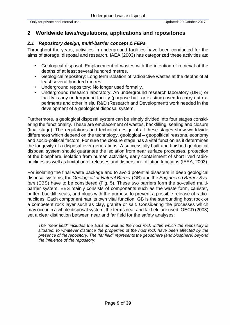
Deep geological repository programs have been conducted in many countries worldwide like Brazil, Bulgaria, Canada, China, Czech Republic, Finland, France, Hungary, India, Japan, Lithuania, Latvia, Mexico, Russia, Slovak Republic, Slovenia, South Africa, Spain, Sweden, Switzerland, Ukraine, United Kingdom and USA. Special attention should be given to the Great East Japan Earthquake happened in 2011. This earthquake has trig-gered a tsunami which results in damage and reactor meltdown so that a worldwide dis-cussion about the atomic energy and the safe storage of nuclear waste has begun. The following paragraphs concerning disposal structures in Germany (Fig. 9) were compiled by using up-to-date information from the state authorities of BfS, BfE and BGE (German Federal Company for the Permanent Storage of Radioactive Waste). Concerning the final disposal of nuclear wastes in Germany, research, planning and con-struction have been conducted for underground repositories or research facilities Asse II, Konrad, Gorleben and Morsleben by the Federal Company for Radioactive Waste Dis-posal, DBE (status as of April 2017). The Konrad disposal facility is a decommissioned iron ore mine in Salzgitter city (Lower Saxony County). The conversion of the Konrad Mine into a repository for negligible heat-generating waste (Low and Intermediate-Level radioactive waste) is currently being realised. It is allowed to be disposed off maximum 303,000 m³ of radioactive waste in an iron ore layer with 12 m to 18 m thickness. Morsleben belongs to Ingersleben municipality in Saxony-Anhalt County. The geological structure of Morsleben repository consists of simply cap rock, anhydrite, potash salt and rock salt. From 1971 to 1998 the salt mine Morsleben (disposal facility - ERAM) was used as a final disposal for Intermediate-level (ILW) and Low-level radioactive wastes (LLW). 36,754 m³ of waste have been disposed. The final closure will be finalized within the next few years.

Underground waste disposal
Only for private and internal use! Updated: 20 October 2017
Page 19 of 39
The Gorleben exploratory mine is in the far north-east of the Lower Saxony County near to the Brandenburg and Saxony-Anhalt border. Two shafts with depths of 933 m and 840 m form the mine. The mine is approximately 4 km wide and 14 km long and it is in the centre of the Gorleben salt dome. The investigations of Gorleben salt dome as a potential final disposal of High-Level radioactive Waste (HLW) has been conducted since 1979. The political discussions on the destiny of Gorleben mine as a repository are still going on. The storage of castor containers with radioactive wastes in Gorleben Mine was allowed until 2034 (status as of March 2016). Final results about the suitability of Gorleben are not available yet since this should be assessed by means of exploration measures. The Asse II nuclear facility is an abandoned salt mine near the town Remlingen in Lower Saxony County. It was used as a repository to test handling and storage of radioactive waste. The geological structure there simply consists of cap rock, rock salt, anhydrite, potash salt. In 13 former salt mining chambers, approximately 47,000 m³ with ILW and LLWs are stored. Several problems appeared in Asse II such as saline solution infiltration and stability of openings. BfS (2017) reported 12.5 m3/day of groundwater infiltration into Asse. Subsequent to waste retrieval, it is planned to conduct a decommissioning. The German authorities set the deadline as the year 2031 for finalizing the search for a final repository. In the framework of researches, several locations with different host rock options have been investigated. Attention should be paid to the fact that salt is currently still considered as the most fa-vourable host rock for a repository in Germany. In-situ and laboratory tests have been performed to improve state-of-art expertise in salt mechanics over decades (e.g. SALT-MECH-conferences). Compared to salt the knowledge about alternative host rock for-mations, especially crystalline rocks, is much lower and consequently, a fair and compre-hensive comparison is not possible at the moment.
Underground waste disposal
Only for private and internal use! Updated: 20 October 2017
Page 20 of 39
Figure 9: Illustration of underground situations for radioactive waste disposal / research sites in Germany:
Asse II (BfS, 2014), Gorleben (BfS, 2017), Konrad (BfS, 2016) and Morsleben (BfS, 2015b).

Underground waste disposal
Only for private and internal use! Updated: 20 October 2017
Page 21 of 39
3 Geotechnical aspects
3.1 Geotechnical terms and definitions concerning underground waste disposals
This chapter focus on the hydraulic-geomechanical behaviour of the three main host rock types (clay, granite and salt) regarding underground operations for waste disposal. Well-designed scientific and technical investigations should be performed before the planning and construction of underground waste disposals is started. Faybishenko et al. 2016 sum-marized key scientific challenges which may be encountered concerning radioactive waste disposal operations:
Prediction of the evolution of a repository site,
Characterization of deep geological environments,
Behaviours of deep rock mass, groundwater, and engineering material under cou-pled conditions,
Behaviour of engineering material under coupled conditions,
Geochemical behaviour of transuranic radionuclides with low concentration and its migration (nonrelevant for this work),
Safety assessment of disposal system. THMC coupled behaviour of rock mass has to be considered. Coupling means the inter-changing of thermal, hydraulic and mechanical (also chemical) components of a porous media as well as fractured ones via internal or external impacts. The excavation induced coupled behaviour of a rock wherein an excavation proceeded can be considered as an external or artificial impact. Some coupling incidents may be thus observed during and also after the excavation of drifts in host rocks (Fig. 10). THMC behaviour of a rock may drastically change due to an excavation. These changes can be monitored by geotech-nical instruments (see Chapter 3.2). A simple example for HM coupling is the change in pore pressure and effective stress around the drift. During the underground excavation in host rocks, damaged zones are created mainly due to stress redistributions, damage by blasting or cutting, relative humidity change during ventilation and induced temperature by tunnel excavators. Among other explanations such as creep of salt and shrink-age/swelling of clay, THMC coupling may influence so-called EDZ/EdZ. These abbrevia-tions stand for the Excavation Damaged Zone (EDZ) and the Excavation disturbed Zone (EdZ). TSANG et al. (2005) defined these two terms:
The Excavation disturbed Zone (EdZ) is a zone with hydromechanical and geochemical modifications without major changes in flow and transport properties. Furthermore, the Ex-cavation Damaged Zone (EDZ) is then a zone with hydromechanical and geochemical mod-ifications inducing significant changes in flow and transport properties e.g. several orders of magnitude increase in effective flow permeability.
The geometry of EDZ/EdZ depends on several factors (Blümling et al. 2007 and Bossart et al. 2002):
- Material anisotropy (e.g. Young’s modulus and permeability) - Stress anisotropy (magnitude and orientation) - Pre-existence of local inhomogeneities and natural fracture zones - Tunnel geometry and support system - Excavation method (Pneumatic hammering, blasting, roadheader, tunnel boring machine
etc.).

Underground waste disposal
Only for private and internal use! Updated: 20 October 2017
Page 22 of 39
.
Figure 10: Conceptual sketch of EDZ/EdZ around a tunnel together with tunnel face pictures after excava-
tion from URLs Mont Terri in Switzerland (Yong et al. 2008) and Bure in France (Faybishenko et al. 2016).
As mentioned above, creep behaviour of salt and shrinkage/swelling behaviour of clay may influence EDZ/EdZ so the repository safety measures, as well. Creep behaviour re-sults in self-healing/sealing of a salt and this attribute is considered to be favourable for a host rock (see Chapter 2.2). According to Heusermann et al. (1982), creep behaviour of a rock salt over time can be divided into three phases; (I) transient phase, (II) stationary phase and (III) tertiary phase under constant loading (see Fig. 11). Another challenging incident encountered during repository operations is swelling/shrinkage of clay. Haines (1923) and Stirk (1954) defined the shrinkage in soils as the specific volume change in relation to its water content, and they added that this occurs due to clay swelling proper-ties. The specific clay minerals in soils and rocks such as montmorillonite cause this vol-ume changes through chemical processes. Zhang et al. (2010) measured strains in axial direction under varying relative humidity (RH) conditions in a Callovo-Oxfordian argillite rock specimen. The specimen was exposed to wetting and drying. As relative humidity (RH, [RH] = %) have been naturally changed then strains (axial, radial and volumetric, %) exhibited different values with different rates. This happens via water content change since with increasing water content, rock volume has been increasing due to pore water uptake (swelling) and decreasing water content caused pore water release (shrinkage). Burgers Model, the Norton Power Law (1929) or the WIPP Model are some of the most common models among several others, and even more sophisticated mathematical mod-els (Hampel et al. 2016) which have been developed in order to formulate the creep be-havior of salts under applied stresses. The Burgers model is a physical analogue to creep behavior of salts and consist of a connection in series by Kelvin and Maxwell elements as depicted in Fig. 12. These elements are combinations of springs and dashpots.

Underground waste disposal
Only for private and internal use! Updated: 20 October 2017
Page 23 of 39
Figure 11: Creep behaviour of a rock salt (Heusermann et al. 1982) and swelling behaviour of a clay rock
over time (Zhang et al. 2010).
Figure 12: Pictogram of the Burgers Model including Maxwell and Kelvin elements.
3.2 Geotechnical computations, experiments and measurements concerning un-derground waste disposals
Many URLs have been operating in several countries with the intention of conducting R&D activities for investigating scientific challenges mentioned in the previous chapters. The main focus is on the research about future disposal of HLWs and their impacts on biosphere. Former and recent worldwide URLs are given in Tab. 3 (OECD 2013).

Underground waste disposal
Only for private and internal use! Updated: 20 October 2017
Page 24 of 39
Table 3: World-wide former and current URLs (OECD 2013).
Name of the URL / Location Host rock Depth
Asse Mine in Germany
Permian rock salt anticline
- Mining levels between 490 m and 800 m.
- Mined cavern at 950 m.
- Waste emplacement at 511 m
and 750 m levels.
Tono Mine in Japan Neogene sedimentary rock 130 m.
Kamaishi Mine in Japan Granite 300-700 m
Stripa Mine in Sweden Granite 360-410 m. Grimsel Test Site (GTS) in Swit-
zerland Granite 450 m
Mont Terri in France Opalinus clay (hard clay 250-320 m. Olkiluoto Research Tunnel in
Finland Granite (tonalite) 60-100 m.
Climax in USA Granite 420 m.
G-Tunnel in USA Tuff > 300 m.
Amelie in France Bedded salt No information
Fanay-Augères in France Granite No information
Tournemire Facility in France Sediments (hard clay) 250 m. High-Activity Disposal Experi-ment Site Underground Re-
search Facility (HADES-URF) in Belgium
Boom clay (plastic clay) 230 m.
AECL Underground Research Laboratory in Canada
Granite 240-420 m.
Mizunami Underground Re-search Laboratory (MIU) in Ja-
pan Granite
Research galleries at 300 m (in operation), 500 m (under con-
struction) and 1,000 m (planned).
Horonobe Underground Re-search Laboratory in Japan
Neogene sedimentary rock
Research galleries at 140 m and 250 m (in operation), 350 m (to
be constructed) and 500 m (planned).
Äspö Hard Rock Laboratory in Sweden
Granite Several depths between 200 m
and 450 m.
Busted Butte in the USA Bedded tuff, Calico Hills For-
mation 100 m.
Korea Underground Research Tunnel (KURT) in South Korea
Granite 90 m.
ONKALO in Finland Granite (tonalite) 500 m.
Gorleben in Germany Salt dome About 900 m below ground
Konrad in Germany Limestone covered with shale 800-1,300 m below ground
Morsleben in Germany Salt dome Several depths up to 525 m be-
low ground.
Pécs (Mecsek Mountain) in Hun-gary
Indurated clay, Boda Claystone
formation 1,000 m.
Waste Isolation Pilot Plant (WIPP) in the USA
Salt (bedded), Salado
Formation 655 m.
Exploratory Studies Facility (ESF) in the USA
Welded tuff, Calico Hills
Formation 300 m.
Bure in France Shale (indurated clays), Cal-
lovo-Oxfordian Argillite 450-500 m.

Underground waste disposal
Only for private and internal use! Updated: 20 October 2017
Page 25 of 39
As given in Tab. 3, the depth of URLs ranges between 60 m and 1,300 m and clay, gran-ite, salt and tuff are common host rocks. Some countries, which are not listed above, like China are planning to build their own URLs. In these URLs, many large-scale and some-times multinational R&D projects are conducted with the following aims (Kickmaier 1997, Wang 2007, OECD 2013):
a. Developing methods, equipment and experience in repository construction, operation and closure, and in waste retrieval:
- Quantification of impacts of excavation on local system, - Further development and testing of excavation techniques, - Simulation of effects caused by emplacement of radioactive waste (heat, radiation,
nuclide release, mechanical impact, gas release): FEBEX project at Grimsel and the international DECOVALEX project,
- Studies of material interactions in repository environment such as experiments re-lated to long-term processes, post-operational phases, corrosion, geo-mechanical stability and etc.
- Demonstration of Engineered Barrier Systems (feasibility), - Demonstration of emplacement techniques and waste retrieval, - Demonstration of durable and non-intrusive (from outside and not influencing)
monitoring techniques, b. Studies of EDZ / EdZ - ZEDEX experiment at Äspö URL, c. Site characterization studies, d. Hydrogeological tests, e. In-situ radionuclides migration tests, f. Prototype repository study: EU’s ESDRED Project, g. Natural analogue and anthropogenic analogue studies, h. Development of conceptual and numerical models of processes potentially relevant to
radionuclide transport through rock.
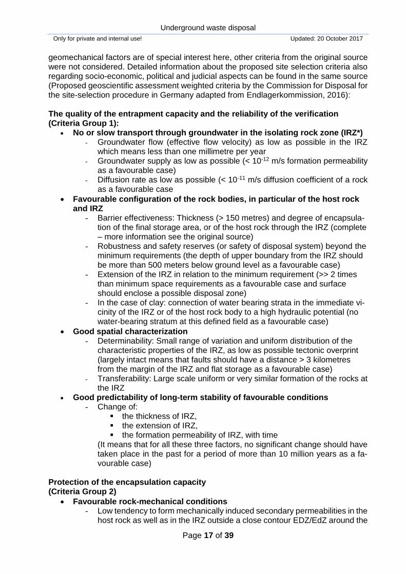
In addition to the geophysical and geotechnical researches conducted in various URLs, numerous laboratory experiments on suitable host rock specimens have been performed. Some of these are for instance swelling pressure tests on clay specimen or triaxial steady-state creep tests on salt specimen, permeability tests under different THMC conditions etc. Not only host rocks as a geological barrier have been tested by using geotechnical methods but also the components of EBS (e.g. bentonite as a backfill material). Monitor-ing systems are used to measure temperature, deformation and pressure changes in and around the host rock. Deformation changes can be measured by extensometers or de-flectometers and pore water pressure by multi packer systems. Environmental monitoring of repositories is also vital as well as the monitoring of repository systems before and after closure. Radioactivity measurements of water, ground, vegetation and air in the di-rect vicinity of a repository should be thus performed. All these test results from laboratory or in-situ experiments and researches are being used to model repositories or their struc-tural components. Modelling practise has been continuously developing considering is-sues such as tunnel excavation, heating experiments, shaft sinking, EBS safety assess-ments and radionuclide transport scenarios etc. Based on the used discretization method of a model, Finite Element (FEM), Finite Differ-ence (FDM) and Discrete Element (DEM) numerical codes have been using for under-ground waste disposal operations. One of these modelling studies was performed by Yildizdag et al. (2008) in the framework of a project considering EBS safety assessment (see Fig. 13). In-situ experiments of the two heaters surrounded by bentonite and sand buffers in the granite were simulated by using the TH2 (two phase) coupled code. Two
Underground waste disposal
Only for private and internal use! Updated: 20 October 2017
Page 26 of 39
heaters are shown with pink coloured and silver coloured rectangles on the left and right hand side of the figure, respectively. As it was depicted at that figure, only the half of the experiment domain was modelled two-dimensional by using axial symmetry. Simulated capillary pressure during the temperature change was calculated within the time interval of approximately 1 year (362 days). This experiment simply represents the Multi-Barrier design with the host rock granite. Considering worldwide numerical modelling projects for disposal systems, special atten-tion should be given to the international project DECOVALEX (DEvelopment of COupled models and their VALidation against EXperiments) which has been conducted since 1992. It is initiated to develop, perform, calibrate and compare numerical codes for the performance assessment of repositories in geological formations. Through this project, the international experts try to improve the understanding of THMC coupling processes in the near field of waste by using numerical codes. Jing, Hudson and Birkholzer de-scripted the scientific and technical objectives of this project as below (Sugita et al. 2016):
- to increase the basic understanding of THMC coupled processes in fractured rocks (crys-talline, sedimentary, argillaceous) and buffer materials;
- to investigate the predictive capabilities of different codes to field experiments and to per-form verification of codes;
- to exchange experimental data, and improve the understanding of the constitutive behav-iour of crystalline and argillaceous rock masses and buffer materials;
- to perform THMC calculations in a performance/safety assessment context; and - to review the state-of-the art in coupled THMC issues in performance assessment.
Numerical modelling of the EBS experiment in Horonobe URL in Japan and their results are depicted in Fig. 14 (Sugita et al. 2016). This experiment was performed in the frame-
Figure 13: In-situ heater experiment (left side, Goudarzi et al. 2007) and its simulation showing computed
capillary pressure change at selected points in time (right side, Jobmann & Yildizdag et al. 2008).

Underground waste disposal
Only for private and internal use! Updated: 20 October 2017
Page 27 of 39
Fig. 14: Numerical modelling of the in-situ full-scale EBS experiment at the Horonobe URL (Japan) as a
task of the DECOVALEX-2015 Project (adapted from Sugita et al. 2016).
work of the DECOVALEX Project. Different numerical codes were employed by project partners; BGR (Federal Institute for Geosciences and Natural Resources, Germany), CAS (Institute of Rock and Soil Mechanics, Chinese Academy of Sciences, China), LBNL/DOE (Lawrence Berkeley National Laboratory, USA), Inha Univ./KAERI (Inha Uni-versity/Korean Atomic Energy Research Institute, Republic of Korea) and JAEA (Japan Atomic Energy Agency, Japan). In addition to the modelling studies mentioned before, specific researches on sealing sys-tems have been also conducted. Impact of EDZ/EdZ and THMC coupling among others on these elements have been evaluated through model-assessed experiments and pre-liminary assessments. Numerical models have been using to estimate thermal, hydraulic, mechanical and chemical behaviours of sealing system elements under realistic condi-tions or in case of fictive scenarios. Simulation results obtained were used to check the integrity of a repository and to avoid possible disasters. These disasters can have geo-genic origins (earthquake, ice-age, tsunami etc.) or can occur due to anthropogenic inter-ventions (excavation, explosions etc.). Specific investigations were performed by Neubert (2014) about impacts of seismic loading on shaft sealing systems. This work was based on the security analyses in Gorleben Salt Mine which contains geological and seismolog-ical datasets. Possible impacts of an earthquake at the shaft sealing system was simu-

Underground waste disposal
Only for private and internal use! Updated: 20 October 2017
Page 28 of 39
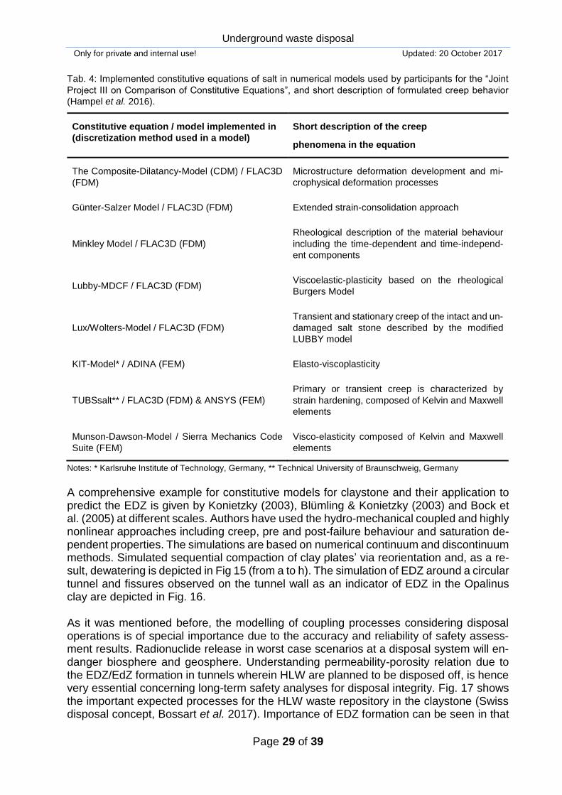
lated by using the commercial code FLAC3D. The author concluded that ‘[…] the numeri-cal investigations confirm the assumptions so far that an earthquake has only a minor impact under the conditions prevailing at the model site, which do not violate the integrity of the sealing structure.’ Another national research with the name “Joint Project III on Comparison of Constitutive Equations” was conducted in order to compare recent constitutive equations for salt rocks within the time period from 2010 to 2016 (Hampel et al. 2016). This research was based on thermo-mechanical simulations including self-healing of salt. Documentation, verifica-tion and comparison of current methods for the safe disposal of HLWs in salt formations were the ultimate goal of this project. The data from underground structures and labora-tory experiments were collected from the Asse Mine (Germany) and the WIPP site (USA). Eight selected constitutive equations for salt, which are implemented into numerical mod-els, were then employed to compare measurements with simulation results. Moreover, benchmarking studies were performed between these constitutive equations. Table 4 summarizes the implemented constitutive equations in the numerical models which are used in the project for the benchmarking. Furthermore, general classification of these equations is given as: microphysics based (CDM), macroscopic-phenomenological struc-ture-adapting (Günter-Salzer) and rheological viscoelastic-plasticity (the rest). Except the creep phenomenon, others such as damage, dilatancy and self-healing were mathemat-ically described by the above-mentioned constitutive equations as well.
Underground waste disposal
Only for private and internal use! Updated: 20 October 2017
Page 29 of 39
Tab. 4: Implemented constitutive equations of salt in numerical models used by participants for the “Joint
Project III on Comparison of Constitutive Equations”, and short description of formulated creep behavior
(Hampel et al. 2016).
Constitutive equation / model implemented in
(discretization method used in a model)
Short description of the creep
phenomena in the equation
The Composite-Dilatancy-Model (CDM) / FLAC3D
(FDM)
Microstructure deformation development and mi-
crophysical deformation processes
Günter-Salzer Model / FLAC3D (FDM) Extended strain-consolidation approach
Minkley Model / FLAC3D (FDM)
Rheological description of the material behaviour
including the time-dependent and time-independ-
ent components
Lubby-MDCF / FLAC3D (FDM) Viscoelastic-plasticity based on the rheological
Burgers Model
Lux/Wolters-Model / FLAC3D (FDM)
Transient and stationary creep of the intact and un-
damaged salt stone described by the modified
LUBBY model
KIT-Model* / ADINA (FEM) Elasto-viscoplasticity
TUBSsalt** / FLAC3D (FDM) & ANSYS (FEM)
Primary or transient creep is characterized by
strain hardening, composed of Kelvin and Maxwell
elements
Munson-Dawson-Model / Sierra Mechanics Code
Suite (FEM)
Visco-elasticity composed of Kelvin and Maxwell
elements
Notes: * Karlsruhe Institute of Technology, Germany, ** Technical University of Braunschweig, Germany
A comprehensive example for constitutive models for claystone and their application to predict the EDZ is given by Konietzky (2003), Blümling & Konietzky (2003) and Bock et al. (2005) at different scales. Authors have used the hydro-mechanical coupled and highly nonlinear approaches including creep, pre and post-failure behaviour and saturation de-pendent properties. The simulations are based on numerical continuum and discontinuum methods. Simulated sequential compaction of clay plates’ via reorientation and, as a re-sult, dewatering is depicted in Fig 15 (from a to h). The simulation of EDZ around a circular tunnel and fissures observed on the tunnel wall as an indicator of EDZ in the Opalinus clay are depicted in Fig. 16. As it was mentioned before, the modelling of coupling processes considering disposal operations is of special importance due to the accuracy and reliability of safety assess-ment results. Radionuclide release in worst case scenarios at a disposal system will en-danger biosphere and geosphere. Understanding permeability-porosity relation due to the EDZ/EdZ formation in tunnels wherein HLW are planned to be disposed off, is hence very essential concerning long-term safety analyses for disposal integrity. Fig. 17 shows the important expected processes for the HLW waste repository in the claystone (Swiss disposal concept, Bossart et al. 2017). Importance of EDZ formation can be seen in that

Underground waste disposal
Only for private and internal use! Updated: 20 October 2017
Page 30 of 39
figure. In case of possible migration of radionuclides subsequent to an accident in a re-pository, EDZ/EdZ may behave as potential leakage pathways. Life span of this reposi-tory is estimated to be equal to one million years. To evaluate these given processes for the repository safety assessment in such a long time interval needs numerical models and monitoring systems. Moreover, in order to understand dominating mechanisms in a rock for disposal operations, new measurement and modelling techniques have been constantly developing.
Figure 15: Simulation of clay compaction process with explicit consideration of clay plates, free and
bounded water: a to h show increasing compaction with reorientation of clay plates and dewatering (Bock
et al. 2005).

Underground waste disposal
Only for private and internal use! Updated: 20 October 2017
Page 31 of 39
Figure. 16: Simulation and field observation of EDZ in Opalinus Clay (Blümling & Konietzky, 2003)
Fig. 17: Expected processes during a possible evolution of the HLW repository in the claystone (adapted
from Bossart et al. 2017).

Underground waste disposal
Only for private and internal use! Updated: 20 October 2017
Page 32 of 39
4 References
Bechthold, W., Smailos, E., Heusermann, S., Bollingerfehr, W., Bazargan Sabet, B., Rothfuchs, T., Hansen, F. D. (2004): Backfilling and sealing of underground repos-itories for radioactive waste in salt (BAMBUS-II Project). Commission of the Euro-pean Communities, EUR 20621, 272 pp.
Bergström, U., Pers K., Almén Y. (2011): International perspective on repositories for low
level waste, Swedish Nuclear Fuel and Waste Management Co (SKB International AB), Report, SKB R-11-16, Stockholm, Sweeden.
Blümling, P. & Konietzky, H. (2003): Development of an Excavation Disturbed Zone in
Claystone (Opalinus Clay), Proc. Int. Symp. Geotech Measurements and Model-ling, Balkema, 1-5
Blümling, P., Bernier, F., Lebon, P., Martin, C.D. (2007): The excavation damaged zone
in clay formations time-dependent behaviour and influence on performance as-sessment, Physics and Chemistry of the Earth, 32-2007, pp 588-599.
BMWI - The German Federal Ministry for Economic Affairs and Energy (2008): Final dis-
posal of High-Level radioactive waste in Germany, The Gorleben Repository Pro-ject, leaflet.
Bock, H., Blümling, P., Konietzky, H. (2005): Study of the micromechanical behaviour of
Opalinus Clay: An example of co-operation across the ground engineering disci-plines, Bulletin of Engineering Geology and the Environment, May 2006, Volume 65, Issue 2, pp 195-207.
Bollingerfehr, W., Buhmann, D., Filbert, W. (2013): Status of the safety concept and safety
demonstration for an HLW repository in salt. Summary report (No. TEC-15-2013-AB). DBE Technology GmbH, Peine, Germany.
Bork, M., Kindt, A., Nierste, G., Walterscheidt, K. -H. (2001): Zusammenstellung interna-
tionaler Kriterien zur Bewertung und Auswahl von Standorten für die Endlagerung von radioaktiven Abfällen in tiefen geologischen Formationen, Gesellschaft für An-lagen- und Reaktorsicherheit (GRS) mbH, GRS - A – 2834, Bericht, Braun-schweig/Darmstadt, Deutschland.
Bossart, P., Meier, P.M., Moeri, A., Trick, T., Mayor, J.C. (2002): Geological and hydraulic
characterisation of the excavation disturbed zone in the Opalinus Clay of the Mont Terri Rock Laboratory, Engineering Geology, 66-2002, pp 19-38.
Bossart, P., Bernier, F., Birkholzer, J., Bruggeman, C., Connolly, P., Dewonck, S., Fu-
kaya, M., Herfort, M., Jensen, M., Matray, J-M., Mayor, J. C., Moeri, A., Oyama, T., Schuster, K., Shigeta, N., Vietor, T., Wieczorek, K. (2017): Mont Terri rock la-boratory, 20 years of research: introduction, site characteristics and overview of experiments. Swiss Journal of Geosciences, 110(1), 3-22.
Underground waste disposal
Only for private and internal use! Updated: 20 October 2017
Page 33 of 39
Brasser, T. & Droste, J. (2008): Endlagerung Wärmeentwickelnder Radioaktiver Abfälle in Deutschland, Anhang Endlagerstandorte Nationale und ausgewählte internatio-nale Standorte bzw. Standortkandidaten, Gesellschaft für Anlagen- und Reaktor-sicherheit-GRS, Braunschweig/Darmstadt, Deutschland.
Brasser, T., Droste, J., Müller-Lyda, I., Neles, J., Sailer, M., Schmidt, G., & Steinhoff, M.
(2008): Endlagerung wärmeentwickelnder radioaktiver Abfälle in Deutschland. GRS report, GRS-247, Gesellschaft für Anlagen-und Reaktorsicherheit - GRS, Braunschweig/Darmstadt, Deutschland.
BGR - Bundesanstalt für Geowissenschaften und Rohstoffe (2007): Endlagerung radioaktiver Abfälle in Deutschland, Untersuchung und Bewertung von Regionen mit potenziell geeigneten Wirtsgesteinsformationen, Bericht, Hannover/Berlin, Deutschland. BfS - Bundesamt für Strahlenschutz (2014): Schachtanlage Asse II, Gesamtdarstellung
zur Rückholungsplanung, BfS-25/14, Informationsschrift, Salzgitter, Deutschland. BfS - Bundesamt für Strahlenschutz (2015a): Information über die Schachtanlage Asse
II, Asse Einblicke, Informationsschrift, Remmlingen, Deutschland. BfS - Bundesamt für Strahlenschutz (2015b): Endlager Morsleben - Hintergründe, Maß-
nahmen und Perspektiven der Stilllegung, Salzgitter, Deutschland. BfS - Bundesamt für Strahlenschutz (2016): Endlager Konrad, Informationsschrift, Salz-
gitter, Deutschland. BfS - Bundesamt für Strahlenschutz (2017): Schachtanlage Asse II. Stand der Arbeiten
zur Rückholung, Informationsschrift, Salzgitter, Deutschland. BMU - Bundesministerium für Umwelt, Naturschutz und Reaktorsicherheit (2010): Sicher-
heitsanforderungen an die Endlagerung wärmeentwickelnder radioaktiver Abfälle, Bonn, Deutschland
Chapman, N., & Hooper, A. (2012): The disposal of radioactive wastes underground. Pro-
ceedings of the Geologists' Association, 123(1), 46-63. Jové Colón, C. J. et al. (2011): Disposal Systems Evaluations and Tool Development–
Engineered Barrier System (EBS) Evaluation, prepared for the US Department of Energy Used Fuel Disposition Campaign. SAND2010-8200.
Faybishenko, B., Birkholzer, J., Sassani, D., & Swift, P. (2017): International Approaches
for Nuclear Waste Disposal in: Geological Formations: Geological Challenges in Radioactive Waste Isolation - Fifth Worldwide Review, Lawrence Berkeley Na-tional Laboratory (LBNL), Berkeley, CA United States.
Freiesleben, H. (2013): Final disposal of radioactive waste. In: EPJ Web of Conferences,
Vol. 54, p. 01006. EDP Sciences.

Underground waste disposal
Only for private and internal use! Updated: 20 October 2017
Page 34 of 39
Goudarzi, R., Akesson, M., Hökmark, H. (2007): Sensors data report (Period 26.03.03 - 01.07.07), Äspö HRL, TBT Sweden, Report No. 10, Clay Tec. AB, July, IPR-07-21. p. 12.
Grahm, P., Malm, R. and Eriksson, D. (2015): System design and full-scale testing of the
Dome Plug for KBS-3V deposition tunnels, SKB TR-14-23, Swedish Nuclear Fuel and Waste Management Co (SKB), Stockholm, Sweden.
Haines, W. B. (1923): The volume changes associated with variations of water content in
soil. Journal of Agricultural Science, 13, pp 296–311. Hampel, A., Herchen, K., Lux, K. H., Günther, R. M., Salzer, K., Winkley, W., Pudewills,
A., Yildirim, S., Rokahr, R., Missal, C., Gährken, A., Stahlmann, J. (2016) Vergleich aktueller Stoffgesetze und Vorgehensweisen anhand von Modellberechnungen zum thermo-mechanischen Verhalten und zur Verheilung von Steinsalz, Synthe-sebericht, Verbundsprojekt, 01.10.2010 – 30.09.2016, Berlin, Deutschland.
Heusermann, S., Lux, K. H., & Rokahr, R. B. (1982): Entwicklung mathematischer Mo-
delle zur Beschreibung des Stoffverhaltens von Salzgestein in Abhängigkeit von der Zeit und von der Temperatur auf der Grundlage von Laborversuchen. Ab-schlussbericht zum Forschungsvorhaben ET 2011 A.
Hoth, P., Wirth, H., Reinhold, K., Bräuer, V., Krull, P., & Feldrappe, H. (2007): Endlage-
rung radioaktiver Abfälle in tiefen geologischen Formationen Deutschlands–Unter-suchung und Bewertung von Tongesteinsformationen. BGR Bundesanstalt für Ge-owissenschaften und Rohstoffe, Hannover, Deutschland.
IAEA - International Atomic Energy Agency (1997): Experience in selection and charac-
terization of sites for geological disposal of radioactive waste, Report, Vienna, Aus-tria.
IAEA - International Atomic Energy Agency (2003): Scientific and Technical Basis for the
Geological Disposal of Radioactive Wastes, Technical Report Series, No. 413, Vi-enna, Austria.
IAEA - International Atomic Energy Agency (2009): Safety Standards, Classification of
Radioactive Waste, General Safety Guide, No. GSG-1, Vienna, Austria. Jobmann, M., Bebiolka, A., Burlaka, V., Herold, P., Jahn, S., Lommerzheim, A.,
Maßmann, J., Meleshyn, A., Mrugalla, S., Reinhold, K., Rübel, A., Stark, L., Ziefle, G. (2017): Safety assessment methodology for a German high-level waste repos-itory in clay formations, Journal of Rock Mechanics and Geotechnical Engineering, 9, pp 856-876.
Jobmann, M., Yildizdag, K., Herklotz, M., Polster, M., Schonebeck, M., & Uhlig, L. (2008):
Investigation on the THM behavior of a heated bentonite barrier by measurements and numerical calculations, MUSTER, Final report (No. TEC--25-2008-AB). DBE Technology GmbH, Peine, Germany.
Underground waste disposal
Only for private and internal use! Updated: 20 October 2017
Page 35 of 39
KIT - Karlsruher Institut für Technologie (2017): Verschlusssysteme – Konzepte, Bau-stoffe, Simulation, Demonstration und Anwendung, Fachgespräch, Freiberg 03.-04.05.2017, Materialienband, Eggenstein-Leopoldshafen, Deutschland.
Kickmaier, W. and McKingley, I. (1997): A review of research carried out in European
rock laboratories, Nuclear Engineering and Design, 176 (1-2), pp 75–81. Kommission Lagerung hoch radioaktiver Abfallstoffe - Endlagerkommission (2016) Ver-
antwortung für die Zukunft, Ein faires und transparentes Verfahren für die Auswahl eines nationalen Endlagerstandortes, Abschlussbericht, Berlin, Deutschland.
Konietzky, H. (2003): Tonsteine als Endlagerwirtsgestein, Veröffentlichung vom Institut
für Geotechnik, TU Bergakademie Freiberg, 2003-2, 211-221, Deutschland. Mariner, P. E., Lee, J. H., Hardin, E. L., Hansen, F. D., Freeze, G. A., Lord, A. S., Gold-
stein, B. & Price, R. H. (2011): Granite disposal of US high-level radioactive waste. Sandia National Laboratories Scientific Report SAND2011-6203. Albuquerque, New Mexico.
Müller-Hoeppe, N., Engelhardt, H. J., Lerch, C., Linkamp, M., Buhman, D., Caikowski, O.,
Wieczorek, K., Herbert, H. J. & Xie, M. (2012) Integrität geotechnischer Barrieren–Teil 1: Vorbemessung - Bericht zum Arbeitspaket 9.2 - Vorläufige Sicherheitsana-lyse für den Standort Gorleben, GRS-287, GRS, Köln, Deutschland.
Neubert, N. (2014) Standsicherheit und Integrität von geotechnischen Barrieren unter
Erdbebeneinwirkung, Diplomarbeit, Technische Universität Bergakademie Frei-berg, Deutschland.
OECD - Organisation for Economic Cooperation and Development (2003): Engineered
Barrier Systems and the Safety of Deep Geological Repositories, State-of-the-art Report, EUR 19964 EN.
OECD - Organisation for Economic Cooperation and Development (2013): Underground
Research Laboratories (URL), Radioactive Waste Management, NEA/RWM/R(2013)2.
Rindo H. (2014): Japan Nuclear Fuel Ltd. – JNFL: Conditioning of LLW, ILW and HLW,
Japan Atomic Energy Agency, International Atomic Energy Agency Scientific Fo-rum: Radioactive Waste – Meeting the Challenge, Science and Technology for Safe and Sustainable Solutions, 23-24 September 2014, Vienna, Austria, Presen-tation.
Rothfuchs, T. (2011) Verschlusssysteme in Endlagern für wärmeentwicklende Abfälle in
Salzformationen, Workshop der GRS in Zusammenarbeit mit dem Projektträger Karlsruhe PTKA-WTE, Braunschweig, 24. – 25. August 2010, GRS Köln, Deutsch-land.
Stirk, G. B. (1954): Some aspects of soil shrinkage and the effect of cracking upon air
entry into the soil. Australian Journal of Soil Research, 5, 279–290.

Underground waste disposal
Only for private and internal use! Updated: 20 October 2017
Page 36 of 39
Sugita, Y., Kwon, S., Lee, C., Maßmann, J., Pan, P., Rutqvist, J. (2016) DECOVALEX-2015 project, Task B2 Final report, TRITA-LWR.REPORT 2015:05
Tsang, C. F., Bernier, F. and Davies, C. (2005): Geohydromechanical processes in the
Excavation Damaged Zone in crystalline rock, rock salt, and indurated and plastic clays - in the context of radioactive waste disposal, International Journal of Rock Mechanics and Mining Sciences, 42(1), 109-125.
Tuli, J. K. (2005): Nuclear wallet cards, Brookhaven National Laboratory, New York, USA. Wang, J. (2007): Key scientific challenges in geological disposal of high level radioac-
tive waste. Engineering Sciences, (4), 45–50. Yildizdag, K., Shao, H., Hesser, J. (2012): Coupled HM modelling of Mine-by experiment
at Meuse-Haute-Marne (MHM) URL, France, Final Report, BGR Hannover Ger-many.
Yildizdag, K., Shao, H., Hesser, J., Noiret, A., & Sönnke, J. (2014): Coupled hydrome-
chanical modelling of the mine-by experiment at Meuse–Haute–Marne under-ground rock laboratory France. In: S. Norris, J. Bruno, M. Cathelineau, P. Delage, C, Fairhurst, E. C. Gaucher, et al. (Eds.), Clays in natural and engineered barriers for radioactive waste confinement (pp. 265–278). Geological Society London Spe-cial Publication.
Zhang, C. L., Czaikowski, O., & Rothfuchs, T. (2010): Thermo-hydro-mechanical behav-
iour of the Callovo-Oxfordian clay rock. Final Report of the BURE-HAUPT/EC-TIMODAZ Project, GRS-266. Gesellschaft für Anlagen und Reaktorsicherheit (GRS), Cologne, Germany.

Underground waste disposal
Only for private and internal use! Updated: 20 October 2017
Page 37 of 39
5 Appendix
Table 5: Repository related properties of potential host rocks (adapted from BGR, 2007): Thermal-Hydraulic-Mechanical-Chemical (THMC) characteristics of
them in the upper table and design related-technical factors in the lower table together with the qualitative scale.
COMPONENTS ROCK SALT ARGILLACEOUS ROCK / CLAY CRYSTALLINE ROCK / GRANITE
Heat conductivity High Low Intermediate
Permeability Practically impermeable Very low to low Very low (intact) to permeable (frac-
tured)
Stability Intermediate Low to intermediate High
Deformation behaviour Viscous (creep) Plastic to brittle Brittle
Stability of cavities Inherent stability Support required High (intact) to low (highly fractured)
In-situ stress state Lithostatic isotropic Anisotropic Anisotropic
Dissolution behaviour High Very low Very low
Sorption capacity Very low Very high Intermediate to high
Thermal endurance High Low High

Underground waste disposal
Only for private and internal use! Updated: 20 October 2017
Page 38 of 39
COMPONENTS ROCK SALT ARGILLACEOUS ROCK / CLAY CRYSTALLINE ROCK / GRANITE
Emplacement depth Approximately 900 m Approximately 500 m 500-1,200 m
Storage technique * Drifts and deep boreholes Drifts and/or short boreholes Boreholes or drifts
Storage temperature Max. 200°C Max. 100°C Max. 100°C (with bentonite backfill)
Backfill * Crushed salt Bentonite Bentonite
Interim storage period (fuel rods
and HLW canisters) Min. 15 years Min. 30-40 years Min. 30-40 years
Drift reinforcement Not necessary Necessary and potentially very
complex
Necessary in severely fractured
zones
Container concept Established New development required for
Germany
New development required for Ger-
many
Mining experience Very extensive (salt-mining) Hardly any Extensive (iron ore mining)
* Is adapted to the host rock in question.
Qualitative scale:

Underground waste disposal
Only for private and internal use! Updated: 20 October 2017
Page 39 of 39


![Scanned Document - avi.net.pl ELSR kable... · [18] IBExU Institut für Sicherheitstechnik GmbH An-Institut der TU Bergakademie Freiberg Special conditions The special conditions](https://static.fdocuments.us/doc/165x107/5f03599c7e708231d408c76a/scanned-document-avinetpl-elsr-kable-18-ibexu-institut-fr-sicherheitstechnik.jpg)
